EP2650476A2 - Virole d'extrémité de pales de turbomachine avec configuration de carter parallèle - Google Patents
Virole d'extrémité de pales de turbomachine avec configuration de carter parallèle Download PDFInfo
- Publication number
- EP2650476A2 EP2650476A2 EP13163003.0A EP13163003A EP2650476A2 EP 2650476 A2 EP2650476 A2 EP 2650476A2 EP 13163003 A EP13163003 A EP 13163003A EP 2650476 A2 EP2650476 A2 EP 2650476A2
- Authority
- EP
- European Patent Office
- Prior art keywords
- tip shroud
- structural component
- leading edge
- stationary structural
- corresponding portion
- Prior art date
- Legal status (The legal status is an assumption and is not a legal conclusion. Google has not performed a legal analysis and makes no representation as to the accuracy of the status listed.)
- Granted
Links
Images


Classifications
-
- F—MECHANICAL ENGINEERING; LIGHTING; HEATING; WEAPONS; BLASTING
- F01—MACHINES OR ENGINES IN GENERAL; ENGINE PLANTS IN GENERAL; STEAM ENGINES
- F01D—NON-POSITIVE DISPLACEMENT MACHINES OR ENGINES, e.g. STEAM TURBINES
- F01D5/00—Blades; Blade-carrying members; Heating, heat-insulating, cooling or antivibration means on the blades or the members
- F01D5/12—Blades
- F01D5/22—Blade-to-blade connections, e.g. for damping vibrations
- F01D5/225—Blade-to-blade connections, e.g. for damping vibrations by shrouding
-
- F—MECHANICAL ENGINEERING; LIGHTING; HEATING; WEAPONS; BLASTING
- F01—MACHINES OR ENGINES IN GENERAL; ENGINE PLANTS IN GENERAL; STEAM ENGINES
- F01D—NON-POSITIVE DISPLACEMENT MACHINES OR ENGINES, e.g. STEAM TURBINES
- F01D11/00—Preventing or minimising internal leakage of working-fluid, e.g. between stages
- F01D11/08—Preventing or minimising internal leakage of working-fluid, e.g. between stages for sealing space between rotor blade tips and stator
-
- F—MECHANICAL ENGINEERING; LIGHTING; HEATING; WEAPONS; BLASTING
- F05—INDEXING SCHEMES RELATING TO ENGINES OR PUMPS IN VARIOUS SUBCLASSES OF CLASSES F01-F04
- F05D—INDEXING SCHEME FOR ASPECTS RELATING TO NON-POSITIVE-DISPLACEMENT MACHINES OR ENGINES, GAS-TURBINES OR JET-PROPULSION PLANTS
- F05D2250/00—Geometry
- F05D2250/30—Arrangement of components
- F05D2250/31—Arrangement of components according to the direction of their main axis or their axis of rotation
- F05D2250/312—Arrangement of components according to the direction of their main axis or their axis of rotation the axes being parallel to each other
Definitions
- turbomachines and, more particularly, a turbomachine blade tip shroud and a casing in a generally parallel configuration.
- Turbomachines include compressors and turbines, such as gas turbines, steam turbines, and hydro turbines.
- turbomachines include a rotor, which may be a shaft or drum, to which turbomachine blades are attached.
- Certain turbomachine blades may include tip shrouds and/or seals to meet structural and/or performance requirements.
- the tip shrouds and/or seals may reduce flow leakage through the cavity or passage between the turbomachine blades and a stationary structural component, such as a static shroud, surrounding the turbomachine blades and the rotor.
- Existing tip shroud and seal design may not adequately limit or reduce flow leakage between the turbomachine blades and the stationary structural component surrounding the turbomachine blades and the rotor, which may result in a reduction in turbomachine efficiency.
- existing stationary structural component design may not adequately limit or reduce flow leakage between the turbomachine blades and the stationary structural component surrounding the turbomachine blades and the rotor.
- the invention resides in a turbomachine including a turbomachine blade and a stationary structural component.
- the turbomachine blade includes a tip shroud having a leading edge portion where the leading edge portion has a first surface.
- the stationary structural component is disposed about the turbomachine blade and includes a corresponding portion corresponding to the leading edge portion of the tip shroud, where the corresponding portion has a second surface, where the first surface and the second surface have generally parallel contours.
- the disclosed embodiments include a turbomachine blade tip shroud and a turbomachine stationary structural component, where a leading edge portion of the turbomachine blade tip shroud and a corresponding portion of the turbomachine stationary structural component have a generally parallel configuration.
- the generally parallel configuration between the leading edge portion of the turbomachine blade tip shroud and the corresponding portion of the turbomachine stationary structural component may provide a more tailored clearance between the turbomachine blade tip shroud and the turbomachine stationary structural component. This may reduce the leakage of flow escaping through the clearance or cavity between the turbomachine blade tip shroud and the turbomachine stationary structural component. Additionally, the more tailored clearance may also reduce the mixing and/or flow churning loss in the clearance or cavity.
- FIG. 1 illustrates a block diagram of an embodiment of a gas turbine system 10 having a turbine 18 with turbine blades 22 and a stationary structural component 23, where the stationary structural component 23 and tip shrouds of the turbine blades 22 have a parallel configuration relative to one another.
- the system 10 includes a compressor 12, combustors 14 having fuel nozzles 16, and the turbine 18.
- the fuel nozzles 16 route a liquid fuel and/or gas fuel, such as natural gas or syngas, into the combustors 14.
- the combustors 14 ignite and combust a fuel-air mixture, and then pass hot pressurized combustion gases 20 (e.g., exhaust) into the turbine 18.
- the compressor 12 includes compressor blades 28.
- the compressor blades 28 within the compressor 12 are coupled to the rotor 24, and rotate as the rotor 24 is driven into rotation by the turbine 18, as discussed above.
- the compressor blades 28 compress air from an air intake into pressurized air 30, which is routed to the combustors 14, the fuel nozzles 16, and other portions of the gas turbine system 10.
- the fuel nozzles 14 then mix the pressurized air and fuel to produce a suitable fuel-air mixture, which combusts in the combustors 14 to generate the combustion gases 20 to drive the turbine 18.
- the rotor 24 may be coupled to a load 31, which may be powered via rotation of the rotor 24.
- the load 31 may be any suitable device that may generate power via the rotational output of the gas turbine system 10, such as a power generation plant or an external mechanical load.
- the load 31 may include an electrical generator, a propeller of an airplane, and so forth.
- reference may be made to various directions, such as an axial direction or axis 32, a radial direction or axis 34, and a circumferential direction or axis 36 of the turbine 18.
- FIG. 2 is a partial side view of an embodiment of the turbine blade 22 and the stationary structural component 23. More specifically, the illustrated embodiment of the turbine blade 22 includes a tip shroud 50 disposed on an outer radial end 52 of the turbine blade 22, where a leading edge portion 54 (e.g., surface) of the tip shroud 50 and a corresponding portion 56 (e.g., surface) of the stationary structural component 23 have a generally parallel configuration.
- the corresponding portion 56 of the stationary structural component 23 is generally contoured to be parallel with the leading edge portion 54 of the tip shroud 50.
- the slopes of the leading edge portion 54 of the tip shroud 50 may be generally similar to the slopes of the corresponding portion 56 of the stationary structural component 23.
- the tip shroud 50 is disposed at the outer radial end 52 of the turbine blade 22.
- the tip shroud 50 may serve to block flow leakage between the outer radial end 52 of the turbine blade 22 and the stationary structural component 23.
- the tip shroud 50 may help block a fluid flow 58 (e.g., a flow of the combustion gases 20 from the combustor 14 of FIG. 1 ) within the turbine 18 from passing from a leading edge 60 to a trailing edge 62 of the turbine blade 22 through a clearance (e.g., a cavity) 64 between the outer radial end 52 of the turbine blade 22 and the stationary structural component 23.
- a fluid flow 58 e.g., a flow of the combustion gases 20 from the combustor 14 of FIG. 1
- the tip shroud 50 may also include a labyrinth seal 66, which further blocks the fluid flow 58 from passing from the leading edge 60 to the trailing edge 62 through the clearance 64.
- the labyrinth seal 66 includes a single rail 68, which extends in the radial direction 34 towards a honeycomb insert 70 (e.g., a casing abradable surface) disposed on the stationary structural component 23.
- the labyrinth seal 66 may include multiple rails 68 and honeycomb inserts 70 (e.g., casing abradable surfaces).
- the tip shroud 50 includes a nose portion 72.
- the nose portion 72 of the tip shroud 50 and the remaining portion of the tip shroud 50 are not collinear.
- the nose portion 72 of the tip shroud 50 and the remaining portion of the tip shroud 50 form an angle 74, which may be less than 180 degrees.
- the angle 74 between the nose portion 72 of the tip shroud 50 and the remaining portion of the tip shroud 50 may be approximately 1 to 180, 2 to 160, 3 to 140, 4 to 120, 5 to 100, 6 to 80, 7 to 60, or 8 to 40 degrees.
- the nose portion 72 of the tip shroud 50 is generally parallel with the rotational axis 25 of the turbine 18, and the remaining portion of the tip shroud 50 is generally oriented at an angle 76 to the rotational axis 25 of the turbine 18.
- the angle 76 between the remaining portion of the tip shroud 50 and the rotational axis 25 of the turbine 18 may be approximately 0 to 75, 5 to 60, 10 to 45, or 15 to 30 degrees.
- the nose portion 72 of the tip shroud 50 and the remaining portion of the tip shroud 50 may be collinear.
- the nose portion 72 of the tip shroud 50 and the remaining portion of the tip shroud 50 may be collinear and may form a substantially constant angle with the rotational axis 25 of the turbine 18 (see, e.g., FIG. 6 ). Additionally, the nose portion 72 of the tip shroud and the remaining portion of the tip shroud 50 may be collinear and may be generally parallel with the rotational axis 25 of the turbine 18.
- the nose portion 72 of the tip shroud 50 includes a leading edge overhang 78. More specifically, the leading edge overhang 78 of the nose portion 72 of the tip shroud 50 extends over a leading edge 80 of the turbine blade 22 in an upstream axial direction 82. In this manner, the tip shroud 50 may further block the fluid flow 58 from passing from the leading edge 60 to the trailing edge 62 of the turbine blade 22 through the clearance 64 between the outer radial end 52 of the turbine blade 22 and the stationary structural component 23. For example, the leading edge overhang 78 may direct the fluid flow 58 down the turbine blade 22 generally in the radial direction 34, as indicated by arrow 84, or across the turbine blade 22 in the axial direction 32, as indicated by arrow 86.
- FIG. 3 is a partial side view of the embodiment of the turbine blade 22 and the stationary structural component 23 shown in FIG. 2 , illustrating the tip shroud 50 disposed on the outer radial end 52 of the turbine blade 22, where the leading edge portion 54 of the tip shroud 50 and the corresponding portion 56 of the stationary structural component 23 have a generally parallel configuration.
- the corresponding portion 56 of the stationary structural component 23 is generally contoured to be parallel with the leading edge portion 54 of the tip shroud 50.
- the clearance 64 between the tip shroud 50 and the stationary structural component 23 may be more tailored.
- the fluid flow 58 within the turbine 18 may be further reduced from passing from the leading edge 60 to the trailing edge 62 of the turbine blade 22 through the clearance 64 between the outer radial end 52 of the turbine blade 22 and the stationary structural component 23.
- the nose portion 72 of the tip shroud 50 corresponds with a second corresponding portion 106 of the stationary structural component 23.
- the nose portion 72 of the tip shroud 50 is generally parallel with the rotational axis 25 of the turbine 18.
- the second corresponding portion 106 of the stationary structural component 23 is generally parallel with the rotational axis 25 of the turbine 18.
- the second corresponding portion 106 of the stationary structural component 23 is disposed generally upstream from the nose portion 72 of the tip shroud 50.
- the nose portion 72 of the tip shroud 50 and the second corresponding portion 106 of the stationary structural component 23 are disposed generally opposite one another across the clearance 64 between the tip shroud 50 and the stationary structural component 23, thereby creating a generally parallel configuration between the nose portion 72 of the tip shroud 50 and the second corresponding portion 106 of the stationary structural component 23.
- the remaining portion of the tip shroud 50 (i.e., the portion of the tip shroud 50 not including the nose portion 72) is generally disposed at the angle 76 relative to the rotational axis 25 of the turbine blade 18.
- an intermediate portion 108 i.e., the portion of the tip shroud 50 between the nose portion 72 of the tip shroud 50 and the rail 68 of the labyrinth seal 66
- the intermediate portion 108 of the tip shroud 50 corresponds to a third corresponding portion 110 of the stationary structural component 23, which also is generally oriented at the angle 76 relative to the rotational axis 25 of the turbine 18.
- the third corresponding portion 110 of the stationary structural component 23 is disposed generally upstream from the intermediate portion 108 of the tip shroud 50.
- the intermediate portion 108 of the tip shroud 50 and the third corresponding portion 110 of the stationary structural component 23 are disposed generally opposite one another across the clearance 64 between the tip shroud 50 and the stationary structural component 23.
- the intermediate portion 108 of the tip shroud 50 and the third corresponding portion 110 of the stationary structural component 23 are generally arranged in a parallel configuration. In other words, the contours of the intermediate portion 108 of the tip shroud 50 and the third corresponding portion 110 of the stationary structural component 23 are generally parallel with one another.
- the tip shroud 50 includes the rail 68 of the labyrinth seal 66, which generally extends in the radial direction 34.
- the rail 66 has an upstream surface 112, which is generally vertical.
- the upstream surface 112 of the rail 66 extends generally in the radial direction 34.
- the upstream surface 112 of the rail 66 corresponds to a fourth corresponding portion 114 of the stationary structural component 23.
- the fourth corresponding portion 114 also extends generally in the radial direction 34 (i.e., the fourth corresponding portion 114 is generally vertical).
- leading edge 100 of the leading edge overhang 78, the nose portion 72 of the tip shroud 50, the intermediate portion 108 of the tip shroud 50, and the upstream surface 112 of the rail 68 are arranged adjacent to one another and in consecutive order along the tip shroud 50 in the axial direction 32, with the leading edge 100 of the leading edge overhang 78 being the most upstream.
- portions of the stationary structural component 23 corresponding to each of the above-mentioned portions of the tip shroud 50 are arranged adjacent to one another and in consecutive order.
- the first corresponding portion 102 of the stationary structural component 23, the second corresponding portion 106 of the stationary structural component 23, the third corresponding portion 110 of the stationary structural component 23, and the fourth corresponding portion 114 of the stationary structural component 23 are arranged in consecutive order along the stationary structural component 23 in the axial direction 32 and the radial direction 34, with the first corresponding portion 102 of the stationary structural component 23 being the most upstream.
- each portion of the leading edge portion 54 of the tip shroud 50 e.g., the leading edge 100, nose portion 72, etc.
- the portion of the stationary structural component 23 with which it corresponds e.g., the first corresponding portion 102, the second corresponding portion 106, etc.
- each portion of the leading edge portion 54 of the tip shroud 50 and the portion of the stationary structural component 23 with which it corresponds may be offset in the axial direction 32 the same or similar distance as every other portion of the leading edge portion 54 and the portion of the stationary structural component 23 with which they correspond.
- leading edge portion 54 of the tip shroud 50 and the corresponding portion 56 of the stationary structural component 23 are arranged in a generally parallel configuration.
- the generally parallel configuration of the leading edge portion 54 of the tip shroud 50 and the corresponding portion 56 of the stationary structural component 23 may help reduce leakage of the fluid flow 58 through the clearance 64 between the tip shroud 50 and the stationary structural component 23. Additionally, the generally parallel configuration may help reduce the generation of vortex flows within the clearance 64.
- the generally parallel configuration between the leading edge portion 54 of the tip shroud 50 and the corresponding portion 56 of the stationary structural component 23 may provide a more tailored and/or reduced clearance 64 between the tip shroud 50 and the stationary structural component 23, resulting in increased blockage of the fluid flow 58 through the clearance 64.
- FIG. 4 is a partial side view of an embodiment of the turbine blade 22 and the stationary structural component 23, illustrating the tip shroud 50 disposed on the outer radial end 52 of the turbine blade 22, where the tip shroud 50 includes the labyrinth seal 66 having two rails 68 (e.g., a first rail 150 and a second rail 152) and two honeycomb inserts 70 (e.g., casing abradable surfaces). Additionally, the leading edge portion 54 of the tip shroud 50 and the corresponding portion 56 of the stationary structural component 23 have a generally parallel configuration.
- the corresponding portion 56 of the stationary structural component 23 having a generally parallel configuration with the leading edge portion 54 of the tip shroud 50 may be contrasted with a corresponding portion 148 of the stationary structural component 23, which may not be generally parallel to the leading edge portion 54 of the tip shroud 50
- the intermediate portion 108 of the tip shroud 50 extends between the first rail 150 and the second rail 152.
- the leading edge portion 54 of the tip shroud 50 generally refers to the portion of the tip shroud 50 upstream of the first rail 150 of the labyrinth seal 66.
- the leading edge 100 of the leading edge overhang 78 corresponds with a first corresponding portion 154 of the stationary structural component 23.
- the leading edge 100 of the leading edge overhang 78 and the first corresponding portion 154 each extend generally in the radial direction 34.
- the first corresponding portion 154 of the stationary structural component 23 is disposed generally upstream from the leading edge 100 of the leading edge overhang 78, thereby creating the opening 104 of the clearance 64 between the tip shroud 50 and the stationary structural component 23.
- the nose portion 72 of the tip shroud 50 corresponds with a second corresponding portion 156 of the stationary structural component 23.
- the nose portion 72 of the tip shroud 50 is generally parallel with the rotational axis 25 of the turbine 18.
- the second corresponding portion 156 of the stationary structural component 23 is generally parallel with the rotational axis 25 of the turbine 18.
- the second corresponding portion 156 of the stationary structural component 23 is disposed generally upstream from the nose portion 72 of the tip shroud 50.
- the nose portion 72 of the tip shroud 50 and the second corresponding portion 156 of the stationary structural component 23 are disposed generally opposite one another across the clearance 64 between the tip shroud 50 and the stationary structural component 23, thereby creating a generally parallel configuration between the nose portion 72 of the tip shroud 50 and the second corresponding portion 156 of the stationary structural component 23.
- the tip shroud 50 includes the first rail 150 of the labyrinth seal 66, which generally extends in the radial direction 34.
- the first rail 150 has an upstream surface 158, which is generally vertical.
- the upstream surface 158 of the first rail 150 extends generally in the radial direction 34.
- the upstream surface 158 of the first rail 150 corresponds to a third corresponding portion 160 of the stationary structural component 23.
- the third corresponding portion 160 also extends generally in the radial direction 34 (i.e., the third corresponding portion 160 is generally vertical).
- the third corresponding portion 160 of the stationary structural component 23 is disposed generally upstream from the upstream surface 158 of the first rail 150 of the labyrinth seal 66. In this manner, the upstream surface 158 of the rail 150 and the third corresponding portion 160 of the stationary structural component are arranged in a generally parallel configuration relative to one another.
- a trailing edge portion 162 of the tip shroud 50 and the corresponding portion 56 of the stationary structural component 23 may have a parallel configured.
- the trailing edge portion 162 e.g., a portion of the tip shroud 50 aft or downstream of the second rail 152
- a corresponding portion 164 the stationary structural component 23 may have a parallel configuration.
- the trailing edge portion 162 of the tip shroud 50 and the corresponding portion 164 of the stationary structural component 23 have a conical configuration.
- the trailing edge portion 162 and the corresponding portion 164 have a slope approximately at the angle 76 relative to the rotational axis 25 of the turbine 18.
- the trailing edge portion 162 of the tip shroud 50 and the corresponding portion 164 of the stationary structural component 23 may have a cylindrical configuration, as indicated by reference numeral 166. That is, the trailing edge portion 162 of the tip shroud 50 and the corresponding portion 164 of the stationary structural component 23 may be generally parallel to the rotational axis 25 of the turbine 18.
- leading edge 100 of the leading edge overhang 78, the nose portion 72 of the tip shroud 50, and the upstream surface 158 of the first rail 150 are arranged adjacent to one another and in consecutive order along the tip shroud 50 in the axial direction 32, with the leading edge 100 of the leading edge overhang 78 being the most upstream.
- portions of the stationary structural component 23 corresponding to each of the above-mentioned portions of the tip shroud 50 are arranged adjacent to one another and in consecutive order.
- the first corresponding portion 154 of the stationary structural component 23, the second corresponding portion 156 of the stationary structural component 23, and the third corresponding portion 160 of the stationary structural component 23 are arranged in consecutive order along the stationary structural component 23 in the axial direction 32, with the first corresponding portion 154 of the stationary structural component 23 being the most upstream.
- each portion of the leading edge portion 54 of the tip shroud 50 e.g., the leading edge 100, nose portion 72, etc.
- the portion of the stationary structural component 23 with which it corresponds e.g., the first corresponding portion 154, the second corresponding portion 156, etc.
- each portion of the leading edge portion 54 of the tip shroud 50 and the portion of the stationary structural component 23 with which it corresponds may be offset in the axial direction 32 the same or similar distance as every other portion of the leading edge portion 54 and the portion of the stationary structural component 23 with which they correspond.
- leading edge portion 54 of the tip shroud 50 and the corresponding portion 56 of the stationary structural component 23 are arranged in a generally parallel configuration.
- the generally parallel configuration of the leading edge portion 54 of the tip shroud 50 and the corresponding portion 56 of the stationary structural component 23 may help reduce leakage of the fluid flow 58 through the clearance 64 between the tip shroud 50 and the stationary structural component 23.
- the generally parallel configuration between the leading edge portion 54 of the tip shroud 50 and the corresponding portion 56 of the stationary structural component 23 may provide a more tailored and/or reduced clearance 64 between the tip shroud 50 and the stationary structural component 23, resulting in reduction of leakage of the fluid flow 58 through the clearance 64.
- FIG. 5 is a partial side view of an embodiment of the turbine blade 22 and the stationary structural component 23, illustrating the tip shroud 50 disposed on the outer radial end 52 of the turbine blade 22, where the tip shroud 50 includes the labyrinth seal 66 having two rails 68 (e.g., the first rail 150 and the second rail 152) and two honeycomb inserts 70 (e.g., casing abradable surfaces), and the leading edge portion 54 of the tip shroud 50 and the corresponding portion 56 of the stationary structural component 23 have a generally parallel configuration.
- the tip shroud 50 includes the labyrinth seal 66 having two rails 68 (e.g., the first rail 150 and the second rail 152) and two honeycomb inserts 70 (e.g., casing abradable surfaces)
- the leading edge portion 54 of the tip shroud 50 and the corresponding portion 56 of the stationary structural component 23 have a generally parallel configuration.
- the nose portion 72 of the tip shroud 50 is not collinear with the remaining portion of the tip shroud 50 (i.e., the portion of the tip shroud 50 not including the nose portion 50), and the nose portion 72 is disposed at an angle 180 relative to the rotational axis 25 of the turbine 18.
- the leading edge portion 54 of the tip shroud 50 generally refers to the portion of the tip shroud 50 upstream of the first rail 150 of the labyrinth seal 66.
- leading edge 100 of the leading edge overhang 78 corresponds with a first corresponding portion 182 of the stationary structural component 23.
- the leading edge 100 of the leading edge overhang 78 and the first corresponding portion 182 each extend generally in the radial direction 34.
- the first corresponding portion 182 of the stationary structural component 23 is disposed generally upstream from the leading edge 100 of the leading edge overhang 78, thereby creating the opening 104 of the clearance 64 between the tip shroud 50 and the stationary structural component 23.
- the nose portion 72 of the tip shroud 50 and the second corresponding portion 184 of the stationary structural component 23 are disposed generally opposite one another across the clearance 64 between the tip shroud 50 and the stationary structural component 23. In this manner, the nose portion 72 of the tip shroud 50 and the second corresponding portion 184 of the stationary structural component 23 are arranged in a generally parallel configuration. In other words, the contours (e.g., surfaces) of the nose portion 72 of the tip shroud 50 and the second corresponding portion 184 of the stationary structural component 23 are generally parallel with one another.
- the tip shroud 50 includes the first rail 150 of the labyrinth seal 66, which generally extends in the radial direction 34.
- the first rail 150 has the upstream surface 158, which is generally vertical.
- the upstream surface 158 of the first rail 150 extends generally in the radial direction 34.
- the upstream surface 158 of the first rail 150 corresponds to a third corresponding portion 186 of the stationary structural component 23.
- the third corresponding portion 186 also extends generally in the radial direction 34 (i.e., the third corresponding portion 186 is generally vertical).
- the third corresponding portion 186 of the stationary structural component 23 is disposed generally upstream from the upstream surface 158 of the first rail 150 of the labyrinth seal 66. In this manner, the upstream surface 158 of the rail 150 and the third corresponding portion 186 of the stationary structural component 23 are arranged in a generally parallel configuration relative to one another.
- leading edge 100 of the leading edge overhang 78, the nose portion 72 of the tip shroud 50, and the upstream surface 158 of the first rail 150 are arranged adjacent to one another and in consecutive order along the tip shroud 50 in the axial direction 32, with the leading edge 100 of the leading edge overhang 78 being the most upstream.
- portions of the stationary structural component 23 corresponding to each of the above-mentioned portions of the tip shroud 50 are arranged adjacent to one another and in consecutive order.
- the first corresponding portion 182 of the stationary structural component 23, the second corresponding portion 184 of the stationary structural component 23, and the third corresponding portion 186 of the stationary structural component 23 are arranged in consecutive order along the stationary structural component 23 in the axial direction 32, with the first corresponding portion 182 of the stationary structural component 23 being the most upstream.
- leading edge portion 54 of the tip shroud 50 and the corresponding portion 56 of the stationary structural component 23 are arranged in a generally parallel configuration.
- the generally parallel configuration of the leading edge portion 54 of the tip shroud 50 and the corresponding portion 56 of the stationary structural component 23 may help reduce leakage of the fluid flow 58 through the clearance 64 between the tip shroud 50 and the stationary structural component 23.
- the generally parallel configuration between the leading edge portion 54 of the tip shroud 50 and the corresponding portion 56 of the stationary structural component 23 may provide a more tailored and/or reduced clearance 64 between the tip shroud 50 and the stationary structural component 23, resulting in reduction of leakage of the fluid flow 58 through the clearance 64.
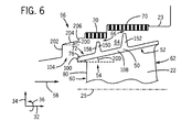
- FIG. 6 is a partial side view of an embodiment of the turbine blade 22 and the stationary structural component 23, illustrating the tip shroud 50 disposed on the outer radial end 52 of the turbine blade 22, where the tip shroud 50 includes the labyrinth seal 66 having two rails 68 (e.g., the first rail 150 and the second rail 152) and two honeycomb inserts 70 (e.g., casing abradable surfaces), and the leading edge portion 54 of the tip shroud 50 and the corresponding portion 56 of the stationary structural component 23 have a generally parallel configuration. Additionally, in the illustrated embodiment, the nose portion 72 of the tip shroud 50 is collinear with the remaining portion of the tip shroud 50 (i.e., the portion of the tip shroud 50 not including the nose portion 72).
- the tip shroud 50 includes the labyrinth seal 66 having two rails 68 (e.g., the first rail 150 and the second rail 152) and two honeycomb inserts 70 (e.g., casing abradable surfaces), and the
- the entire tip shroud 50 is oriented at an angle 200 relative to the rotational axis 25 of the turbine 18.
- the leading edge portion 54 of the tip shroud 50 generally refers to the portion of the tip shroud 50 upstream of the first rail 150 of the labyrinth seal 66.
- leading edge 100 of the leading edge overhang 78 corresponds with a first corresponding portion 202 of the stationary structural component 23.
- the leading edge 100 of the leading edge overhang 78 and the first corresponding portion 202 each extend generally in the radial direction 34.
- the first corresponding portion 202 of the stationary structural component 23 is disposed generally upstream from the leading edge 100 of the leading edge overhang 78, thereby creating the opening 104 of the clearance 64 between the tip shroud 50 and the stationary structural component 23.
- the nose portion 72 of the tip shroud 50 and the second corresponding portion 204 of the stationary structural component 23 are disposed generally opposite one another across the clearance 64 between the tip shroud 50 and the stationary structural component 23. In this manner, the nose portion 72 of the tip shroud 50 and the second corresponding portion 204 of the stationary structural component 23 are arranged in a generally parallel configuration. In other words, the contours (e.g., surfaces) of the nose portion 72 of the tip shroud 50 and the second corresponding portion 204 of the stationary structural component 23 are generally parallel with one another.
- the tip shroud 50 includes the first rail 150 of the labyrinth seal 66, which generally extends in the radial direction 34.
- the first rail 150 has the upstream surface 158, which is generally vertical.
- the upstream surface 158 of the first rail 150 extends generally in the radial direction 34.
- the upstream surface 158 of the first rail 150 corresponds to a third corresponding portion 206 of the stationary structural component 23.
- the third corresponding portion 206 also extends generally in the radial direction 34 (i.e., the third corresponding portion 206 is generally vertical).
- the first corresponding portion 202 of the stationary structural component 23, the second corresponding portion 204 of the stationary structural component 23, and the third corresponding portion 206 of the stationary structural component 23 are arranged in consecutive order along the stationary structural component 23 in the axial direction 32, with the first corresponding portion 202 of the stationary structural component 23 being the most upstream.
- leading edge portion 54 of the tip shroud 50 and the corresponding portion 56 of the stationary structural component 23 are arranged in a generally parallel configuration.
- the generally parallel configuration of the leading edge portion 54 of the tip shroud 50 and the corresponding portion 56 of the stationary structural component 23 may help reduce leakage of the fluid flow 58 through the clearance 64 between the tip shroud 50 and the stationary structural component 23. Additionally, the generally parallel configuration may help reduce the generation of vortex flows within the clearance 64.
- the generally parallel configuration between the leading edge portion 54 of the tip shroud 50 and the corresponding portion 56 of the stationary structural component 23 may provide a more tailored and/or reduced clearance 64 between the tip shroud 50 and the stationary structural component 23, resulting in increased blockage of the fluid flow 58 through the clearance 64.
- embodiments of the present disclosure include the tip shroud 50 of the turbine blade 22 arranged in a generally parallel configuration with the stationary structural component 23 of the turbine 18. Specifically, the leading edge portion 54 of the tip shroud 50 and the corresponding portion 56 of the stationary structural component 23 are arranged in a generally parallel configuration relative to one another. The generally parallel configuration between the leading edge portion 54 of the tip shroud 50 and the corresponding portion 56 of the stationary structural component 23 may reduce flow leakage through the clearance 64 between the tip shroud 50 and the stationary structural component 23.
- the generally parallel configuration between the leading edge portion 54 of the tip shroud 50 and the corresponding portion 56 of the stationary structural component 23 may provide a more tailored clearance 64 between the tip shroud 50 and the stationary structural component 23, resulting in reduction of leakage of the fluid flow 58 through the clearance 64.
- a turbomachine such as the turbine 18, having the described generally parallel arrangement between the leading edge portion 54 of the tip shroud 50 and the corresponding portion 56 of the stationary structural component 23 may experience improved performance and efficiency.
Landscapes
- Engineering & Computer Science (AREA)
- Mechanical Engineering (AREA)
- General Engineering & Computer Science (AREA)
- Turbine Rotor Nozzle Sealing (AREA)
- Sealing Using Fluids, Sealing Without Contact, And Removal Of Oil (AREA)
Applications Claiming Priority (1)
| Application Number | Priority Date | Filing Date | Title |
|---|---|---|---|
| US13/447,134 US9291061B2 (en) | 2012-04-13 | 2012-04-13 | Turbomachine blade tip shroud with parallel casing configuration |
Publications (3)
| Publication Number | Publication Date |
|---|---|
| EP2650476A2 true EP2650476A2 (fr) | 2013-10-16 |
| EP2650476A3 EP2650476A3 (fr) | 2015-08-26 |
| EP2650476B1 EP2650476B1 (fr) | 2020-10-07 |
Family
ID=48087431
Family Applications (1)
| Application Number | Title | Priority Date | Filing Date |
|---|---|---|---|
| EP13163003.0A Active EP2650476B1 (fr) | 2012-04-13 | 2013-04-09 | Virole d'extrémité de pales de turbomachine avec configuration de carter parallèle |
Country Status (5)
| Country | Link |
|---|---|
| US (1) | US9291061B2 (fr) |
| EP (1) | EP2650476B1 (fr) |
| JP (1) | JP6145296B2 (fr) |
| CN (1) | CN103375185B (fr) |
| RU (1) | RU2013116442A (fr) |
Cited By (1)
| Publication number | Priority date | Publication date | Assignee | Title |
|---|---|---|---|---|
| FR3065483A1 (fr) * | 2017-04-24 | 2018-10-26 | Safran Aircraft Engines | Dispositif d'etancheite entre rotor et stator de turbomachine |
Families Citing this family (14)
| Publication number | Priority date | Publication date | Assignee | Title |
|---|---|---|---|---|
| EP2647796A1 (fr) * | 2012-04-04 | 2013-10-09 | MTU Aero Engines GmbH | Système d'étanchéité pour turbomachine |
| JP5972374B2 (ja) * | 2012-07-11 | 2016-08-17 | 三菱日立パワーシステムズ株式会社 | 軸流流体機械 |
| JP5567077B2 (ja) * | 2012-08-23 | 2014-08-06 | 三菱重工業株式会社 | 回転機械 |
| JP6131177B2 (ja) * | 2013-12-03 | 2017-05-17 | 三菱重工業株式会社 | シール構造、及び回転機械 |
| US20180179901A1 (en) * | 2015-07-24 | 2018-06-28 | Siemens Aktiengesellschaft | Turbine blade with contoured tip shroud |
| US10808539B2 (en) * | 2016-07-25 | 2020-10-20 | Raytheon Technologies Corporation | Rotor blade for a gas turbine engine |
| DE102016222720A1 (de) * | 2016-11-18 | 2018-05-24 | MTU Aero Engines AG | Dichtungssystem für eine axiale Strömungsmaschine und axiale Strömungsmaschine |
| JP6782671B2 (ja) * | 2017-07-10 | 2020-11-11 | 三菱重工業株式会社 | ターボ機械 |
| US10815811B2 (en) * | 2017-11-28 | 2020-10-27 | General Electric Company | Rotatable component for turbomachines, including a non-axisymmetric overhanging portion |
| JP7061497B2 (ja) * | 2018-03-30 | 2022-04-28 | 三菱重工航空エンジン株式会社 | 航空機用ガスタービン |
| PL430870A1 (pl) | 2019-08-14 | 2021-02-22 | Avio Polska Spółka Z Ograniczoną Odpowiedzialnością | Uszczelnienie do zmniejszania wycieku przepływu wewnątrz silnika z turbiną gazową |
| JP7519201B2 (ja) * | 2020-03-31 | 2024-07-19 | 川崎重工業株式会社 | ラビリンスシール及びガスタービン |
| CN114776389B (zh) * | 2022-03-16 | 2024-03-12 | 北京航空航天大学 | 一种具有缘板台阶机匣的带冠涡轮 |
| US20250382893A1 (en) * | 2024-06-14 | 2025-12-18 | Pratt & Whitney Canada Corp. | Shrouded turbine assembly for gas turbine engine |
Family Cites Families (32)
| Publication number | Priority date | Publication date | Assignee | Title |
|---|---|---|---|---|
| US783572A (en) | 1904-11-29 | 1905-02-28 | Columbia Nut And Bolt Company | Nut-lock. |
| US1235205A (en) | 1916-10-30 | 1917-07-31 | James S Kierstead | Nut-lock. |
| US1470528A (en) | 1921-06-11 | 1923-10-09 | Flentjen Auguste | Lock screw |
| GB1423833A (en) | 1972-04-20 | 1976-02-04 | Rolls Royce | Rotor blades for fluid flow machines |
| US4687413A (en) * | 1985-07-31 | 1987-08-18 | United Technologies Corporation | Gas turbine engine assembly |
| GB2228540B (en) | 1988-12-07 | 1993-03-31 | Rolls Royce Plc | Cooling of turbine blades |
| US5228195A (en) * | 1990-09-25 | 1993-07-20 | United Technologies Corporation | Apparatus and method for a stator assembly of a rotary machine |
| GB2249356B (en) * | 1990-11-01 | 1995-01-18 | Rolls Royce Plc | Shroud liners |
| US5156525A (en) * | 1991-02-26 | 1992-10-20 | General Electric Company | Turbine assembly |
| DE59201833D1 (de) * | 1991-10-08 | 1995-05-11 | Asea Brown Boveri | Deckband für axialdurchströmte Turbine. |
| US5632598A (en) * | 1995-01-17 | 1997-05-27 | Dresser-Rand | Shrouded axial flow turbo machine utilizing multiple labrinth seals |
| EP0903468B1 (fr) * | 1997-09-19 | 2003-08-20 | ALSTOM (Switzerland) Ltd | Dispositif d'étanchéité pour un interstice |
| US5971710A (en) * | 1997-10-17 | 1999-10-26 | United Technologies Corporation | Turbomachinery blade or vane with a permanent machining datum |
| JP3794868B2 (ja) * | 1999-06-15 | 2006-07-12 | 三菱重工業株式会社 | ガスタービン静翼 |
| GB9915648D0 (en) | 1999-07-06 | 1999-09-01 | Rolls Royce Plc | Improvement in or relating to turbine blades |
| GB0029337D0 (en) * | 2000-12-01 | 2001-01-17 | Rolls Royce Plc | A seal segment for a turbine |
| US6652226B2 (en) * | 2001-02-09 | 2003-11-25 | General Electric Co. | Methods and apparatus for reducing seal teeth wear |
| US6508624B2 (en) * | 2001-05-02 | 2003-01-21 | Siemens Automotive, Inc. | Turbomachine with double-faced rotor-shroud seal structure |
| FR2829176B1 (fr) * | 2001-08-30 | 2005-06-24 | Snecma Moteurs | Carter de stator de turbomachine |
| EP1435432B1 (fr) * | 2001-10-10 | 2016-05-18 | Mitsubishi Hitachi Power Systems, Ltd. | Aube de turbine |
| FR2835563B1 (fr) * | 2002-02-07 | 2004-04-02 | Snecma Moteurs | Agencement d'accrochage de secteurs en arc de cercle de distributeur porteur d'aubes |
| US7048496B2 (en) * | 2002-10-31 | 2006-05-23 | General Electric Company | Turbine cooling, purge, and sealing system |
| US6962043B2 (en) | 2003-01-30 | 2005-11-08 | General Electric Company | Method and apparatus for monitoring the performance of a gas turbine system |
| US6784597B1 (en) | 2003-04-15 | 2004-08-31 | General Electric Company | Self-locking nut for stud shaft and stacked wheel assembly for the rotor of a rotary machine |
| GB2409247A (en) * | 2003-12-20 | 2005-06-22 | Rolls Royce Plc | A seal arrangement |
| US7784263B2 (en) | 2006-12-05 | 2010-08-31 | General Electric Company | Method for determining sensor locations |
| CN100425846C (zh) | 2006-12-22 | 2008-10-15 | 魏民 | 偏心式自锁螺母 |
| JP2010053745A (ja) | 2008-08-27 | 2010-03-11 | Toyota Motor Corp | ガスタービン排気温度検出装置 |
| US20110070072A1 (en) * | 2009-09-23 | 2011-03-24 | General Electric Company | Rotary machine tip clearance control mechanism |
| DE102009042857A1 (de) | 2009-09-24 | 2011-03-31 | Rolls-Royce Deutschland Ltd & Co Kg | Gasturbine mit Deckband-Labyrinthdichtung |
| FR2961846B1 (fr) * | 2010-06-28 | 2012-08-03 | Snecma Propulsion Solide | Aube de turbomachine a geometrie asymetrique complementaire |
| CN102094886B (zh) | 2011-01-20 | 2013-01-23 | 宁波信泰机械有限公司 | 螺栓连接结构及其止动垫圈与行李架 |
-
2012
- 2012-04-13 US US13/447,134 patent/US9291061B2/en active Active
-
2013
- 2013-04-09 EP EP13163003.0A patent/EP2650476B1/fr active Active
- 2013-04-11 JP JP2013082582A patent/JP6145296B2/ja active Active
- 2013-04-11 RU RU2013116442/06A patent/RU2013116442A/ru not_active Application Discontinuation
- 2013-04-12 CN CN201310127344.4A patent/CN103375185B/zh active Active
Cited By (3)
| Publication number | Priority date | Publication date | Assignee | Title |
|---|---|---|---|---|
| FR3065483A1 (fr) * | 2017-04-24 | 2018-10-26 | Safran Aircraft Engines | Dispositif d'etancheite entre rotor et stator de turbomachine |
| WO2018197800A1 (fr) * | 2017-04-24 | 2018-11-01 | Safran Aircraft Engines | Dispositif d'étanchéité entre rotor et stator de turbomachine |
| US11441442B2 (en) | 2017-04-24 | 2022-09-13 | Safran Aircraft Engines | Device for sealing between a rotor and a stator of a turbine engine |
Also Published As
| Publication number | Publication date |
|---|---|
| JP6145296B2 (ja) | 2017-06-07 |
| EP2650476A3 (fr) | 2015-08-26 |
| US9291061B2 (en) | 2016-03-22 |
| CN103375185A (zh) | 2013-10-30 |
| CN103375185B (zh) | 2017-07-07 |
| RU2013116442A (ru) | 2014-10-20 |
| US20130272888A1 (en) | 2013-10-17 |
| JP2013221512A (ja) | 2013-10-28 |
| EP2650476B1 (fr) | 2020-10-07 |
Similar Documents
| Publication | Publication Date | Title |
|---|---|---|
| US9291061B2 (en) | Turbomachine blade tip shroud with parallel casing configuration | |
| CN109519224B (zh) | 包括涡轮转子组件的燃气涡轮发动机 | |
| US10253638B2 (en) | Turbomachine blade tip shroud | |
| CN106948867B (zh) | 带护罩的涡轮转子叶片 | |
| CN106917643B (zh) | 带护罩的涡轮转子叶片 | |
| US8371816B2 (en) | Rotor blades for turbine engines | |
| US8894376B2 (en) | Turbomachine blade with tip flare | |
| CN103184900B (zh) | 用于涡轮护罩的向前台阶蜂巢式密封件 | |
| US9097136B2 (en) | Contoured honeycomb seal for turbine shroud | |
| EP3693541B1 (fr) | Disque de rotor de turbine à gaz doté d'une fonctionnalité de protection de grille | |
| US11060407B2 (en) | Turbomachine rotor blade | |
| US10138736B2 (en) | Turbomachine blade tip shroud | |
| EP3284917B1 (fr) | Collecteur de contrôle de jeu actif pour insert de collecteur | |
| US9593691B2 (en) | Systems and methods for directing a flow within a shroud cavity of a compressor | |
| US10837300B2 (en) | Seal pressurization in box shroud |
Legal Events
| Date | Code | Title | Description |
|---|---|---|---|
| PUAI | Public reference made under article 153(3) epc to a published international application that has entered the european phase |
Free format text: ORIGINAL CODE: 0009012 |
|
| AK | Designated contracting states |
Kind code of ref document: A2 Designated state(s): AL AT BE BG CH CY CZ DE DK EE ES FI FR GB GR HR HU IE IS IT LI LT LU LV MC MK MT NL NO PL PT RO RS SE SI SK SM TR |
|
| AX | Request for extension of the european patent |
Extension state: BA ME |
|
| PUAL | Search report despatched |
Free format text: ORIGINAL CODE: 0009013 |
|
| AK | Designated contracting states |
Kind code of ref document: A3 Designated state(s): AL AT BE BG CH CY CZ DE DK EE ES FI FR GB GR HR HU IE IS IT LI LT LU LV MC MK MT NL NO PL PT RO RS SE SI SK SM TR |
|
| AX | Request for extension of the european patent |
Extension state: BA ME |
|
| RIC1 | Information provided on ipc code assigned before grant |
Ipc: F01D 5/22 20060101AFI20150723BHEP Ipc: F01D 11/08 20060101ALI20150723BHEP |
|
| 17P | Request for examination filed |
Effective date: 20160226 |
|
| RBV | Designated contracting states (corrected) |
Designated state(s): AL AT BE BG CH CY CZ DE DK EE ES FI FR GB GR HR HU IE IS IT LI LT LU LV MC MK MT NL NO PL PT RO RS SE SI SK SM TR |
|
| STAA | Information on the status of an ep patent application or granted ep patent |
Free format text: STATUS: EXAMINATION IS IN PROGRESS |
|
| 17Q | First examination report despatched |
Effective date: 20171005 |
|
| GRAP | Despatch of communication of intention to grant a patent |
Free format text: ORIGINAL CODE: EPIDOSNIGR1 |
|
| STAA | Information on the status of an ep patent application or granted ep patent |
Free format text: STATUS: GRANT OF PATENT IS INTENDED |
|
| INTG | Intention to grant announced |
Effective date: 20191127 |
|
| GRAJ | Information related to disapproval of communication of intention to grant by the applicant or resumption of examination proceedings by the epo deleted |
Free format text: ORIGINAL CODE: EPIDOSDIGR1 |
|
| STAA | Information on the status of an ep patent application or granted ep patent |
Free format text: STATUS: EXAMINATION IS IN PROGRESS |
|
| INTC | Intention to grant announced (deleted) | ||
| GRAP | Despatch of communication of intention to grant a patent |
Free format text: ORIGINAL CODE: EPIDOSNIGR1 |
|
| STAA | Information on the status of an ep patent application or granted ep patent |
Free format text: STATUS: GRANT OF PATENT IS INTENDED |
|
| INTG | Intention to grant announced |
Effective date: 20200507 |
|
| GRAS | Grant fee paid |
Free format text: ORIGINAL CODE: EPIDOSNIGR3 |
|
| GRAA | (expected) grant |
Free format text: ORIGINAL CODE: 0009210 |
|
| STAA | Information on the status of an ep patent application or granted ep patent |
Free format text: STATUS: THE PATENT HAS BEEN GRANTED |
|
| AK | Designated contracting states |
Kind code of ref document: B1 Designated state(s): AL AT BE BG CH CY CZ DE DK EE ES FI FR GB GR HR HU IE IS IT LI LT LU LV MC MK MT NL NO PL PT RO RS SE SI SK SM TR |
|
| REG | Reference to a national code |
Ref country code: GB Ref legal event code: FG4D |
|
| REG | Reference to a national code |
Ref country code: CH Ref legal event code: EP Ref country code: AT Ref legal event code: REF Ref document number: 1321352 Country of ref document: AT Kind code of ref document: T Effective date: 20201015 |
|
| REG | Reference to a national code |
Ref country code: IE Ref legal event code: FG4D |
|
| REG | Reference to a national code |
Ref country code: DE Ref legal event code: R096 Ref document number: 602013073046 Country of ref document: DE |
|
| REG | Reference to a national code |
Ref country code: NL Ref legal event code: MP Effective date: 20201007 |
|
| REG | Reference to a national code |
Ref country code: AT Ref legal event code: MK05 Ref document number: 1321352 Country of ref document: AT Kind code of ref document: T Effective date: 20201007 |
|
| PG25 | Lapsed in a contracting state [announced via postgrant information from national office to epo] |
Ref country code: NL Free format text: LAPSE BECAUSE OF FAILURE TO SUBMIT A TRANSLATION OF THE DESCRIPTION OR TO PAY THE FEE WITHIN THE PRESCRIBED TIME-LIMIT Effective date: 20201007 Ref country code: NO Free format text: LAPSE BECAUSE OF FAILURE TO SUBMIT A TRANSLATION OF THE DESCRIPTION OR TO PAY THE FEE WITHIN THE PRESCRIBED TIME-LIMIT Effective date: 20210107 Ref country code: PT Free format text: LAPSE BECAUSE OF FAILURE TO SUBMIT A TRANSLATION OF THE DESCRIPTION OR TO PAY THE FEE WITHIN THE PRESCRIBED TIME-LIMIT Effective date: 20210208 Ref country code: FI Free format text: LAPSE BECAUSE OF FAILURE TO SUBMIT A TRANSLATION OF THE DESCRIPTION OR TO PAY THE FEE WITHIN THE PRESCRIBED TIME-LIMIT Effective date: 20201007 Ref country code: RS Free format text: LAPSE BECAUSE OF FAILURE TO SUBMIT A TRANSLATION OF THE DESCRIPTION OR TO PAY THE FEE WITHIN THE PRESCRIBED TIME-LIMIT Effective date: 20201007 Ref country code: GR Free format text: LAPSE BECAUSE OF FAILURE TO SUBMIT A TRANSLATION OF THE DESCRIPTION OR TO PAY THE FEE WITHIN THE PRESCRIBED TIME-LIMIT Effective date: 20210108 |
|
| REG | Reference to a national code |
Ref country code: LT Ref legal event code: MG4D |
|
| PG25 | Lapsed in a contracting state [announced via postgrant information from national office to epo] |
Ref country code: AT Free format text: LAPSE BECAUSE OF FAILURE TO SUBMIT A TRANSLATION OF THE DESCRIPTION OR TO PAY THE FEE WITHIN THE PRESCRIBED TIME-LIMIT Effective date: 20201007 Ref country code: ES Free format text: LAPSE BECAUSE OF FAILURE TO SUBMIT A TRANSLATION OF THE DESCRIPTION OR TO PAY THE FEE WITHIN THE PRESCRIBED TIME-LIMIT Effective date: 20201007 Ref country code: BG Free format text: LAPSE BECAUSE OF FAILURE TO SUBMIT A TRANSLATION OF THE DESCRIPTION OR TO PAY THE FEE WITHIN THE PRESCRIBED TIME-LIMIT Effective date: 20210107 Ref country code: LV Free format text: LAPSE BECAUSE OF FAILURE TO SUBMIT A TRANSLATION OF THE DESCRIPTION OR TO PAY THE FEE WITHIN THE PRESCRIBED TIME-LIMIT Effective date: 20201007 Ref country code: IS Free format text: LAPSE BECAUSE OF FAILURE TO SUBMIT A TRANSLATION OF THE DESCRIPTION OR TO PAY THE FEE WITHIN THE PRESCRIBED TIME-LIMIT Effective date: 20210207 Ref country code: SE Free format text: LAPSE BECAUSE OF FAILURE TO SUBMIT A TRANSLATION OF THE DESCRIPTION OR TO PAY THE FEE WITHIN THE PRESCRIBED TIME-LIMIT Effective date: 20201007 Ref country code: PL Free format text: LAPSE BECAUSE OF FAILURE TO SUBMIT A TRANSLATION OF THE DESCRIPTION OR TO PAY THE FEE WITHIN THE PRESCRIBED TIME-LIMIT Effective date: 20201007 |
|
| PG25 | Lapsed in a contracting state [announced via postgrant information from national office to epo] |
Ref country code: HR Free format text: LAPSE BECAUSE OF FAILURE TO SUBMIT A TRANSLATION OF THE DESCRIPTION OR TO PAY THE FEE WITHIN THE PRESCRIBED TIME-LIMIT Effective date: 20201007 |
|
| REG | Reference to a national code |
Ref country code: DE Ref legal event code: R097 Ref document number: 602013073046 Country of ref document: DE |
|
| PG25 | Lapsed in a contracting state [announced via postgrant information from national office to epo] |
Ref country code: CZ Free format text: LAPSE BECAUSE OF FAILURE TO SUBMIT A TRANSLATION OF THE DESCRIPTION OR TO PAY THE FEE WITHIN THE PRESCRIBED TIME-LIMIT Effective date: 20201007 Ref country code: EE Free format text: LAPSE BECAUSE OF FAILURE TO SUBMIT A TRANSLATION OF THE DESCRIPTION OR TO PAY THE FEE WITHIN THE PRESCRIBED TIME-LIMIT Effective date: 20201007 Ref country code: SM Free format text: LAPSE BECAUSE OF FAILURE TO SUBMIT A TRANSLATION OF THE DESCRIPTION OR TO PAY THE FEE WITHIN THE PRESCRIBED TIME-LIMIT Effective date: 20201007 Ref country code: RO Free format text: LAPSE BECAUSE OF FAILURE TO SUBMIT A TRANSLATION OF THE DESCRIPTION OR TO PAY THE FEE WITHIN THE PRESCRIBED TIME-LIMIT Effective date: 20201007 Ref country code: SK Free format text: LAPSE BECAUSE OF FAILURE TO SUBMIT A TRANSLATION OF THE DESCRIPTION OR TO PAY THE FEE WITHIN THE PRESCRIBED TIME-LIMIT Effective date: 20201007 Ref country code: LT Free format text: LAPSE BECAUSE OF FAILURE TO SUBMIT A TRANSLATION OF THE DESCRIPTION OR TO PAY THE FEE WITHIN THE PRESCRIBED TIME-LIMIT Effective date: 20201007 |
|
| PLBE | No opposition filed within time limit |
Free format text: ORIGINAL CODE: 0009261 |
|
| STAA | Information on the status of an ep patent application or granted ep patent |
Free format text: STATUS: NO OPPOSITION FILED WITHIN TIME LIMIT |
|
| PG25 | Lapsed in a contracting state [announced via postgrant information from national office to epo] |
Ref country code: DK Free format text: LAPSE BECAUSE OF FAILURE TO SUBMIT A TRANSLATION OF THE DESCRIPTION OR TO PAY THE FEE WITHIN THE PRESCRIBED TIME-LIMIT Effective date: 20201007 |
|
| 26N | No opposition filed |
Effective date: 20210708 |
|
| PG25 | Lapsed in a contracting state [announced via postgrant information from national office to epo] |
Ref country code: AL Free format text: LAPSE BECAUSE OF FAILURE TO SUBMIT A TRANSLATION OF THE DESCRIPTION OR TO PAY THE FEE WITHIN THE PRESCRIBED TIME-LIMIT Effective date: 20201007 Ref country code: IT Free format text: LAPSE BECAUSE OF FAILURE TO SUBMIT A TRANSLATION OF THE DESCRIPTION OR TO PAY THE FEE WITHIN THE PRESCRIBED TIME-LIMIT Effective date: 20201007 |
|
| PG25 | Lapsed in a contracting state [announced via postgrant information from national office to epo] |
Ref country code: MC Free format text: LAPSE BECAUSE OF FAILURE TO SUBMIT A TRANSLATION OF THE DESCRIPTION OR TO PAY THE FEE WITHIN THE PRESCRIBED TIME-LIMIT Effective date: 20201007 Ref country code: SI Free format text: LAPSE BECAUSE OF FAILURE TO SUBMIT A TRANSLATION OF THE DESCRIPTION OR TO PAY THE FEE WITHIN THE PRESCRIBED TIME-LIMIT Effective date: 20201007 |
|
| GBPC | Gb: european patent ceased through non-payment of renewal fee |
Effective date: 20210409 |
|
| PG25 | Lapsed in a contracting state [announced via postgrant information from national office to epo] |
Ref country code: LU Free format text: LAPSE BECAUSE OF NON-PAYMENT OF DUE FEES Effective date: 20210409 |
|
| REG | Reference to a national code |
Ref country code: BE Ref legal event code: MM Effective date: 20210430 |
|
| PG25 | Lapsed in a contracting state [announced via postgrant information from national office to epo] |
Ref country code: FR Free format text: LAPSE BECAUSE OF NON-PAYMENT OF DUE FEES Effective date: 20210430 Ref country code: GB Free format text: LAPSE BECAUSE OF NON-PAYMENT OF DUE FEES Effective date: 20210409 Ref country code: CH Free format text: LAPSE BECAUSE OF NON-PAYMENT OF DUE FEES Effective date: 20210430 Ref country code: LI Free format text: LAPSE BECAUSE OF NON-PAYMENT OF DUE FEES Effective date: 20210430 |
|
| PG25 | Lapsed in a contracting state [announced via postgrant information from national office to epo] |
Ref country code: IE Free format text: LAPSE BECAUSE OF NON-PAYMENT OF DUE FEES Effective date: 20210409 |
|
| PG25 | Lapsed in a contracting state [announced via postgrant information from national office to epo] |
Ref country code: IS Free format text: LAPSE BECAUSE OF FAILURE TO SUBMIT A TRANSLATION OF THE DESCRIPTION OR TO PAY THE FEE WITHIN THE PRESCRIBED TIME-LIMIT Effective date: 20210207 |
|
| PG25 | Lapsed in a contracting state [announced via postgrant information from national office to epo] |
Ref country code: BE Free format text: LAPSE BECAUSE OF NON-PAYMENT OF DUE FEES Effective date: 20210430 |
|
| PG25 | Lapsed in a contracting state [announced via postgrant information from national office to epo] |
Ref country code: HU Free format text: LAPSE BECAUSE OF FAILURE TO SUBMIT A TRANSLATION OF THE DESCRIPTION OR TO PAY THE FEE WITHIN THE PRESCRIBED TIME-LIMIT; INVALID AB INITIO Effective date: 20130409 |
|
| PG25 | Lapsed in a contracting state [announced via postgrant information from national office to epo] |
Ref country code: CY Free format text: LAPSE BECAUSE OF FAILURE TO SUBMIT A TRANSLATION OF THE DESCRIPTION OR TO PAY THE FEE WITHIN THE PRESCRIBED TIME-LIMIT Effective date: 20201007 |
|
| REG | Reference to a national code |
Ref country code: DE Ref legal event code: R081 Ref document number: 602013073046 Country of ref document: DE Owner name: GENERAL ELECTRIC TECHNOLOGY GMBH, CH Free format text: FORMER OWNER: GENERAL ELECTRIC COMPANY, SCHENECTADY, NY, US |
|
| PG25 | Lapsed in a contracting state [announced via postgrant information from national office to epo] |
Ref country code: MK Free format text: LAPSE BECAUSE OF FAILURE TO SUBMIT A TRANSLATION OF THE DESCRIPTION OR TO PAY THE FEE WITHIN THE PRESCRIBED TIME-LIMIT Effective date: 20201007 |
|
| PG25 | Lapsed in a contracting state [announced via postgrant information from national office to epo] |
Ref country code: MT Free format text: LAPSE BECAUSE OF FAILURE TO SUBMIT A TRANSLATION OF THE DESCRIPTION OR TO PAY THE FEE WITHIN THE PRESCRIBED TIME-LIMIT Effective date: 20201007 |
|
| PGFP | Annual fee paid to national office [announced via postgrant information from national office to epo] |
Ref country code: DE Payment date: 20250319 Year of fee payment: 13 |
|
| PG25 | Lapsed in a contracting state [announced via postgrant information from national office to epo] |
Ref country code: TR Free format text: LAPSE BECAUSE OF FAILURE TO SUBMIT A TRANSLATION OF THE DESCRIPTION OR TO PAY THE FEE WITHIN THE PRESCRIBED TIME-LIMIT Effective date: 20201007 |