EP2650962A1 - Système de support d'antenne - Google Patents
Système de support d'antenne Download PDFInfo
- Publication number
- EP2650962A1 EP2650962A1 EP12163860.5A EP12163860A EP2650962A1 EP 2650962 A1 EP2650962 A1 EP 2650962A1 EP 12163860 A EP12163860 A EP 12163860A EP 2650962 A1 EP2650962 A1 EP 2650962A1
- Authority
- EP
- European Patent Office
- Prior art keywords
- antenna
- support system
- orientation
- pitch
- platform
- Prior art date
- Legal status (The legal status is an assumption and is not a legal conclusion. Google has not performed a legal analysis and makes no representation as to the accuracy of the status listed.)
- Withdrawn
Links
- 230000000087 stabilizing effect Effects 0.000 claims abstract description 46
- 230000004044 response Effects 0.000 claims abstract description 7
- 238000013016 damping Methods 0.000 claims description 39
- 230000010287 polarization Effects 0.000 claims description 18
- 238000004891 communication Methods 0.000 description 10
- 230000001133 acceleration Effects 0.000 description 5
- 230000008859 change Effects 0.000 description 3
- 230000035939 shock Effects 0.000 description 3
- 239000006096 absorbing agent Substances 0.000 description 2
- 230000008901 benefit Effects 0.000 description 2
- 230000000694 effects Effects 0.000 description 2
- 230000004075 alteration Effects 0.000 description 1
- 230000008878 coupling Effects 0.000 description 1
- 238000010168 coupling process Methods 0.000 description 1
- 238000005859 coupling reaction Methods 0.000 description 1
- 230000001419 dependent effect Effects 0.000 description 1
- 238000001514 detection method Methods 0.000 description 1
- 230000001627 detrimental effect Effects 0.000 description 1
- 238000004146 energy storage Methods 0.000 description 1
- 230000005484 gravity Effects 0.000 description 1
- 238000002955 isolation Methods 0.000 description 1
- 239000000463 material Substances 0.000 description 1
- 230000004048 modification Effects 0.000 description 1
- 238000012986 modification Methods 0.000 description 1
- 239000004033 plastic Substances 0.000 description 1
- 230000009467 reduction Effects 0.000 description 1
Images




Classifications
-
- F—MECHANICAL ENGINEERING; LIGHTING; HEATING; WEAPONS; BLASTING
- F16—ENGINEERING ELEMENTS AND UNITS; GENERAL MEASURES FOR PRODUCING AND MAINTAINING EFFECTIVE FUNCTIONING OF MACHINES OR INSTALLATIONS; THERMAL INSULATION IN GENERAL
- F16M—FRAMES, CASINGS OR BEDS OF ENGINES, MACHINES OR APPARATUS, NOT SPECIFIC TO ENGINES, MACHINES OR APPARATUS PROVIDED FOR ELSEWHERE; STANDS; SUPPORTS
- F16M11/00—Stands or trestles as supports for apparatus or articles placed thereon ; Stands for scientific apparatus such as gravitational force meters
- F16M11/20—Undercarriages with or without wheels
- F16M11/2007—Undercarriages with or without wheels comprising means allowing pivoting adjustment
- F16M11/2035—Undercarriages with or without wheels comprising means allowing pivoting adjustment in more than one direction
- F16M11/2071—Undercarriages with or without wheels comprising means allowing pivoting adjustment in more than one direction for panning and rolling
-
- F—MECHANICAL ENGINEERING; LIGHTING; HEATING; WEAPONS; BLASTING
- F16—ENGINEERING ELEMENTS AND UNITS; GENERAL MEASURES FOR PRODUCING AND MAINTAINING EFFECTIVE FUNCTIONING OF MACHINES OR INSTALLATIONS; THERMAL INSULATION IN GENERAL
- F16M—FRAMES, CASINGS OR BEDS OF ENGINES, MACHINES OR APPARATUS, NOT SPECIFIC TO ENGINES, MACHINES OR APPARATUS PROVIDED FOR ELSEWHERE; STANDS; SUPPORTS
- F16M11/00—Stands or trestles as supports for apparatus or articles placed thereon ; Stands for scientific apparatus such as gravitational force meters
- F16M11/02—Heads
- F16M11/04—Means for attachment of apparatus; Means allowing adjustment of the apparatus relatively to the stand
- F16M11/06—Means for attachment of apparatus; Means allowing adjustment of the apparatus relatively to the stand allowing pivoting
- F16M11/10—Means for attachment of apparatus; Means allowing adjustment of the apparatus relatively to the stand allowing pivoting around a horizontal axis
-
- F—MECHANICAL ENGINEERING; LIGHTING; HEATING; WEAPONS; BLASTING
- F16—ENGINEERING ELEMENTS AND UNITS; GENERAL MEASURES FOR PRODUCING AND MAINTAINING EFFECTIVE FUNCTIONING OF MACHINES OR INSTALLATIONS; THERMAL INSULATION IN GENERAL
- F16M—FRAMES, CASINGS OR BEDS OF ENGINES, MACHINES OR APPARATUS, NOT SPECIFIC TO ENGINES, MACHINES OR APPARATUS PROVIDED FOR ELSEWHERE; STANDS; SUPPORTS
- F16M11/00—Stands or trestles as supports for apparatus or articles placed thereon ; Stands for scientific apparatus such as gravitational force meters
- F16M11/02—Heads
- F16M11/18—Heads with mechanism for moving the apparatus relatively to the stand
-
- H—ELECTRICITY
- H01—ELECTRIC ELEMENTS
- H01Q—ANTENNAS, i.e. RADIO AERIALS
- H01Q1/00—Details of, or arrangements associated with, antennas
- H01Q1/12—Supports; Mounting means
- H01Q1/18—Means for stabilising antennas on an unstable platform
- H01Q1/185—Means for stabilising antennas on an unstable platform by electronic means
-
- H—ELECTRICITY
- H01—ELECTRIC ELEMENTS
- H01Q—ANTENNAS, i.e. RADIO AERIALS
- H01Q1/00—Details of, or arrangements associated with, antennas
- H01Q1/27—Adaptation for use in or on movable bodies
- H01Q1/34—Adaptation for use in or on ships, submarines, buoys or torpedoes
-
- H—ELECTRICITY
- H01—ELECTRIC ELEMENTS
- H01Q—ANTENNAS, i.e. RADIO AERIALS
- H01Q3/00—Arrangements for changing or varying the orientation or the shape of the directional pattern of the waves radiated from an antenna or antenna system
- H01Q3/02—Arrangements for changing or varying the orientation or the shape of the directional pattern of the waves radiated from an antenna or antenna system using mechanical movement of antenna or antenna system as a whole
- H01Q3/08—Arrangements for changing or varying the orientation or the shape of the directional pattern of the waves radiated from an antenna or antenna system using mechanical movement of antenna or antenna system as a whole for varying two co-ordinates of the orientation
Definitions
- the present invention relates to a platform for a satellite antenna.
- the present invention relates to an antenna support system.
- Various types of platforms are used for directing an antenna for satellite communication towards a communication satellite.
- satellite communication antennas mounted on a moving vehicle, it is important that an antenna platform is able to adapt to the movements of the vehicle so that the antenna is always directed at the satellite.
- satellite antennas are commonly used on marine vessels where it is required that an antenna platform is able to compensate for the movements of the vessel.
- an antenna platform comprising three axes, azimuth, elevation, and polarization, may be used to compensate for pitch and roll of the vessel.
- the azimuth and polarization axes may have to work fast to compensate for pitch and roll of the vessel. Furthermore, under some circumstances, the azimuth and polarization axes may be unable to correctly compensate for pitch and roll movements of the vessel.
- an antenna platform introducing a fourth axis arranged orthogonally to the elevation axis may be used.
- An antenna platform comprising a cross axis requires less overall movement when compensating for pitch and roll movements.
- such a four-axis platform still requires that all four axes have high angular velocity and high angular acceleration over the entire effective angular range.
- an antenna platform using four axes still requires high performance components for controlling all four axes which leads to a high cost of the overall platform.
- a general object of the present invention is to provide an improved satellite antenna support system for use on a moving vessel.
- an antenna support system for arrangement on a moving vessel, the antenna support system comprising: a lower stabilizing platform comprising a pitch actuator for controlling movement about a pitch axis of the lower stabilizing platform, and a roll actuator for controlling movement about a roll axis of the lower stabilizing platform; a sensing device configured to detect a pitch orientation and a roll orientation in relation to a horizontal plane; first control circuitry connected to the sensing device and to the pitch actuator and the roll actuator, the first control circuitry being configured to acquire pitch and roll parameters from the sensing device and to control the pitch actuator and the roll actuator to maintain a predetermined orientation of the lower stabilizing platform in relation to the horizontal plane; an upper directing platform attached to the lower stabilizing platform and comprising an antenna orientation arrangement; second control circuitry connected to the antenna orientation arrangement and configured to control an orientation of the antenna orientation arrangement in response to an input signal indicating a desired antenna orientation; wherein the first control circuitry and the second control circuitry operate independently of each other.
- the antenna support system according to the present invention may typically be used for supporting an antenna for satellite communication on a marine vessel.
- the vessel may equally well be an amphibian vessel such as a hovercraft or a landing craft, or a land based vessel where reliable satellite communication is desirable.
- the antenna support system may be particularly useful in land based communication systems such as SOTM (Satcom On The Move) and COTM (Communication On The Move).
- pitch and roll should be understood as the rotation around the x and y axes in xyz space, as defined in a Cartesian coordinate system, where the xy-plane is the horizontal plane.
- the pitch and roll axes are defined in relation to the vessel on which the antenna support is mounted, where roll is defined as rotation around the longitudinal axis and pitch is defined as rotation around the lateral axis of the vessel.
- the antenna support may be arranged in any orientation on the vessel. However it is preferred that the antenna support is mounted essentially aligned with the horizontal plane in order to best utilize the full movement range of the platform. It is typically preferred that the predetermined orientation of the lower stabilizing platform is in alignment with the horizontal plane.
- Both the first and the second control circuitry may each be provided in the form a single control unit.
- a control unit may include a microprocessor, microcontroller, programmable digital signal processor or another programmable device.
- the control unit may also, or instead, include an application specific integrated circuit, a programmable gate array or programmable array logic, a programmable logic device, or a digital signal processor.
- the control unit includes a programmable device such as the microprocessor, microcontroller or programmable digital signal processor mentioned above, the processor may further include computer executable code that controls operation of the programmable device.
- the control circuitry may be configured to communicate with external units through any suitable communication interface such as for example a CAN-bus, Ethernet etc.
- the second control circuitry configured to control the orientation of the antenna orientation arrangement may receive instructions regarding a desired orientation of an antenna connected to the antenna support based on a travel direction of the vessel, a position of the vessel and coordinates of a specific satellite.
- the second control circuitry may receive instructions based on an orientation detection device of the vessel such as a gyroscope.
- the fast movements required to compensate for pitch and roll movements in a four axis platform may lead to excessive wear of the mechanical components in the antenna platform. Thereby, as all four axes are actively engaged in compensating for pitch and roll movements, the mean time between failures (MTBF) for components in such a platform may be low.
- MTBF mean time between failures
- the present invention is based on the realization that it is advantageous to handle pitch and roll compensation of an antenna support system in a separate lower stabilizing platform which is controlled so as to maintain an upper antenna directing platform in alignment with the horizontal plane.
- the stabilizing platform may be specifically adapted for handling the pitch and roll movements which are relatively fast in relation to the movements required for the antenna orientation arrangement.
- the stabilizing platform may utilize components more suitable for the fast movements while the antenna directing platform may use components adapted to the slower movements required to direct the antenna.
- MTBF mean time between failures
- the components may in the respective platforms may be more specialized compared to in known antenna support systems where the same components are used for pitch and roll compensation as for antenna orientation, the components in a system according to the present invention may be dimensioned to provide an antenna support system having increased reliability without increasing overall complexity and cost.
- the antenna support system may further comprise a damping arrangement comprising at least one active damper configured to reduce propagation of vibrations from the vessel to the upper directing platform.
- a damping arrangement comprising at least one active damper configured to reduce propagation of vibrations from the vessel to the upper directing platform.
- the damping arrangement is configured to reduce vibrations in the range of approximately 0 to 200 Hz.
- the damping arrangement is also configured to absorb shocks which in a marine vessel may come from wave pounding.
- An active damper may be configured in a large number of ways as realized by the person skilled in the art.
- the active damping element in an active damper may for example be a mechanical actuator, a hydraulic actuator or a piezoelectric actuator.
- the active damping element may also be used together with one or more passive damping elements.
- the active damper may comprise an actuator arranged in parallel with a passive damping element.
- the active damper may for example be configured to reduce vibrations having frequencies approximately between 0 and 5 Hz.
- the frequency range is in general determined by the speed of the active element, thereby damping for vibrations in different frequency ranges may be achieved by using different types of active damping element.
- the passive damping element may advantageously comprise an axial damper arranged on at least one of the pitch axis and the roll axis.
- the axial damper in principal acts as a damper in parallel with a spring which in turn is arranged in parallel with the actuator in order to form the active damper.
- axial dampers are arranged between both the pitch axis and the roll axis and their respective support structures in order to reduce the amount of vibrations reaching the upper directing platform and the antenna orientation arrangement.
- the axial damper also dampens the rotation about the pitch and roll axes provided by the pitch and roll actuators.
- axial damper is merely an example and it should be understood that it is equally possible to use a passive damping element according to any of the large number of dampers commercially available, such as for example spring based dampers, elastic dampers or viscous friction dampers.
- the antenna support system may further comprise a support structure for fixing the lower stabilizing platform to a vessel, and at least one damper arranged between the support structure and the lower stabilizing platform.
- a damper By arranging a damper between the support structure and the vessel, the amount of vibrations reaching the lower stabilizing platform can be reduced. Thereby, mechanical wear of the pitch and roll axes may be reduced.
- the damper arranged between the support structure and the vessel may comprise a passive damping element.
- the damper arranged between the support structure and the lower stabilizing platform effectively acts in series with the aforementioned active damper, thereby forming a damping arrangement comprising the aforementioned actuator acting in parallel with the wire damper which in turn acts in series with the passive damper arranged between the support structure and the lower stabilizing platform.
- the passive damping element arranged between the support structure and the lower stabilizing platform may advantageously comprise a wire-rope damper.
- a wire-rope damper may advantageously be used in the present context as it generally has a low natural frequency.
- a wire-rope damper may advantageously be used for reducing vibrations having frequencies from approximately 5 Hz up to 200 Hz.
- the wire-rope damper is also well suited for shock isolation, thereby acting as a shock-absorber reducing the detrimental effects wave pounding and similar events have on the antenna support system. Accordingly, wire-rope isolators are well suited when the operating environment involves combined shock and vibration which is due to the fact that they offer large deflections in relation to their size.
- the passive damper here represented by a wire-rope damper, is configured to handle vibrations having relatively small amplitudes.
- the antenna orientation arrangement may advantageously comprise an antenna holder; an azimuth actuator for controlling an azimuth orientation of an antenna connected to the antenna holder; an elevation actuator for controlling an elevation of an antenna connected to the antenna holder; and a polarization actuator for controlling a polarization orientation of an antenna connected to the antenna holder.
- the antenna orientation arrangement of the upper directing platform comprises actuators for controlling the azimuth, elevation and polarization orientations of an antenna connected to the antenna orientation arrangement.
- the antenna may typically be provided in the form of a parabolic antenna where the polarization orientation may be controlled by rotating the antenna around its central axis.
- the actuators may for example be servo motors or step motors.
- the antenna support system is equally suitable for use with other types of antennas such as lens antennas or phase array antennas.
- the polarization orientation may for example be controlled by rotating the feeder of the antenna.
- the antenna does not have to be rotated to follow the polarization of the signal.
- the sensing device may advantageously be arranged on the upper directing platform.
- the sensing device is configured to detect a pitch orientation and a roll orientation in relation to the horizontal plane, and to provide that information to the first control circuitry which controls the pitch and roll actuators, it is advantageous to arrange the sensing device on the upper directing platform which is maintained in alignment with the horizontal plane.
- the sensing device always responds to relatively small angles of inclination which is the range where the sensing device may be both faster and more sensitive.
- the control circuitry responds directly to deviations from the horizontal plane of the lower stabilizing platform.
- the sensing device may be a two-axis inclinometer.
- sensing devices which are capable of detecting the pitch and roll orientation such as gyroscopes, accelerometers, inclinometers and other tilt sensors.
- an inclinometer may advantageously be used as it is relatively small and cheap while providing sufficient accuracy.
- two single-axis inclinometers may be used instead of a two-axis inclinometer.
- the first control circuitry may advantageously operate only in response to said acquired pitch and roll parameters from said sensing device.
- the first control circuitry regulates the lower stabilizing platform so that it is maintained in alignment with the horizontal plane. Accordingly, the first control circuitry only needs information about the orientation of the upper lower stabilizing platform, which is provided by the aforementioned sensing device.
- the first control circuitry may be seen as acting autonomously in that it is not connected to any external control system or to the second control circuitry for controlling the antenna orientation arrangement.
- the first control circuitry does not have to be adapted to communicate with external systems, thereby it may be made simple and compact. Moreover, it does not have to be otherwise compatible with any other systems of the vessel on which the antenna support system is mounted.
- the first control circuitry may be connected to an external power supply.
- the first control circuitry may advantageously comprise at least one microcontroller.
- the second control circuitry may be configured to control the antenna orientation arrangement in response to control signals received from an external control unit.
- the second control circuitry is configured to control the antenna orientation arrangement so that an antenna is directed towards a selected satellite.
- the second control circuitry may for example receive control signals from an external unit regarding the global coordinates of the vessel, the heading of the vessel and/or instructions regarding the position of the satellite, thereby determining the desired antenna orientation. Additionally, the second control circuitry may also control the antenna orientation based on properties of the signal received by the antenna.
- the antenna support system may be provided as a component in an antenna system comprising a parabolic antenna connected to the antenna orientation arrangement of the antenna support system; and an antenna radome; wherein the parabolic antenna and the upper directing platform comprised in the antenna support system are arranged within the antenna radome and wherein the lower stabilizing platform is arranged outside of the antenna radome.
- the antenna system may be made significantly smaller which is advantageous both as reduction of the volume reduces the cost of the system and as the antenna system takes up a smaller area on the vessel on which it is mounted.
- an antenna support system according to the present invention is mainly discussed with reference to an antenna system comprising a parabolic antenna for satellite communication for mounting on a marine vessel. It should be noted that this by no means limits the scope of the present invention which is equally applicable for antenna support systems for mounting on any sort of moving vehicle.
- Fig. 1 schematically illustrates an antenna system 100 comprising an antenna support system arranged on a platform 102.
- the platform 102 may be connected to the vessel, or it may be part of the vessel on which the antenna system 100 is mounted.
- the antenna support system is formed by a lower stabilizing platform 104 and an upper directing platform 106 on which an antenna orientation arrangement 108 is arranged.
- a parabolic antenna 110 is mounted on the antenna orientation arrangement 108.
- the upper directing platform 106 and the antenna orientation arrangement 108 is covered by an antenna radome 112 and the lower stabilizing platform is protected by a flexible cover 114 for example made from a plastic or rubber material.
- Fig. 2 is an exploded view of the antenna support system 250 illustrating different parts of the lower stabilizing platform 104 and the antenna orientation arrangement 108.
- the lower stabilizing platform 104 comprises a base plate 200 connected to the platform102 via wire-rope dampers 202.
- two support elements 204a, 204b are arranged to support a rotatably connected pitch platform 206 so that the pitch platform 206 may rotate around a pitch axle 208.
- a pitch actuator 210 is arranged on the base plate 200 and connected to the pitch platform 206 through a ball screw 302 for controlling the rotation of the pitch platform 206 around the pitch axis 306.
- axial dampers 212a-b are arranged between the pitch axis 208 and the support elements 204a, 204b.
- a roll platform 214 is rotatably connected by a roll axle 216 to the pitch platform 206 so that the roll platform 214 may rotate around the roll axis 308.
- Axial dampers 217a-b are arranged between the roll axle 216 and the pitch platform 206.
- a roll actuator 218 is arranged suspended from the pitch platform 206 and connected to the roll platform 214 through a ball screw 220 for controlling the rotation of the roll platform 214 around the roll axis 308.
- the definitions of the pitch and roll axes are arbitrary and interchangeable, the axes may equally well be generally referred to as an x-axis, and an y-axis.
- the pitch and roll notation is selected for clarity and for reference to the common notation for movements of a marine vessel.
- the upper directing platform 106 comprising the antenna orientation arrangement 108 is connected to the lower stabilizing platform 104 via a connecting element 222 which is rotatably connected to a corresponding connecting element 240 of the lower stabilizing platform 104.
- the antenna orientation arrangement 108 comprises a base plate 224 on which an azimuth actuator 226 is arranged for controlling the azimuthal rotation of the antenna orientation arrangement 108.
- two support elements 228a-b support an elevation axle 230 on which a parabolic antenna 110 is mounted via an antenna holder 242.
- an elevation actuator 232 is connected to the elevation axle 230 via drive belts 234 for controlling the elevation of the antenna 110.
- a polarization actuator 236 is connected to the antenna 110 for controlling the polarization orientation of the antenna 110 through rotation around the polarization axis.
- a pitch and roll sensing device 238 in the form of a two-axis inclinometer is arranged on one of the support elements of the antenna orientation arrangement 108.
- the sensing device 238 may be arranged essentially anywhere on the upper directing platform 106.
- the described actuators are typically servo motors or step motors, depending on the desired performance of the motors.
- actuators having higher performance are selected as pitch and roll actuators 210, 218.
- the pitch and roll actuators 210, 218 are servo motors having a maximum angular velocity of 25 deg/s and a maximum angular acceleration of 25 deg/s 2 .
- the azimuth and elevation actuators 223, 232 may be selected as servo motors having a maximum angular velocity of 15 deg/s and a maximum angular acceleration of 15 deg/s 2 .
- the polarization actuator 236 may have a maximum angular velocity of 5 deg/s and a maximum angular acceleration of 7 deg/s 2 .
- the performance of the damping arrangement depends on the performance of the actuators.
- the frequency range of vibrations for which the active damper is able to compensate is related to the angular velocity and angular acceleration of the actuators. Accordingly, faster actuators offer a greater frequency range for which vibrations may be reduced through the active damping element.
- Fast actuators such as piezoelectric actuators may for example be used.
- the actuator must also have a certain angular working range which may not be provided by piezoelectric actuators.
- the pitch and roll actuators 210, 218 in combination with a ball-screw provide an angular range of approximately ⁇ 25°.
- External power supply and control signal connections for the antenna orientation arrangement may be provided via the lower stabilizing platform 104 through rotating electrical connectors such as sliding couplings or through twistable cables.
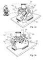
- Figs. 3a to 3c illustrate how the lower stabilizing platform 104 operates when the vessel on which the antenna system 100 is mounted is exposed to pitch and roll movements.
- the alignment of the vessel in relation to the horizontal plane 304 is represented by the alignment of the platform 102 in relation to the horizontal plane 104.
- the alignment of the connecting element 222 and the roll platform 214 corresponds to the alignment of the antenna orientation arrangement 108.
- Fig. 3a the vessel is rotated around the pitch axis 306, the change in inclination is detected by the inclinometer which transmits a control signal to the pitch actuator 210 so that the pitch platform 206 is rotated to a position where it is aligned with the horizontal plane 304.
- Fig. 3b illustrates a rotation of the vessel around the roll axis 308, the change in inclination is detected by the inclinometer which transmits a control signal to the roll actuator 218 so that the roll platform 214 is rotated to a position where it is aligned with the horizontal plane 304.
- the vessel is rotated around both the pitch axis 306 and the roll axis 308, the inclinometer detects the change in inclination and controls the pitch and roll actuators 210, 218 to align the roll platform with the horizontal plane 304.
- the first control circuitry (not shown) for acquiring pitch and roll parameters from the sensing device and for controlling the pitch and roll actuators based on the acquired parameters is typically arranged on the lower stabilizing platform 104 with a wired connection to the inclinometer 238 arranged on the upper directing platform 106.
- Fig. 4 illustrates the upper directing platform 106 comprising the antenna orientation arrangement 108.
- the antenna orientation arrangement 108 is maintained in alignment with the horizontal plane 304. Accordingly, the antenna orientation arrangement 108 controls the orientation of the antenna with respect to azimuth, elevation and polarization so that a desired signal from a selected satellite is received.
- the second control circuitry (not shown) for controlling the azimuth, elevation and polarization actuators, 226, 232 and 236, typically receive instructions from one or more systems onboard the vessel.
- the second control circuitry may receive positioning information from a global positioning system (GPS), heading information from a gyroscope and satellite position information based information stored on a server.
- GPS global positioning system
- the second control circuitry may also control the actuators based on a quality of the signal received by the antenna 110. Such a quality may for example be bit error rate (BER) or signal density.
- BER bit error rate
- Fig. 5 schematically illustrates the damping arrangement 500 according to an embodiment of the invention.
- the damping arrangement 500 is here represented by two stages connected in series, where the lower stage 502 comprise a damper 504 connected in parallel with a spring 506 and the upper stage 508 comprise a damper 510 connected in parallel with a spring 512 and an actuator 514.
- the damper represents a damping function where kinetic energy is converted to heat while the spring represents the function of energy storage for kinetic energy.
- the lower stage 502 corresponds to the wire-rope dampers 202 which have the function of both springs and dampers.
- the actuator 514 corresponds to the pitch and roll actuators 210, 218 which act as active damping elements in the damping arrangement.
- the spring 512 and damper 510 correspond to the axial dampers of the pitch and roll axles.
- the lower stage 502 i.e. the wire-rope dampers
- the wire-rope dampers also function as shock-absorbers.
- the upper stage 508, i.e. the axial dampers and the pitch and roll actuators, is configured to reduce vibrations between 0Hz and 5Hz.
- the person skilled in the art readily realizes that the disclosed example is merely one way in which a damping arrangement according to Fig. 5 may be achieved. Many alternative configurations and combinations of damping elements are possible for achieving the desired damping effect.
- the sensing device 238 may also be used to detect vibrations and to provide vibration parameters to the first control circuitry for controlling the pitch and roll actuators 210,218. Alternatively a separate sensing device may be used to detect vibrations.
- the damping parameters of the damping system are typically set in relation to the mass to be damped, the center of gravity and the eigenfrequencies of the system. With the suggested damping arrangement, at least the lower eigenfrequencies of the system can be damped and general vibration noise is reduced.
Landscapes
- Engineering & Computer Science (AREA)
- General Engineering & Computer Science (AREA)
- Mechanical Engineering (AREA)
- Variable-Direction Aerials And Aerial Arrays (AREA)
- Details Of Aerials (AREA)
Priority Applications (1)
| Application Number | Priority Date | Filing Date | Title |
|---|---|---|---|
| EP12163860.5A EP2650962A1 (fr) | 2012-04-12 | 2012-04-12 | Système de support d'antenne |
Applications Claiming Priority (1)
| Application Number | Priority Date | Filing Date | Title |
|---|---|---|---|
| EP12163860.5A EP2650962A1 (fr) | 2012-04-12 | 2012-04-12 | Système de support d'antenne |
Publications (1)
| Publication Number | Publication Date |
|---|---|
| EP2650962A1 true EP2650962A1 (fr) | 2013-10-16 |
Family
ID=46027637
Family Applications (1)
| Application Number | Title | Priority Date | Filing Date |
|---|---|---|---|
| EP12163860.5A Withdrawn EP2650962A1 (fr) | 2012-04-12 | 2012-04-12 | Système de support d'antenne |
Country Status (1)
| Country | Link |
|---|---|
| EP (1) | EP2650962A1 (fr) |
Cited By (18)
| Publication number | Priority date | Publication date | Assignee | Title |
|---|---|---|---|---|
| CN104793623A (zh) * | 2015-04-09 | 2015-07-22 | 深圳市宏腾通电子有限公司 | 一种简易寻星装置 |
| CN104807475A (zh) * | 2015-04-14 | 2015-07-29 | 深圳市宏腾通电子有限公司 | 动中通卫星天线倾角校准过程中零点漂移值的测量方法 |
| CN105173024A (zh) * | 2015-09-26 | 2015-12-23 | 哈尔滨工程大学 | 三自由度液压驱动重载稳定平台 |
| CN106797067A (zh) * | 2014-05-25 | 2017-05-31 | 萨迪斯飞以色列有限公司 | 整体双万向节设备 |
| CN107579769A (zh) * | 2017-10-19 | 2018-01-12 | 广州联星科技有限公司 | 收发一体机及卫星通信终端装置 |
| CN109250039A (zh) * | 2018-07-13 | 2019-01-22 | 哈尔滨工程大学 | 一种主动式回转运动补偿装置 |
| CN109270300A (zh) * | 2017-07-18 | 2019-01-25 | 中国航空工业集团公司济南特种结构研究所 | 一种天线罩测试转台 |
| US10283837B2 (en) | 2015-10-23 | 2019-05-07 | Viasat, Inc. | Apparatuses for mounting an antenna assembly |
| CN112379628A (zh) * | 2020-11-25 | 2021-02-19 | 新万基卫星技术有限公司 | 一种船载动中通用伺服控制系统 |
| CN112555617A (zh) * | 2020-12-23 | 2021-03-26 | 重庆华渝电气集团有限公司 | 一种大载荷三维稳定平台 |
| DE102020109341B3 (de) * | 2020-04-03 | 2021-07-01 | FoMa Systems GmbH | Stabilisierungsvorrichtung und Verfahren zur Stabilisierung eines Befestigungsbauteils |
| CN113685684A (zh) * | 2021-08-02 | 2021-11-23 | 南京晨光集团有限责任公司 | 一种手动自锁式方位和俯仰调整装置 |
| CN113985151A (zh) * | 2021-10-26 | 2022-01-28 | 九江精密测试技术研究所 | 一种多功能重载三轴天线测试转台 |
| CN114198455A (zh) * | 2021-12-15 | 2022-03-18 | 上海新纪元机器人有限公司 | 安装于运载设备的自平衡减振系统 |
| CN114204244A (zh) * | 2021-11-17 | 2022-03-18 | 北京无线电计量测试研究所 | 一种波束赋形天线测量装置 |
| WO2022087992A1 (fr) * | 2020-10-29 | 2022-05-05 | 深圳市大疆创新科技有限公司 | Ensemble antenne, dispositif mobile, et procédé de commande et support de stockage de dispositif mobile |
| CN116123422A (zh) * | 2022-09-08 | 2023-05-16 | 中国人民解放军国防科技大学 | 一种自稳定减震云台 |
| CN119153950A (zh) * | 2024-11-11 | 2024-12-17 | 深圳市天威讯无线技术有限公司 | 一种高增益定向的ser天线 |
Citations (3)
| Publication number | Priority date | Publication date | Assignee | Title |
|---|---|---|---|---|
| DE4405644A1 (de) * | 1994-02-22 | 1994-10-06 | Rst Raumfahrt Systemtechnik Gm | Verfahren und Vorrichtung zur Ausrichtung und Stabilisierung von Antennen für Satellitendatenempfang |
| US5922039A (en) * | 1996-09-19 | 1999-07-13 | Astral, Inc. | Actively stabilized platform system |
| WO2010075109A1 (fr) * | 2008-12-15 | 2010-07-01 | Sea Tel, Inc. | Socle pour antenne de poursuite |
-
2012
- 2012-04-12 EP EP12163860.5A patent/EP2650962A1/fr not_active Withdrawn
Patent Citations (3)
| Publication number | Priority date | Publication date | Assignee | Title |
|---|---|---|---|---|
| DE4405644A1 (de) * | 1994-02-22 | 1994-10-06 | Rst Raumfahrt Systemtechnik Gm | Verfahren und Vorrichtung zur Ausrichtung und Stabilisierung von Antennen für Satellitendatenempfang |
| US5922039A (en) * | 1996-09-19 | 1999-07-13 | Astral, Inc. | Actively stabilized platform system |
| WO2010075109A1 (fr) * | 2008-12-15 | 2010-07-01 | Sea Tel, Inc. | Socle pour antenne de poursuite |
Cited By (26)
| Publication number | Priority date | Publication date | Assignee | Title |
|---|---|---|---|---|
| US10197215B2 (en) | 2014-05-25 | 2019-02-05 | Satixfy Israel Ltd. | Integral dual gimbal device |
| CN106797067A (zh) * | 2014-05-25 | 2017-05-31 | 萨迪斯飞以色列有限公司 | 整体双万向节设备 |
| CN106797067B (zh) * | 2014-05-25 | 2019-11-05 | 萨迪斯飞以色列有限公司 | 整体双万向节设备 |
| CN104793623A (zh) * | 2015-04-09 | 2015-07-22 | 深圳市宏腾通电子有限公司 | 一种简易寻星装置 |
| WO2016165295A1 (fr) * | 2015-04-14 | 2016-10-20 | 深圳市宏腾通电子有限公司 | Procédé de mesure de la valeur de dérive du zéro pendant un processus d'étalonnage de l'angle d'inclinaison d'une antenne satellitaire dans un système de communication par satellite en cours de déplacement |
| CN104807475A (zh) * | 2015-04-14 | 2015-07-29 | 深圳市宏腾通电子有限公司 | 动中通卫星天线倾角校准过程中零点漂移值的测量方法 |
| CN105173024A (zh) * | 2015-09-26 | 2015-12-23 | 哈尔滨工程大学 | 三自由度液压驱动重载稳定平台 |
| US12230863B2 (en) | 2015-10-23 | 2025-02-18 | Viasat, Inc. | Apparatuses for mounting an antenna assembly |
| US11121448B2 (en) | 2015-10-23 | 2021-09-14 | Viasat, Inc. | Apparatuses for mounting an antenna assembly |
| US10283837B2 (en) | 2015-10-23 | 2019-05-07 | Viasat, Inc. | Apparatuses for mounting an antenna assembly |
| CN109270300A (zh) * | 2017-07-18 | 2019-01-25 | 中国航空工业集团公司济南特种结构研究所 | 一种天线罩测试转台 |
| CN107579769A (zh) * | 2017-10-19 | 2018-01-12 | 广州联星科技有限公司 | 收发一体机及卫星通信终端装置 |
| CN107579769B (zh) * | 2017-10-19 | 2024-04-12 | 广州联星科技有限公司 | 收发一体机及卫星通信终端装置 |
| CN109250039A (zh) * | 2018-07-13 | 2019-01-22 | 哈尔滨工程大学 | 一种主动式回转运动补偿装置 |
| DE102020109341B3 (de) * | 2020-04-03 | 2021-07-01 | FoMa Systems GmbH | Stabilisierungsvorrichtung und Verfahren zur Stabilisierung eines Befestigungsbauteils |
| US11519550B2 (en) | 2020-04-03 | 2022-12-06 | FoMa Systems GmbH | Stabilization device and method for stabilizing an attachment component |
| WO2022087992A1 (fr) * | 2020-10-29 | 2022-05-05 | 深圳市大疆创新科技有限公司 | Ensemble antenne, dispositif mobile, et procédé de commande et support de stockage de dispositif mobile |
| CN112379628A (zh) * | 2020-11-25 | 2021-02-19 | 新万基卫星技术有限公司 | 一种船载动中通用伺服控制系统 |
| CN112555617A (zh) * | 2020-12-23 | 2021-03-26 | 重庆华渝电气集团有限公司 | 一种大载荷三维稳定平台 |
| CN113685684A (zh) * | 2021-08-02 | 2021-11-23 | 南京晨光集团有限责任公司 | 一种手动自锁式方位和俯仰调整装置 |
| CN113985151A (zh) * | 2021-10-26 | 2022-01-28 | 九江精密测试技术研究所 | 一种多功能重载三轴天线测试转台 |
| CN113985151B (zh) * | 2021-10-26 | 2024-05-31 | 九江精密测试技术研究所 | 一种多功能重载三轴天线测试转台 |
| CN114204244A (zh) * | 2021-11-17 | 2022-03-18 | 北京无线电计量测试研究所 | 一种波束赋形天线测量装置 |
| CN114198455A (zh) * | 2021-12-15 | 2022-03-18 | 上海新纪元机器人有限公司 | 安装于运载设备的自平衡减振系统 |
| CN116123422A (zh) * | 2022-09-08 | 2023-05-16 | 中国人民解放军国防科技大学 | 一种自稳定减震云台 |
| CN119153950A (zh) * | 2024-11-11 | 2024-12-17 | 深圳市天威讯无线技术有限公司 | 一种高增益定向的ser天线 |
Similar Documents
| Publication | Publication Date | Title |
|---|---|---|
| EP2650962A1 (fr) | Système de support d'antenne | |
| CN108119731B (zh) | 姿态可调的全向隔振平台 | |
| US5897223A (en) | Stabilized platform system for camera | |
| JP6502283B2 (ja) | マイクロ慣性測定装置 | |
| ES2734393T3 (es) | Sistema de estabilización de plataforma | |
| US11209118B2 (en) | Support and stabilization systems | |
| KR100733961B1 (ko) | 페데스탈 장치 및 이를 구비한 위성추적 안테나 | |
| NO840395L (no) | Stabilisert plattform | |
| JP2009248853A (ja) | ヘリコプター用防振懸架装置 | |
| US10714807B2 (en) | Stabilization arrangement for stabilization of an antenna mast | |
| WO2014141708A1 (fr) | Dispositif d'antenne et procédé de commande d'un dispositif d'antenne | |
| WO2021134584A1 (fr) | Module de capteur de mouvement et plate-forme mobile | |
| JP2008228045A (ja) | 衛星追尾用アンテナ装置 | |
| WO2022176967A1 (fr) | Mécanisme rotatif, véhicule volant, et dispositif et procédé de commande de l'attitude d'une charge | |
| EP2752938B1 (fr) | Dispositif d'antenne | |
| JP2022125967A (ja) | 回転機構、飛行体、積載物の姿勢制御装置、方法 | |
| US9891341B2 (en) | Gravity gradiometer system with spherical air bearing based platform | |
| JP6349870B2 (ja) | レーダアンテナ装置 | |
| JP6361229B2 (ja) | レーダ装置及びその制御方法 | |
| JP2004136439A (ja) | 揺動部把持機構 | |
| CN114412962B (zh) | 球形自稳定姿态调整平台及方法 | |
| US2213832A (en) | Antivibration mount for direction indicating instruments | |
| JP4087355B2 (ja) | 追尾機器 | |
| WO2019129887A1 (fr) | Procédé de configuration d'un système d'isolation contre les vibrations d'une unité de mesure inertielle | |
| US3490728A (en) | Resilient supporting device |
Legal Events
| Date | Code | Title | Description |
|---|---|---|---|
| PUAI | Public reference made under article 153(3) epc to a published international application that has entered the european phase |
Free format text: ORIGINAL CODE: 0009012 |
|
| AK | Designated contracting states |
Kind code of ref document: A1 Designated state(s): AL AT BE BG CH CY CZ DE DK EE ES FI FR GB GR HR HU IE IS IT LI LT LU LV MC MK MT NL NO PL PT RO RS SE SI SK SM TR |
|
| AX | Request for extension of the european patent |
Extension state: BA ME |
|
| STAA | Information on the status of an ep patent application or granted ep patent |
Free format text: STATUS: THE APPLICATION IS DEEMED TO BE WITHDRAWN |
|
| 18D | Application deemed to be withdrawn |
Effective date: 20140417 |