EP2651081A1 - Computersystem, steuerung dafür und netzwerküberwachungsverfahren - Google Patents
Computersystem, steuerung dafür und netzwerküberwachungsverfahren Download PDFInfo
- Publication number
- EP2651081A1 EP2651081A1 EP11847623.3A EP11847623A EP2651081A1 EP 2651081 A1 EP2651081 A1 EP 2651081A1 EP 11847623 A EP11847623 A EP 11847623A EP 2651081 A1 EP2651081 A1 EP 2651081A1
- Authority
- EP
- European Patent Office
- Prior art keywords
- address
- transmission source
- controller
- received packet
- packet
- Prior art date
- Legal status (The legal status is an assumption and is not a legal conclusion. Google has not performed a legal analysis and makes no representation as to the accuracy of the status listed.)
- Withdrawn
Links
Images










Classifications
-
- H—ELECTRICITY
- H04—ELECTRIC COMMUNICATION TECHNIQUE
- H04L—TRANSMISSION OF DIGITAL INFORMATION, e.g. TELEGRAPHIC COMMUNICATION
- H04L63/00—Network architectures or network communication protocols for network security
- H04L63/14—Network architectures or network communication protocols for network security for detecting or protecting against malicious traffic
- H04L63/1441—Countermeasures against malicious traffic
- H04L63/1466—Active attacks involving interception, injection, modification, spoofing of data unit addresses, e.g. hijacking, packet injection or TCP sequence number attacks
-
- G—PHYSICS
- G06—COMPUTING OR CALCULATING; COUNTING
- G06F—ELECTRIC DIGITAL DATA PROCESSING
- G06F21/00—Security arrangements for protecting computers, components thereof, programs or data against unauthorised activity
- G06F21/50—Monitoring users, programs or devices to maintain the integrity of platforms, e.g. of processors, firmware or operating systems
- G06F21/55—Detecting local intrusion or implementing counter-measures
-
- H—ELECTRICITY
- H04—ELECTRIC COMMUNICATION TECHNIQUE
- H04L—TRANSMISSION OF DIGITAL INFORMATION, e.g. TELEGRAPHIC COMMUNICATION
- H04L12/00—Data switching networks
- H04L12/28—Data switching networks characterised by path configuration, e.g. LAN [Local Area Networks] or WAN [Wide Area Networks]
- H04L12/44—Star or tree networks
-
- H—ELECTRICITY
- H04—ELECTRIC COMMUNICATION TECHNIQUE
- H04L—TRANSMISSION OF DIGITAL INFORMATION, e.g. TELEGRAPHIC COMMUNICATION
- H04L12/00—Data switching networks
- H04L12/64—Hybrid switching systems
- H04L12/6418—Hybrid transport
-
- H—ELECTRICITY
- H04—ELECTRIC COMMUNICATION TECHNIQUE
- H04L—TRANSMISSION OF DIGITAL INFORMATION, e.g. TELEGRAPHIC COMMUNICATION
- H04L49/00—Packet switching elements
- H04L49/35—Switches specially adapted for specific applications
-
- H—ELECTRICITY
- H04—ELECTRIC COMMUNICATION TECHNIQUE
- H04L—TRANSMISSION OF DIGITAL INFORMATION, e.g. TELEGRAPHIC COMMUNICATION
- H04L49/00—Packet switching elements
- H04L49/70—Virtual switches
-
- H—ELECTRICITY
- H04—ELECTRIC COMMUNICATION TECHNIQUE
- H04L—TRANSMISSION OF DIGITAL INFORMATION, e.g. TELEGRAPHIC COMMUNICATION
- H04L63/00—Network architectures or network communication protocols for network security
- H04L63/10—Network architectures or network communication protocols for network security for controlling access to devices or network resources
- H04L63/102—Entity profiles
Definitions
- the present invention relates to a computer system, a controller, a monitoring method and a network monitoring program, and more particularly relates to a computer system using an openflow technique, and a network monitoring method for blocking an address spoofed packet.
- a MAC (Media Access Control) address is used in order to uniquely identify network devices (including computers and virtual machines) configuring a network.
- the MAC address can be easily spoofed.
- Gratuitous ARP Address Resolution Protocol
- the Gratuitous ARP is an ARP request packet in which its' own IP (Internet Protocol) address is set to a target IP address and provides two effects. One lies in the effect of finding out whether or not a something except itself uses the same IP address.
- the IP address can be judged to be duplicative.
- the other effect lies in a fact that a switch configuring the layer 2 network updates its own ARP table and MAC table with reference to a transmission source MAC address of the Gratuitous ARP packet, and consequently can follow the transfer of the computer and/or virtual computer to change the transfer route of the packet.
- a trouble can be induced in the network. For example, when the Gratuitous ARP packet in which the transmission source MAC address or target IP address is spoofed is transmitted by an illegal third party, the ARP table or MAC table of the switch configuring the layer 2 network is rewritten. Consequently, a TCP/IP communication of a legal user is easily interrupted. Moreover, a packet to be sent to the legal user can be intercepted because the packet is changed to be sent to an illegal person.
- a technique for monitoring and preventing illegal access and interruption using the foregoing ARP packet is described in, for example, JP 2005-210451A (refer to a patent literature 1).
- a system described in the patent literature 1 includes a monitoring host for monitoring an ARP request packet, and a database in which an IP address and physical address of a legal host inside a network are registered in advance.
- Themonitoring host when detecting an ARP request packet for the IP address or physical address that is not registered in the database, transmits the ARP request packet whose request source is the above monitoring host itself, to a request destination node of the ARP packet, and updates the ARP table of the node. Consequently, a reply packet to the illegal access is transferred to a monitor server without being sent to the illegal third party.
- the system described in the patent literature 1 can prevent the illegal access to the network, because the monitor server that detects the illegal ARP packet controls the transfer destination of the packet in the node.
- a technique in which transfer operations and the like in respective switches are unitarily controlled by an external controller in a computer network is proposed by the OpenFlow Consortium (refer to a non-patent literature 2).
- a network switch hereinafter, referred to as an openflow switch (OFS)
- OFS openflow switch
- the flow table of the OFS inside the network is unitarily set and managed by an openflow controller (OFC).
- the computer system based on the technique related to the present invention includes: an openflow controller 100 (hereinafter, referred to as an OFC 100); a switch group 200 including a plurality of open switches 102-1 to 102-n (hereinafter, referred to as OFS 102-1 to 102-n); and a host group 300 including a plurality of host computers 103-1 to 103-i (hereinafter, referred to as hosts 103-1 to 103-i).
- an openflow controller 100 hereinafter, referred to as an OFC 100
- a switch group 200 including a plurality of open switches 102-1 to 102-n hereinafter, referred to as OFS 102-1 to 102-n
- a host group 300 including a plurality of host computers 103-1 to 103-i (hereinafter, referred to as hosts 103-1 to 103-i).
- hosts 103-1 to 103-i each of n and i is a natural number of 2 or more.
- the OFSs 102-1 to 102-n are not distinguished from each other, they are collectively referred to as an OFS 102.
- the hosts 103-1 to 103-i are not distinguished from each other, they are collectively referred to as a host 103.
- the OFC 100 sets a communication route between the hosts 103 and sets a transfer operation (relay operation) to the OFS 102 on the route and the like. At this time, the OFC 100 sets a flow entry in which a rule for specifying a flow (packet data) and an action for defining an operation for the flow are correlated, in a flow table held by the OFS 102.
- the OFS 102 on the communication route determines a transfer destination of received packet data and carries out a transfer process, in accordance with the flow entry set by the OFC 100. Consequently, the host 103 can transmit and receive the packet data to and from the different host 103 by using the communication route set by the OFC 100. That is, in the computer system that uses the openflow, the OFC 100 for setting the communication route and the OFS 102 for carrying out the transfer process are separated, which enables the communication in the entire system to be unitarily controlled and managed.
- the OFS 102-1 refers to transmission destination information (header information: for example, a destination MAC address and a destination IP access) in the packet received from the host 103-1 and searches an entry, which coincides with the header information, from the flow table held inside the OFS 102-1.
- the content of the entry set in the flow table is defined in, for example, a non-patent literature 2.
- the OFS 102-1 transfers the packet data (hereinafter, referred to as a first packet) or the header information of the first packet to the OFC 100.
- the OFC 100 which receives the first packet from the OFS 102-1, determines a route 400 on the basis of the information, such as a transmission source host and a transmission destination host, which is included in the packet.
- the OFC 100 instructs all of the OFS 102 on the route 400 to set a flow entry for defining the transfer destination of the packet (issue a flow table update instruction).
- the OFS 102 on the route 400 updates the flow table managed by itself, on the basis of the flow table update instruction. After that, the OFS 102 starts transferring the packet, in accordance with the updated flow table. Consequently, through the route 400 determined by the OFC 100, the packet arrives at the host 103-i of the destination.
- an object of the present invention is to be able to monitor illegal access to a network in an openflow protocol environment.
- Another object of the present invention is to block communication interruption to a network in an openflow protocol environment.
- Another object of the present invention is to improve security intensity against illegal access and interruption using spoofed address.
- a computer system includes: a controller; a switch configured to perform, on a received packet complying with a flow entry set by the controller, a relay operation regulated by the flow entry; and a host terminal configured to be connected to the switch.
- the switch notifies the controller of transmission source address information of a received packet which does not comply with a flow entry set to itself.
- the controller judges, when address information of a legal host terminal does not coincide with the transmission source address information, that a transmission source address of the received packet is spoofed.
- a controller includes: a flow controlling section; and an address spoofing detecting section.
- the flow controlling section sets a flow entry to a switch.
- the switch performs, on a received packet complying with a set flow entry, a relay operation regulated by the flow entry, and notifies the flow controlling section of transmission source address information of a received packet which does not comply with the flow entry set to itself.
- the address spoofing detecting section judges, when the transmission source address information notified to the flow controlling section does not coincide with address information of a legal host terminal, that a transmission source address of the received packet is spoofed.
- a function of a controller according to the present invention is realized by a program stored in a storage device and executed by a computer.
- a network monitoring method is a network monitoring method executed by a computer system, which includes a switch configured to perform, on a received packet complying with a flow entry set by a controller, a relay operation regulated by the flow entry.
- the monitoring method includes: the switch notifying the controller of transmission source address information of a received packet not complying with a flow entry set to itself; and the controller judging, when address information of a legal host terminal does not coincide with the transmission source address information, that a transmission source address of the received packet is spoofed.
- monitoring of illegal access to a network in an openflow protocol environment can be achieved.
- blocking of communication interruption to a network in an openflow protocol environment can be achieved.
- the computer system according to the present invention establishes a communication route and carries out transfer control of packet data by using the openflow technique, similarly to the system shown in Fig. 1 .
- the computer system in the first exemplary embodiment monitors whether address spoofing of an ARP request packet or IP packet is present, on the basis of the first packet transmitted to an openflow controller 2 from an openflow virtual switch 33 which works on a virtual server 3.
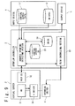
- Fig. 2 is a view showing a configuration of the computer system in the first exemplary embodiment according to the present invention. With reference to Fig. 2 , the configuration of the computer system in the first exemplary embodiment according to the present invention will be described.
- the computer system in the first exemplary embodiment includes an input device 1, an openflow controller 2 (hereinafter, referred to as an OFC 2), a virtual server 3, an openflow switch (hereinafter, referred to as an OFS 4) and an output device 5.
- an openflow controller 2 hereinafter, referred to as an OFC 2
- a virtual server 3 an openflow switch (hereinafter, referred to as an OFS 4)
- an output device 5 an input device 1
- an openflow controller 2 hereinafter, referred to as an OFC 2
- a virtual server 3 an openflow switch
- an OFS openflow switch
- the input device 1 in the first exemplary embodiment includes a storage device which records virtual server data 11 and virtual machine data 12 (VM data 12), which are used to verify access spoofing.
- the virtual server data 11 is the data required for the OFC 2 to access the virtual server 3.
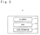
- Fig. 3 is a view showing one example of the structure of the virtual server data 11 used for the address spoofing verification in the first exemplary embodiment.
- the virtual server data 11 includes: an IP address 111 assigned to the legal virtual server 3 that is allowed to connect to the system; a DPID 112 (Data Path ID) of the openflowvirtual switch 33 to which a physical network interface of the virtual server 3 is connected; and login information 113 to access the virtual server 3.
- Each of the IP address 111, the DPID 112 and the login information 113 is correlated with each virtual server 3 and recorded as the virtual server data 11 in the input device 1.
- the DPID 112 is the number assigned to each of the OFS 4 and the openflow virtual switch 33 (hereinafter, referred to as OFVS 33) in order to uniquely identify the OFS 4 and the OFVS 33.
- the login information 113 includes ID and password information to access (log in) the virtual server 3.
- Fig. 4 is a view showing one example of the structure of the VM data 12 used for the address spoofing verification in the first exemplary embodiment.
- the VM data 12 is the information to specify a virtual machine 31 existing on the network that is managed by the openflow controller 2.
- the VM data 12 includes a VM name 120 for uniquely identifying the virtual machine 31 and interface information 121 for uniquely specifying the network interface possessed by the virtual machine 31.
- the VMname 120 and the interface information 121 are correlated with each virtual machine 31 and recorded as the VM data 12 in the input device 1.
- the VM name 120 for example, an UUID (Universal Unique Identifier) set to the virtual machine 31 is preferable.
- the interface information 121 includes a MAC address 122 and an IP address 123, which are assigned to the physical network interface of the virtual machine 31.
- the virtual server data 11 and the VM data 12 that are recorded in the input device 1 may be set or updated in advance by a user or may be set or updated on the basis of data obtained by the OFC 2.
- the OFC 2 controls establishment of a communication route for a packet transfer and a packet transfer process in the system, on the basis of the openflow technique.
- the openflow technique indicates the technique for setting a multilayer and route information for each flow to the OFS 4 and OFVS 33 on the communication route and carrying out a route control and a node control (for the detailed information, refer to the non-patent literature 1) according to the rooting policy (flowentry : flow + action). Consequently, a route control function is separated from a router and a switch. Thus, the optimal routing and traffic management can be carried out by the centralized control of a controller.
- the OFS 4 and OFVS 33 to which the openflow technique is applied treat the communication as the flow of END2END and not as the flow for each packet or frame such as the conventional router and switch.
- the OFC 2 is preferred to be attained by a computer that includes a CPU and a storage device.
- the CPU since the CPU (that is not shown) executes a program stored in the storage device, respective functions of an address spoofing detecting section 21 and a flow controlling section 22 are attained as shown in Fig. 2 .
- the address spoofing detecting section 21 converts each of the virtual server data 11 and the VM data 12, which are supplied by the input device 1, into a format that can be easily retrieved, and records as a virtual server database 23 and a VM database 24, in an address spoofing verification database 20.
- the flow controlling section 22 sets or deletes a flow entry (rule + action) to or from the switch (here, the OFS 4 or OFVS 33) based on the open flow protocol. Consequently, the OFS 4 or the OFVS 33 executes an action (for example, relaying or discarding of packet data) corresponding to a rule based on header information of a received packet.
- the rule set to the flow entry defines, for example, combinations of addresses and identifiers from a layer 1 to a layer 4 in an OSI (Open Systems Interconnection) reference model, which are included in header information in packet data of TCP/IP.
- OSI Open Systems Interconnection
- the respective combinations of a physical port of the layer 1, a MAC address of the layer 2, an IP address of the layer 3, a port number of the layer 4, and a VLAN tag (VLAN id) are set as the rule.
- a priority order (VLAN Priority) may be assigned to the VLAN tag.
- the addresses and the identifiers like the port number and so on set as the rule by the flow controlling section 22 may be set within a predetermined range.
- a destination address, a transmission source address and the like are preferred to be distinguished and set as the rule.
- the range of a MAC destination address, the range of a destination port number to specify an application of a connection destination, and the range of a transmission source port number to specify an application of a connection source are set as the rule.
- the identifier to specify a data transfer protocol may be set as the rule.
- a method of treating packet data of TCP/IP is defined. For example, information to indicate whether or not received packet data is relayed, and its transmission destination if the received packet data is relayed are set. Also, as the action, information gives instructions of copying or discarding of packet data may be set.
- the flow controlling section 22 when receiving notification of the first packet from the OFS 4 or OFVS 33, inquires of the address spoofing detecting section 21 whether the packet transfer is allowable and sets the flow entry or discards the first packet, in accordance with the inquiry result.
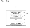
- the flow controlling section 22 obtains verification information 6 shown in Fig. 5A or 5B , via the notification of the first packet (hereinafter, referred to as PacketIN) from the OFS 4 or OFVS 33.
- the verification information 6 includes transmission source address information 60 of the first packet, an identifier of a notification source switch (for example, a DPID 63), and a port name of the notification source switch (a reception port number 64).
- the transmission source address information 60 includes a transmission source MAC address 61 and a target IP address 62.
- the transmission source address information 60 includes the transmission source MAC address 61 and a transmission source IP address 65.
- the flow controlling section 22 transmits the verification information 6 to the address spoofing detecting section 21 and inquires whether the packet transfer is allowable. As the result of this inquiry, if the packet transfer is judged to be allowable, the flow controlling section 22 determines a communication route from the header information of the first packet. Then, the flow controlling section 22 sets a flow entry, which is used for transferring a packet coincident with the header information to the communication route, to the OFS 4 and OFVS 33 on the communication route. On the other hand, if the packet transfer is judged to be disallowable in the address spoofing detecting section 21, the first packet of the inquiry target is discarded. At this time, the flow controlling section 22 is preferred to set a flow entry, which is used for discarding a packet coincident with the header information of the first packet, to the notification source switch of the first packet.
- the flow controlling section 22 analyzes the first packet notified by the OFS 4 or OFVS 33. Then, only if the packet is the ARP packet, the flow controlling section 22 executes the above inquiring of the address spoofing detecting section 21, and the inquiring about the PacketIN other than the ARP packet may be omitted. In this case, the OFC 2 monitors only the ARP. However, the number of the inquiries made to the address spoofing detecting section 21 and the load on the address spoofing detecting process are reduced.
- the address spoofing detecting section 21 uses the verification information 6 transmitted by the flow controlling section 22 and the information recorded in the verifying database 20 and carries out the address spoofing versification.
- the address spoofing detecting section 21 obtains the verification information 6 together with an asynchronously-generated event from the flow controlling section 22.
- the address spoofing detecting section 21 uses the received transmission source address information 60 (the combination of the MAC address and the IP address) as a retrieval key, retrieves the VM database 24 and then obtains the VM name 120 (UUID of the virtual machine 31) corresponding to the interface information 121 coincident with the retrieval key (MAC Address ⁇ IP Address Verification). Consequently, the address spoofing detecting section 21 specifies the virtual machine 31 corresponding to the received transmission source address information 60.
- the address spoofing detecting section 21 cannot specify the virtual machine 31 corresponding to the received transmission source address information 60 as the result of the retrieval of the VM database 24, namely, if the interface information (the MAC address 122 and the IP address 123) coincident with the combination of the transmission source MAC address 61 and the target IP address 62 (the transmission source IP address 65) does not exist in the VM database 24, the address is judged to be spoofed.
- the address spoofing detecting section 21, which judges that the address is spoofed, instructs the flow controlling section 22 to discard the packet coincident with the header information of the first packet, which is judged to be the address spoofing, without allowing the packet transfer.
- the address spoofing detecting section 21 uses the DPID 63 of the received notification source switch as a retrieval key, retrieves the virtual server database 23 and then obtains the IP address 111 and the login information 113 (for example, the password information) corresponding to the DPID 112 coincident with the retrieval key. Consequently, the address spoofing detecting section 21 can specify a host OS 32 corresponding to the received DPID 63 and also obtain information to access (log in) the host OS 32.
- the address spoofing detecting section 21 accesses the host OS 32 in the virtual server 3 by using the IP address 111 and the login information 113, which are obtained from the virtual server database 23, and then obtains the information (hereinafter, referred to as transmission source information 7) with regard to the virtual machine 31, which coincides with the VM name 120 obtained from the VM database 24.
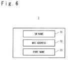
- the address spoofing detecting section 21 obtains the transmission source information 7 shown in Fig. 6 .
- the transmission source information 7 includes: a list of a VM name 71 (for example, UUID) to identify the virtual machine 31 specified by the address spoofing detecting section 21; a MAC address 72 of an interface used by the virtual machine 31; and a list of a port name 73 (port number) of the OFVS 33 to which the interface is connected.
- a VM name 71 for example, UUID
- MAC address 72 of an interface used by the virtual machine 31
- port name 73 port number
- the address spoofing detecting section 21 verifies whether a MAC address coincident with the transmission source MAC address 61 received from the flow controlling section 22 exists in the MAC address 72 of the virtual machine 31 that is obtained from the virtual server 3 (MAC Address Verification).
- the address spoofing detecting section 21 determines whether transfer of the packet coincident with the header information of the notified first packet is allowable, on the basis of the result of the MAC address verification, and instructs the flow controlling section 22. For example, if the MAC address coincident with the transmission source MAC address 61 is not included in the transmission source information 7, the address spoofing detecting section 21 judges the notified first packet as the illegal access whose address is spoofed.
- the address spoofing detecting section 21 does not allow transfer of a packet coincident with the header information of the first packet and instructs to discard the packet.
- the address spoofing detecting section 21 judges that there is no address spoofing and instructs the flow controlling section 22 to set a flow entry for transferring a packet coincident with the header information of the notified first packet.
- the address spoofing detecting section 21 judges that the address is spoofed.
- the address spoofing detecting section 21 does not allow transfer of a packet coincident with the header information of the first packet that is judged to be the address spoofing, and instructs the flow controlling section 22 to discard the packet.
- the output device 5 is exemplified as a monitor or a printer and visibly outputs information (for example, a VM name, MAC address or IP address of a VM which performs spoofing) to specify a virtual machine that spoofs a MAC address or IP address. Also, when the address spoofing detecting section 21 obtains the port name 73 of the virtual machine which performs spoofing, the output device 5 is preferred to visibly output the port name 73. Consequently, it is possible to specify which port of which switch the illegal packet with the spoofed IP address and/or MAC address has invaded from.
- information for example, a VM name, MAC address or IP address of a VM which performs spoofing
- the virtual server 3 is a computer apparatus (physical server) including a CPU and RAM which are not shown, and attains at least one virtual machine 31 and OFVS 33 by executing a program stored in a storage device that is not shown.
- the virtual machine 31 and the OFVS 33 are attained by, for example, a guest operation system ((GOS) that is not shown) which is emulated on the host operation system 32 (host OS 32) or software operating on the GOS.
- the virtual machine 31 is managed by a virtual machine monitor (VMM) operating on the host OS 32.
- VMM virtual machine monitor
- the virtual machine 31 functions as a host terminal, which carries out a communication with a different host terminal (for example, the virtual machine 31 in a different virtual server 3 or a network device that is not shown) through the OFVS 33.
- the OFVS 33 is operated in accordance with the openflow protocol and determines a processing method (action) of a packet received from the virtual machine 31, in accordance with a flow entry set (updated) by the OFC 2.
- action there are, for example, transferring the received packet to the OFS 4 and discarding the received packet.
- the OFVS 33 serves as a switch for firstly receiving a packet transmitted from the virtual machine 31. That is, the OFVS 33 corresponds to an entrance to this system, with regard to the virtual machine 31 serving as a host terminal.
- Fig. 2 only one virtual server 3 is provided in the system.
- the number of the virtual servers 3 is not limited to 1, and a plurality of virtual servers 3 is provided.
- a plurality of virtual machines 31 and OFVSs 33 may be provided in the virtual server 3.
- the plurality of virtual servers 3 (OFVSs 33) provided in the system are connected through the OFS 4 that is operated in accordance with the openflow protocol.
- the OFS 4 determines a processing method (action) of a received packet in accordance with a flow entry set (updated) by the OFC 2.
- action a processing method of a received packet in accordance with a flow entry set (updated) by the OFC 2.
- the action for the received packet there are, for example, transferring the received packet to the different OFS 4 or OFVS 33 and discarding the received packet.
- the setting of the flow entry for the OFVS 33 or OFS 4 is carried out in accordance with a Flow-mod request from the OFC 2 as mentioned above.
- the OFVS 33 or OFS 4 when receiving a packet having the header information that does not comply (or coincide) with the rule of the flow entry set to itself, notifies the OFC 2 of the packet as the first packet (PacketIN).
- the OFVS 33 or OFS 4 transmits an identifier (for example, DPID) for identifying the port number receiving the packet or itself, together with the first packet or the header information of the first packet, to the OFC 2. Consequently, the OFVS 33 or OFS 4 transmits the verification information 6 to the OFC 2.
- DPID identifier
- Fig. 7 is a sequence diagram showing one example of the network monitoring operation in the first exemplary embodiment.
- the network monitoring operation when a packet is transferred from the virtual machine 31 to the system will be described.
- the virtual server data 11 and the VM data 12 are recorded in advance from the input device 1 to the address spoofing verification database 20 in the OFC 2 (Steps S1 to S4).
- the virtual server data 11 given by the input device 1 is supplied to the address spoofing detecting section 21 and stored in the virtual server database 23 (Steps S1 and S2).
- the virtual server database 23 is updated on the basis of the newest virtual server data 11.
- the VM data 12 given by the VM data 12 is supplied to the address spoofing detecting section 21 and stored in the VM database 24 (Steps S3 and S4).
- the VM database 24 is updated on the basis of the newest VM data 12.
- the virtual server database 23 and the VM database 24 can be always retrieved by the address spoofing detecting section 21.
- the virtual server database 23 and the VM database 24 may be updated during an operation of the system. The updating order is not limited to the order shown in Fig. 7 .
- the network monitoring operation when a packet is transferred from the virtual machine 31 to the system is described.
- the virtual machine 31 transmits a Gratuitous ARP packet or an IP packet (Step S5).
- the packet from the virtual machine 31 is transferred through the OFVS 33 to outside the virtual server 3. That is, the OFVS 33 serves as the entrance to the network for the packet.
- the OFVS 33 judges whether header information of the Gratuitous ARP packet or IP packet received from a virtual port, to which the virtual machine 31 is connected, complies (coincides) with a rule of the flow entry set to itself. If there is a complying rule, the received packet is treated in accordance with the action corresponding to the rule (for example, transferring to the OFS 4 or discarding) (which is not shown). On the other hand, if (a rule in) the flow entry complying (coinciding) with the header information of the received packet is not set, the OFVS 33 notifies the flow controlling section 22 in the OFC 2 of the received packet as the first packet (Step S6).
- the virtual machine 31 when the virtual machine 31 is activated on the virtual server 3, or when the virtual machine 31 is moved onto the virtual server 3 from a different virtual server (that is not shown), a MAC address and IP address assigned to a physical network interface, to which the virtual machine 31 is connected, become new. For this reason, the Gratuitous ARP packet and IP packet firstly transmitted by the virtual machine 31 after the activation (movement) are judged as the first packet in the OFVS 33, and the PacketIN of the Gratuitous ARP packet and IP packet are done to the flow controlling section 22.
- the OFVS 33 transmits the first packet or the header information of the first packet together with the DPID 63 of the OFVS 33 to the flow controlling section 22.
- the flow controlling section 22 to which the PacketIN is done extracts the verification information 6 from the information transmitted from the OFVS 33 together with an asynchronous event and outputs to the address spoofing detecting section 21 (Step S7).
- the address spoofing detecting section 21 extracts the transmission source address information 60 from the verification information 6 received together with the asynchronous event and verifies the transmission source address of the first packet by using the VM database 24 (Step S8: MAC Address ⁇ IPAddress Verification) . Indetail, the address spoofing detecting section 21 verifies whether the interface information 121 (the MAC address 122 and the IP address 123) coincident with the transmission source address information 60 (the transmission source MAC address 61, the target IP address 62 or the transmission source IP address 65) exists in the VM database 24 (MAC Address • IP Address Verification).
- the address spoofing detecting section 21 judges that one or both of the MAC address and the IP address is spoofed, and instructs the flow controlling section 22 to discard the packet (Step S13).
- the address spoofing detecting section 21 obtains the VM name 120 (UUID) corresponding to the interface information 121.
- the address spoofing detecting section 21 uses the DPID 63 of the OFVS 33 received together with the asynchronous event as a retrieval key and retrieves the IP address 111 and the login information 113 from the virtual server database 23 (Step S9).
- the address spoofing detecting section 21 judges that one or both of the MAC address and the IP address is spoofed, and instructs the flow controlling section 22 to discard the packet (Step S13).
- the address spoofing detecting section 21 logs in the host OS 32 specified by the obtained IP address 111, by using the obtained login information 113. In succession, the address spoofing detecting section 21 obtains information of the virtual machine 31 corresponding to the VM name 120 (UUID) obtained at the step S8 as the transmission source information 7 (Step S10).
- the address spoofing detecting section 21 judges that one or both of the MAC address and the IP address of the first packet is spoofed and instructs the flow controlling section 22 to discard the packet (Step S13).
- the address spoofing detecting section 21 firstly retrieves whether the transmission source information 7 includes a MAC address coincident with the transmission source MAC address 61 of the first packet (Step S11: MAC Address Verification).
- Step S11 MAC Address Verification
- the address spoofing detecting section 21 judges that the MAC address of the first packet is spoofed and instructs the flow controlling section 22 to discard the packet (Step S13).
- Step S11 if there is the MAC address 72 coincident with the transmission source MAC address 61 in the transmission source information 7, the address spoofing detecting section 21 verifies whether the port name 73 correlated with the MAC address 72 coincides with the reception port number 64 of the first packet (Step S12: Reception port Verification).
- Step S12 Reception port Verification
- the address spoofing detecting section 21 judges that one or both of the MAC address and the IP address of the first packet is spoofed and instructs the flow controlling section 22 to discard the packet (Step S13).
- the address spoofing detecting section 21 judges that there is no address spoofing with regard to the first packet, and instructs the flow controlling section 22 to set a flow entry for transferring the packet (Step S13).
- the flow controlling section 22 which is instructed to discard the packet, discards the first packet of the PacketIN, and sets a flow entry, in which a part or all of the header information of the packet is used as a rule and packet discarding is used as an action, to the OFVS 33 (Step S14).
- the flow controlling section 22 sets the flow entry, in which the reception port number of the first packet and the transmission source MAC address are used as the rule and the discarding of the received packet coincident with the rule is used as the action, to the OFVS 33 of the notification source of the first packet. Consequently, after that, in the OFVS 33, when the packet judged as spoofing by the OFC 2 is received, it is discarded without any notification to the OFC 2, and the invasion to the network of the illegal packet can be blocked at the entrance of the network.
- the flow controlling section 22 which is instructed to transfer the packet, sets a flow entry, in which a part or all of the header information of the first packet of the PacketIN is used as a rule and packet transferring is used as an action, to the switch (the OFVS 33 or OFS 4) on the communication route (Step S14).
- the address spoofing detecting section 21 which judges that the address is spoofed at the steps S8, S9, S10 and S11, outputs the transmission source address information 60 received from the flow controlling section 22 together with the asynchronous event at the step S7 to the output device 5 (Step S15).
- the output device 5 visibly outputs the transmission source address information 60 (the transmission source MAC address 61 and the target IP address 62 or the transmission source IP address 65) as the spoofed address.
- the address spoofing detecting section 21, when judging that the address is spoofed, may output the reception port number 64 to the output device 5. In this case, the output device 5 visibly outputs the reception port number 64.
- Fig. 8 is a view showing the specific example to describe the configuration and operation of the computer system in the first exemplary embodiment.
- the virtual server database 23 registers, as the virtual server data 11, the IP address 111: "192.168.10.10", the DPID 112: “vSwitchA (DPID 01)", “vSwitchB (DPID 02)" and the login information 113: "Password-1".
- the VM database 24 registers, as the VM data 12, the VM name 120: "VM-B (UUID-B)" and the interface information 121: "IF-c:MAC-c, IP-c".
- the virtual server 3 includes: two virtual machines 31: "VM-A” and “VM-B”; and two OFVSs 33: "vSwitchA” and "vSwitchB".
- the virtual machine 31 "VM-A” has two interfaces "IF-a” and "IF-b", and the virtual machine 31 "VM-B” has one interface "IF-c”.
- the OFVS 33 "vSwitchA” is connected to a port "Port-A”
- the OFVS 33 "vSwitchB” is connected to two ports "Port-B” and "Port-C".
- the OFVS 33 "vSwitchB” receives the packet through the port "Part-C”.
- the OFVS 33 "vSwitchB” does the PacketIN of the received packet as the first packet to the flow controlling section 22.
- the flow controlling section 22 notifies the address spoofing detecting section 21 of the verification information 6 together with the asynchronous event in response to the PacketIN.
- the reception port number 64: "Port-C” are notified as the verification information 6.
- the address spoofing detecting section 21 carries out the MAC address ⁇ IP address verification by using the notified transmission source MAC address 61 "MAC-c" and target IP address 62 "IP-c".
- the address spoofing detecting section 21 extracts the VM name "VM-B (UUID-B)" corresponding to the interface information 121.
- the address spoofing detecting section 21 obtains the IP address 111: "192.168.10.10” and the login information 113: "Pasword-1", which correspond to the DPID 112 coincident with the DPID 63 "DPID 02" received by the PacketIN, inside the virtual server database 23, and accesses (logs in) the host OS 32 by using them. Consequently, the address spoofing detecting section 21 obtains information with regard to the virtual machine 31 of the VM name "VM-B (UUID-B)" extracted from the VM database 24, as the transmission source information 7, from the host OS 32 of the access destination.
- VM-B UUID-B
- the address spoofing detecting section 21 obtains the VM name 71: "VM-B (UUID-B)", the interface name: “IP-c”, the MAC address 72: “MAC-c”, and the port name 73: "Port-C”.
- the address spoofing detecting section 21 carries out the MAC address verification.
- the MAC address 72 "MAC-c” which coincides with the transmission source MAC address 61 "MAC-c" received by the PacketIN.
- the address spoofing detecting section 21 judges that there is no spoofed address in the reception port verification, because the port name "Port-C" corresponding to the MAC address 72 "MAC-c” coincides with the reception port number "Port-C" corresponding to the transmission source MAC address 61.
- the address spoofing detecting section 21 since judging that there is no spoofing as the result of all of the address spoofing verifications, judges that the Gratuitous ARP packet notified as the first packet uses the legal transmission source MAC address and target IP address, and then instructs the flow controlling section 22 to transfer the packet.
- the flow controlling section 22 sets, for example, a flow entry defining a rule of the transmission source MAC address: "MAC-c” and the target IP address: "IP-c” and an action of "transferring to the OFS 4", to the OFVS 33 "vSwitchA". Consequently, the OFVS 33 "vSwitchA", when receiving the ARP packet complying with the set rule, transfers the packet to the OFS 4.
- the flow controlling section 22 sets, for example, a flow entry defining a rule of the transmission source MAC address: "MAC-c" and the target IP address: "IP-c” and an action of "discarding of a packet" , to the OFVS 33 "vSwitchA", in response to the packet discarding instruction from the address spoofing detecting section 21. Consequently, the OFVS 33 "vSwitchA", when receiving the ARP packet complying with the set rule, discards the packet.
- the verification information 6 which is supplied together with the asynchronous event to the address spoofing detecting section 21 is visibly outputted by the output device 5.
- the system according to the present invention can detect: the Gratuitous ARP packet in which the transmission source MAC address or the target IP address is spoofed; and the IP packet in which the transmission source MAC address or the transmission source IP address is spoofed, and visibly output them. Also, it is possible to specify the MAC address and IP address of the transmission source of the detected address spoofing packet, on the basis of the verification information 6 obtained from the OFVS 33 by the PacketIN. Also, the DPID and reception port number of the OFVS 33 which does the PacketIN can be specified, which can specify the physical position from which the illegal access is tried.
- the system according to the present invention uses the openflow protocol.
- the switch (the OFVS 33 in the above example) which is the entrance when the address spoofing packet enters the layer 2 network
- the packet judged as the address spoofing can be discarded in the switch.
- the illegal ARP packet or IP packet invades the network this can be blocked.
- the system according to the present invention verifies the ARP packet or IP packet, which is transmitted by a disallowed outsider, on the basis of the combination of the transmission source MAC address, the transmission source IP address and the reception port of the switch, and carries out the control so that it does not invade the network. For this reason, according to the present invention, the disallowed outsider can be blocked from illegally using an unused IP address and accessing the network.
- the system according to the present invention can block an excessive traffic that spoofs the MAC address or IP address, especially, a broadcast traffic before it invades the layer 2 network.
- the excessive traffic in the network can be reduced.
- the first exemplary embodiment is described about the exemplary embodiment that includes the OFVS 33 which uses the openflow protocol.
- the present invention is not limited thereto. Even if the virtual switch does not use the openflow protocol, the present invention can be applied to a case inwhich a switch connectedbetween servers is operated in accordance with the openflow protocol.
- the computer system in the second exemplary embodiment monitors whether address spoofing of an ARP request packet or IP packet is present on the basis of the first packet that is transmitted to the openflow controller 2 from the openflow switch 4 for connecting a virtual server 3' and a different host terminal.
- configurations and operations that differ from those of the first exemplary embodiment will be described in detail, and descriptions of the similar configurations and operations are omitted.
- Fig. 9 is a view showing a configuration in the second exemplary embodiment of the computer system according to the present invention.
- the virtual server 3' in the second exemplary embodiment includes a virtual switch 34 of a layer 2 that is not based on the openflow protocol, instead of the openflow virtual switch 33 in the first exemplary embodiment.
- the PacketIN of the Gratuitous ARP packet transmitted from the virtual machine 31 is done to the flow controlling section 22 from the OFS 4. That is, the OFS 4 in the second exemplary embodiment corresponds to the entrance to this system with respect to the virtual machine 31 serving as the host terminal.
- the input device 1 in the second exemplary embodiment inputs a virtual server data 11' shown in Fig. 10 to the OFC 2.
- the configurations other than those configurations are similar to the first exemplary embodiment.
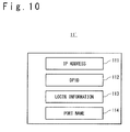
- Fig. 10 is a view showing one example of the structure of the virtual server data 11' that is used in the address spoofing verification in the second exemplary embodiment.
- the virtual server data 11' includes: an IP address 111 assigned to the virtual server 3', a DPID 112 of the OFS 4 to which a physical network interface of the virtual server 3' is connected, login information 113 to access the virtual server 3' and a port name 114 to which the OFS 4 is connected.
- Each of the IP address 111, the DPID 112, the login information 113 and the port name 114 is correlated with each virtual server 3' and recorded as the virtual server data 11' in the input device 1.
- Step S21 to S24 when the computer system is activated, the virtual server data 11' and the VM data 12 are recorded in advance from the input device 1 to the address spoofing verification database 20 in the OFC 2 (Steps S21 to S24). Detailed operations are similar to those of the steps S1 to S4 shown in Fig. 7 .
- the network monitoring operation when a packet is transferred from the virtual machine 31 to the system is described.
- the virtual machine 31 transmits a Gratuitous ARP packet or an IP packet (Step S25).
- the packet from the virtual machine 31 is transferred through the virtual switch 34 to the OFS 4 outside the virtual server 3'.
- the OFS 4 judges whether header information of the Gratuitous ARP packet or IP packet received from a port connected to the virtual server 3' complies (coincides) with a rule of the flow entry set for itself. If there is a complying rule, the received packet is treated in accordance with the action corresponding to the rule (for example, transferring to the different OFS 4 or discarding) (which is not shown). On the other hand, if (a rule in) the flow entry complying (coinciding) with the header information of the received packet is not set, the OFS 4 notifies the flow controlling section 22 in the OFC 2 of the received packet as the first packet (Step S26). Here, the OFS 4 transmits the first packet or the header information of the first packet together with the DPID 63 of the OFS 4 to the flow controlling section 22, on the basis of the PacketIN.
- the flow controlling section 22 to which the PacketIN is done extracts the verification information 6 from the information transmitted from the OFS 4 together with an asynchronous event and outputs to the address spoofing detecting section 21 (Step S27).
- the address spoofing detecting section 21 verifies, similarly to the step S8 shown in Fig. 7 , the transmission source address of the first packet by using the virtual server DB 23 and (Step S28: MAC Address ⁇ IP Address Verification).
- Step S28 MAC Address ⁇ IP Address Verification.
- the address spoofing detecting section 21 judges that one or both of the MAC address and the IP address of the first packet is spoofed, and instructs the flow controlling section 22 to discard the packet (Step S33).
- the address spoofing detecting section 21 obtains the VM name 120 (UUID) corresponding to the interface information 121.
- the address spoofing detecting section 21 uses the DPID 63 of the OFS 4 received together with the asynchronous event as a retrieval key and retrieves the IP address 111, the login information 113 and the port name 114 from the virtual server database 23 (Step S29).
- the address spoofing detecting section 21 judges that one or both of the MAC address and the IP address is spoofed, and instructs the flow controlling section 22 to discard the packet (Step S33).
- Step S29 if the IP address 111, the login information 113 and the port name 114 corresponding to the DPID 63 are obtained, the address spoofing detecting section 21 compares the port name 114 obtained from the virtual server database 23 and the reception port number 64 received from the flow controlling section 22 (Step S30: Reception port Verification). At the step S30, if the port name 114 does not coincide with the reception port number 64, the address spoofing detecting section 21 judges that the reception port name is spoofed and instructs the flow controlling section 22 to discard the packet (Step S33).
- the address spoofing detecting section 21 logs in the host OS 32, which is specified on the basis of the IP address 111 obtained at the step S29, by using the obtained login information 113. Insuccession,the addressspoofing detectingsection 21 obtains information of the virtual machine 31 corresponding to the VM name 120 (UUID) obtained at the step S28 as the transmission source information 7 (Step S31).
- the address spoofing detecting section 21 judges that one or both of the MAC address and the IP address of the first packet is spoofed and instructs the flow controlling section 22 to discard the packet (Step S33).
- the transmission source information 7 obtained in the second exemplary embodiment may not include the port name 73.
- the address spoofing detecting section 21 retrieves whether the transmission source information 7 includes a MAC address coincident with the transmission source MAC address 61 of the first packet (Step S32: MAC Address Verification).
- Step S32 MAC Address Verification
- the address spoofing detecting section 21 judges that the MAC address of the first packet is spoofed and instructs the flow controlling section 22 to discard the packet (Step S33).
- Step S32 if there is the MAC address 72 coincident with the transmission source MAC address 61 in the transmission source information 7, the address spoofing detecting section 21 judges that there is no address spoofing with regard to the first packet, and instructs the flow controlling section 22 to set a flow entry for transferring the packet (Step S33).
- the flow controlling section 22 which is instructed to discard the packet, discards the first packet of the PacketIN, and sets a flow entry, in which a part or all of the header information of the packet is used as a rule and packet discarding is used as an action, to the OFS 4 (Step S34). Consequently, if the OFS 4 receives the packet which is judged once whether it is spoofed, the packet is discarded without any notification to the OFC 2, and the invasion to the network of the illegal packet can be blocked at the entrance of the network.
- the flow controlling section 22 which is instructed to transfer the packet, sets a flow entry, in which a part or all of the header information of the first packet of the PacketIN is used as a rule and packet transferring is used as an action, to the OFS 4 on the communication route (Step S34).
- the address spoofing detecting section 21 which judges that the address is spoofed at the steps S28, S29, S30, S31 and S32, outputs the transmission source address information 60 received from the flow controlling section 22 together with the asynchronous event at the step S27, to the output device 5 (Step S35).
- the output device 5 visibly outputs the transmission source address information 60 (the transmission source MAC address 61 and the target IP address 62 or the transmission source IP address 65) as a spoofed address.
- the address spoofing detecting section 21, when judging that the address is spoofed may output the reception port number 64 to the output device 5. In this case, the output device 5 visibly outputs the reception port number 64.
- Fig. 12 is a view showing the specific example to describe the configuration and operation of the computer system in the second exemplary embodiment.
- the virtual server database 23 registers, as the virtual server data 11', the IP address 111: "192.168.10.10", the DPID 112: "SwitchA (DPID 01)", the login information 113: "Password-1”, and the port name 114: "Port-X”.
- the VM database 24 registers, as the VM data 12 , the VM name 120: "VM-A (UUID-A) " and the interface information 121: "IF-a: MAC-a, IP-a", "IF-b: MAC-b, IP-b”.
- the virtual server 3' includes: two virtual machines 31: "VM-A” and "VM-B”; and one virtual switch 34: "vSwitch”.
- the virtual machine 31 "VM-A” has two interfaces "IF-a” and "IF-b”
- the virtual machine 31 "VM-B” has one interface "IF-c”.
- the virtual switch 34 "vSwitch” is connected to ports “Port-A, Port-B and Port-C”.
- the OFS 4 "OpenFlow SwitchA" is connected through the port "Port-X” to the virtual switch 34 "switch”.
- the flow controlling section 22 notifies the address spoofing detecting section 21 of the verification information 6 together with the asynchronous event in response to the PacketIN.
- the transmission source MAC address 61 "MAC-a”
- the target IP address 62 “IP-a”
- the DPID 63 "DPID 01”
- the reception port number 64 "Port-X” are notified as the verification information 6.
- the address spoofing detecting section 21 carries out the MAC address ⁇ IP address verification by using the notified transmission source MAC address 61 "MAC-a” and target IP address 62 "IP-a".
- the address spoofing detecting section 21 extracts the VM name "VM-A (UUID-A)" corresponding to the interface information 121.
- the address spoofing detecting section 21 carries out the reception port verification.
- the reception port number 64: "Port-X" received by the PacketIN coincides with the port name 114 "Port-X" registered in the virtual server database 23.
- the reception port verification it is judged that there is no spoofed address.
- the address spoofing detecting section 21 obtains the IP address 111: "192.168.10.10” and the login information 113: "Pasword-1", which correspond to the DPID 112 coincident with the DPID 63 "DPID 01" received by the PacketIN, inside the virtual server database 23, and accesses (logs in) the host OS 32 by using them. Consequently, the address spoofing detecting section 21 obtains information with regard to the virtual machine 31 of the VM name "VM-A (UUID-A)" extracted from the VM database 24, as the transmission source information 7, from the host OS 32 of the access destination.
- VM-A UUID-A
- the address spoofing detecting section 21 obtains the interface name: "IF-a”, the MAC address 72: “MAC-a”, the interface name: “IF-b”, and the MAC address 72: "MAC-b” correlated with the VM name 71: "VM-A (UUID-A)".
- the address spoofing detecting section 21 carries out the MAC address verification.
- the MAC address 72 "MAC-a” which coincides with the transmission source MAC address 61 "MAC-a” received by the PacketIN.
- the MAC address verification it is judged that there is no spoofed address.
- the address spoofing detecting section 21 judges, since judging that there is no spoofing as the result of all of the address spoofing verifications, that the Gratuitous ARP packet notified as the first packet uses the legal transmission source MAC address and target IP address, and then instructs the flow controlling section 22 to transfer the packet.
- the flow controlling section 22 sets, for example, a flow entry defining a rule of the transmission source MAC address: "MAC-a” and the target IP address: "IP-a” and an action of "transferring to the different OFS 4", to the OFS 4 "OpenFlow SwitchA". Consequently, the OFS4 "OpenFlow SwitchA" , when receiving the ARP packet complying with the set rule, transfers the packet to the specified different OFS 4.
- the flow controlling section 22 sets, for example, a flow entry defining a rule of the transmission source MAC address: "MAC-a” and the target IP address: "IP-a” and an action of "discarding of a packet", to the OFS 4 "OpenFlow SwitchA" , in response to the packet discarding instruction from the address spoofing detecting section 21. Consequently, the OFS 4 "OpenFlow SwitchA", when receiving the ARP packet complying with the set rule, discards the packet.
- the verification information 6 which is supplied together with the asynchronous event to the address spoofing detecting section 21 is visibly outputted by the output device 5.
- the computer system in the second exemplary embodiment even if the virtual switch does not use the openflow protocol, by operating the switch serving as the entrance of the layer 2 network in accordance with the openflow protocol, it is possible to block the address spoofing packet in the switch.
- the port number (reception port number) to which the virtual switch is connected is obtained from the host OS, and the spoofing is verified.
- the notification source of the first packet is the physical switch, the spoofing of the reception port can be verified by using a pre-registered port name.
- the other effects of the computer system according to the second exemplary embodiment are similar to the first exemplary embodiment.
- the first and second exemplary embodiments are described about the system for monitoring the communication between the virtual servers.
- the present invention is not limited thereto.
- the present invention can be applied to communication monitoring between network devices connected to each other through an openflow switch.
- the computer system in the third exemplary embodiment monitors whether address spoofing of an ARP request packet or IP packet is present on the basis of the first packet transmitted to the openflow controller 2 from the openflow switch 4 connected between network devices 30.
- configurations and operations that differ from those of the first exemplary embodiment will be described in detail, and descriptions of the similar configurations and operations are omitted.
- Fig. 13 is a view showing a configuration in the third exemplary embodiment of the computer system according to the present invention.
- the computer system in the third exemplary embodiment includes a network device 30, instead of the virtual server 3 in the first exemplary embodiment. That is, the first and second exemplary embodiments are described using the virtual server as the host terminal configuring the network, as one example.
- the network device 30 indicates any terminal which carries out the TCP/IP communication such as a computer, a network printer and so on.
- the PacketIN, of the Gratuitous ARP packet and the IP packet transmitted from the network device 30 is done to the flow controlling section 22 from the OFS 4.
- the OFS 4 is the switch that firstly receives the packet transmitted from the network device 30. That is, the OFS 4 corresponds to the entrance to this system with respect to the network device 30 serving as the host terminal.
- an input device 1' in the third exemplary embodiment inputs device data 13 shown in Fig. 14 to the OFC 2'.
- the OFC 2' in the third exemplary embodiment includes a device database 25, instead of the virtual server database 23 and the VM database 24 in the first exemplary embodiment.
- the configurations other than those configurations are similar to the first exemplary embodiment.
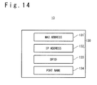
- Fig. 14 is a view showing one example of the structure of the device data 13 that is used in the address spoofing verification in the third exemplary embodiment.
- the device data 13 includes: a MAC address 131 and an IP address 132 (when the two addresses are collectively called, it is referred to as device address information 130) assigned to the legal network device 30 which is allowed to be connected to the system; a DPID 133 of the OFS 4 to which the physical network interface of the network device 30 is connected; and a port name 134 of the OFS 4.
- Each of the MAC address 131, the IP address 132, the DPID 133 and the port name 134 is correlated with each network device 30 and recorded as the device data 13 in the input device 1'.
- the device data 13 is recorded in advance from the input device 1' to the device database in the OFC 2' (Steps S41 and S42).
- the device data 13 given by the input device 1' is supplied to the address spoofing detecting section 21 and stored in the device database 25 (Steps S41 and S42). Consequently, the device database 25 is updated on the basis of the newest device data 13.
- the device database 25 can be always retrieved by the address spoofing detecting section 21.
- the device database 25 may be updated during the operation of the system.
- the network device 30 transmits a Gratuitous ARP packet or an IP packet (Step S43). At this time, the packet from the network device 30 is transferred to the OFS 4.
- the OFS 4 judges whether header information of the Gratuitous ARP packet or IP packet received from a port connected to the network device 30 complies (coincides) with a rule of the flow entry set for itself. If there is a complying rule, the received packet is treated in accordance with the action corresponding to the rule (for example, transferring to the different OFS 4 or discarding) (which is not shown). On the other hand, if (a rule in) the flow entry complying (coinciding) with the header information of the received packet is not set, the OFS 4 notifies the flow controlling section 22 in the OFC 2' of the received packet as the first packet (Step S44). Here, the OFS 4 transmits the first packet or the header information of the first packet together with the DPID 63 of the OFS 4, to the flow controlling section 22 on the basis of the PacketIN.
- the flow controlling section 22 to which the PacketIN is done extracts the verification information 6 from the information transmitted from the OFS 4 together with an asynchronous event and outputs to the address spoofing detecting section 21 (Step S45).
- the address spoofing detecting section 21 extracts the transmission source address information 60 from the verification information 6 received together with the asynchronous event, and verifies the transmission source address of the first packet by using the device database 25 (Step S46: MAC Address ⁇ IP Address Verification). In detail, the address spoofing detecting section 21 verifies whether the device address information 130 (the MAC address 131 and the IP address 132) coincident with the transmission source address information 60 (the transmission source MAC address 61, the target IP address 62 or the transmission source IP address 65) exists in the device database 25 (MAC Address ⁇ IP Address Verification).
- the address spoofing detecting section 21 judges that one or both of the MAC address and the IP address is spoofed, and instructs the flow controlling section 22 to discard the packet (Step S48).
- Step S46 if the device address information 130 coincident with the transmission source address information 60 exists in the device database 25, the port name 134 corresponding to the device address information 130 is compared with the reception port number 64 obtained by the PacketIN. (Step S47: Reception port Verification) . At the step S47, if the port name 134 does not coincide with the reception port number 64, the address spoofing detecting section 21 judges that the reception port name is spoofed and instructs the flow controlling section 22 to discard the packet (Step S48).
- Step S47 if the port name 114 coincides with the reception port number 64, the address spoofing detecting section 21 judges that there is no address spoofing with regard to the first packet and instructs the flow controlling section 22 to set the flow entry for transferring the packet (Step S48)
- the execution sequence of the MAC address ⁇ IP address verification at the step S46 and the reception port verification at the step S47 is not limited to the execution sequence shown in Fig. 15 . So, these verifications may be executed at the opposite order or at the same time. Also, at the time of the MAC address ⁇ IP address verification or reception port verification, the coincidence between the DPID 133 in the device database 25 and the DPID 63 notified by the PacketIN may be verified.
- the flow controlling section 22 which is instructed to discard the packet, discards the first packet of the PacketIN, and sets a flow entry, in which a part or all of the header information of the packet is used as a rule and packet discarding is used as an action, to the OFS 4 (Step S49). Consequently, if the OFS 4 receives the packet which is judged once whether it is spoofed, the packet is discarded without any notification to the OFC 2', and the invasion to the network of the illegal packet can be blocked at the entrance of the network.
- the flow controlling section 22 which is instructed to transfer the packet, sets a flow entry, in which a part or all of the header information of the first packet of the PacketIN, is used as a rule and packet transferring is used as an action, to the OFS 4 on the communication route (Step S49).
- the output device 5 visibly outputs the transmission source address information 60 (the transmission source MAC address 61 and the target IP address 62 or the transmission source IP address 65) as a spoofed address.
- the address spoofing detecting section 21, when judging that the address is spoofed may output the reception port number 64 to the output device 5. In this case, the output device 5 visibly outputs the reception port number 64.
- Fig. 16 is a view showing the specific example to describe the configuration and operation of the computer system in the third exemplary embodiment.
- the device database 25 registers, as the device data 13, the device address information 130: the MAC address 131: "MAC-d” and the IP address 132: "IP-d”, the DPID 133: "SwitchA (DPID 01)", and the port name 134: "Port-X”.
- the network device 30 has one interface "IF-d”.
- the OFS 4 "OpenFlow SwitchA" is connected through the port "Port-X" to the network device 30.
- the network monitoring operation in the foregoing computer system will be described.
- the packet is transferred through the port "Port-X" to the OFS 4 "OpenFlow SwitchA".
- the OFS 4 "OpenFlow SwitchA" does the PacketIN of the received packet as the first packet to the flow controlling section 22.
- the flow controlling section 22 notifies the address spoofing detecting section 21 of the verification information 6 together with the asynchronous event in response to the PacketIN.
- the transmission source MAC address 61 "MAC-d”
- the target IP address 62 “IP-d”
- the DPID 63 "DPID 01”
- the reception port number 64 "Port-X” are notified as the verification information 6.
- the address spoofing detecting section 21 carries out the MAC address ⁇ IP address verification by using the notified transmission source MAC address 61 "MAC-d” and target IP address 62 "IP-d".
- the address spoofing detecting section 21 extracts the port name 134 "Port-X" corresponding to the device address information 130.
- the address spoofing detecting section 21 carries out the reception port verification.
- the reception port number 64: "Port-X" received by the Packet IN coincides with the port name 134 "Port-X" extracted from the device database 25.
- the reception port verification it is judged that there is no spoofed address.
- the coincidence between the DPID 133 in the device database 25 and the DPID 133 received by the PacketIN may be verified.
- the DPID 133 "DPID 01" coincides with the DPID 133 "DPID 01". Hence, it is judged that there is no spoofed address.
- the address spoofing detecting section 21 judges, since judging that there is no spoofing as the result of all of the address spoofing verifications, that the Gratuitous ARP packet notified as the first packet uses the legal transmission source MAC address and target IP address, and then instructs the flow controlling section 22 to transfer the packet.
- the flow controlling section 22 sets, for example, a flow entry defining a rule of the transmission source MAC address: "MAC-d” and the target IP address: "IP-d” and an action of "transferring to the different OFS 4", to the OFS 4 "OpenFlow SwitchA". Consequently, the OFS 4 "OpenFlow SwitchA" , when receiving the ARP packet complying with the set rule, transfers the packet to the specified different OFS 4.
- the flow controlling section 22 sets, for example, a flow entry defining a rule of the transmission source MAC address: "MAC-d” and the target IP address: "IP-a” and an action of "discarding of a packet" , to the OFS 4 ""OpenFlow SwitchA", in response to the packet discarding instruction from the address spoofing detecting section 21. Consequently, the OFS 4 "OpenFlow SwitchA", when receiving the ARP packet complying with the set rule, discards the packet.
- the verification information 6 which is supplied together with the asynchronous event to the address spoofing detecting section 21 is visibly outputted by the output device 5.
- the computer system in the third exemplary embodiment it is possible to monitor the address spoofing packet between the network devices which use the openflow protocol and block the invasion to the network.
- the spoofing of the reception port is verified by obtaining the port number (reception port number) to which the virtual switch is connected from the host OS.
- the notification source of the first packet is the physical switch, the spoofing of the reception port can be verified by using the pre-registered port name.
- the other effects of the computer system according to the third exemplary embodiment are similar to the first exemplary embodiment.
- the exemplary embodiments of the present invention have been described in detail. However, the specific configurations are not limited to the above-mentioned exemplary embodiments. The modification without departing from the scope and spirit of the present invention is included in the present invention. Also, the first, second and third exemplary embodiments can be combined in the scope without any technical conflict. For example, the present invention can be applied to a computer system in which any of the virtual servers 3 and 3' and the network device 30 is installed.
- the OFCs 2 and 2' obtain information of the virtual machine (the transmission source information 7) with the PacketIN, as a trigger.
- the information of the virtual machine in the system may be held as a database.
- the OFCs 2 and 2' may transiently hold the information of the virtual machine (the transmission source information 7) obtained with the PacketIN as a trigger. After that, it may be used in the address spoofing verification for the first packet reported from the OFVS 33 or OFS 4.
- the OFS and OFVS that are used in the computer system according to the present invention may be operated in accordance with the conventional openflow protocol (for example, the protocol defined by OpenFlow Switch Specification version 1.0).
- the conventional openflow protocol for example, the protocol defined by OpenFlow Switch Specification version 1.0.
Landscapes
- Engineering & Computer Science (AREA)
- Signal Processing (AREA)
- Computer Networks & Wireless Communication (AREA)
- Computer Security & Cryptography (AREA)
- Computer Hardware Design (AREA)
- General Engineering & Computer Science (AREA)
- Computing Systems (AREA)
- Software Systems (AREA)
- Theoretical Computer Science (AREA)
- Physics & Mathematics (AREA)
- General Physics & Mathematics (AREA)
- Data Exchanges In Wide-Area Networks (AREA)
- Small-Scale Networks (AREA)
Applications Claiming Priority (2)
| Application Number | Priority Date | Filing Date | Title |
|---|---|---|---|
| JP2010275002 | 2010-12-09 | ||
| PCT/JP2011/077933 WO2012077603A1 (ja) | 2010-12-09 | 2011-12-02 | コンピュータシステム、コントローラ、及びネットワーク監視方法 |
Publications (1)
| Publication Number | Publication Date |
|---|---|
| EP2651081A1 true EP2651081A1 (de) | 2013-10-16 |
Family
ID=46207091
Family Applications (1)
| Application Number | Title | Priority Date | Filing Date |
|---|---|---|---|
| EP11847623.3A Withdrawn EP2651081A1 (de) | 2010-12-09 | 2011-12-02 | Computersystem, steuerung dafür und netzwerküberwachungsverfahren |
Country Status (5)
| Country | Link |
|---|---|
| US (1) | US9118716B2 (de) |
| EP (1) | EP2651081A1 (de) |
| JP (2) | JP5532458B2 (de) |
| CN (1) | CN103250392B (de) |
| WO (1) | WO2012077603A1 (de) |
Cited By (2)
| Publication number | Priority date | Publication date | Assignee | Title |
|---|---|---|---|---|
| WO2015092954A1 (en) * | 2013-12-18 | 2015-06-25 | International Business Machines Corporation | Software-defined networking (sdn) for management of traffic between virtual processors |
| WO2016003389A1 (en) * | 2014-06-30 | 2016-01-07 | Hewlett-Packard Development Company, L.P. | Inject probe transmission to determine network address conflict |
Families Citing this family (31)
| Publication number | Priority date | Publication date | Assignee | Title |
|---|---|---|---|---|
| JP5668503B2 (ja) * | 2011-02-01 | 2015-02-12 | 日本電気株式会社 | 有害サイトフィルタリングシステム及びフィルタリング方法 |
| US8924787B2 (en) * | 2012-01-24 | 2014-12-30 | Nec Laboratories America, Inc. | Network debugging |
| JP5992245B2 (ja) * | 2012-08-06 | 2016-09-14 | 日本電信電話株式会社 | 仮想マシンのマイグレーションシステムおよびその方法 |
| JP2015530763A (ja) * | 2012-08-30 | 2015-10-15 | 日本電気株式会社 | アクセス制御システム、アクセス制御方法及びプログラム |
| CN103905383B (zh) * | 2012-12-26 | 2017-11-24 | 华为技术有限公司 | 一种数据报文转发方法、装置和系统 |
| US20140282542A1 (en) * | 2013-03-14 | 2014-09-18 | Infinio Systems Inc. | Hypervisor Storage Intercept Method |
| US9426060B2 (en) * | 2013-08-07 | 2016-08-23 | International Business Machines Corporation | Software defined network (SDN) switch clusters having layer-3 distributed router functionality |
| CN104348819A (zh) * | 2013-08-07 | 2015-02-11 | 上海宽带技术及应用工程研究中心 | 一种软件定义网络中的防火墙系统及其实现方法 |
| JP6394606B2 (ja) | 2013-10-11 | 2018-09-26 | 日本電気株式会社 | 端末装置、端末装置制御方法および端末装置制御プログラム |
| US9634948B2 (en) * | 2013-11-07 | 2017-04-25 | International Business Machines Corporation | Management of addresses in virtual machines |
| CN108667853B (zh) | 2013-11-22 | 2021-06-01 | 华为技术有限公司 | 恶意攻击的检测方法和装置 |
| US9300580B2 (en) | 2013-12-19 | 2016-03-29 | International Business Machines Corporation | Virtual machine network controller |
| CN104767720A (zh) * | 2014-01-08 | 2015-07-08 | 中兴通讯股份有限公司 | 一种软件定义网络中OpenFlow消息跟踪和过滤的方法 |
| US11075948B2 (en) * | 2014-01-10 | 2021-07-27 | Arista Networks, Inc. | Method and system for virtual machine aware policy management |
| US10523704B2 (en) * | 2014-02-05 | 2019-12-31 | Verve Wireless, Inc. | Methods and apparatus for identification and ranking of synthetic locations for mobile applications |
| US20150341377A1 (en) * | 2014-03-14 | 2015-11-26 | Avni Networks Inc. | Method and apparatus to provide real-time cloud security |
| US9680708B2 (en) | 2014-03-14 | 2017-06-13 | Veritas Technologies | Method and apparatus for cloud resource delivery |
| WO2015155997A1 (ja) * | 2014-04-11 | 2015-10-15 | 日本電気株式会社 | 設定装置、制御装置、設定方法及びネットワークスイッチ |
| CN106385365B (zh) | 2015-08-07 | 2019-09-06 | 新华三技术有限公司 | 基于开放流Openflow表实现云平台安全的方法和装置 |
| US10701104B2 (en) * | 2015-08-18 | 2020-06-30 | Acronis International Gmbh | Agentless security of virtual machines using a network interface controller |
| DE102016221233B3 (de) * | 2016-10-27 | 2017-09-14 | Volkswagen Aktiengesellschaft | Verfahren zum Verwalten einer ersten Kommunikationsverbindung, System umfassend einen ersten Kommunikationspartner und einen zweiten Kommunikationspartner sowie Fahrzeug |
| US20200128029A1 (en) * | 2017-03-13 | 2020-04-23 | Nec Corporation | Network device, monitoring and control device, network system, and control method therefor |
| WO2018220638A1 (en) * | 2017-06-01 | 2018-12-06 | Telefonaktiebolaget Lm Ericsson (Publ) | Optimizing service node monitoring in sdn |
| WO2019111466A1 (ja) * | 2017-12-08 | 2019-06-13 | 日本電気株式会社 | 情報処理装置、仮想化インフラストラクチャ管理装置、仮想ネットワーク機能の管理方法及びプログラム |
| CN108600158B (zh) * | 2018-03-08 | 2020-05-22 | 清华大学 | 一种基于软件定义网络的源地址验证系统 |
| CN109413675A (zh) * | 2018-12-05 | 2019-03-01 | 斑马网络技术有限公司 | 车联网流量控制方法、装置及车载终端 |
| US11303548B2 (en) * | 2020-07-31 | 2022-04-12 | Bank Of America Corporation | Network directionality mapping system |
| KR102379721B1 (ko) * | 2021-09-03 | 2022-03-29 | 프라이빗테크놀로지 주식회사 | Tcp 세션 제어에 기초하여 애플리케이션의 네트워크 접속을 제어하기 위한 시스템 및 그에 관한 방법 |
| CN113904984B (zh) * | 2021-10-21 | 2022-12-16 | 杭州志卓科技股份有限公司 | 一种适用于sap与b2b系统的数据传输方法 |
| CN114666300B (zh) * | 2022-05-20 | 2022-09-02 | 杭州海康威视数字技术股份有限公司 | 基于多任务的双向连接阻断方法、装置及电子设备 |
| US11983164B1 (en) | 2022-11-17 | 2024-05-14 | Bank Of America Corporation | System and method for data community detection via data network telemetry |
Family Cites Families (7)
| Publication number | Priority date | Publication date | Assignee | Title |
|---|---|---|---|---|
| US7234163B1 (en) * | 2002-09-16 | 2007-06-19 | Cisco Technology, Inc. | Method and apparatus for preventing spoofing of network addresses |
| US7562390B1 (en) * | 2003-05-21 | 2009-07-14 | Foundry Networks, Inc. | System and method for ARP anti-spoofing security |
| US7516487B1 (en) * | 2003-05-21 | 2009-04-07 | Foundry Networks, Inc. | System and method for source IP anti-spoofing security |
| JP2005210451A (ja) | 2004-01-23 | 2005-08-04 | Fuji Electric Holdings Co Ltd | 不正アクセス防止装置及びプログラム |
| JP5240784B2 (ja) | 2009-05-29 | 2013-07-17 | 株式会社吉野工業所 | 閉鎖弁付きエアゾール容器 |
| CN101883090A (zh) | 2010-04-29 | 2010-11-10 | 北京星网锐捷网络技术有限公司 | 一种客户端的接入方法、设备及系统 |
| KR101270041B1 (ko) * | 2011-10-28 | 2013-05-31 | 삼성에스디에스 주식회사 | Arp 스푸핑 공격 탐지 시스템 및 방법 |
-
2011
- 2011-12-02 WO PCT/JP2011/077933 patent/WO2012077603A1/ja not_active Ceased
- 2011-12-02 JP JP2012547830A patent/JP5532458B2/ja not_active Expired - Fee Related
- 2011-12-02 US US13/991,409 patent/US9118716B2/en not_active Expired - Fee Related
- 2011-12-02 EP EP11847623.3A patent/EP2651081A1/de not_active Withdrawn
- 2011-12-02 CN CN201180058912.9A patent/CN103250392B/zh active Active
-
2014
- 2014-04-16 JP JP2014084197A patent/JP5790827B2/ja not_active Expired - Fee Related
Non-Patent Citations (1)
| Title |
|---|
| See references of WO2012077603A1 * |
Cited By (2)
| Publication number | Priority date | Publication date | Assignee | Title |
|---|---|---|---|---|
| WO2015092954A1 (en) * | 2013-12-18 | 2015-06-25 | International Business Machines Corporation | Software-defined networking (sdn) for management of traffic between virtual processors |
| WO2016003389A1 (en) * | 2014-06-30 | 2016-01-07 | Hewlett-Packard Development Company, L.P. | Inject probe transmission to determine network address conflict |
Also Published As
| Publication number | Publication date |
|---|---|
| JP5532458B2 (ja) | 2014-06-25 |
| JP5790827B2 (ja) | 2015-10-07 |
| WO2012077603A1 (ja) | 2012-06-14 |
| JP2014147120A (ja) | 2014-08-14 |
| US9118716B2 (en) | 2015-08-25 |
| CN103250392A (zh) | 2013-08-14 |
| CN103250392B (zh) | 2016-12-14 |
| JPWO2012077603A1 (ja) | 2014-05-19 |
| US20130254891A1 (en) | 2013-09-26 |
Similar Documents
| Publication | Publication Date | Title |
|---|---|---|
| US9118716B2 (en) | Computer system, controller and network monitoring method | |
| US7360242B2 (en) | Personal firewall with location detection | |
| EP1969777B1 (de) | Verfahren zum Betrieb von mehreren virtuellen Netzwerken | |
| US9065815B2 (en) | Computer system, controller, and method of controlling network access policy | |
| US7725932B2 (en) | Restricting communication service | |
| JP5062967B2 (ja) | ネットワークアクセス制御方法、およびシステム | |
| US9160771B2 (en) | Method and apparatus for dynamic destination address control in a computer network | |
| WO2005036831A1 (ja) | フレーム中継装置 | |
| US20160359808A1 (en) | Load balancing among a cluster of firewall security devices | |
| KR101290963B1 (ko) | 가상화 기반 망분리 시스템 및 방법 | |
| EP2600566A1 (de) | Steuerverfahren zum blockieren unerwünschter zugriffe | |
| US10834052B2 (en) | Monitoring device and method implemented by an access point for a telecommunications network | |
| JP2008271242A (ja) | ネットワーク監視装置、ネットワーク監視用プログラム、およびネットワーク監視システム | |
| JP2008306610A (ja) | 不正侵入・不正ソフトウェア調査システム、および通信振分装置 | |
| US11159533B2 (en) | Relay apparatus | |
| WO2021123491A1 (en) | Protection against malicious data traffic | |
| JP4852379B2 (ja) | パケット通信装置 | |
| KR101977612B1 (ko) | 네트워크관리장치 및 방법 | |
| KR101914831B1 (ko) | 호스트 추적 서비스에 대한 공격을 방지할 수 있는 소프트웨어 정의 네트워크 및 이에 포함되는 컨트롤러 | |
| KR101854996B1 (ko) | 악성 애플리케이션을 방지할 수 있는 소프트웨어 정의 네트워크 및 이에 포함되는 판단 장치 | |
| KR102628441B1 (ko) | 네트워크 보호 장치 및 그 방법 | |
| JP3739772B2 (ja) | ネットワークシステム |
Legal Events
| Date | Code | Title | Description |
|---|---|---|---|
| PUAI | Public reference made under article 153(3) epc to a published international application that has entered the european phase |
Free format text: ORIGINAL CODE: 0009012 |
|
| 17P | Request for examination filed |
Effective date: 20130626 |
|
| AK | Designated contracting states |
Kind code of ref document: A1 Designated state(s): AL AT BE BG CH CY CZ DE DK EE ES FI FR GB GR HR HU IE IS IT LI LT LU LV MC MK MT NL NO PL PT RO RS SE SI SK SM TR |
|
| DAX | Request for extension of the european patent (deleted) | ||
| STAA | Information on the status of an ep patent application or granted ep patent |
Free format text: STATUS: THE APPLICATION HAS BEEN WITHDRAWN |
|
| 18W | Application withdrawn |
Effective date: 20170915 |