EP2651111A2 - Vorrichtungskooperationssystem, Funktion mit Bereitstellung eines Verfahrens - Google Patents
Vorrichtungskooperationssystem, Funktion mit Bereitstellung eines Verfahrens Download PDFInfo
- Publication number
- EP2651111A2 EP2651111A2 EP12183088.9A EP12183088A EP2651111A2 EP 2651111 A2 EP2651111 A2 EP 2651111A2 EP 12183088 A EP12183088 A EP 12183088A EP 2651111 A2 EP2651111 A2 EP 2651111A2
- Authority
- EP
- European Patent Office
- Prior art keywords
- output
- mfp
- user
- authentication
- unit
- Prior art date
- Legal status (The legal status is an assumption and is not a legal conclusion. Google has not performed a legal analysis and makes no representation as to the accuracy of the status listed.)
- Ceased
Links
Images


Classifications
-
- G—PHYSICS
- G06—COMPUTING OR CALCULATING; COUNTING
- G06K—GRAPHICAL DATA READING; PRESENTATION OF DATA; RECORD CARRIERS; HANDLING RECORD CARRIERS
- G06K15/00—Arrangements for producing a permanent visual presentation of the output data, e.g. computer output printers
-
- H—ELECTRICITY
- H04—ELECTRIC COMMUNICATION TECHNIQUE
- H04N—PICTORIAL COMMUNICATION, e.g. TELEVISION
- H04N1/00—Scanning, transmission or reproduction of documents or the like, e.g. facsimile transmission; Details thereof
- H04N1/00127—Connection or combination of a still picture apparatus with another apparatus, e.g. for storage, processing or transmission of still picture signals or of information associated with a still picture
- H04N1/00347—Connection or combination of a still picture apparatus with another apparatus, e.g. for storage, processing or transmission of still picture signals or of information associated with a still picture with another still picture apparatus, e.g. hybrid still picture apparatus
-
- H—ELECTRICITY
- H04—ELECTRIC COMMUNICATION TECHNIQUE
- H04N—PICTORIAL COMMUNICATION, e.g. TELEVISION
- H04N1/00—Scanning, transmission or reproduction of documents or the like, e.g. facsimile transmission; Details thereof
-
- H—ELECTRICITY
- H04—ELECTRIC COMMUNICATION TECHNIQUE
- H04N—PICTORIAL COMMUNICATION, e.g. TELEVISION
- H04N1/00—Scanning, transmission or reproduction of documents or the like, e.g. facsimile transmission; Details thereof
- H04N1/00832—Recording use, e.g. counting number of pages copied
-
- H—ELECTRICITY
- H04—ELECTRIC COMMUNICATION TECHNIQUE
- H04N—PICTORIAL COMMUNICATION, e.g. TELEVISION
- H04N1/00—Scanning, transmission or reproduction of documents or the like, e.g. facsimile transmission; Details thereof
- H04N1/32—Circuits or arrangements for control or supervision between transmitter and receiver or between image input and image output device, e.g. between a still-image camera and its memory or between a still-image camera and a printer device
- H04N1/32502—Circuits or arrangements for control or supervision between transmitter and receiver or between image input and image output device, e.g. between a still-image camera and its memory or between a still-image camera and a printer device in systems having a plurality of input or output devices
- H04N1/32545—Distributing a job or task among a plurality of input devices or a plurality of output devices
- H04N1/32555—Large jobs, i.e. performing identical parts of the same job on different devices
-
- H—ELECTRICITY
- H04—ELECTRIC COMMUNICATION TECHNIQUE
- H04N—PICTORIAL COMMUNICATION, e.g. TELEVISION
- H04N1/00—Scanning, transmission or reproduction of documents or the like, e.g. facsimile transmission; Details thereof
- H04N1/44—Secrecy systems
-
- H—ELECTRICITY
- H04—ELECTRIC COMMUNICATION TECHNIQUE
- H04N—PICTORIAL COMMUNICATION, e.g. TELEVISION
- H04N1/00—Scanning, transmission or reproduction of documents or the like, e.g. facsimile transmission; Details thereof
- H04N1/44—Secrecy systems
- H04N1/4406—Restricting access, e.g. according to user identity
- H04N1/4413—Restricting access, e.g. according to user identity involving the use of passwords, ID codes or the like, e.g. PIN
-
- H—ELECTRICITY
- H04—ELECTRIC COMMUNICATION TECHNIQUE
- H04N—PICTORIAL COMMUNICATION, e.g. TELEVISION
- H04N1/00—Scanning, transmission or reproduction of documents or the like, e.g. facsimile transmission; Details thereof
- H04N1/44—Secrecy systems
- H04N1/4406—Restricting access, e.g. according to user identity
- H04N1/4433—Restricting access, e.g. according to user identity to an apparatus, part of an apparatus or an apparatus function
-
- H—ELECTRICITY
- H04—ELECTRIC COMMUNICATION TECHNIQUE
- H04N—PICTORIAL COMMUNICATION, e.g. TELEVISION
- H04N2201/00—Indexing scheme relating to scanning, transmission or reproduction of documents or the like, and to details thereof
- H04N2201/0008—Connection or combination of a still picture apparatus with another apparatus
- H04N2201/001—Sharing resources, e.g. processing power or memory, with a connected apparatus or enhancing the capability of the still picture apparatus
-
- H—ELECTRICITY
- H04—ELECTRIC COMMUNICATION TECHNIQUE
- H04N—PICTORIAL COMMUNICATION, e.g. TELEVISION
- H04N2201/00—Indexing scheme relating to scanning, transmission or reproduction of documents or the like, and to details thereof
- H04N2201/0077—Types of the still picture apparatus
- H04N2201/0094—Multifunctional device, i.e. a device capable of all of reading, reproducing, copying, facsimile transception, file transception
Definitions
- the present invention relates to a device cooperation system in which plural devices connected via a network take partial charge of providing functions of the devices.
- Device cooperation There is known a processing format referred to as device cooperation, by which plural devices connected in a network cooperate with each other to execute a single job.
- Device cooperation means, for example, that plural devices take partial charge of providing functions necessary for a single job constituted by a series of processes starting from input to output.
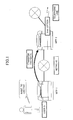
- FIG. 1 illustrates an example of executing a job by device cooperation.
- An MFP (multifunction peripheral) 1 and an MFP 2 are connected to each other via a network.
- the MFP 1 does not have a fax function, but the MFP 2 has a fax function.
- a user Q wants to transmit image data by fax, but because the MFP 1 does not have a fax function, the user Q uses the MFP 1 to scan an original document by the scanner function, and use the fax function of the MFP 2 to transmit the image data by fax.
- FIG. 2 illustrates another example of executing a job by device cooperation.
- Both the MFP 1 and the MFP 2 have a printing function.
- the user Q wants to print out plural copies of the image data.
- the printing operation can be done with only the MFP 1; however, by having the MFP 2 take partial charge of the printing operation, the printing operation can be completed quickly.
- the user Q may operate the MFP 1 to scan the original document with the scanning function, and transmit the image data and print conditions to the MFP 2, so that the printing operation is shared by the MFP1 and the MFP 2.
- Patent Document 1 discloses the following service execution device.
- the service execution device transmits, to a server, a usage request for authentication information and a usage request of a scheduled number of sheets to be used.
- the service execution device executes a job based on user instructions with the scheduled number of sheets to be used set as the upper limit.
- Patent Document 1 Although it is possible to authenticate a user by a server so that authentication for plural devices can be performed at once, the user Q cannot be authenticated unless there is a server. That is to say, in a case where the respective devices are to authenticate the user instead of the server, no consideration is made as to how the MFP 2 authenticates the user Q. For example, when the user Q does not have the authority to use the MFP 2, the user Q is not to be allowed to use the MFP 2 in device cooperation. Furthermore, even if the user Q has the authority to use the MFP 2, if the MFP 2 cannot authenticate the user Q, it is not possible to count or limit the usage amount of the user Q. Accordingly, in the conventional device cooperation system, the usage amount of the user cannot be accurately limited when device cooperation is performed.
- Patent Document 1 Japanese Laid-Open Patent Publication No. 2010-074431
- the present invention provides a device cooperation system and a function providing method, in which one or more of the above-described disadvantages are eliminated.
- a preferred embodiment of the present invention provides a device cooperation system and a function providing method by which the usage amount of a user can be limited when device cooperation is performed, even when there is no server used for authentication.
- a device cooperation system including plural devices connected via a network, which take partial charge of providing a function of the plural devices, wherein a first device operated by a user includes a first authentication unit configured to authenticate the user, an acquiring unit configured to acquire image data that is an output target, an output condition receiving unit configured to receive an output condition used when the first device and at least one second device output the image data, a first operation control unit configured to control an output operation of the first device based on the output condition, and send an output request to the at least one second device, a first storage unit configured to store a first possible output amount that the user can output with the first device, an allocation number determining unit configured to determine a first output number to be allocated to the first device and a second output number to be allocated to the at least one second device, a data communication unit configured to send the image data, the second output number, and user information of the user to the at least one second device, a first output unit configured to output an output object corresponding to the first output number, when
- a function providing method by which plural devices connected via a network take partial charge of providing a function of the plural devices, the function providing method including authenticating a user operating a first device, performed by a first authentication unit; acquiring image data that is an output target, performed by an acquiring unit; receiving an output condition used when the first device and at least one second device output the image data, performed by an output condition receiving unit; controlling an output operation of the first device based on the output condition and sending an output request to the at least one second device, performed by a first operation control unit; determining a first output number to be allocated to the first device and a second output number to be allocated to the at least one second device, performed by an allocation number determining unit; outputting an output object corresponding to the first output number performed by a first output unit, when the first output number is less than or equal to a first possible output amount stored in a first storage unit, the first possible output amount being an amount that the user can output with the first device; sending the image data, the second output
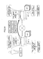
- FIGS. 3A and 3B schematically illustrate a device cooperation system 200 according to the present embodiment.
- An MFP (multifunction peripheral) 1 and an MFP 2 (hereinafter, referred to as "MFP 100" when not distinguished from each other) can execute a single job by cooperating with each other.
- MFP 100 multifunction peripheral
- This system in which plural devices provide functions to each other is referred to as the device cooperation system 200.
- a job that is executed by two or more MFPs in cooperation with each other is referred to as a device cooperation job.
- FIG. 3A schematically illustrates procedures performed by the MFP 1 and the MFP 2 for executing a device cooperation job of a copy application.
- the MFP 1 and the MFP 2 respectively store the possible usage amount in which the remaining number of pages that the user Q can use is registered, in the usage amount limit information.
- the possible usage amount of the MFP 1 is, for example, the number of pages that the user Q can output with the MFP 1
- the possible usage amount of the MFP 2 is, for example, the number of pages that the user Q can output with the MFP 2.
- image data corresponding to one side of a sheet is referred to as one page, regardless of whether the pages are combined or the amount of toner used, and the minimum unit of a sheet material is referred to as one page, regardless of single-sided printing or double-sided printing.
- a PC personal computer
- the PC transmits print conditions and image data of the device cooperation job to the MFP 1, and thereafter the MFP 1 performs processing as in the case of the copy application.
- FIG. 3B schematically illustrates procedures performed by the MFP 1 and the MFP 2 for executing a device cooperation job of a fax application.
- the MFP 1 determines the allocation, and the MFP 1 and the MFP 2 have a fax function. However, even if the MFP 1 does not have a fax function, if an MFP 3 (not shown) has a fax function, the MFP 1 determines the number of pages to be allocated to the MFP 2 and the MFP 3.
- the MFP 1 authenticates the user Q
- the MFP 2 authenticates the user Q
- the usage amounts are allocated, and fax transmission is performed within the possible usage amount. Therefore, even for a different application, the authentication method and the limitation of the usage amount according to the present embodiment are applicable.
- Device cooperation includes all formats where one MFP uses the function of the other MFP. That is to say, cases in which a job is not executed or an application is not operating are also referred to as device cooperation.
- the MFP 1 and the MFP 2 often operate for each application, and therefore a description is given by taking an application as an example. In the description, it is assumed that the device operated by the user is the MFP 1.
- the application identifies a combination of one of the plural input units of the MFP and one of the plural output units of the MFP, and controls devices and provides functions based on the identified combination.
- FIGS. 4A through 4D illustrate examples of formats of device cooperation of the MFP 1 and the MFP 2.
- FIGS. 4A through 4D illustrate a copy application, a scanner application, and a transmission application; however, other applications may also be implemented by having the MFP 1 and the MFP 2 provide functions to each other.
- a single job goes through the processes of scanning an original document by a scanner function, image processing, printing, and post-processing (finishing).
- Image processing is, for example, OCR processing and confidential print processing.
- Post-processing is, for example, hole punching and stapling. These processes are not frequently used.
- a single job goes through the processes of scanning an original document by a scanner function, image processing, and transmitting.
- the image processing is, for example, OCR processing, PDF conversion, and encryption processing. These processes are not frequently used.
- Transmission includes the processes of, for example, transmitting by email or transmitting to a folder of the user Q.
- a single job goes through the processes of scanning an original document by a scanner function, image processing, and fax transmission.
- Image processing is, for example, OCR processing and confidential print processing. These processes are not frequently used.
- Fax transmission is, for example, fax transmission using a telephone line or an IP network.
- device cooperation may be performed without executing a device cooperation job.
- the user Q may input instructions in the MFP 1 to read the image data stored in the MFP 2 from the MFP 1 and process the image data.
- the process may include printing, e-mail transmission, and fax transmission.
- the process may include deleting image data of the MFP 2 by the MFP 1, and displaying a preview of image data of the MFP 2 by the MFP 1.
- a format of device cooperation is created.
- FIGS. 4A through 4D describe device corporation of two MFPs; however, there may be cases where three or more MFPs perform device cooperation. In the case of device cooperation performed by three or more MFPs, combinations of MFPs taking charge of editing and outputting increase.
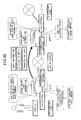
- FIG. 5 illustrates a configuration of the device cooperation system 200.
- a LAN 1 and a LAN 2 form a single WAN.
- the LAN 1 and the LAN 2 are connected by an L3 switch or a router (not shown).
- Device cooperation may be performed when the number of LANs may be one or three or more.
- Communications among the MFP 1 through MFP 4, communications between servers 1 and 2, and communications between the MFP 1 through MFP 4 and a server 300 (hereinafter, referred to as server 1 or 2 when distinguished) may be wired or wireless.
- the MFPs 1 through 4 have at least one function among copying, scanning, fax transmission, and printing.
- the MFPs 1 through 4 do not need to have the same functions.
- the MFPs 1 through 4 may respectively have functions unique to themselves.
- the servers 1 and 2 may be, for example, an information processing apparatus for user authentication or an information processing apparatus for providing functions that the MFPs 1 through 4 do not have (for example, OCR processing, translation processing, and converting file formats), although the servers 1 and 2 are not necessary.
- each MFP has usage amount limit information; however, when the server stores the usage amount limit information of each user, the server 1 or 2 is used.
- the server 1 or 2 not only compares the possible usage amounts of the respective MFPs, but may also compare the total usage amount that the user users the MFPs 1 through 4 with the usage amount limit information.
- the MFPs 1 through 3 form a network through a hub or a LAN switch, and the MFP 2 and the MFP 3 are connected by an IEEE1394 interface.
- one or all of the MFPs may be locally connected (in a peer-to-peer manner).
- the connection interface may be USB or a LAN cable, as long as communications can be performed between the MFPs.
- device cooperation may be performed with the use of the servers 1, 2.
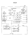
- FIG. 6 illustrates a hardware configuration of the MFP 1, 2.
- the MFP 100 includes a controller 120, an operations panel 130, an FCU (facsimile control unit) 140, a scanner engine 150, and a plotter engine 160.
- FCU facsimile control unit
- the controller 120 includes a CPU 101, an ASIC 113, a NB (north bridge) 102, a SB (south bridge) 106, a MEM-P (system memory) 103, a MEM-C (local memory) 104, a HDD (hard disk drive) 105, a memory card slot 111, a NIC (network interface controller) 107, a USB device 108, an IEEE 1394 device 109, and a centronics device 110.
- the CPU 101 is an IC for executing various kinds of information processing, and executes programs for providing applications and services in parallel in units of processes, by an OS such as UNIX (registered trademark).
- the ASIC 113 is an IC for image processing.
- the NB 102 is a bridge for connecting the CPU 101 and the ASIC 113.
- the SB 106 is a bridge for connecting the NB 102 with peripheral devices.
- the ASIC 113 and the NB 102 are connected via an AGP (Accelerated Graphics Port).
- the MEM-P 103 is a memory connected to the NB 102.
- the MEM-C 104 is a memory connected to the ASIC 113.
- the HDD 105 is a storage connected to the ASIC 113, and is used for storing image data, document data, programs, font data, and form data.
- the memory card slot 111 is connected to the SB 106, and is used for setting (inserting) a memory card 112.
- the memory card 112 is a flash memory such as a USB memory, and is used for distributing a program 115.
- the program 115 may be distributed by being downloaded from a predetermined server to the MFP 100.
- the NIC 107 is a controller for performing data communications using MAC addresses via a network.
- the USB device 108 is a device for providing a serial port in compliance with the USB specification.
- the IEEE 1394 device 109 is a device for providing a serial port in compliance with the IEEE 1394 specification.
- the centronics device 110 is a device for providing a parallel part in compliance with the centronics specification.
- the NIC 107, the USB device 108, the IEEE 1394 device 109, and the centronics device 110 are connected to the NB 102 and the SB 106 via a PCI (Peripheral Component Interconnect) bus.
- PCI Peripheral Component Interconnect
- the operations panel 130 is a hardware component (operation unit) used by the user Q for inputting information in the MFP 100.
- the operations panel 130 includes a display unit 170 that is a hardware component for the MFP 100 to provide visible information to the operator.
- the operations panel 130 is connected to the ASIC 113.
- the FCU 140, the scanner engine 150, and the plotter engine 160 are connected to the ASIC 113 via the PCI bus 114.
- the scanner engine 150 optically scans an original document placed on a contact glass, performs image processing by A/D converting the reflection light from the original document, and generates digital data (hereinafter, image data) having a predetermined resolution.
- the plotter engine 160 includes, for example, tandem type photoconductive drums, and forms latent images by modulating laser beams and scanning the photoconductive drums based on image data and PDL data received from a user PC. An image corresponding to one page developed by applying toner to the latent images is transferred to a sheet by heat and pressure.
- the plotter engine 160 is not limited to a plotter of an electrophotographic type; the plotter engine 160 may be an inkjet type for forming an image by jetting liquid droplets.
- the FCU 140 is connected to a network via the NIC 107, and transmits and receives image data by communication procedures according to the specification of T.37, T.38, for example.
- the FCU 140 is connected to a public communications network, and transmits and receives image data by communication procedures according to specifications of G3, G4, for example.
- G3, G4 for example.
- FIG. 7 is a functional block diagram of the MFP 100.
- the MFP 100 includes an UI unit, a control unit, and hardware.
- the UI unit and hardware are described above.
- a memory 201 corresponds to the MEM-P 103 and the MEM-C 104
- an engine 202 corresponds to the FCU 140, the scanner engine 150, and the plotter engine 160.
- the control unit includes a copy application 11, a printer application 12, a fax application 13, a resource management module 14, a communication management module 15, an engine management module 16, a job management module 17, an authentication module 18, and a counter management module 19. Furthermore, the HDD 105 stores, for example, usage amount limit information 20 and device management information 21.
- the copy application 11, the printer application 12, and the fax application 13 are examples of applications.
- the copy application 11 starts operating
- the printer application 12 starts operating
- the fax application 13 starts operating.
- An OS 22 is a general-purpose operating system such as UNIX (registered trademark), and executes modules and software of applications as processes in parallel.
- the job management module 17 acquires, from the applications, job information of the device cooperation job set by the user Q, and manages the execution of jobs. Specifically, the job management module 17 requests the resource management module 14 to control resources based on job information, and controls screen display, application management, the operation panel, etc., while receiving the state of progress from the resource management module 14. The job management module 17 detects the present number of output sheets and displays the number on the operations panel 130.
- the job management module 17 includes a usage amount determining unit 32, an allocated number determining unit 31, and a user information sending unit 33, which may be positioned anywhere else in the control unit.
- the allocated number determining unit 31 allocates usage amounts to the respective cooperation devices within the limitation of the usage amount limit information 20, in a manner that the printing time and power consumption are advantageous.
- the usage amount is the number of pages in the case of the printer application 12 and the copy application 11, and the usage amount is the number of transmission destinations in the case of the fax application 13.
- the usage amount determining unit 32 determines whether the scheduled number of pages to be output is less than or equal to the possible usage amount.
- the user information sending unit 33 sends the user information to the MFP 2 that is to perform the device cooperation job. Details of the process are given below.
- the resource management module 14 manages resources. When a request to use hardware resources such as the operations panel 130, the FCU 140, the scanner engine 150, the memory 201, the HDD 105, the NIC 107, the USB device 108, the IEEE 1394 device 109, and the centronics device 110 is received from the job management module 17, the resource management module 14 makes adjustments among the applications and controls the applications. Specifically, the resource management module 14 determines whether the requested hardware resource can be used (not used according to another request), and when it can be used, the resource management module 14 reports to the job management module 17 that the requested hardware resource can be used. Furthermore, the resource management module 14 performs usage scheduling of the hardware resource in response to the request from the job management module 17, and controls the engine management module 16.
- hardware resources such as the operations panel 130, the FCU 140, the scanner engine 150, the memory 201, the HDD 105, the NIC 107, the USB device 108, the IEEE 1394 device 109, and the centronics device 110 is received from the job management module 17, the resource management module 14
- the engine management module 16 controls the engine according to the usage schedule secured and created by the resource management module 14. Accordingly, the scanner engine, the plotter engine (monochrome line printer, color line printer), and the FCU actually execute the job.
- the communication management module 15 is a module for providing a service that can be commonly used with respect to applications that require a network, such as device cooperation.
- the communication management module 15 assigns, to the respective applications, data received from the network by protocols and transmits data received from the applications to the network.
- the communication management module 15 includes server daemons such as ftpd, httpd, lpd, snmpd, telnetd, and smtpd, and client functions of the same protocol.
- the authentication module 18 is a module for performing user authentication. In the usage amount limit information 20 described below, in addition to the possible usage amount for each user, the user name and password are registered. The authentication module 18 authenticates the user Q based on whether the combination of the user name and password input to the operations panel 130 by the user Q is stored in the device cooperation system 200. Alternatively, the authentication module 18 may authenticate the user Q by reading, with an IC card reader (not shown), a user ID stored in an IC card held by the user Q.
- the authentication module 18 does not need to be installed in the MFP.
- a case where the authentication module 18 in each MFP authenticates the user is referred to as "local authentication”.
- a case where the server 1 or the server 2 authenticates the user Q is referred to as "network authentication”.
- the authentication result of local authentication is valid only in the MFP that performed the authentication, but in the case of network authentication, the authentication result is valid in MFPs in the network defined in advance.
- the authentication module 18 reports whether authentication is successful to the application.
- the application receives settings of execution conditions of a job, and when the authentication is unsuccessful, the application displays a message such as "authentication is unsuccessful" on the display unit 170.
- the counter management module 19 counts the usage amount, and updates the usage amount in the usage amount limit information 20.
- a description of the usage amount limit information 20 is given below.
- the applications and modules in the control unit are objects having one or more methods, which are executed as processes on the OS 22.
- the processes are executed in units of one or more threads, and the OS 22 assigns these threads to the CPU.
- the OS 22 manages the states of the threads (execution state, waiting state, executable state, etc.), and controls the thread to be assigned to the CPU among the threads that are in an executable state, according to a logic such as priority and round-robin. Accordingly, the processing speed of parallel execution is higher than that of parallel execution performed by switching processes.
- the applications and the modules transmit and receive messages by inter-process communications by executing the method.
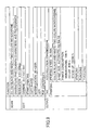
- FIG. 8 illustrates an example of the usage amount limit information 20.
- the usage amount limit information 20 includes user information.
- a "user name”, a "user ID”, a "log-in name”, and a "password” are registered.
- the "user name” is a name or a nickname by which the user Q can be easily identified.
- the "user ID” is one or more numbers, symbols, or alphabetical letters, or a combination thereof, whose uniqueness is ensured in the device cooperation system.
- the "log-in name” is an identification name formed by one-byte letters and numbers that can be easily subjected to computer processing, for flogging into the MFP.
- a "password” is one or more numbers, symbols, or alphabetical letters, or a combination thereof, by which the MFP authenticates the user Q.
- the "upper limit usage amount”, the "usage amount”, and the “possible usage amount” are registered. According to the charging format, an "upper limit usage amount”, a “usage amount”, and a “possible usage amount” are registered both for color and monochrome.
- the “upper limit usage amount” is the usage amount that the user Q can use.
- the “upper limit usage amount” is defined for each user for a particular time period, such as one year, half a year, quarter of a year, a month, and a week.
- the “usage amount” is the amount that the user Q has already used within the time period defined for the "upper limit usage amount”.
- the “possible usage amount” is updated every time a user Q uses a printing function, etc.
- the job management module 17 prohibits printing.
- the "upper limit usage amount”, the “usage amount”, and the “possible usage amount” are registered. However, as long as there is the “possible usage amount”, or the “upper limit usage amount” and the “usage amount”, the usage amount can be managed.
- the usage amount limit information 20 is displayed on the display unit 170, and therefore the user Q can confirm the "possible usage amount”.
- FIG. 9 illustrates an example of the device management information 21.
- functions of the MFP itself are registered.
- readable colors full-color, black-and-white, two-color, or monochrome
- the resolutions 100 through 600 dpi
- the original document type corresponding to the scanning operation characters, photograph, characters/photograph
- fax and printing are registered. Furthermore, in the fax function, a storage transmission function is registered. In the printing function, the printing speed (60 pages/minute), colors that can be output (color, black-and-white, two colors, or monochrome), sheet sizes that can be output (automatic/A4/B4/A3), power consumption (black-and-white printing, color printing, time of standup), stapling, punching, and Z-folding, are registered. As for stapling and punching, the positions on the sheet for performing these functions are also registered.
- the MFP 1 and MFP 2 exchange their device management information 21, so that the processes that the MFP 1 can request to the MFP 2 and the processes that the MFP 2 can request to the MFP 1 can be managed at the MFP 1 and MFP 2.
- the MFP 1 and MFP 2 acquire the device management information 21 of the MFPs that are registered in a list of communication possible devices described below, and save the acquired information in the HDD 105.
- FIG. 10 illustrates the relationship between blocks when the MFP 1 and MFP 2 perform device cooperation.
- the same elements as those of FIG. 7 are denoted by the same reference numerals, and are not further described.
- Option trays 24 and 26 are sheet trays that can be additionally attached, and a finisher 25 is a device for performing stapling, punching, sorting, and binding.
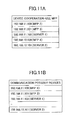
- the communication management module 15 includes a list of communication possible devices 23 of other MFPs and servers that are confirmed as being activated. There are the two following methods for acquiring the list of communication possible devices.
- FIG. 11A illustrates an example of IP addresses of MFPs with which device cooperation is possible.
- the MFP needs to have a function of device cooperation.
- the MFP is not to be intentionally excluded from the targets of device cooperation by the administrator, or the MFP is to be added as the target of device cooperation.
- an MFP that can perform device cooperation is referred to as a "device cooperation-use MFP".
- the IP addresses of device cooperation-use MFPs as viewed from itself are registered.
- the MFP 1 when the MFP 1 is activated, the MFP 1 reports that is has been activated to the device cooperation-use MFPs that are registered in itself and in the network. Accordingly, when the device cooperation-use MFP is activated, the device cooperation-use MFP sends a response, and therefore the MFP 1 registers in the list of communication possible devices that the device cooperation-use MFP from which a response is received is able to communicate. Meanwhile, the device cooperation-use MFPs that are already activated receive that the MFP 1 has been activated and register the MFP 1 in their respective lists of communication possible devices.
- FIG. 11B illustrates an example of a list of communication possible devices.
- the communication management module 15 registers, in the list of communication possible devices, the IP addresses of MFPs that are confirmed as being able to communicate, among the device cooperation-use MFPs. For the IP address of an MFP that cannot be confirmed as being able to communicate, data such as a "-" mark indicating that it is not confirmed as being able to communicate is registered.
- the MFP 1 when the MFP 1 is activated, the MFP 1 broadcasts a broadcast packet requesting to report an IP address to the MFPs that are able to perform device cooperation.
- a broadcast packet in which all transmission addresses are "1" can inquire whether device cooperation is possible, to all devices in the LAN 1.
- a directed broadcast address it is possible to inquire whether device cooperation is possible, to MFPs having network addresses that are specified regardless of routers.
- the network addresses in a network to which the MFPs that can perform device cooperation belong are known by the administrator, and therefore the search range can be easily identified.
- the MFP 1 registers the IP addresses of the detected MFPs 2 through 4, in the list of communication possible devices.
- the user identifies the MFPs 100 for executing a device cooperation job from a list of communication possible devices, and the MFPs 2 to 4 to which user information is sent from the MFP 1 are identified.
- a description is given of procedures performed by the MFP 2 to authenticate the user Q, assuming that the MFP 1 and the MFP 2 execute the device cooperation job.
- FIG. 12 is an example of a flowchart indicating procedures performed by the MFP 1 and the MFP 2 for authenticating a user Q.
- the authentication request includes a user name and a password input by the user Q.
- the authentication module 18 determines whether the user Q can be successfully authenticated based on whether the combination of the user name and the password is registered in the usage amount limit information (step S1).
- step S2 When the authentication is unsuccessful (NO in step S2), the user Q does not have the authority to use the MFP 1, and therefore the process of FIG. 12 ends.
- the user information sending unit 33 of the MFP 1 sends the user information of the user Q to the MFP 2 (step S3).
- the user information to be sent includes the user name and password necessary for user authentication as mandatory information, the log-in date, the log-in device, user type, and the authentication method.
- the log-in date is the date that the user Q has logged into the MFP 1 (when the authentication is successful)
- the log-in device is the identification information (e.g., the IP address) of the MFP 1 which the user Q has logged into
- the user type is information indicating the authority of the user Q such as an administrator
- the authentication method indicates either local authentication or network authentication.
- the user ID and the log-in name may also be sent.
- the timing at which the user information is sent after the user is successfully authenticated may not be immediately after the successful authentication; the timing may be after the devices for executing the device cooperation job are determined.
- the MFP 2 receives the user information of the user Q (step S5).
- the job management module 17 of the MFP 2 sends an authentication request to the authentication module 18.
- the authentication module 18 of the MFP 2 determines whether the user Q can be successfully authenticated based on whether the combination of the user name and the password is registered in the usage amount limit information (step S6).
- the user Q sends the authentication result to the MFP 1 (step S7).
- the MFP 1 receives the authentication result (step S4).
- the authentication result may indicate authentication OK or authentication NG.
- the MFP 1 can allocate a page number to the MFP 2 and start executing the device cooperation job. The case where the MFP 1 receives authentication NG is described below.
- the user information sending unit 33 of the MFP 1 sends the user information to all of the MFPs.
- the copy application 11 receives a setting of execution conditions of a job.
- FIG. 13 illustrates an example of a menu of a device cooperation job displayed on the display unit 170.
- the user Q instructs copying by a device cooperation job
- the user Q presses the copy button of the operations panel 130, or calls a setting screen of the device cooperation job.
- a device search button 301 and a function search button 302 are displayed.
- the device search button 301 is a button for having the MFP 1 search for MFPs in the list of communication possible devices. That is to say, the communication management module 15 confirms that the device cooperation job is possible by communicating with MFPs in the list of communication possible devices, immediately before the device cooperation job.
- the function search button 302 is for having the MFP 1 search for the MFPs 2 through 4 that can provide a function set by the user Q, from among the MFPs in the list of communication possible devices.
- FIG. 13 (b) illustrates an example of a "device cooperation job - device list" screen displayed when the user Q presses the device search button 301.
- the MFP 1 displays a list of the MFPs 2 through 4 (two in FIG. 13 ) that have responded as being able to execute a device cooperation job, among the MFPs in the list of communication possible devices.
- a responding MFP sends its device name and IP address to the MFP 1. At this time, the responding MFP sends the device management information 21.
- the user Q confirms that a target MFP having the desired function is in the list, and presses a condition setting button 311.
- FIG. 13 (d) is an example of a "cooperation job-scan setting" screen displayed when the user Q presses the condition setting button 311.
- a scan setting menu is displayed for each MFP.
- device names are displayed in the tabs 321 as "OWN DEVICE (referring to MFP 1)", “IMAGICS (MFP 2)", and “IPUKS (MFP 3)".
- the user Q can select a MFP for making a scan setting by selecting a tab 321.
- the MFP 1 displays only the valid menus (that can be selected) for the selected MFP, based on the device management information 21.
- the user Q can set scanning conditions such as color selection, original document type, and density, from the valid menus of the selected MFP.
- scanning conditions such as color selection, original document type, and density
- the user Q sequentially selects an edit setting button 322 and a print setting button 323.
- the edit setting button 322 a menu for selecting editing functions that the device can provide is displayed for each MFP.
- the print setting button 323 a menu for selecting printing functions that the device can provide is displayed for each MFP.
- the scan setting the user Q can set conditions for only one MFP, but as for the print setting and edit setting, the user Q can set conditions for plural MFPs or servers. Finally, by pressing an execute button 324, the device cooperation job is started.
- FIG. 13 (c) is an example of a "cooperation job-function search” screen displayed when the user Q presses the function search button 302.
- the MFP 1 displays a menu that can be set for each of the processes of "scanning conditions", “editing conditions”, and “print conditions", from the device management information 21 of other MFPs acquired in the past.
- the user Q selects an appropriate tab to set the "scanning conditions", "editing conditions", and "print conditions” which are search keys.
- the MFP 1 After setting the conditions, when the user Q presses a search button 331, the MFP 1 searches the device management information 21 acquired from another MFP in terms of the "scanning conditions", "editing conditions", and "print conditions". By doing so, it is possible to identify an MFP that can perform scanning according to the "scanning conditions" set by the user Q, an MFP or a server than can perform editing according to the "editing conditions", and an MFP that can perform printing according to the "print conditions”.
- the MFP 1 may display all devices for each of the "scanning conditions", “editing conditions", and “print conditions”, or may narrow down the number of devices to less than or equal to a predetermined number.
- a method of prioritizing the device itself e.g., the MFP 1
- the MFP 1 displays the one or more MFPs that are hit by the search on a screen similar to FIG. 13(d) . That is to say, the MFP 1 displays the MFPs that match the conditions, by the "scan setting", the “edit setting”, and the “print setting”.
- the “scanning conditions”, “editing conditions”, and “print conditions” are set in FIG. 13 (c) , and therefore the user Q does not need to set the conditions again.
- the user Q presses an "execution” button after confirming the MFPs of the processes and conditions. Accordingly, the MFP 1 starts the device cooperation job.
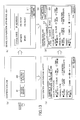
- FIG. 14A illustrates an example of a first screen of the print setting, when the user Q presses the print setting button 323 in FIG. 13 (d) .
- the user may select whether to set print conditions common to plural MFPs, or to set separate print conditions for the respective MFPs. In the case where common settings are selected, the user Q selects more than one MFP. In the case where separate settings are selected, the user Q sets print conditions for the respective MFPs in the next screen.
- the MFP 1 can acquire, from the MFPs in the list of communication possible devices, the elapsed time from the first printing operation and the power consumption for restoring the temperature at which printing is possible (print possible temperature), and display these elements.
- the power consumption may be reduced if the user Q selects an MFP with a short elapsed time since the last printing operation or an MFP having low power consumption for restoring the print possible temperature.
- FIG. 14B illustrates an example of a screen for common settings in print conditions.
- the user Q may set print conditions common to the MFPs, such as color/black-and-white, sheet size, number of copies, and magnification.
- the common print conditions are contents corresponding to the largest common denominator of device management information received from the MFPs in the list of communication possible devices. For example, when the MFP 1 can perform both color printing and black-and-white printing, and the MFP 2 can only perform black-and-white printing, color is not displayed in the "color/black-and-white" menu of FIG. 14B . Similarly, in the "sheet size" menu, only the sheet sizes that can be selected both in the MFP 1 and the MFP 2 are displayed. In the magnification menu, only the magnification range that can be selected both in the MFP 1 and the MFP 2 can be set. Sorting and stapling is displayed only when they can be selected both in the MFP 1 and the MFP 2.
- the set number of copies (or number of pages) is allocated to the MFPs that are the target of common settings.
- the user Q may set whether to allocate a number of copies or a number of pages.
- FIG. 14C illustrates an example of a screen for separate settings in print conditions.
- general print conditions such as sheet size, number of copies, and magnification may be set for each MFP.
- the respective MFPs print out the number of set copies.
- the counter management module 19 counts the usage amount by a method set in advance.
- the following counting methods are merely examples; different counting methods may be used by the devices.
- the engine management module 16 or the resource management module 14 counts the printing number by each page. Every time one page is printed or when the job is completed, the job management module 17 acquires the number of printed pages, counts the printing number according to the above counting methods, and updates the usage amount and the possible usage amount of the usage amount limit information 20. Similarly, in the fax application 13, the engine management module 16 or the job management module 17 counts the number of scanned original documents or the number of pages of the image data. The job management module 17 acquires the number of pages when a job is completed, and updates the usage amount and the possible usage amount of the usage amount limit information 20.
- the copy application 11 in FIG. 10 sends a job execution request to the job management module 17.
- the job management module 17 generates job information from the execution conditions.
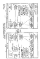
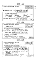
- FIGS. 15A through 15E illustrate an example of job information.
- the device cooperation job is executed in the order of "1. input ⁇ 2. edit ⁇ 3. output”.
- input ⁇ 2. edit ⁇ 3. output For each process, a "device in charge” is registered, and input conditions, edit conditions, and output conditions are registered.
- FIG. 15A illustrates an example of a job of the copy application 11 in which only the MFP 1. performs printing, indicated as a matter of comparison.
- the device in charge of input is the MFP 1
- the device in charge of editing is the MFP 2
- the device in charge of output (printing) is the MFP 1.
- FIG. 15B illustrates an example of a device cooperation job of the copy application 11 printed by the MFP 1 and the MFP 2.
- the device in charge of input is the MFP 1
- the device in charge of editing is the MFP 2
- the devices in charge of output (printing) are the MFP 1 and MFP 2.
- "common settings" is selected in the "print settings”.
- the allocated number determining unit 31 allocates a number of copies to the respective devices in charge (print number).
- the method of determining the number of allocated pages is described below.
- FIG. 15C illustrates an example of the device cooperation job whose print number is allocated to the MFP 1 and MFP 2. Compared to FIG. 15B , two output processes are created, and the MFP 1 and the MFP 2 are set as the respective devices in charge. The method of determining the allocated page number is described below.
- the job management module 17 sends, to the MFP 2, a print request of which the device in charge of output is the MFP 2 together with job information (the whole job information may be sent). In the "print setting", when the user selects "separate settings", the job information of FIG. 15C is directly generated. User authentication is not described here.
- the job management module 17 sends, to the MFP 2, the job information and image data whose device in charge is the MFP 2.
- FIG. 15 (d) illustrates an example of job information of a device cooperation job of a fax application.
- the device in charge of input is the MFP 1
- the device in charge of editing is the MFP 1
- the devices in charge of output are the MFP 1 and MFP 2.
- the user Q sets, in the transmission setting of the scanner application, a plural number of destinations (fax numbers) corresponding to the number of copies of the copy application.
- the allocated number determining unit 31 determines the destinations for each device in charge, in units of destinations. For example, when there are two destinations, and there are two MFPs in charge of fax transmission, each MFP becomes in charge of one destination. When there are an N number of destinations, and there are an M number of MFPs in charge of fax transmission, each MFP become in charge of N/M number of destinations.
- a destination having an area code of 03 is allocated to the MFP 1
- a destination having an area code of 06 is allocated to the MFP 2.
- communication costs can be reduced.
- a table in which the area codes of destinations to be handled by each MFP is prepared.
- FIG. 15E illustrates an example of a device cooperation job whose destinations are allocated to the MFP 1 and the MFP 2.
- the job management module 17 sends, to the MFP 2, the job information whose device in charge of output is the MFP 2 (the whole job information may be sent).
- the job management module 17 sends, to the MFP 2, the job information and image data whose device in charge is the MFP 2.
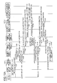
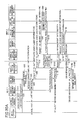
- FIGS. 16A and 16B illustrate a sequence diagram illustrating procedures of authenticating a user Q and executing a device cooperation job performed by the MFP 1 and the MFP 2.
- the copy application 11 is taken as an example.
- the authentication module 18 authenticates the user Q, and reports the authentication result to the copy application (step S10).
- the copy application sends a job execution request for the device cooperation job to the job management module 17 (step S20).
- the job management module 17 executes an input process in cooperation with the resource management module 14 and the engine management module 16 (step S30).
- the job management module 17 requests the counter management module 19 to acquire the usage amount limit information 20 (step S40).
- the counter management module 19 reads the possible usage amount from the usage amount limit information 20, and sends the possible usage amount to the job management module 17 (step S50).
- the user information sending unit 33 requests the communication management module 15 to authenticate the user Q of the MFP 2 (step S60).
- This request includes user information.
- the communication management module 15 of the MFP 1 sends an authentication request for the user Q to the communication management module 15 of the MFP 2 (step S70).
- the communication management module 15 of the MFP 2 sends an authentication request for the user Q to the authentication module 18 (step S80).
- the authentication module 18 of the MFP 2 authenticates the user Q (step S90).
- the authentication module 18 sends the authentication result to the job management module 17 of the MFP 1 (steps S100 through S120). Here, it is assumed that the authentication is successful.
- the job management module 17 requests the communication management module 15 to acquire the device management information 21 from the MFP 2 (step S130).
- the communication management module 15 communicates with the communication management module 15 of the MFP 2 (step S140).
- the communication management module 15 of the MFP 2 requests the resource management module 14 to provide the device management information 21 (step S150).
- the resource management module 14 is not shown in FIGS. 16A and 16B .
- the resource management module 14 reads the device management information 21 and sends the device management information 21 to the communication management module 15 (step S160).
- the communication management module 15 of the MFP 2 sends the device management information 21 to the communication management module 15 of the MFP 1 (step S170).
- the communication management module 15 of the MFP 1 sends the device management information 21 of the MFP 2 to the job management module 17 (step S180).
- the job management module 17 determines the allocated page number for the MFP 1 and the MFP 2 if necessary. "If necessary" means when the user has selected common settings in FIG. 14A . When the user has selected separate settings, the number of copies of the MFP 1 and the MFP 2 are set by the user, and therefore the job management module 17 does not need to determine the allocated page numbers for the MFP 1 and the MFP 2.
- the allocated number determining unit 31 of the job management module 17 determines the allocated page number for the MFP 2 based on the device management information 21 of the MFP 1 and the MFP 2 (step S190). For example, there are the following three methods of determining the allocated page number.
- the allocated number determining unit 31 determines the number of pages to be allocated to the MFP 2 so that the printing is completed most quickly.
- N number of pages (25 pages as described above).
- the 25 pages corresponding to one copy is allocated to the MFP 1 and the MFP 2. That is to say, the quotient and remainder obtained from the number of pages allocated to the MFP 2 ⁇ 25 pages, and the quotient and remainder obtained from the number of pages allocated to the MFP 1 ⁇ 25 pages, are calculated.
- the MFP 2 prints a number of copies corresponding to the quotient and a number of pages corresponding to the remainder (for example, pages of low numbers), and the MFP 1 prints a number of copies corresponding to the quotient and a number of pages corresponding to the remainder (for example, pages of high numbers).
- the job can be executed by minimum power consumption by printing all of the pages with the MFP of lower power consumption.
- the printing cannot be divided among plural MFPs, and therefore the printing time is longer.
- power consumption can be minimized by printing the copies specified as color with the MFP having low power consumption for color printing, and printing the copies specified as black-and-white with the MFP having low power consumption for black-and-white printing.
- the allocated number determining unit 31 allocates the copies specified as color printing to the MFP 2, and allocates the copies specified as black-and-white printing to the MFP 1.
- the printing speed can be weighted by the power consumption to determine the number of pages to be allocated to the MFP 2.
- the power consumption of color or black-and-white of the MFP 1 is w1 W ⁇ h
- the power consumption of color or black-and-white of the MFP 2 is w2 W ⁇ h
- the weighted printing speed is calculated as follows. That is to say, by weighting the printing speed by a lower weight as the power consumption is higher, it is possible to decrease the number of pages allocated to the MFP having high power consumption.
- Printing speed of MFP l n ⁇ 1 w ⁇ 1 / w ⁇ 1 + w ⁇ 2
- Printing speed of MFP 2 n ⁇ 2 w ⁇ 2 / w ⁇ 1 + w ⁇ 2
- the MFP 1 When the number of pages is allocated equally, the MFP 1 does not need to acquire the device information of the MFP 2, and the total number of pages is to be divided by the number of MFPs.
- the usage amount determining unit 32 of the job management module 17 determines whether the allocated page number allocated to the MFP 1 is less than or equal to the possible usage amount of the MFP 1 for the user Q (step S200).
- the job management module 17 of the MFP 1 collaborates with the resource management module 14 and the engine management module 16 to print the allocated page number (step S240).
- the job management module 17 reports the print results in units of output to the counter management module 19 (step S241).
- the counter management module 19 updates the possible usage amount of the MFP 1 in units of output (step S242).
- the job management module 17 displays an error message on the display unit, and asks the user whether to perform printing partway or to cancel the job.
- the job management module 17 requests the communication management module 15 to send image data (S210).
- the communication management module 15 of the MFP 1 sends the image data to the communication management module 15 of the MFP 2 (step S220).
- the communication management module 15 of the MFP 2 sends the image data to the job management module 17 (step S230).
- the job management module 17 of the MFP 1 requests the communication management module 15 to send job information of the output process among all the job information, including the allocated page number of the MFP 2 (step S250).
- the communication management module 15 sends the job information to the communication management module 15 of the MFP 2 (step S260).
- the communication management module 15 of the MFP 2 sends the job information to the job management module 17 (step S270).
- the job management module 17 of the MFP 2 requests the counter management module 19 to acquire the usage amount limit information 20 (step S280).
- the counter management module 19 reads the possible usage amount from the usage amount limit information 20, and sends the possible usage amount to the job management module 17 (step S290).
- the usage amount determining unit 32 of the job management module 17 of the MFP 2 determines whether the allocated page number allocated to the MFP 2 is less than or equal to the possible usage amount of the MFP 2 (step S300).
- the job management module 17 collaborates with the resource management module 14 and the engine management module 16 to print the allocated page number (step S310).
- the job management module 17 reports this to the MFP 1, and displays an error message on the display unit, and asks the user whether to perform printing partway or to cancel the job.
- the job management module 17 of the MFP 2 reports the print results in units of output to the counter management module 19 (step S311).
- the counter management module 19 updates the possible usage amount of the MFP 2 in units of output (step S312).
- the job management module 17 of the MFP 2 sends the print execution result to the communication management module 15 (step S320).
- the communication management module 15 sends the print execution result to the communication management module 15 of the MFP 1 (step S330).
- the communication management module 15 of the MFP 1 sends the print execution result to the job management module 17 (step S340).
- the job management module 17 of the MFP 1 waits for the printing of the device itself to end, and sends the job execution result to the copy application (step S350).
- the MFP 2 that is not directly operated by the user Q authenticates the user Q, and the MFP 2 subtracts the possible usage amount of the user Q, and therefore the usage amount can be managed in the device cooperation job.
- FIGS. 16A and 16B a copy application is taken as an example, but the same procedures are performed in the case of a fax application, except that the method of determining the allocated page number is different.
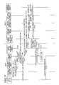
- FIG. 17 is a sequence diagram illustrating procedures of authenticating a user Q and executing a device cooperation job performed by the MFP 1 and the MFP 2.
- the procedures up to step S120 are the same as those of FIGS. 16A and 16B .
- the authentication module 18 of the MFP 2 authenticates the user Q (step S90).
- the authentication module 18 sends an authentication result indicating authentication NG to the job management module 17 of the MFP 1 (steps S100 through S120).
- the job management module 17 of the MFP 1 cancels the job (step S121). Furthermore, the job management module 17 displays an error message on the display unit (step S122). An example of this message is "The cooperating device was unable to authenticate the user. The job will be cancelled.” The user Q views the error message, and may take other measures such as selecting another device (MFP 3) or executing the job only with the MFP 1.
- the user that cannot be authenticated by the MFP 2 is prohibited from using the MFP 2, and therefore the usage amount can be accurately limited.
- the MFP 2 cannot authenticate the user Q, it is assumed that the MFP 2 is not supposed to print the allocated page number allocated to the user Q. However, the MFP 1 can count the usage amount, and therefore there is no problem in the MFP 1 executing the job. Furthermore, if the user Q can set whether to execute a job at the MFP 1, convenience is enhanced. Accordingly, a description is given of a device cooperation system, in which the MFP 1 asks the user Q of the measure to be taken, when the MFP 2 cannot authenticate the user Q.
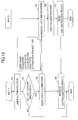
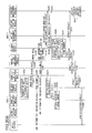
- FIGS. 18A and 18B illustrate a sequence diagram illustrating procedures of authenticating a user Q and executing a device cooperation job performed by the MFP 1 and the MFP 2.
- the procedures up to step S120 are the same as those of FIGS. 16A and 16B .
- the authentication is unsuccessful, and therefore the job management module 17 of the MFP 1 displays an error message on the display unit (step S123).
- the message is, for example, "The cooperating device cannot authenticate the user. Cancel job? Please select YES or NO.”
- the job management module 17 cancels the job as described with reference to FIG. 17 .
- the job management module 17 displays the following message, for example.
- the job management module 17 cancels the job as described with reference to FIG. 17 .
- the job management module 17 executes the job with a single MFP.
- the usage amount determining unit 32 of the job management module 17 collaborates with the resource management module 14 and the engine management module 16 to print the total number of pages (step S240-2).
- the job management module 17 reports the print results in units of output to the counter management module 19 (step S241).
- the counter management module 19 updates the possible usage amount of the MFP 1 in units of output (step S242).
- the job management module 17 of the MFP 1 waits for the printing of the device itself to end, and sends the job execution result to the copy application (step S350).
- the MFP 2 when the MFP 2 cannot authenticate a user, the MFP 2 cannot execute the job, and therefore the usage amount can be accurately limited. Furthermore, the user can print the total number of pages with the MFP 1, and therefore the convenience is prevented from deteriorating.
- the MFP 2 cannot authenticate the user Q, the MFP 2 cannot print the allocated page number allocated to the user Q, but there may be a finishing process that is only effective in the MFP 2. In this case, it would be convenient if the user Q can use the MFP 2. Meanwhile, if the MFP 2 performs the printing, the MFP 2 has not authenticated the user Q, and therefore the printed pages cannot be subtracted from the possible usage amount. Accordingly, a description is given of a device cooperation system, in which when the MFP 2 cannot authenticate the user Q, the MFP 1 and 2 execute the device cooperation job, but the MFP 1 subtracts the usage amount of the MFP 1 and the MFP 2 from the possible usage amount of the MFP 1.
- FIGS. 19A and 19B illustrate a sequence diagram illustrating procedures of authenticating a user Q and executing a device cooperation job performed by the MFP 1 and the MFP 2.
- the procedures up to step S120 are the same as those of FIGS. 16A and 16B .
- the authentication module 18 of the MFP 2 authenticates the user Q (step S90).
- the authentication module 18 sends an authentication result indicating authentication NG to the job management module 17 of the MFP 1 (step S100 through S120).
- the job management module 17 of the MFP 1 requests printing of the allocated page number allocated to the MFP 2 without limiting the usage amount, and subtracts the total number of printed pages from the possible usage amount of the MFP 1.
- the job management module 17 requests the communication management module 15 to acquire the device management information 21 from the MFP 2 (step S130).
- the communication management module 15 requests the communication management module 15 of the MFP 2 to send the device management information 21 (step S140).
- the communication management module 15 of the MFP 2 requests the resource management module 14 to provide the device management information 21 (step S150).
- the resource management module 14 is not shown in FIGS. 16A and 16B .
- the resource management module 14 reads the device management information 21 and sends the device management information 21 to the communication management module 15 (step S160).
- the communication management module 15 of the MFP 2 sends the device management information 21 to the communication management module 15 of the MFP 1 (step S170).
- the communication management module 15 of the MFP 1 sends the device management information 21 of the MFP 2 to the job management module 17 (step S180).
- the allocated number determining unit 31 of the job management module 17 determines the allocated page number for the MFP 2 from the device management information 21 of the MFP 1 and the MFP 2 (step S190). Details are given above and are thus not further described.
- the usage amount determining unit 32 of the job management module 17 determines whether the total number of pages is less than or equal to the possible usage amount of the MFP 1 (step S202).
- the job management module 17 requests the communication management module 15 to send image data (S210).
- the communication management module 15 sends the image data to the communication management module 15 of the MFP 2 (step S220).
- the communication management module 15 of the MFP 2 sends the image data to the job management module 17 (step S230).
- the job management module 17 displays an error message on the display unit, and asks the user whether to perform printing partway or to cancel the job.
- the job management module 17 of the MFP 1 collaborates with the resource management module 14 and the engine management module 16 to print the allocated page number (step S240).
- the job management module 17 reports the print results in units of output to the counter management module 19 (step S241).
- the counter management module 19 updates the usage amount of the MFP 1 in units of output (step S242).
- the job management module 17 of the MFP 1 requests the communication management module 15 to send job information of the output process among all the job information, including the allocated page number of the MFP 2 (step S250).
- the job information includes an instruction prohibiting the subtraction of the usage amount.
- the communication management module 15 sends the job information to the communication management module 15 of the MFP 2 (step S260).
- the communication management module 15 of the MFP 2 sends the job information to the job management module 17 (step S270).
- the job management module 17 of the MFP 2 does not need to read the usage amount limit information, or to determine whether the allocated page number allocated to the MFP 2 is less than or equal to the possible usage amount of the MFP 2.
- the job management module 17 of the MFP 2 collaborates with the resource management module 14 and the engine management module 16 to print the allocated page number (step S310).
- the job management module 17 of the MFP 2 sends the print execution result to the communication management module 15 (step S320).
- the communication management module 15 sends the print execution result to the communication management module 15 of the MFP 1 (step S330).
- the communication management module 15 of the MFP 1 sends the print execution result to the job management module 17 (step S340).
- the job management module 17 reports the execution result of the MFP 2 to the counter management module 19 (step S341), and the counter management module 19 collectively updates the possible usage amount of the MFP 2 (step S342).
- the job management module 17 of the MFP 1 waits for the printing of the device itself to end, and sends the job execution result to the copy application (step S350).
- the MFP 1 collectively manages the usage amounts of the device cooperation system, and therefore even if the MFP 2 cannot authenticate the user, the MFP 1 and the MFP 2 can execute the device cooperation job.
- each MFP manages the possible usage amount for a guest.
- the possible usage amount of a guest is set so that a user can use the MFP during a business trip, for example.
- the MFP 2 cannot authenticate the user Q, by using this possible usage amount of a guest, the MFP 2 can print the allocated page number. Accordingly, a description is given of a device cooperation system, in which the usage amount is subtracted from the possible usage amount for a guest.
- FIGS. 20A and 20B illustrate a sequence diagram illustrating procedures of authenticating a user Q and executing a device cooperation job performed by the MFP 1 and the MFP 2.
- the procedures up to step S120 are the same as those of FIGS. 16A and 16B .
- the authentication module 18 of the MFP 2 authenticates the user Q (step S90).
- the authentication module 18 sends an authentication result indicating authentication NG to the job management module 17 of the MFP 1 (step S100 through S120).
- the job management module 17 of the MFP 1 requests the MFP 2 to print the allocated page number within the possible usage amount for a guest. Therefore, the subsequent process is the same as that of FIGS. 16A and 16B , except that the target of subtraction is the possible usage amount for a guest, instead of the possible usage amount of the MFP 2.
- step S280 the job management module 17 of the MFP 2 requests the counter management module 19 to acquire the usage amount limit information 20 for a guest (step S280).
- the counter management module 19 reads the possible usage amount for a guest from the usage amount limit information 20, and sends the possible usage amount to the job management module 17 (step S290).
- the usage amount determining unit 32 of the job management module 17 of the MFP 2 determines whether the allocated page number allocated to the MFP 2 is less than or equal to the possible usage amount for the guest (step S300).
- the job management module 17 collaborates with the resource management module 14 and the engine management module 16 to print the allocated page number (step S310).
- the job management module 17 of the MFP 2 reports the print results in units of output to the counter management module 19 (step S311).
- the counter management module 19 updates the usage amount for the guest in units of output (step S312).
- the job management module 17 of the MFP 2 sends the print execution result to the communication management module 15 (step S320).
- the communication management module 15 sends the print execution result to the communication management module 15 of the MFP 1 (step S330).
- the communication management module 15 of the MFP 1 sends the print execution result to the job management module 17 (step S340).
- the job management module 17 of the MFP 1 waits for the printing of the device itself to end, and sends the job execution result to the copy application (step S350).
- the MFP 1 and the MFP 2 can execute the device cooperation job within the possible usage amount for the guest.
- a device cooperation system and a function providing method are provided, by which the usage amount of a user can be limited when device cooperation is performed, even when there is no server used for authentication.
Landscapes
- Engineering & Computer Science (AREA)
- Multimedia (AREA)
- Signal Processing (AREA)
- General Engineering & Computer Science (AREA)
- Physics & Mathematics (AREA)
- General Physics & Mathematics (AREA)
- Theoretical Computer Science (AREA)
- Facsimiles In General (AREA)
- Accessory Devices And Overall Control Thereof (AREA)
- Stored Programmes (AREA)
Applications Claiming Priority (1)
| Application Number | Priority Date | Filing Date | Title |
|---|---|---|---|
| JP2011194974A JP5811711B2 (ja) | 2011-09-07 | 2011-09-07 | 機器連携システム、機能提供方法 |
Publications (2)
| Publication Number | Publication Date |
|---|---|
| EP2651111A2 true EP2651111A2 (de) | 2013-10-16 |
| EP2651111A3 EP2651111A3 (de) | 2014-03-19 |
Family
ID=47177726
Family Applications (1)
| Application Number | Title | Priority Date | Filing Date |
|---|---|---|---|
| EP12183088.9A Ceased EP2651111A3 (de) | 2011-09-07 | 2012-09-05 | Vorrichtungskooperationssystem, Funktion mit Bereitstellung eines Verfahrens |
Country Status (5)
| Country | Link |
|---|---|
| US (1) | US8891102B2 (de) |
| EP (1) | EP2651111A3 (de) |
| JP (1) | JP5811711B2 (de) |
| CN (1) | CN103002177B (de) |
| BR (1) | BR102012022625A2 (de) |
Families Citing this family (15)
| Publication number | Priority date | Publication date | Assignee | Title |
|---|---|---|---|---|
| JP6123472B2 (ja) * | 2013-05-13 | 2017-05-10 | 株式会社リコー | 機器管理装置、機器管理システム、機器管理方法及びプログラム |
| JP2015013405A (ja) * | 2013-07-04 | 2015-01-22 | キヤノン株式会社 | 画像形成システム、画像形成装置、画像形成装置の連係方法、及び通信システム |
| WO2015016336A1 (en) | 2013-07-31 | 2015-02-05 | Canon Kabushiki Kaisha | Toner |
| CN103618844A (zh) * | 2013-10-16 | 2014-03-05 | 艾塔斯科技(镇江)有限公司 | 一种扫描仪及其打印系统和控制打印的方法 |
| KR20150138797A (ko) * | 2014-06-02 | 2015-12-10 | 삼성전자주식회사 | 화상형성장치 및 화상 형성 방법 |
| JP6409485B2 (ja) | 2014-10-14 | 2018-10-24 | 株式会社リコー | 画像処理装置、情報処理システム、プログラム、情報処理方法 |
| JP6067648B2 (ja) * | 2014-11-08 | 2017-01-25 | 京セラドキュメントソリューションズ株式会社 | プルプリントシステム |
| US9436417B1 (en) * | 2015-03-16 | 2016-09-06 | Kabushiki Kaisha Toshiba | Printing system capable of printing in any one of plural image forming apparatuses over network, image forming apparatus, and printing method |
| JP2017004133A (ja) * | 2015-06-08 | 2017-01-05 | 株式会社リコー | サービス提供システム、情報処理システム、情報処理装置、サービス提供方法、及びプログラム |
| JP6658118B2 (ja) * | 2016-03-08 | 2020-03-04 | 富士ゼロックス株式会社 | データ処理装置、システム及びプログラム |
| JP6090511B1 (ja) * | 2016-05-06 | 2017-03-08 | 富士ゼロックス株式会社 | 端末装置及びプログラム |
| JP6493466B2 (ja) | 2017-07-28 | 2019-04-03 | 富士ゼロックス株式会社 | 情報処理装置及びプログラム |
| JP6958069B2 (ja) | 2017-07-28 | 2021-11-02 | 富士フイルムビジネスイノベーション株式会社 | 情報処理装置及びプログラム |
| JP6972738B2 (ja) | 2017-07-28 | 2021-11-24 | 富士フイルムビジネスイノベーション株式会社 | 情報処理装置及びプログラム |
| JP6926813B2 (ja) | 2017-08-15 | 2021-08-25 | 富士フイルムビジネスイノベーション株式会社 | 情報処理装置及びプログラム |
Citations (4)
| Publication number | Priority date | Publication date | Assignee | Title |
|---|---|---|---|---|
| US20090059287A1 (en) * | 2007-08-31 | 2009-03-05 | Canon Kabushiki Kaisha | Image processing system and control method therefor |
| US20090086264A1 (en) * | 2007-10-01 | 2009-04-02 | Tomoya Yoshida | Printing system, printer, administrating device for the number of sheets, and program |
| JP2010074431A (ja) | 2008-09-17 | 2010-04-02 | Ricoh Co Ltd | 外部認証を用いた認証機能連携機器、認証機能連携システム及び認証機能連携プログラム |
| JP2011194974A (ja) | 2010-03-18 | 2011-10-06 | Mitsubishi Heavy Ind Ltd | 空力係数推定装置及びこれを用いた舵面故障・損傷検出装置 |
Family Cites Families (12)
| Publication number | Priority date | Publication date | Assignee | Title |
|---|---|---|---|---|
| JP3531776B2 (ja) * | 1996-10-07 | 2004-05-31 | 株式会社リコー | 画像形成システム |
| JP3448186B2 (ja) * | 1997-05-30 | 2003-09-16 | シャープ株式会社 | 画像形成システム |
| JP2001169032A (ja) | 1999-09-30 | 2001-06-22 | Ricoh Co Ltd | デジタル複写機、画像形成システム、およびデジタル複写機のスレーブ機 |
| JP4416264B2 (ja) * | 2000-03-31 | 2010-02-17 | キヤノン株式会社 | 画像処理システム、画像処理システムの制御方法、画像処理装置及び記憶媒体 |
| JP2003108344A (ja) * | 2001-09-28 | 2003-04-11 | Canon Inc | 診断装置及び診断システム及び診断方法及びプログラム並びに媒体 |
| JP4390287B2 (ja) * | 2006-02-08 | 2009-12-24 | キヤノン株式会社 | 印刷システム、及び、印刷装置及びその制御方法 |
| JP2008059150A (ja) | 2006-08-30 | 2008-03-13 | Fuji Xerox Co Ltd | 情報処理プログラム、画像読取プログラム、情報処理装置、画像読取装置および情報処理システム |
| JP2008186109A (ja) | 2007-01-29 | 2008-08-14 | Brother Ind Ltd | 印刷制御システム、印刷装置、認証装置、印刷装置プログラム及び認証装置プログラム |
| CN101901125B (zh) | 2007-04-20 | 2012-05-30 | 夏普株式会社 | 打印控制装置及打印装置 |
| JP5272602B2 (ja) | 2008-09-16 | 2013-08-28 | 株式会社リコー | 認証機能連携機器、認証機能連携システム及び認証機能連携プログラム |
| JP2010198364A (ja) * | 2009-02-25 | 2010-09-09 | Ricoh Co Ltd | 画像形成装置、配信処理システム、画像処理方法、プログラム及び記録媒体 |
| JP4801759B2 (ja) | 2009-06-30 | 2011-10-26 | シャープ株式会社 | 複合機、認証サーバ、及びシステム |
-
2011
- 2011-09-07 JP JP2011194974A patent/JP5811711B2/ja not_active Expired - Fee Related
-
2012
- 2012-09-05 EP EP12183088.9A patent/EP2651111A3/de not_active Ceased
- 2012-09-05 US US13/604,475 patent/US8891102B2/en not_active Expired - Fee Related
- 2012-09-06 BR BRBR102012022625-1A patent/BR102012022625A2/pt not_active Application Discontinuation
- 2012-09-06 CN CN201210327664.XA patent/CN103002177B/zh not_active Expired - Fee Related
Patent Citations (4)
| Publication number | Priority date | Publication date | Assignee | Title |
|---|---|---|---|---|
| US20090059287A1 (en) * | 2007-08-31 | 2009-03-05 | Canon Kabushiki Kaisha | Image processing system and control method therefor |
| US20090086264A1 (en) * | 2007-10-01 | 2009-04-02 | Tomoya Yoshida | Printing system, printer, administrating device for the number of sheets, and program |
| JP2010074431A (ja) | 2008-09-17 | 2010-04-02 | Ricoh Co Ltd | 外部認証を用いた認証機能連携機器、認証機能連携システム及び認証機能連携プログラム |
| JP2011194974A (ja) | 2010-03-18 | 2011-10-06 | Mitsubishi Heavy Ind Ltd | 空力係数推定装置及びこれを用いた舵面故障・損傷検出装置 |
Also Published As
| Publication number | Publication date |
|---|---|
| JP5811711B2 (ja) | 2015-11-11 |
| CN103002177A (zh) | 2013-03-27 |
| US20130057900A1 (en) | 2013-03-07 |
| EP2651111A3 (de) | 2014-03-19 |
| BR102012022625A2 (pt) | 2014-06-17 |
| JP2013058837A (ja) | 2013-03-28 |
| US8891102B2 (en) | 2014-11-18 |
| CN103002177B (zh) | 2015-04-15 |
Similar Documents
| Publication | Publication Date | Title |
|---|---|---|
| US8891102B2 (en) | Device cooperation system, function providing method | |
| US9081615B2 (en) | Device cooperation system, image forming apparatus, and function providing method | |
| US8760702B2 (en) | Device cooperation system, image forming apparatus, function providing method | |
| JP4838985B2 (ja) | 情報処理装置、情報処理方法、情報処理プログラム、及び記録媒体 | |
| JP5811712B2 (ja) | 機器連携システム、画像形成装置、機能提供方法 | |
| JP6149908B2 (ja) | 機器連携システム、機能提供方法 | |
| RU2421778C2 (ru) | Сервер управления печатью, способ управления печатью, программа и носитель записи | |
| JP4697263B2 (ja) | 情報処理装置 | |
| JP5505657B2 (ja) | ジョブ設定登録装置および画像処理装置 | |
| CN100380310C (zh) | 图像形成设备及其控制方法、图像形成系统 | |
| RU2413381C2 (ru) | Система обработки изображения, устройство обработки изображения и способ управления им | |
| US8837005B2 (en) | Data transmission apparatus, control method therefor, and storage medium | |
| JP4650519B2 (ja) | 文書処理装置、画像形成装置、印刷指示装置、画像形成システムおよびプログラム | |
| US20160021262A1 (en) | Image forming apparatus, controlling method of image forming apparatus and storage medium | |
| KR20100105418A (ko) | 정보 처리 장치 및 그 제어 방법 | |
| JP4523882B2 (ja) | 画像形成装置と画像形成装置の管理方法 | |
| JP6090404B2 (ja) | 機器連携システム、画像形成装置、サービス提供方法 | |
| JP2013056515A (ja) | 利用量制限装置、機器システム、プログラム | |
| JP2011035779A (ja) | 画像処理システム、画像処理装置及び画像形成装置 | |
| JP6089621B2 (ja) | 操作端末、操作端末を用いた情報処理システム、情報処理方法、プログラム | |
| JP4598145B2 (ja) | 情報処理装置、情報処理方法、情報処理プログラム、及び記録媒体 | |
| JP4398795B2 (ja) | 情報処理装置、情報処理方法、情報処理プログラム、及び記録媒体 | |
| JP2011192116A (ja) | 画像形成システムおよびユーザマネージャサーバ装置 |
Legal Events
| Date | Code | Title | Description |
|---|---|---|---|
| PUAI | Public reference made under article 153(3) epc to a published international application that has entered the european phase |
Free format text: ORIGINAL CODE: 0009012 |
|
| 17P | Request for examination filed |
Effective date: 20120905 |
|
| AK | Designated contracting states |
Kind code of ref document: A2 Designated state(s): AL AT BE BG CH CY CZ DE DK EE ES FI FR GB GR HR HU IE IS IT LI LT LU LV MC MK MT NL NO PL PT RO RS SE SI SK SM TR |
|
| AX | Request for extension of the european patent |
Extension state: BA ME |
|
| PUAL | Search report despatched |
Free format text: ORIGINAL CODE: 0009013 |
|
| AK | Designated contracting states |
Kind code of ref document: A3 Designated state(s): AL AT BE BG CH CY CZ DE DK EE ES FI FR GB GR HR HU IE IS IT LI LT LU LV MC MK MT NL NO PL PT RO RS SE SI SK SM TR |
|
| AX | Request for extension of the european patent |
Extension state: BA ME |
|
| RIC1 | Information provided on ipc code assigned before grant |
Ipc: H04N 1/32 20060101AFI20140211BHEP Ipc: H04N 1/00 20060101ALI20140211BHEP Ipc: H04N 1/44 20060101ALI20140211BHEP Ipc: G06K 15/00 20060101ALI20140211BHEP |
|
| 17Q | First examination report despatched |
Effective date: 20141111 |
|
| STAA | Information on the status of an ep patent application or granted ep patent |
Free format text: STATUS: THE APPLICATION HAS BEEN REFUSED |
|
| 18R | Application refused |
Effective date: 20171108 |