EP2651321B1 - Dispositif pour effectuer une craniotomie décompressive - Google Patents
Dispositif pour effectuer une craniotomie décompressive Download PDFInfo
- Publication number
- EP2651321B1 EP2651321B1 EP11849131.5A EP11849131A EP2651321B1 EP 2651321 B1 EP2651321 B1 EP 2651321B1 EP 11849131 A EP11849131 A EP 11849131A EP 2651321 B1 EP2651321 B1 EP 2651321B1
- Authority
- EP
- European Patent Office
- Prior art keywords
- skull
- bone
- fixation device
- cranial
- bone flap
- Prior art date
- Legal status (The legal status is an assumption and is not a legal conclusion. Google has not performed a legal analysis and makes no representation as to the accuracy of the status listed.)
- Active
Links
Images


Classifications
-
- A—HUMAN NECESSITIES
- A61—MEDICAL OR VETERINARY SCIENCE; HYGIENE
- A61L—METHODS OR APPARATUS FOR STERILISING MATERIALS OR OBJECTS IN GENERAL; DISINFECTION, STERILISATION OR DEODORISATION OF AIR; CHEMICAL ASPECTS OF BANDAGES, DRESSINGS, ABSORBENT PADS OR SURGICAL ARTICLES; MATERIALS FOR BANDAGES, DRESSINGS, ABSORBENT PADS OR SURGICAL ARTICLES
- A61L31/00—Materials for other surgical articles, e.g. stents, stent-grafts, shunts, surgical drapes, guide wires, materials for adhesion prevention, occluding devices, surgical gloves, tissue fixation devices
- A61L31/02—Inorganic materials
- A61L31/022—Metals or alloys
-
- A—HUMAN NECESSITIES
- A61—MEDICAL OR VETERINARY SCIENCE; HYGIENE
- A61B—DIAGNOSIS; SURGERY; IDENTIFICATION
- A61B17/00—Surgical instruments, devices or methods
- A61B17/56—Surgical instruments or methods for treatment of bones or joints; Devices specially adapted therefor
- A61B17/58—Surgical instruments or methods for treatment of bones or joints; Devices specially adapted therefor for osteosynthesis, e.g. bone plates, screws or setting implements
- A61B17/68—Internal fixation devices, including fasteners and spinal fixators, even if a part thereof projects from the skin
- A61B17/80—Cortical plates, i.e. bone plates; Instruments for holding or positioning cortical plates, or for compressing bones attached to cortical plates
-
- A—HUMAN NECESSITIES
- A61—MEDICAL OR VETERINARY SCIENCE; HYGIENE
- A61B—DIAGNOSIS; SURGERY; IDENTIFICATION
- A61B17/00—Surgical instruments, devices or methods
- A61B17/56—Surgical instruments or methods for treatment of bones or joints; Devices specially adapted therefor
- A61B17/58—Surgical instruments or methods for treatment of bones or joints; Devices specially adapted therefor for osteosynthesis, e.g. bone plates, screws or setting implements
- A61B17/68—Internal fixation devices, including fasteners and spinal fixators, even if a part thereof projects from the skin
- A61B17/688—Internal fixation devices, including fasteners and spinal fixators, even if a part thereof projects from the skin for reattaching pieces of the skull
-
- A—HUMAN NECESSITIES
- A61—MEDICAL OR VETERINARY SCIENCE; HYGIENE
- A61B—DIAGNOSIS; SURGERY; IDENTIFICATION
- A61B17/00—Surgical instruments, devices or methods
- A61B17/56—Surgical instruments or methods for treatment of bones or joints; Devices specially adapted therefor
- A61B17/58—Surgical instruments or methods for treatment of bones or joints; Devices specially adapted therefor for osteosynthesis, e.g. bone plates, screws or setting implements
- A61B17/68—Internal fixation devices, including fasteners and spinal fixators, even if a part thereof projects from the skin
- A61B17/80—Cortical plates, i.e. bone plates; Instruments for holding or positioning cortical plates, or for compressing bones attached to cortical plates
- A61B17/8004—Cortical plates, i.e. bone plates; Instruments for holding or positioning cortical plates, or for compressing bones attached to cortical plates with means for distracting or compressing the bone or bones
-
- A—HUMAN NECESSITIES
- A61—MEDICAL OR VETERINARY SCIENCE; HYGIENE
- A61B—DIAGNOSIS; SURGERY; IDENTIFICATION
- A61B17/00—Surgical instruments, devices or methods
- A61B17/56—Surgical instruments or methods for treatment of bones or joints; Devices specially adapted therefor
- A61B17/58—Surgical instruments or methods for treatment of bones or joints; Devices specially adapted therefor for osteosynthesis, e.g. bone plates, screws or setting implements
- A61B17/68—Internal fixation devices, including fasteners and spinal fixators, even if a part thereof projects from the skin
- A61B17/80—Cortical plates, i.e. bone plates; Instruments for holding or positioning cortical plates, or for compressing bones attached to cortical plates
- A61B17/8061—Cortical plates, i.e. bone plates; Instruments for holding or positioning cortical plates, or for compressing bones attached to cortical plates specially adapted for particular bones
-
- A—HUMAN NECESSITIES
- A61—MEDICAL OR VETERINARY SCIENCE; HYGIENE
- A61B—DIAGNOSIS; SURGERY; IDENTIFICATION
- A61B17/00—Surgical instruments, devices or methods
- A61B17/56—Surgical instruments or methods for treatment of bones or joints; Devices specially adapted therefor
- A61B17/58—Surgical instruments or methods for treatment of bones or joints; Devices specially adapted therefor for osteosynthesis, e.g. bone plates, screws or setting implements
- A61B17/68—Internal fixation devices, including fasteners and spinal fixators, even if a part thereof projects from the skin
- A61B17/82—Internal fixation devices, including fasteners and spinal fixators, even if a part thereof projects from the skin for bone cerclage
-
- A—HUMAN NECESSITIES
- A61—MEDICAL OR VETERINARY SCIENCE; HYGIENE
- A61B—DIAGNOSIS; SURGERY; IDENTIFICATION
- A61B17/00—Surgical instruments, devices or methods
- A61B17/56—Surgical instruments or methods for treatment of bones or joints; Devices specially adapted therefor
- A61B17/58—Surgical instruments or methods for treatment of bones or joints; Devices specially adapted therefor for osteosynthesis, e.g. bone plates, screws or setting implements
- A61B17/68—Internal fixation devices, including fasteners and spinal fixators, even if a part thereof projects from the skin
- A61B17/84—Fasteners therefor or fasteners being internal fixation devices
- A61B17/86—Pins or screws or threaded wires; nuts therefor
-
- A—HUMAN NECESSITIES
- A61—MEDICAL OR VETERINARY SCIENCE; HYGIENE
- A61L—METHODS OR APPARATUS FOR STERILISING MATERIALS OR OBJECTS IN GENERAL; DISINFECTION, STERILISATION OR DEODORISATION OF AIR; CHEMICAL ASPECTS OF BANDAGES, DRESSINGS, ABSORBENT PADS OR SURGICAL ARTICLES; MATERIALS FOR BANDAGES, DRESSINGS, ABSORBENT PADS OR SURGICAL ARTICLES
- A61L27/00—Materials for grafts or prostheses or for coating grafts or prostheses
- A61L27/50—Materials characterised by their function or physical properties, e.g. injectable or lubricating compositions, shape-memory materials, surface modified materials
- A61L27/58—Materials at least partially resorbable by the body
-
- A—HUMAN NECESSITIES
- A61—MEDICAL OR VETERINARY SCIENCE; HYGIENE
- A61L—METHODS OR APPARATUS FOR STERILISING MATERIALS OR OBJECTS IN GENERAL; DISINFECTION, STERILISATION OR DEODORISATION OF AIR; CHEMICAL ASPECTS OF BANDAGES, DRESSINGS, ABSORBENT PADS OR SURGICAL ARTICLES; MATERIALS FOR BANDAGES, DRESSINGS, ABSORBENT PADS OR SURGICAL ARTICLES
- A61L31/00—Materials for other surgical articles, e.g. stents, stent-grafts, shunts, surgical drapes, guide wires, materials for adhesion prevention, occluding devices, surgical gloves, tissue fixation devices
- A61L31/04—Macromolecular materials
-
- A—HUMAN NECESSITIES
- A61—MEDICAL OR VETERINARY SCIENCE; HYGIENE
- A61B—DIAGNOSIS; SURGERY; IDENTIFICATION
- A61B17/00—Surgical instruments, devices or methods
- A61B2017/00004—(bio)absorbable, (bio)resorbable or resorptive
-
- A—HUMAN NECESSITIES
- A61—MEDICAL OR VETERINARY SCIENCE; HYGIENE
- A61B—DIAGNOSIS; SURGERY; IDENTIFICATION
- A61B17/00—Surgical instruments, devices or methods
- A61B2017/00831—Material properties
- A61B2017/00862—Material properties elastic or resilient
Definitions
- the invention relates to a device for performing a decompressive craniotomy.
- Neurosurgery routinely involves performing craniotomies for exposure of the brain and intracranial contents for various intracranial pathologies including, but not limited to, tumors, head injuries, vascular malformations, aneurysms, infections, hemorrhages, strokes, and brain swelling.
- a craniotomy typically involves the creation of burr holes and the removal of a portion of the skull (i.e., bone flap) with subsequent healing of the bone flap for closure.
- an aspect of the prior art generally useful to be aware of is that several methods and fixation devices are currently available for re-attaching the bone flap to the skull including small metallic or absorbable plates with screws or wires.
- Another current method is the use of cranial clamps consisting of two connected circular elements placed on the inside and outside surfaces of the skull.
- the aforementioned cranial fixation devices generally provide for a rigid fixation of the bone flap to the skull.
- a decompressive craniectomy is a neurosurgical procedure generally used to treat increased pressure within the skull, herein referred to as intracranial pressure (ICP), from causes such as, but not limited to, head injury, stroke, brain tumor, infection, cerebral hemorrhage, space occupying lesions, hypoxia, hypertension, aneurysm, arteriovenous malformation, venous sinus thrombosis, craniosynostosis, and hydrocephalus.
- ICP intracranial pressure
- the technique of performing a decompressive craniectomy often involves the removal of a portion of the skull and opening of the dura mater covering the brain, thereby allowing the swollen brain to herniate outwards through the surgical skull defect rather than downwards to compress the brainstem.
- the procedure generally improves outcomes by lowering ICP.
- Increased ICP is often debilitating or fatal because this pressure may result in compression of the brain and restriction of cerebral blood flow.
- a typical aim of a decompressive craniectomy is to reduce this pressure. In general, it is believed that the larger the bone flap, the more ICP is reduced.
- the dural opening is typically closed with a patch graft taken from a cow, pig, cadaver, or a synthetic graft.
- a synthetic collagen matrix is often used as a graft since the matrix is capable of expanding.
- a decompressive craniectomy may improve cerebral perfusion pressure and cerebral blood flow in patients with head injuries.
- a decompressive craniectomy may also be used in some cases to treat major strokes associated with malignant brain swelling and increased ICP. It is believed that a decompressive craniectomy typically improves survival and functional outcome in patients with severe brain swelling from causes such as, but not limited to, head injury or stroke if performed in a timely manner. There usually is an inherent time delay between diagnosing the cause of the increased ICP and performing a decompressive craniectomy.
- a craniectomy After a craniectomy, it is believed that the risk of brain injury is increased because of the removed bone flap, particularly after the patient heals and becomes mobile again. In addition, there is often an obvious cosmetic skin deformity. Therefore, special measures are generally taken to protect the brain, such as, but not limited to, a helmet or a temporary implant in the skull. Other risks that may arise out of a craniectomy include, without limitation, infection, cerebrospinal fluid leakage, hydrocephalus, encephalomyocele, subdural hygroma and hemorrhage.
- a cranioplasty typically involves the repair of a defect in the vault of the skull. This repair may be carried out by using bone removed in an earlier surgery that has been preserved or by using bone from elsewhere as a graft. Bone that may be used as a graft may include, without limitation, the iliac bone bounding the pelvis, ribs or a portion of adjacent skull bone. If possible, the original bone flap is generally preserved after the craniectomy in anticipation of the cranioplasty. The bone flap is usually stored sterilely in a freezer until the patient is ready for implantation of the bone flap into the craniectomy skull defect.
- this time period can last several months since it may take this long to treat the underlying cause of the increased ICP.
- This extended time period may result in the increased risk of brain injury and may also cause an increased risk of infection in the stored bone flap.
- Another technique of storing a removed bone flap typically involves placing the bone flap under the skin in the abdomen of the patient. This technique generally requires a surgical procedure to place the bone flap in the abdomen and another surgical procedure to remove the bone flap, thereby typically increasing consequent risks to the patient.
- the skull defect is generally repaired with a prosthetic plate or titanium mesh and bone cement.
- a prosthetic plate typically cannot completely replicate the original skull defect, and therefore some cosmetic deformity often persists following a prosthetic cranioplasty.
- the prosthesis may also increase the risk of infection.
- the risks associated with cranioplasty typically include, without limitation, infection, hemorrhage, brain injury, seizures, and death along with other risks inherent to any surgery and general anesthesia. It is also usually necessary for the patient to remain in the hospital for a week or so after a cranioplasty.
- Distraction osteogenesis is a surgical process used to reconstruct craniofacial deformities.
- the bone is fractured into two segments, and the two bone ends of the bone are gradually moved apart during the distraction phase, allowing new bone to form in the gap and reshape the length of the bone.
- a consolidation phase follows in which the bone is allowed to solidify in the gap.
- one such device describes a telescopic bone plate for use in bone lengthening by distraction osteogenesis.
- the bone plate is attached to osteomically separated mandible or skull sections by a thread screw assembly.
- the extent of the required distraction can be adjusted by an external screwdriver.
- Another such device describes a skull fixation device typically used for the treatment of craniofacial deformities that provides for relative movement of the skull segments by a percutaneously placed external wrench.
- Yet another such device describes a mandible or skull expansion plate. The extent of the expansion is adjusted by an externally placed device.
- Another currently available skull expansion plate comprises a hinged plate at one end and a bone adjuster at the other end comprising two plates with a shaft. The shaft is operated externally to adjust the distance between the bone flap and the skull.
- the aforementioned cranial fixation devices in the prior art provide for treatment of craniofacial defects, in particular craniosynostosis.
- These devices generally require an external screwdriver or other external adjustment means to control the extent of the skull movement allowed and do not typically describe or provide for outward or inward movement of the bone flap relative to the skull in response to a change in the ICP.
- These devices are also generally placed on the outer surface of the skull and have substantially high profiles which may result in increasing the risk of scalp irritation and palpable cosmetic deformities.
- chronic scalp irritation may cause erosion and exposure of the device through the skin with consequent life threatening infections.
- US patent application 2008/0200954 describes cranial fixation devices comprising a first anchor portion configured to join to a skull, a second anchor portion configured to join to a cranial bone portion and an intermediate component extending between said first anchor portion and said second anchor portion, said intermediate component being configured to pivot, bend or translate to enable constrained outward movement of the cranial bone portion relative to the skull with an increase of intracranial pressure and to move the cranial bone portion back towards the skull with a normalization of intracranial pressure.
- One aspect of the prior art generally useful to be aware of is that there are multiple methods for performing a decompressive craniectomy.
- One method of performing a decompressive craniectomy involves attaching the bone flap to the skull with a hinged plate. This method describes attaching the hinged plate to one end of the bone flap and attaching the other end of the bone flap to a rigid plate or no plate at all. The described method typically involves another surgery to fixate the unconstrained bone flap at the rigid plate or plate free end to the skull once the brain swelling subsides.
- Another method describes a deformable plate which may be used instead of a hinged plate as the bone flap attachment. This construct also typically involves another surgery to fixate the unconstrained bone flap at the straight plate or plate free end of the bone flap.
- the end of the bone flap attached to the hinged or deformable plate is generally unable to move outwards, and therefore allows limited bone flap movement.
- Another method involves the use of a two part, sliding device for cranial fixation. This device protrudes outwards from the skull surface and may result in a cosmetic defect, overlying skin irritation, risk of erosion or infection, and typically requires another operation to remove the device once the bone flap heals to the skull.
- references to "one embodiment,” “an embodiment,” “example embodiment,” “various embodiments,” etc., may indicate that the embodiment(s) of the invention so described may include a particular feature, structure, or characteristic, but not every embodiment necessarily includes the particular feature, structure, or characteristic. Further, repeated use of the phrase “in one embodiment,” or “in an exemplary embodiment,” do not necessarily refer to the same embodiment, although they may.
- a practical embodiment of the present invention provides a cranial fixation device for fixing a bone flap to the skull following a craniotomy with immediate treatment of increased ICP that generally avoids the need for performing a subsequent cranioplasty.
- Many practical embodiments provide cranial fixation following a craniotomy with a fixation device that allows for constrained movement of the bone flap to immediately accommodate an increase in ICP and subsequently enables the bone flap to move inward toward the skull once the ICP normalizes.
- this fixation device is a flexible and expandable cranial fixation plate.
- the cranial fixation device comprises spaced anchor portions and an intermediate component extending between the anchor portions which comprises a series of elastic tension spring members allowing for expansion and contraction. Since the decompressive procedure provided in many practical embodiments involves leaving the bone flap in place rather than removing the bone flap as is typically done in a decompressive craniectomy, this procedure is herein referred to as a decompressive craniotomy.
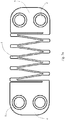
- Figs. 1 through 3 illustrate an exemplary cranial fixation device with a rectangular shape, in accordance with an embodiment of the present invention.
- Fig. 1 is a diagrammatic top view of the device in a contracted position and
- Fig. 3a is a diagrammatic top view in an expanded position.
- Fig. 2 is a perspective top view, and
- Fig. 3 is a diagrammatic side view.
- the device comprises an anchor portion 4 with bone fastener holes 1 for attachment to a skull and an anchor portion 5 with bone fastener holes 2 for attachment to a bone flap.
- An intermediate component 3 comprises a series of elastic tension spring members that expand or contract depending on the ICP and allow outward movement of the bone flap relative to the skull.
- the tension spring members of intermediate component 3 comprise of a series of parallel, elastically deformable metal strips joined at the strip ends.
- the contracted position of intermediate component 3 is illustrated by way of example in Figs. 1 through 3 .
- the swollen brain exerts pressure on the bone flap forcing the elastic tension spring members of intermediate component 3 to expand and allow anchor portion 5 attached to the bone flap to move outward to accommodate the increase in ICP by increasing the skull space.
- the expanded tension spring members of intermediate component 3 contract and return the bone flap to a position substantially even with the skull.
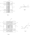
- Figs. 4 through 7 illustrate an exemplary cranial fixation device with a square shape, in accordance with an embodiment of the present invention.
- Fig. 4 is a diagrammatic top view of the device in a contracted position.
- Fig. 5 is a diagrammatic side view of the device in the contracted position.
- Fig. 6 is a diagrammatic top view of the device in an expanded position, and
- Fig. 7 is a diagrammatic side view of the device in an expanded position.
- a skull attachment anchor portion 6 comprises bone fastener holes 8 and 53
- a bone flap attachment anchor portion 7 comprises bone fastener holes 9 and 11.
- Anchor portions 6 and 7 are connected by an intermediate component 10 comprising a series of parallel tension springs which are elastically deformable strips joined together at the ends and the middle portions of the strips. Referring to Fig. 7 , this expanded position of intermediate component 10 allows bone flap anchor portion 7 to move upward relative to skull anchor portion 6.
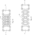
- Figs. 8 through 10 illustrate an exemplary cranial fixation device with a circular shape, in accordance with an embodiment of the present invention.
- Fig. 8 is a diagrammatic top view of the device in a contracted position.
- Fig. 9 is a diagrammatic side view of the device in the contracted position, and
- Fig. 10 is a diagrammatic top view of the device in an expanded position.
- the circular shape of the device may be well suited to cover a burr hole skull defect.
- the device comprises of a first anchor portion 12 with bone fastener holes 14 and a second anchor portion 13 with bone fastener holes 15. Anchor portions 12 and 13 are connected by an intermediate component 16.
- Intermediate component 16 comprises a plurality of parallel tension springs that reversibly expand or contract dependent upon the pressure exerted on the anchor portion attached to the bone flap.
- intermediate component 16 is designed to expand when the ICP exceeds 20 to 25 mm Hg and to retract when the ICP is normal (i.e., less than 15 to 20 mmHg). It is contemplated that some alternate embodiments may be implemented to expand and retract at different pressures in order to accommodate applications in which the ICP may be higher or lower than normal.
- Figs. 11 through 13 illustrate an exemplary cranial fixation device with a circular shape, in accordance with an embodiment of the present invention.
- Fig. 11 is a diagrammatic top view of the device in a contracted position.
- Fig. 12 is a perspective side view of the device in the contracted position attached to a skull 54 on one side and a bone flap 55 on the other side.
- Fig. 13 is a diagrammatic top view of the device in an expanded position.
- the device comprises anchor portions 17 and 18 with bone fastener holes 21 and 22, respectively, separated by a space 25 and anchor portions 19 and 20 with bone fastener holes 23 and 24, respectively, separated by a space 26.
- Anchor portions 17 and 18 are connected with anchor portions 19 and 20 by an intermediate component 27.
- Intermediate component 27 comprises a plurality of tension springs that reversibly expand or contract dependent upon the pressure exerted on one anchor portion versus the other.
- the four anchor portions 17, 18, 19, and 20 can move independently of each other's positions, thereby allowing for a particularly flexible device.
- the configuration of the anchor portions come together to form substantially rectangular, square or circular shapes when in a compressed position.
- anchor portions with a multiplicity of suitable configurations such as, but not limited to, oval configurations, semi-circle configurations, semi-oval configurations, C-shapes, L-shapes, T-shapes, X-shapes, Y-shapes, Z-shapes, fan shapes, configurations in which the anchor portions differ from each other in size and/or shape, or any other configuration able to connect a skull to a bone flap.
- Some alternate embodiments may comprise multiple intermediate components that may or may not be joined to opposite anchor portions.
- the cranial fixation devices described in the foregoing are illustrated by way of example with unitary construction, such that the anchor portions and intermediate components are formed from a single piece material.
- the components of the cranial fixation devices can be non-integral such that the components may be attached to and/or coupled to other components of the device.
- the intermediate components illustrated by way of example in the forgoing comprise substantially parallel tension springs that are connected at the ends or connected at the ends and the middle portions.
- the expandable intermediate component in some alternate embodiments may comprise a multiplicity of suitable expansion means including, without limitation, tension springs attached at the middle only, tension springs with an accordion-like configuration, expandable mesh material, cross-links, compressed O-shaped, U-shaped, V-shaped, X-shaped or W-shaped members that expand, a plurality of cutouts, a single tension spring, an elastomeric component, a spring, hinged connectors, coiled wire, chain, sliding connectors, an elastic cord, or a combination thereof.
- suitable expansion means including, without limitation, tension springs attached at the middle only, tension springs with an accordion-like configuration, expandable mesh material, cross-links, compressed O-shaped, U-shaped, V-shaped, X-shaped or W-shaped members that expand, a plurality of cutouts, a single tension spring, an elastomeric component, a spring, hinged connectors, coiled wire, chain, sliding connectors, an elastic cord, or a combination thereof.
- cranial fixation devices may be made of a multiplicity of suitable materials including, without limitation, metals such as, but not limited to, titanium or titanium alloy for MRI imaging compatibility.
- suitable materials including, without limitation, metals such as, but not limited to, titanium or titanium alloy for MRI imaging compatibility.
- Some embodiments may be made of materials that are typically absorbed by the body over time including, without limitation, allograft, xenograft bone, or a bioresorbable material such as, but not limited to, polyesters, poly amino acids, polyanhydrides, polyorthoesters, polyurethanes, polycarbonates, homopolymers, copolymers of poly lactic acid and poly glycolic acid, copolyesters of e-caprolactone, trimethylene carbonate, or para-dioxanone.
- some embodiments may be made of a radiolucent material such as, but not limited to, polyetheretherketone (PEEK), polyaryletherketone (PEAK), high molecular weight polyethylene, carbon fiber, polyurethane, plastic, or a combination of plastic and metal to reduce CT and MRI imaging artifact.
- the expandable material of the intermediate components in some embodiments may be made of various different materials such as, but not limited to, silicone, rubber, ethylene propylene compounds, flourocarbon, polyurethane, titanium, other metal components designed to reversibly expand and/or contract, etc.
- the thickness of the device generally ranges from 0.3 mm to 20 mm.
- the size of the anchor portions generally range from 6 mm to 40 mm.
- the expandable intermediate component of the cranial fixation device is typically capable of reversibly expanding from 1 to 1000% of its contracted size. While the above-mentioned size ranges of the device components reflect many practical embodiments, some alternate embodiments may comprise components outside of the aforementioned ranges.
- the cranial fixation device comprises anchor portions that are relatively small in size in relation to an expandable intermediate component that connects the anchor portions.
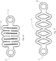
- Figs. 14 and 15 illustrate an exemplary cranial fixation device, in accordance with an embodiment of the present invention.
- Fig. 14 is a diagrammatic top view of the device in a contracted position
- Fig. 15 is a diagrammatic top view of the device in an expanded position.
- the device comprises a first anchor portion 27 with a bone fastener hole and a second anchor portion 28 with a bone fastener hole.
- Anchor portions 27 and 28 are connected by an expandable intermediate component 29.
- Intermediate component 29 comprises a series of compressed, oval-shaped tension springs, as shown by way of example in FIG. 14 , which are capable of reversibly expanding into wider diamond shapes, as shown by way of example in FIG. 15 .
- Figs. 16 and 17 illustrate an exemplary cranial fixation device, in accordance with an embodiment of the present invention.
- Fig. 16 is a diagrammatic top view of the device in a contracted position
- Fig. 17 is a diagrammatic top view of the device in an expanded position.
- the device comprises a first anchor portion 30 with bone screw holes 32 and 33 and a second anchor portion 31 with bone screw holes 34 and 35.
- An intermediate component 36 comprising a series of compressed, oval-shaped tension springs connects anchor portions 30 and 31.
- Figs. 18 and 19 illustrate an exemplary cranial fixation device, in accordance with an embodiment of the present invention.
- Fig. 18 is a diagrammatic top view of the device in a contracted position
- Fig. 19 is a diagrammatic top view of the device in an expanded position.
- anchor portions 37 and 38 each comprise four bone fastener holes and are connected by a series of elastic tension spring members in an intermediate component 39.
- cranial fixation devices similar to the devices illustrated by way of example in Figs. 14 through 19 may comprise more or fewer holes for bone fasteners or bone screws, tension springs of various different shapes, other types of expanding means, etc.
- some alternate embodiments may be implemented in various different configurations such as, but not limited to, rectangular configurations with four anchor portions and four intermediate components, triangular configurations, L-shaped configurations, T-shaped configurations, V-shaped configurations, X-shaped configurations, Z-shaped configurations, etc.
- Figs. 20 and 21 are cross sectional side views of exemplary cranial fixation devices 40 and 47 attached to a skull 43 and a bone flap 41 for a decompressive craniotomy, in accordance with an embodiment of the present invention.
- Fig. 20 shows a brain 45 in a non-swollen state
- Fig. 21 shows brain 45 in a swollen state.
- cranial fixation device 40 is attached to bone flap 41 with a screw 42 and is attached to skull 43 with a screw 44.
- the length of screws 42 and 44 can range from 4 mm to 20 mm.
- the cranial fixation devices may be attached to the skull and bone flap with larger or smaller screws, with spikes, with a combination of screws on one anchor portion and spikes on the other anchor portion, etc.
- the cranial fixation device may comprise various different attachment means such as, but not limited to, clamps which are attached to the skull and/or bone flap, self-tapping screws, self-drilling screws, pins, rivets, wires, sutures, clamps, claws, spikes, hooks, adhesives, etc.
- the fixation devices may be attached to the skull with attachment means and left unattached to the bone flap to provide greater mobility of the bone flap. Referring to Figs.
- cranial fixation devices 40 and 47 typically two or more cranial fixation devices 40 and 47 are used to affix bone flap 41 to skull 43.
- a cranial fixation device can be placed on one side of the bone flap and a hinge device can be placed on the other side to provide a similar yet potentially limited decompressive craniotomy.
- brain 45 and a dura 46 are in a normal position.
- FIG. 21 with the development of swelling of brain 45 or an increase in ICP from a hemorrhage or other cause, brain 45 pushes against bone flap 41.
- the pressure on bone flap 41 expands the intermediate components of cranial fixation devices 40 and 47, thereby allowing the anchor portions attached to bone flap 41 to move outward relative to the anchor portions attached to skull 43 to accommodate the swelling of brain 45.
- cranial fixation devices 40 and 47 draw back to their contracted positions, and bone flap 41 moves back towards skull 43.
- Figs. 22 and 23 are side perspective views of exemplary cranial fixation devices 50, 51 and 52 in place to secure a bone flap 49 to a skull 48 by a decompressive craniotomy, in accordance with an embodiment of the present invention.
- Fig. 22 shows the normal position of bone flap 49
- Fig. 23 shows bone flap 49 shifted outwards relative to skull 48 to accommodate an increase in the pressure inside skull 48.
- a craniotomy bone flap 49 is attached to skull 48 with cranial fixation devices 50, 51, and 52.
- Devices 50, 51 and 52 are spaced apart to provide adequate support and to generally prevent bone flap 49 from sinking below the surface of skull 48.
- Flexible intermediate components of devices 50, 51, and 52 enable bone flap 49 to move outward relative to skull 48 to accommodate an increase in ICP and to retract when any such pressure subsides.
- Normal ICP is typically less than 20 mm Hg, and with any brain swelling or hemorrhage ICP can increase to greater than 20 mm Hg.
- cranial fixation devices 50, 51 and 52 are designed to enable the intermediate components to lengthen into an extended position from a contracted position and therefore enable the two anchor portions of each device 50, 51 and 52 to move apart, thereby allowing bone flap 49 to move outwards from skull 48 in a constrained manner to accommodate the higher ICP.
- the intermediate components retract and position bone flap 49 downwards to substantially the same level as skull 48.
- Fig. 24 is a flowchart illustrating an exemplary method for a decompressive craniotomy.
- a decompressive craniotomy is typically performed to reduce increases in the ICP of a patient, which may be caused by a variety of factors or occurrences.
- the process begins in step 61 by removing a portion of the skull.
- step 63 the dura matter covering the brain is opened, thereby allowing the swollen brain to herniate outwards through the surgical skull defect.
- the larger the bone flap removed in step 61 is, the more ICP is reduced.
- the practitioners may take this opportunity to perform necessary or requested procedures on the brain of the patient in step 65 such as, but not limited to, hematoma evacuation, biopsies, tumor removal, repairing an injury, placing a shunt, etc.
- the dural opening is typically closed in step 67.
- the dural closure material is often a collagen matrix that allows for expansion.
- other dural substitutes may be used such as, but not limited to, grafts made from autograft, allograft, or xenograft material or grafts taken from cows, pigs, cadavers, etc. In an alternate embodiment, this step may be skipped, and the dura may be left open.
- the bone flap is replaced and attached to the skull by one or more expandable cranial fixation devices in step 69.
- expandable cranial fixation devices typically, two more of expandable cranial fixation devices are used to achieve this form of decompressive craniotomy.
- an expandable cranial fixation device can be placed on one side of the bone flap and a hinge device can be placed on the other side.
- the anchor portions of the cranial fixation devices are positioned on the surfaces of the skull and the bone flap to hold the bone flap substantially level with the skull when the expandable intermediate components of the fixation devices are contracted and to allow external movement of the bone flap relative to the skull in case of an increase in ICP.
- the bone flap When an increase in ICP exceeds the normal range, the bone flap is pushed outwards and causes the expandable intermediate components of the cranial fixation devices to stretch into an extended position.
- the external movement of the bone flap increases the intracranial space to accommodate the increase in ICP and provides for a decompressive craniotomy.
- the bone flap Following normalization of the ICP, the bone flap is compressed back towards the skull by the cranial fixation devices.
- cranial fixation devices may be used to treat ICP resulting from various different causes such as, but not limited to, traumatic injury, subdural hemorrhage, epidural hemorrhage, subarachnoid hemorrhage, intra-ventricular hemorrhage, brain hemorrhage, ischemic stroke, hemorrhagic stroke, hypoxia, tumor, infection, brain swelling, or seizure, etc.
- some embodiments may be used in different types of applications including, but not limited to, covering a burr hole, repairing a skull fracture, treating congenital cranial skull defects such as, but not limited to, craniosynostosis, etc.
- any of the foregoing steps may be suitably replaced, reordered, removed and additional steps may be inserted depending upon the needs of the particular application.
- the prescribed method steps may be implemented using any physical and/or hardware system that those skilled in the art will readily know is suitable in light of the foregoing teachings.
- a typical computer system can, when appropriately configured or designed, serve as a computer system.
Landscapes
- Health & Medical Sciences (AREA)
- Orthopedic Medicine & Surgery (AREA)
- Life Sciences & Earth Sciences (AREA)
- Surgery (AREA)
- General Health & Medical Sciences (AREA)
- Veterinary Medicine (AREA)
- Public Health (AREA)
- Animal Behavior & Ethology (AREA)
- Heart & Thoracic Surgery (AREA)
- Molecular Biology (AREA)
- Medical Informatics (AREA)
- Neurology (AREA)
- Nuclear Medicine, Radiotherapy & Molecular Imaging (AREA)
- Engineering & Computer Science (AREA)
- Biomedical Technology (AREA)
- Epidemiology (AREA)
- Vascular Medicine (AREA)
- Chemical & Material Sciences (AREA)
- Inorganic Chemistry (AREA)
- Neurosurgery (AREA)
- Dermatology (AREA)
- Medicinal Chemistry (AREA)
- Oral & Maxillofacial Surgery (AREA)
- Transplantation (AREA)
- Surgical Instruments (AREA)
- Prostheses (AREA)
Claims (10)
- Un dispositif de fixation crânien comprenant : une première partie d'ancrage (4) qui est configurée de façon à se joindre à un crâne (43), une deuxième partie d'ancrage (5) qui est configurée de façon à se joindre à une partie os crânien et un composant intermédiaire (3) s'étendant entre ladite première partie d'ancrage et ladite deuxième partie d'ancrage, ledit composant intermédiaire étant configuré de façon à :s'étendre de façon à permettre un déplacement vers l'extérieur contraint de la partie os crânien par rapport au crâne avec une augmentation de la pression intracrânienne et se contracter avec une normalisation de la pression intracrânienne de façon à déplacer la partie os crânien en retour vers le crâne.
- Le dispositif de fixation crânien selon la Revendication 1, comprenant en outre des composants de fixation d'os qui sont configurés de façon à joindre ladite première partie d'ancrage au crâne et à joindre ladite deuxième partie d'ancrage à la partie os crânien.
- Le dispositif de fixation crânien selon la Revendication 2, dans lequel ladite première partie d'ancrage et ladite deuxième partie d'ancrage comprennent chacune au moins une ouverture (1) qui est configurée pour un composant de fixation d'os.
- Le dispositif de fixation crânien selon l'une quelconque des Revendications précédentes, dans lequel ledit composant intermédiaire comprend au moins un élément ressort.
- Le dispositif de fixation crânien selon l'une quelconque des Revendications précédentes, dans lequel ledit composant intermédiaire comprend une série d'éléments ressorts à tension élastique.
- Le dispositif de fixation crânien selon l'une quelconque des Revendications précédentes comprenant en outre des parties d'ancrage additionnelles jointes audit composant intermédiaire.
- Le dispositif de fixation crânien selon la Revendication 6, dans lequel ledit composant intermédiaire comprend en outre une pluralité d'éléments ressorts joints auxdites parties d'ancrage additionnelles.
- Le dispositif de fixation crânien selon l'une quelconque des Revendications précédentes, dans lequel le dispositif de fixation est formé à partir d'une pièce de matériau unique.
- Le dispositif de fixation crânien selon l'une quelconque des Revendications précédentes, dans lequel le dispositif de fixation comprend un matériau généralement absorbable par un corps.
- Le dispositif de fixation crânien selon l'une quelconque des Revendications précédentes, dans lequel ladite première partie d'ancrage, ladite deuxième partie d'ancrage et ledit composant intermédiaire sont formés à partir d'une pièce de matériau en feuille unique.
Applications Claiming Priority (2)
| Application Number | Priority Date | Filing Date | Title |
|---|---|---|---|
| US42264010P | 2010-12-13 | 2010-12-13 | |
| PCT/US2011/064289 WO2012082571A2 (fr) | 2010-12-13 | 2011-12-09 | Dispositif et procédé pour effectuer une craniotomie décompressive |
Publications (3)
| Publication Number | Publication Date |
|---|---|
| EP2651321A2 EP2651321A2 (fr) | 2013-10-23 |
| EP2651321A4 EP2651321A4 (fr) | 2014-10-01 |
| EP2651321B1 true EP2651321B1 (fr) | 2016-12-28 |
Family
ID=46245297
Family Applications (1)
| Application Number | Title | Priority Date | Filing Date |
|---|---|---|---|
| EP11849131.5A Active EP2651321B1 (fr) | 2010-12-13 | 2011-12-09 | Dispositif pour effectuer une craniotomie décompressive |
Country Status (7)
| Country | Link |
|---|---|
| US (2) | US9468703B2 (fr) |
| EP (1) | EP2651321B1 (fr) |
| JP (1) | JP5940086B2 (fr) |
| KR (1) | KR101925160B1 (fr) |
| AU (1) | AU2011344152B2 (fr) |
| CA (1) | CA2821705C (fr) |
| WO (1) | WO2012082571A2 (fr) |
Families Citing this family (34)
| Publication number | Priority date | Publication date | Assignee | Title |
|---|---|---|---|---|
| WO2009085829A2 (fr) * | 2007-12-19 | 2009-07-09 | Sevrain Lionel C | Clamp crânien assisté par ressort |
| AU2011283666B2 (en) | 2010-07-30 | 2014-12-11 | The Henry M. Jackson Foundation For The Advancement Of Military Medicine, Inc. | Systems and methds for cranial implant assembly adapted for insertion during craniectomy procedure |
| JP5940086B2 (ja) | 2010-12-13 | 2016-06-29 | カンナ,ロヒト | 減圧開頭術を実施するための装置および方法 |
| US8673014B2 (en) * | 2011-04-01 | 2014-03-18 | Kls-Martin, L.P. | Method of cranial repair and cranial repair implant molding device |
| CA2835616A1 (fr) * | 2011-05-10 | 2012-11-15 | Peter Nakaji | Systeme de recouvrement du trou de trepan et de mise en place d'une plaque cranienne |
| US20130253516A1 (en) * | 2012-03-23 | 2013-09-26 | John L Mackall | Occipital plate |
| USD691722S1 (en) * | 2012-07-10 | 2013-10-15 | Biomedical Enterprises, Inc. | Orthopedic plate |
| WO2014093840A1 (fr) * | 2012-12-13 | 2014-06-19 | IINN, Inc. | Dispositif pour protéger le cerveau chez les patients ayant subi une craniectomie |
| CN104394786A (zh) * | 2012-12-19 | 2015-03-04 | 甘沙姆·达斯·阿加瓦尔 | 用于在头部的神经外科手术过程中锚固和关闭颅骨瓣的新颖医疗设备 |
| US10786281B2 (en) * | 2013-04-25 | 2020-09-29 | Biomet Manufacturing, Llc | Retractable burr hole plate and method |
| USD717951S1 (en) * | 2013-06-12 | 2014-11-18 | Biomedical Enterprises, Inc. | Orthopedic implant |
| WO2015187123A1 (fr) * | 2014-06-02 | 2015-12-10 | Albany Medical College | Dispositifs de fixation pour craniotomie décompressive dynamique, et procédés associés |
| US10548646B2 (en) | 2014-11-24 | 2020-02-04 | FBC Device ApS | Angulating bone plate |
| AU2016211803B2 (en) | 2015-01-26 | 2020-12-10 | Panther Orthopedics, Inc. | Active tension bone and joint stabilization devices |
| DE102015107646A1 (de) * | 2015-05-15 | 2016-11-17 | Andreas Spiegelberg | Schädelprothese und Verfahren zum Verschließen |
| US20180221070A1 (en) * | 2015-08-06 | 2018-08-09 | Industrias Medicas Sampedro S.A.S. | Bone fixating device for use in guided growth and as stress band |
| AU2017268377A1 (en) * | 2016-05-18 | 2018-12-13 | Karl Leibinger Medizintechnik GmbH & Co. KG. | Cranioplasty plate assembly with pivotal struts |
| ES2677168B1 (es) * | 2016-12-30 | 2019-05-07 | Servicio Andaluz De Salud | Dispositivo para craneotomía descompresiva |
| RU2640996C1 (ru) * | 2017-03-07 | 2018-01-12 | Федеральное государственное бюджетное образовательное учреждение высшего образования "Волгоградский государственный медицинский университет" Министерства здравоохранения Российской Федерации ФГБОУ ВО ВолгГМУ МЗ РФ | Способ створчатой трепанации черепа |
| WO2019032231A1 (fr) | 2017-08-09 | 2019-02-14 | Panther Orthopedics, Inc. | Éléments de fixation de dispositif de stabilisation osseuse et articulaire |
| CN213217528U (zh) * | 2018-03-20 | 2021-05-18 | 姜国 | 一种颅骨减压连接器 |
| WO2019191749A1 (fr) * | 2018-03-31 | 2019-10-03 | The Research Foundation For The State University Of New York | Implant de régulation de pression et ses procédés d'utilisation |
| CN112804952A (zh) | 2018-10-09 | 2021-05-14 | F·卡斯特罗 | 长骨骨折复位系统 |
| US11504161B2 (en) | 2018-12-19 | 2022-11-22 | Rohit Khanna | Dynamic decompressive craniotomy |
| CN109953807B (zh) * | 2019-04-04 | 2020-06-23 | 中国人民解放军北部战区总医院 | 一种可单向伸缩颅骨固定装置 |
| CN113811254B (zh) | 2019-04-23 | 2025-04-22 | 潘瑟骨科治疗公司 | 主动式骨和关节稳定设备的强度和疲劳寿命改善 |
| US12594165B2 (en) * | 2020-05-27 | 2026-04-07 | DePuy Synthes Products, Inc. | Expandable medical implant for adolescent cranium defects |
| US12390252B2 (en) | 2021-04-18 | 2025-08-19 | Medical Patents Llc | Fracture reduction device |
| DE102021211157A1 (de) * | 2021-10-04 | 2023-04-06 | Karl Leibinger Medizintechnik Gmbh & Co. Kg | Implantatsystem |
| AU2022378761A1 (en) * | 2021-10-25 | 2024-06-06 | Société de commercialisation des produits de la recherche appliquée SOCPRA Sciences Santé et Humaines s.e.c. | Cranioplasty prosthesis and components therefor |
| US12376889B2 (en) * | 2022-01-28 | 2025-08-05 | Linares Spinal Devices, Llc | Expandable spring stepped in jack for installation between upper and lower succeeding articular processes |
| US20250331895A1 (en) * | 2022-04-27 | 2025-10-30 | Rensselaer Polytechnic Institute | Skull fixation devices and systems |
| CN115414080B (zh) * | 2022-08-10 | 2025-09-19 | 长沙科众医疗科技有限公司 | 一种软组织扩张器及其内套管 |
| JP2025100471A (ja) | 2023-12-22 | 2025-07-03 | エンセファルエックス インコーポレイティド | 骨用のピボットファスナ/頭蓋骨形成術用インプラント及びプロテーゼ |
Family Cites Families (42)
| Publication number | Priority date | Publication date | Assignee | Title |
|---|---|---|---|---|
| US6187004B1 (en) | 1993-07-14 | 2001-02-13 | Jeffrey A. Fearon | Subcutaneous bone expansion device |
| US5578036A (en) | 1993-12-06 | 1996-11-26 | Stone; Kevin T. | Method and apparatus for fixation of bone during surgical procedures |
| WO1997012568A1 (fr) | 1995-10-02 | 1997-04-10 | Remmler Daniel J | Appareil implantable, matrice et methode de correction des deformations osseuses cranio-faciales |
| AU715921B2 (en) * | 1995-12-01 | 2000-02-10 | Gurkan Altuna | Telescopic bone plate for use in bone lengthening by distraction osteogenesis |
| DE19603887C2 (de) | 1996-02-03 | 1998-07-02 | Lerch Karl Dieter | Anordnung zum Fixieren eines aus der Schädelkapsel zum Zwecke des operativen Eingriffs herausgetrennten Knochenstücks am verbliebenen Schädelbein |
| US5707373A (en) | 1996-04-26 | 1998-01-13 | Ikonos Corporation | Bone fastener and instrument for insertion thereof |
| US5916200A (en) | 1997-10-01 | 1999-06-29 | Walter Lorenz Surgical, Inc. | Apparatus and method for stabilization of a cranial shunt |
| US6093188A (en) * | 1997-11-10 | 2000-07-25 | Murray; William M. | Adjustable bone fixation plate |
| US6197030B1 (en) * | 1997-12-30 | 2001-03-06 | Christopher J. Pham | Elastic loaded retractable pin device for cranial bone attachment |
| US5916217A (en) | 1998-01-06 | 1999-06-29 | Synthes (Usa) | Cranial spring clip |
| JP2000139936A (ja) * | 1998-11-04 | 2000-05-23 | Hironobu Nomura | 頭蓋骨への骨補填部材の固定具 |
| US6206882B1 (en) * | 1999-03-30 | 2001-03-27 | Surgical Dynamics Inc. | Plating system for the spine |
| JP2001037767A (ja) | 1999-08-02 | 2001-02-13 | Kyowa Tokei Kogyo Kk | 骨調整具 |
| US6379363B1 (en) | 1999-09-24 | 2002-04-30 | Walter Lorenz Surgical, Inc. | Method and apparatus for reattachment of a cranial flap using a cranial clamp |
| DE19952359C1 (de) * | 1999-10-30 | 2001-03-22 | Aesculap Ag & Co Kg | Chirurgisches Verbindungselement zur Fixierung benachbart angeordneter Knochenplatten |
| DE20001879U1 (de) * | 2000-02-03 | 2000-03-30 | Aesculap AG & Co. KG, 78532 Tuttlingen | Knochenplatte |
| US6293949B1 (en) * | 2000-03-01 | 2001-09-25 | Sdgi Holdings, Inc. | Superelastic spinal stabilization system and method |
| ES2245692T5 (es) | 2000-07-27 | 2012-01-04 | Synthes Ag Chur | Dispositivo de apriete de colgajo craneal. |
| US6755834B2 (en) | 2000-09-15 | 2004-06-29 | Medtronic, Inc. | Cranial flap fixation device |
| US6585739B2 (en) | 2001-01-16 | 2003-07-01 | Medtronic Ps Medical, Inc. | Apparatus for attaching a cranial flap |
| US7229441B2 (en) * | 2001-02-28 | 2007-06-12 | Warsaw Orthopedic, Inc. | Flexible systems for spinal stabilization and fixation |
| US6485493B1 (en) | 2001-05-24 | 2002-11-26 | Paul W. Bremer | Skull closure |
| WO2003024342A1 (fr) | 2001-09-17 | 2003-03-27 | Vicente Gilete Garcia | Dispositif de fixation osseuse pour chirurgie crânienne |
| US6685707B2 (en) | 2001-09-25 | 2004-02-03 | Walter Lorenz Surgical, Inc. | Cranial clamp and method for fixating a bone plate |
| JP2003220070A (ja) * | 2002-01-31 | 2003-08-05 | Kanai Hiroaki | 骨接ぎ用固定具 |
| US7048737B2 (en) | 2002-06-11 | 2006-05-23 | Bioplate, Inc. | Cranial bone flap fixation system and method |
| US7387633B2 (en) | 2003-04-04 | 2008-06-17 | Osteomed L.P. | Cranial flap fixation system and method |
| US20050085814A1 (en) * | 2003-10-21 | 2005-04-21 | Sherman Michael C. | Dynamizable orthopedic implants and their use in treating bone defects |
| WO2007064257A1 (fr) * | 2005-12-01 | 2007-06-07 | Doktoritzen Ab | Appareil pour déplacer un segment d'os crânien |
| US20070185489A1 (en) * | 2006-01-26 | 2007-08-09 | Abdou M S | Devices and Methods for Inter-Vertebral Orthopedic Device Placement |
| US8246663B2 (en) * | 2006-04-10 | 2012-08-21 | Scott Lovald | Osteosynthesis plate, method of customizing same, and method for installing same |
| DE102006021025B3 (de) | 2006-04-28 | 2008-01-03 | Aesculap Ag & Co. Kg | Chirurgische Fixiereinrichtung für zwei Knochenteile |
| WO2007146541A2 (fr) * | 2006-06-09 | 2007-12-21 | Gyrus Productions | Méthode pour réaliser une craniectomie décompressive |
| US20080154312A1 (en) * | 2006-12-12 | 2008-06-26 | Dennis Colleran | Active settling plate with elastomeric members and method of use |
| US20080200954A1 (en) * | 2007-02-20 | 2008-08-21 | Tucci Keith A | Skull closure device and method |
| US20080275567A1 (en) * | 2007-05-01 | 2008-11-06 | Exploramed Nc4, Inc. | Extra-Articular Implantable Mechanical Energy Absorbing Systems |
| AR061999A1 (es) * | 2007-07-18 | 2008-08-10 | Pizzicara Mario Angel | Placa bloqueada de orificios combinados, control de estabilidad y doble angulacion, para union de huesos fracturados |
| WO2009085829A2 (fr) * | 2007-12-19 | 2009-07-09 | Sevrain Lionel C | Clamp crânien assisté par ressort |
| DE102009026929B4 (de) * | 2009-06-15 | 2013-03-07 | Peter Lazic Gmbh | Streifenförmiges Implantat |
| US8206425B2 (en) | 2009-07-31 | 2012-06-26 | Neurovention, LLC | Cranial fixation device |
| US9603626B2 (en) | 2009-09-27 | 2017-03-28 | Rohit Khanna | Telescopic cranial bone screw |
| JP5940086B2 (ja) | 2010-12-13 | 2016-06-29 | カンナ,ロヒト | 減圧開頭術を実施するための装置および方法 |
-
2011
- 2011-12-09 JP JP2013543397A patent/JP5940086B2/ja active Active
- 2011-12-09 KR KR1020137013008A patent/KR101925160B1/ko active Active
- 2011-12-09 CA CA2821705A patent/CA2821705C/fr active Active
- 2011-12-09 EP EP11849131.5A patent/EP2651321B1/fr active Active
- 2011-12-09 WO PCT/US2011/064289 patent/WO2012082571A2/fr not_active Ceased
- 2011-12-09 AU AU2011344152A patent/AU2011344152B2/en active Active
- 2011-12-11 US US13/316,518 patent/US9468703B2/en active Active
- 2011-12-11 US US13/316,529 patent/US9950098B2/en active Active
Non-Patent Citations (1)
| Title |
|---|
| None * |
Also Published As
| Publication number | Publication date |
|---|---|
| EP2651321A2 (fr) | 2013-10-23 |
| WO2012082571A2 (fr) | 2012-06-21 |
| US9468703B2 (en) | 2016-10-18 |
| JP5940086B2 (ja) | 2016-06-29 |
| AU2011344152A1 (en) | 2013-07-04 |
| US9950098B2 (en) | 2018-04-24 |
| US20120184999A1 (en) | 2012-07-19 |
| US20120203284A1 (en) | 2012-08-09 |
| CA2821705A1 (fr) | 2012-06-21 |
| KR101925160B1 (ko) | 2018-12-04 |
| EP2651321A4 (fr) | 2014-10-01 |
| JP2014504910A (ja) | 2014-02-27 |
| CA2821705C (fr) | 2018-01-16 |
| AU2011344152B2 (en) | 2015-12-17 |
| WO2012082571A3 (fr) | 2012-10-11 |
| KR20140022769A (ko) | 2014-02-25 |
Similar Documents
| Publication | Publication Date | Title |
|---|---|---|
| EP2651321B1 (fr) | Dispositif pour effectuer une craniotomie décompressive | |
| US8747477B2 (en) | Decompressive craniotomy fixation device | |
| US9603626B2 (en) | Telescopic cranial bone screw | |
| US11504161B2 (en) | Dynamic decompressive craniotomy | |
| CA3062796C (fr) | Implants et procedes de fixation osseuse | |
| US10070904B2 (en) | Bone fixation implants | |
| US10111752B2 (en) | Cranioplasty plate | |
| WO2015168311A1 (fr) | Régulation de la contrainte de décharge de dispositifs de nitinol et/ou d'autres de dispositifs de matériau à mémoire de forme | |
| JP2005507681A (ja) | 形態適合生体吸収性メッシュインプラント | |
| WO2006133086A2 (fr) | Systeme de stabilisation chirurgicale | |
| Merlino et al. | Role of systematic scalp expansion before cranioplasty in patients with craniectomy defects | |
| Fattahi et al. | Utility of the pericranial flap in frontal sinus and anterior cranial fossa trauma | |
| CN118647325A (zh) | 用于减压/增压颅骨切除术的颅骨固定装置 | |
| CN222968705U (zh) | 用于还纳和固定颅骨骨瓣的融合器 | |
| KR20120129654A (ko) | 두개골 성형판 고정장치 | |
| Drake et al. | Facial Distractors: Cranial Vault, Midface, and Mandibular | |
| RU2453289C1 (ru) | Устройство для дистракции остистых отростков | |
| Drake et al. | Facial Distractors | |
| RU99963U1 (ru) | Полимерный фиксатор для краниопластики |
Legal Events
| Date | Code | Title | Description |
|---|---|---|---|
| PUAI | Public reference made under article 153(3) epc to a published international application that has entered the european phase |
Free format text: ORIGINAL CODE: 0009012 |
|
| 17P | Request for examination filed |
Effective date: 20130708 |
|
| AK | Designated contracting states |
Kind code of ref document: A2 Designated state(s): AL AT BE BG CH CY CZ DE DK EE ES FI FR GB GR HR HU IE IS IT LI LT LU LV MC MK MT NL NO PL PT RO RS SE SI SK SM TR |
|
| DAX | Request for extension of the european patent (deleted) | ||
| REG | Reference to a national code |
Ref country code: DE Ref legal event code: R079 Ref document number: 602011033927 Country of ref document: DE Free format text: PREVIOUS MAIN CLASS: A61B0017820000 Ipc: A61L0027580000 |
|
| A4 | Supplementary search report drawn up and despatched |
Effective date: 20140901 |
|
| RIC1 | Information provided on ipc code assigned before grant |
Ipc: A61B 17/68 20060101ALI20140826BHEP Ipc: A61L 27/58 20060101AFI20140826BHEP Ipc: A61B 17/80 20060101ALI20140826BHEP |
|
| GRAP | Despatch of communication of intention to grant a patent |
Free format text: ORIGINAL CODE: EPIDOSNIGR1 |
|
| INTG | Intention to grant announced |
Effective date: 20161014 |
|
| GRAS | Grant fee paid |
Free format text: ORIGINAL CODE: EPIDOSNIGR3 |
|
| GRAA | (expected) grant |
Free format text: ORIGINAL CODE: 0009210 |
|
| AK | Designated contracting states |
Kind code of ref document: B1 Designated state(s): AL AT BE BG CH CY CZ DE DK EE ES FI FR GB GR HR HU IE IS IT LI LT LU LV MC MK MT NL NO PL PT RO RS SE SI SK SM TR |
|
| REG | Reference to a national code |
Ref country code: GB Ref legal event code: FG4D |
|
| REG | Reference to a national code |
Ref country code: CH Ref legal event code: EP |
|
| REG | Reference to a national code |
Ref country code: AT Ref legal event code: REF Ref document number: 856753 Country of ref document: AT Kind code of ref document: T Effective date: 20170115 |
|
| REG | Reference to a national code |
Ref country code: IE Ref legal event code: FG4D |
|
| REG | Reference to a national code |
Ref country code: DE Ref legal event code: R096 Ref document number: 602011033927 Country of ref document: DE |
|
| PG25 | Lapsed in a contracting state [announced via postgrant information from national office to epo] |
Ref country code: LV Free format text: LAPSE BECAUSE OF FAILURE TO SUBMIT A TRANSLATION OF THE DESCRIPTION OR TO PAY THE FEE WITHIN THE PRESCRIBED TIME-LIMIT Effective date: 20161228 |
|
| REG | Reference to a national code |
Ref country code: LT Ref legal event code: MG4D |
|
| PG25 | Lapsed in a contracting state [announced via postgrant information from national office to epo] |
Ref country code: GR Free format text: LAPSE BECAUSE OF FAILURE TO SUBMIT A TRANSLATION OF THE DESCRIPTION OR TO PAY THE FEE WITHIN THE PRESCRIBED TIME-LIMIT Effective date: 20170329 Ref country code: SE Free format text: LAPSE BECAUSE OF FAILURE TO SUBMIT A TRANSLATION OF THE DESCRIPTION OR TO PAY THE FEE WITHIN THE PRESCRIBED TIME-LIMIT Effective date: 20161228 Ref country code: LT Free format text: LAPSE BECAUSE OF FAILURE TO SUBMIT A TRANSLATION OF THE DESCRIPTION OR TO PAY THE FEE WITHIN THE PRESCRIBED TIME-LIMIT Effective date: 20161228 Ref country code: NO Free format text: LAPSE BECAUSE OF FAILURE TO SUBMIT A TRANSLATION OF THE DESCRIPTION OR TO PAY THE FEE WITHIN THE PRESCRIBED TIME-LIMIT Effective date: 20170328 |
|
| REG | Reference to a national code |
Ref country code: NL Ref legal event code: MP Effective date: 20161228 |
|
| REG | Reference to a national code |
Ref country code: AT Ref legal event code: MK05 Ref document number: 856753 Country of ref document: AT Kind code of ref document: T Effective date: 20161228 |
|
| PG25 | Lapsed in a contracting state [announced via postgrant information from national office to epo] |
Ref country code: FI Free format text: LAPSE BECAUSE OF FAILURE TO SUBMIT A TRANSLATION OF THE DESCRIPTION OR TO PAY THE FEE WITHIN THE PRESCRIBED TIME-LIMIT Effective date: 20161228 Ref country code: RS Free format text: LAPSE BECAUSE OF FAILURE TO SUBMIT A TRANSLATION OF THE DESCRIPTION OR TO PAY THE FEE WITHIN THE PRESCRIBED TIME-LIMIT Effective date: 20161228 Ref country code: HR Free format text: LAPSE BECAUSE OF FAILURE TO SUBMIT A TRANSLATION OF THE DESCRIPTION OR TO PAY THE FEE WITHIN THE PRESCRIBED TIME-LIMIT Effective date: 20161228 |
|
| PG25 | Lapsed in a contracting state [announced via postgrant information from national office to epo] |
Ref country code: NL Free format text: LAPSE BECAUSE OF FAILURE TO SUBMIT A TRANSLATION OF THE DESCRIPTION OR TO PAY THE FEE WITHIN THE PRESCRIBED TIME-LIMIT Effective date: 20161228 |
|
| PG25 | Lapsed in a contracting state [announced via postgrant information from national office to epo] |
Ref country code: EE Free format text: LAPSE BECAUSE OF FAILURE TO SUBMIT A TRANSLATION OF THE DESCRIPTION OR TO PAY THE FEE WITHIN THE PRESCRIBED TIME-LIMIT Effective date: 20161228 Ref country code: IS Free format text: LAPSE BECAUSE OF FAILURE TO SUBMIT A TRANSLATION OF THE DESCRIPTION OR TO PAY THE FEE WITHIN THE PRESCRIBED TIME-LIMIT Effective date: 20170428 Ref country code: CZ Free format text: LAPSE BECAUSE OF FAILURE TO SUBMIT A TRANSLATION OF THE DESCRIPTION OR TO PAY THE FEE WITHIN THE PRESCRIBED TIME-LIMIT Effective date: 20161228 Ref country code: SK Free format text: LAPSE BECAUSE OF FAILURE TO SUBMIT A TRANSLATION OF THE DESCRIPTION OR TO PAY THE FEE WITHIN THE PRESCRIBED TIME-LIMIT Effective date: 20161228 Ref country code: RO Free format text: LAPSE BECAUSE OF FAILURE TO SUBMIT A TRANSLATION OF THE DESCRIPTION OR TO PAY THE FEE WITHIN THE PRESCRIBED TIME-LIMIT Effective date: 20161228 |
|
| PG25 | Lapsed in a contracting state [announced via postgrant information from national office to epo] |
Ref country code: BG Free format text: LAPSE BECAUSE OF FAILURE TO SUBMIT A TRANSLATION OF THE DESCRIPTION OR TO PAY THE FEE WITHIN THE PRESCRIBED TIME-LIMIT Effective date: 20170328 Ref country code: BE Free format text: LAPSE BECAUSE OF FAILURE TO SUBMIT A TRANSLATION OF THE DESCRIPTION OR TO PAY THE FEE WITHIN THE PRESCRIBED TIME-LIMIT Effective date: 20161228 Ref country code: PL Free format text: LAPSE BECAUSE OF FAILURE TO SUBMIT A TRANSLATION OF THE DESCRIPTION OR TO PAY THE FEE WITHIN THE PRESCRIBED TIME-LIMIT Effective date: 20161228 Ref country code: AT Free format text: LAPSE BECAUSE OF FAILURE TO SUBMIT A TRANSLATION OF THE DESCRIPTION OR TO PAY THE FEE WITHIN THE PRESCRIBED TIME-LIMIT Effective date: 20161228 Ref country code: ES Free format text: LAPSE BECAUSE OF FAILURE TO SUBMIT A TRANSLATION OF THE DESCRIPTION OR TO PAY THE FEE WITHIN THE PRESCRIBED TIME-LIMIT Effective date: 20161228 Ref country code: SM Free format text: LAPSE BECAUSE OF FAILURE TO SUBMIT A TRANSLATION OF THE DESCRIPTION OR TO PAY THE FEE WITHIN THE PRESCRIBED TIME-LIMIT Effective date: 20161228 Ref country code: PT Free format text: LAPSE BECAUSE OF FAILURE TO SUBMIT A TRANSLATION OF THE DESCRIPTION OR TO PAY THE FEE WITHIN THE PRESCRIBED TIME-LIMIT Effective date: 20170428 |
|
| REG | Reference to a national code |
Ref country code: DE Ref legal event code: R097 Ref document number: 602011033927 Country of ref document: DE |
|
| PLBE | No opposition filed within time limit |
Free format text: ORIGINAL CODE: 0009261 |
|
| STAA | Information on the status of an ep patent application or granted ep patent |
Free format text: STATUS: NO OPPOSITION FILED WITHIN TIME LIMIT |
|
| REG | Reference to a national code |
Ref country code: FR Ref legal event code: PLFP Year of fee payment: 7 |
|
| PG25 | Lapsed in a contracting state [announced via postgrant information from national office to epo] |
Ref country code: DK Free format text: LAPSE BECAUSE OF FAILURE TO SUBMIT A TRANSLATION OF THE DESCRIPTION OR TO PAY THE FEE WITHIN THE PRESCRIBED TIME-LIMIT Effective date: 20161228 |
|
| 26N | No opposition filed |
Effective date: 20170929 |
|
| PG25 | Lapsed in a contracting state [announced via postgrant information from national office to epo] |
Ref country code: SI Free format text: LAPSE BECAUSE OF FAILURE TO SUBMIT A TRANSLATION OF THE DESCRIPTION OR TO PAY THE FEE WITHIN THE PRESCRIBED TIME-LIMIT Effective date: 20161228 |
|
| REG | Reference to a national code |
Ref country code: CH Ref legal event code: PL |
|
| REG | Reference to a national code |
Ref country code: IE Ref legal event code: MM4A |
|
| PG25 | Lapsed in a contracting state [announced via postgrant information from national office to epo] |
Ref country code: LU Free format text: LAPSE BECAUSE OF NON-PAYMENT OF DUE FEES Effective date: 20171209 Ref country code: MT Free format text: LAPSE BECAUSE OF NON-PAYMENT OF DUE FEES Effective date: 20171209 |
|
| PG25 | Lapsed in a contracting state [announced via postgrant information from national office to epo] |
Ref country code: IE Free format text: LAPSE BECAUSE OF NON-PAYMENT OF DUE FEES Effective date: 20171209 |
|
| PG25 | Lapsed in a contracting state [announced via postgrant information from national office to epo] |
Ref country code: LI Free format text: LAPSE BECAUSE OF NON-PAYMENT OF DUE FEES Effective date: 20171231 Ref country code: CH Free format text: LAPSE BECAUSE OF NON-PAYMENT OF DUE FEES Effective date: 20171231 |
|
| PG25 | Lapsed in a contracting state [announced via postgrant information from national office to epo] |
Ref country code: MC Free format text: LAPSE BECAUSE OF FAILURE TO SUBMIT A TRANSLATION OF THE DESCRIPTION OR TO PAY THE FEE WITHIN THE PRESCRIBED TIME-LIMIT Effective date: 20161228 Ref country code: HU Free format text: LAPSE BECAUSE OF FAILURE TO SUBMIT A TRANSLATION OF THE DESCRIPTION OR TO PAY THE FEE WITHIN THE PRESCRIBED TIME-LIMIT; INVALID AB INITIO Effective date: 20111209 |
|
| PG25 | Lapsed in a contracting state [announced via postgrant information from national office to epo] |
Ref country code: CY Free format text: LAPSE BECAUSE OF NON-PAYMENT OF DUE FEES Effective date: 20161228 |
|
| PG25 | Lapsed in a contracting state [announced via postgrant information from national office to epo] |
Ref country code: MK Free format text: LAPSE BECAUSE OF FAILURE TO SUBMIT A TRANSLATION OF THE DESCRIPTION OR TO PAY THE FEE WITHIN THE PRESCRIBED TIME-LIMIT Effective date: 20161228 |
|
| PG25 | Lapsed in a contracting state [announced via postgrant information from national office to epo] |
Ref country code: TR Free format text: LAPSE BECAUSE OF FAILURE TO SUBMIT A TRANSLATION OF THE DESCRIPTION OR TO PAY THE FEE WITHIN THE PRESCRIBED TIME-LIMIT Effective date: 20161228 |
|
| PG25 | Lapsed in a contracting state [announced via postgrant information from national office to epo] |
Ref country code: AL Free format text: LAPSE BECAUSE OF FAILURE TO SUBMIT A TRANSLATION OF THE DESCRIPTION OR TO PAY THE FEE WITHIN THE PRESCRIBED TIME-LIMIT Effective date: 20161228 |
|
| PGFP | Annual fee paid to national office [announced via postgrant information from national office to epo] |
Ref country code: DE Payment date: 20251119 Year of fee payment: 15 |
|
| PGFP | Annual fee paid to national office [announced via postgrant information from national office to epo] |
Ref country code: GB Payment date: 20251114 Year of fee payment: 15 |
|
| PGFP | Annual fee paid to national office [announced via postgrant information from national office to epo] |
Ref country code: IT Payment date: 20251118 Year of fee payment: 15 |
|
| PGFP | Annual fee paid to national office [announced via postgrant information from national office to epo] |
Ref country code: FR Payment date: 20251121 Year of fee payment: 15 |