EP2651577B1 - Procédé et dispositif pour répandre un lubrifiant lors du laminage d'un produit laminé métallique - Google Patents
Procédé et dispositif pour répandre un lubrifiant lors du laminage d'un produit laminé métallique Download PDFInfo
- Publication number
- EP2651577B1 EP2651577B1 EP11749856.8A EP11749856A EP2651577B1 EP 2651577 B1 EP2651577 B1 EP 2651577B1 EP 11749856 A EP11749856 A EP 11749856A EP 2651577 B1 EP2651577 B1 EP 2651577B1
- Authority
- EP
- European Patent Office
- Prior art keywords
- spray
- lubricant
- rolling
- equipment according
- fed
- Prior art date
- Legal status (The legal status is an assumption and is not a legal conclusion. Google has not performed a legal analysis and makes no representation as to the accuracy of the status listed.)
- Active
Links
Images


Classifications
-
- B—PERFORMING OPERATIONS; TRANSPORTING
- B05—SPRAYING OR ATOMISING IN GENERAL; APPLYING FLUENT MATERIALS TO SURFACES, IN GENERAL
- B05B—SPRAYING APPARATUS; ATOMISING APPARATUS; NOZZLES
- B05B1/00—Nozzles, spray heads or other outlets, with or without auxiliary devices such as valves, heating means
- B05B1/02—Nozzles, spray heads or other outlets, with or without auxiliary devices such as valves, heating means designed to produce a jet, spray, or other discharge of particular shape or nature, e.g. in single drops, or having an outlet of particular shape
- B05B1/04—Nozzles, spray heads or other outlets, with or without auxiliary devices such as valves, heating means designed to produce a jet, spray, or other discharge of particular shape or nature, e.g. in single drops, or having an outlet of particular shape in flat form, e.g. fan-like, sheet-like
- B05B1/046—Outlets formed, e.g. cut, in the circumference of tubular or spherical elements
-
- B—PERFORMING OPERATIONS; TRANSPORTING
- B21—MECHANICAL METAL-WORKING WITHOUT ESSENTIALLY REMOVING MATERIAL; PUNCHING METAL
- B21B—ROLLING OF METAL
- B21B27/00—Rolls, roll alloys or roll fabrication; Lubricating, cooling or heating rolls while in use
- B21B27/06—Lubricating, cooling or heating rolls
-
- B—PERFORMING OPERATIONS; TRANSPORTING
- B21—MECHANICAL METAL-WORKING WITHOUT ESSENTIALLY REMOVING MATERIAL; PUNCHING METAL
- B21B—ROLLING OF METAL
- B21B27/00—Rolls, roll alloys or roll fabrication; Lubricating, cooling or heating rolls while in use
- B21B27/06—Lubricating, cooling or heating rolls
- B21B27/10—Lubricating, cooling or heating rolls externally
-
- B—PERFORMING OPERATIONS; TRANSPORTING
- B05—SPRAYING OR ATOMISING IN GENERAL; APPLYING FLUENT MATERIALS TO SURFACES, IN GENERAL
- B05B—SPRAYING APPARATUS; ATOMISING APPARATUS; NOZZLES
- B05B1/00—Nozzles, spray heads or other outlets, with or without auxiliary devices such as valves, heating means
- B05B1/14—Nozzles, spray heads or other outlets, with or without auxiliary devices such as valves, heating means with multiple outlet openings; with strainers in or outside the outlet opening
-
- B—PERFORMING OPERATIONS; TRANSPORTING
- B05—SPRAYING OR ATOMISING IN GENERAL; APPLYING FLUENT MATERIALS TO SURFACES, IN GENERAL
- B05B—SPRAYING APPARATUS; ATOMISING APPARATUS; NOZZLES
- B05B1/00—Nozzles, spray heads or other outlets, with or without auxiliary devices such as valves, heating means
- B05B1/14—Nozzles, spray heads or other outlets, with or without auxiliary devices such as valves, heating means with multiple outlet openings; with strainers in or outside the outlet opening
- B05B1/20—Perforated pipes or troughs, e.g. spray booms; Outlet elements therefor
-
- B—PERFORMING OPERATIONS; TRANSPORTING
- B05—SPRAYING OR ATOMISING IN GENERAL; APPLYING FLUENT MATERIALS TO SURFACES, IN GENERAL
- B05B—SPRAYING APPARATUS; ATOMISING APPARATUS; NOZZLES
- B05B7/00—Spraying apparatus for discharge of liquids or other fluent materials from two or more sources, e.g. of liquid and air, of powder and gas
- B05B7/02—Spray pistols; Apparatus for discharge
- B05B7/08—Spray pistols; Apparatus for discharge with separate outlet orifices, e.g. to form parallel jets, i.e. the axis of the jets being parallel, to form intersecting jets, i.e. the axis of the jets converging but not necessarily intersecting at a point
- B05B7/0884—Spray pistols; Apparatus for discharge with separate outlet orifices, e.g. to form parallel jets, i.e. the axis of the jets being parallel, to form intersecting jets, i.e. the axis of the jets converging but not necessarily intersecting at a point the outlet orifices for jets constituted by a liquid or a mixture containing a liquid being aligned
-
- B—PERFORMING OPERATIONS; TRANSPORTING
- B21—MECHANICAL METAL-WORKING WITHOUT ESSENTIALLY REMOVING MATERIAL; PUNCHING METAL
- B21B—ROLLING OF METAL
- B21B45/00—Devices for surface or other treatment of work, specially combined with or arranged in, or specially adapted for use in connection with, metal-rolling mills
- B21B45/02—Devices for surface or other treatment of work, specially combined with or arranged in, or specially adapted for use in connection with, metal-rolling mills for lubricating, cooling, or cleaning
-
- B—PERFORMING OPERATIONS; TRANSPORTING
- B21—MECHANICAL METAL-WORKING WITHOUT ESSENTIALLY REMOVING MATERIAL; PUNCHING METAL
- B21B—ROLLING OF METAL
- B21B45/00—Devices for surface or other treatment of work, specially combined with or arranged in, or specially adapted for use in connection with, metal-rolling mills
- B21B45/02—Devices for surface or other treatment of work, specially combined with or arranged in, or specially adapted for use in connection with, metal-rolling mills for lubricating, cooling, or cleaning
- B21B45/0239—Lubricating
- B21B45/0245—Lubricating devices
- B21B45/0248—Lubricating devices using liquid lubricants, e.g. for sections, for tubes
- B21B45/0251—Lubricating devices using liquid lubricants, e.g. for sections, for tubes for strips, sheets, or plates
-
- B—PERFORMING OPERATIONS; TRANSPORTING
- B05—SPRAYING OR ATOMISING IN GENERAL; APPLYING FLUENT MATERIALS TO SURFACES, IN GENERAL
- B05B—SPRAYING APPARATUS; ATOMISING APPARATUS; NOZZLES
- B05B7/00—Spraying apparatus for discharge of liquids or other fluent materials from two or more sources, e.g. of liquid and air, of powder and gas
- B05B7/02—Spray pistols; Apparatus for discharge
- B05B7/04—Spray pistols; Apparatus for discharge with arrangements for mixing liquids or other fluent materials before discharge
- B05B7/0416—Spray pistols; Apparatus for discharge with arrangements for mixing liquids or other fluent materials before discharge with arrangements for mixing one gas and one liquid
- B05B7/0483—Spray pistols; Apparatus for discharge with arrangements for mixing liquids or other fluent materials before discharge with arrangements for mixing one gas and one liquid with gas and liquid jets intersecting in the mixing chamber
-
- B—PERFORMING OPERATIONS; TRANSPORTING
- B21—MECHANICAL METAL-WORKING WITHOUT ESSENTIALLY REMOVING MATERIAL; PUNCHING METAL
- B21B—ROLLING OF METAL
- B21B45/00—Devices for surface or other treatment of work, specially combined with or arranged in, or specially adapted for use in connection with, metal-rolling mills
- B21B45/02—Devices for surface or other treatment of work, specially combined with or arranged in, or specially adapted for use in connection with, metal-rolling mills for lubricating, cooling, or cleaning
- B21B45/0239—Lubricating
- B21B45/0245—Lubricating devices
- B21B45/0248—Lubricating devices using liquid lubricants, e.g. for sections, for tubes
Definitions
- the invention relates generally to the technical field of rolling a metal rolling stock, in particular a rolling led in a nip between two work rolls, wherein a lubricant is used for the purpose of lubrication.
- liquid or gaseous treatment media are used in the rolling of metallic rolling stock, for example a metal strip, for the purpose of lubrication and cooling.
- These treatment media are different depending on the type of rolling process: in hot rolling, in which the rolling stock is heated to several 100 ° C, a water-oil emulsion is usually used; during cold rolling, in which the temperature of the rolling stock is usually below 100 ° C. before the rolling process, the lubrication in the roll gap is usually carried out by a cold rolling oil, wherein a cooling liquid is additionally used.
- the invention is based on the object to provide a method and apparatus for applying a lubricant when rolling a metallic rolling stock, in which the lubricant consumption is minimized.
- the medium used for roller gap lubrication is not a rolling fluid but a spray, that is to say a mixture of rolling oil and a carrier gas.
- the lubricant is divided into finely distributed liquid droplets in an atomizer and introduced into the roll gap by means of the carrier gas. This application or introduction into the roll gap can take place either by spraying onto the surface of the work rolls, and / or onto the surface of the rolling stock entering the roll gap. Due to the homogeneous application of the lubricant as a spray, the lubricant consumption can be kept comparatively low.
- the present in droplet form of lubricant very selectively wets only those areas of the surface of work roll and / or rolling, which are decisive for the friction during rolling.
- the decisive factor is merely that a sufficient amount of oil for lubrication reaches the nip; this can in principle be achieved by spraying on the surface of the work rolls or on the surface of the incoming rolled strip, or on both surfaces.
- the concentration of the lubricant in the nip is significantly higher. This increases the efficiency of the lubricant used, because just as much rolling oil passes into the rolling gap as required depending on the type of rolling stock to reduce friction in the nip is.
- the invention allows a uniform application of the lubricant. This reduces the risk that set in the nip in the width direction different friction conditions.
- spray nozzles which have at least two outlet openings. Depending on the shape of these at least two outlet openings, it is very easy to achieve a uniform surface concentration of the lubricant during application.
- nozzles that are spherical have curved mouthpiece.
- two symmetrical C-shaped slots are provided with respect to an axis of symmetry.
- a spray can be formed with a comparatively small number of nozzles, which applies the lubricant evenly.
- the cross section of these spray jets can be influenced.
- the spray is formed from a juxtaposition of individual spray jets, each of these spray jets being directed in its width direction approximately parallel to the axis of the two work rolls.
- a carrier medium for the lubricant droplets can be used in a simple embodiment of the process air.
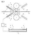
- FIG. 1 shows in a highly simplified representation of a vertical section through a roll stand.
- the rolling stand consists essentially of the two work rolls 2 'and 2'', and the respective support rollers 3' and 3 ''.
- a rolled strip 28 is passed between the two work rolls 2 'and 2''in the direction indicated by the arrow from left to right.
- the device 1 according to the invention is sketched in each case on the upper side and the underside of the rolled strip 28, which sprays an atomised rolling oil in the direction of the roll gap 8.
- the atomization of the rolling oil takes place in each case in a atomizing device 4, which is supplied via lines 6 and 7 rolling oil or air.
- a mixture of air and lubricant particles is formed, which is applied by means of an array of spray nozzles 5 as a spray.
- This spray is deposited on the surface 21 of the work rolls 2 'and 2' 'and / or on the surface 23 of the rolled strip 28, whereby the desired reduction in the friction conditions in the nip 8 is effected.
- rolling oil is collected together with the coolant and recycled by means of a conveying and reprocessing plant.
- FIG. 2 shows an array of spray nozzles 5 on a spray bar 13.
- Each spray nozzle 5 is fed via a first line 6 rolling oil and via a second line 7 air.
- Each spray nozzle 5 generates a spray jet 9, which is formed flat in cross section 15 seen. The juxtaposition of these individual flat spray jets 9 forms a total with respect to the oil concentration total spray 19th
- FIG. 3 shows a cross-sectional view of the atomizing device 4.
- this atomizing device 4 is supplied via a connecting line 6 rolling oil and via another connecting line 7 air.
- the generation of the oil-air mixture takes place in a manner known per se: In a swirling chamber 31, the two media air 27 and oil 26 meet.
- the air 27, which flows at high speed past an orifice of the rolling oil feed 6, entrains oil particles 26, so that a mixture of air and finely divided oil-liquid droplets forms in the swirling chamber 31. Size and design of these liquid droplets can be adjusted in each case by the amount of media supplied and by blending in a wide range.
- These diaphragms in the inlet of air and oil are interchangeable in the atomizer 4.
- This mixture is fed via a short connector of a spray nozzle 5.
- the spray nozzle 5 is spherically curved in the region of an orifice 18.
- two outlet openings 10 are formed in the area of the spherical curvature 12.
- Each of these outlet openings 10 is formed by a slot in the region of the mouth 18. The preparation of this slot in the spherical curvature 10 can be easily done by a cut with a saw blade.
- FIG. 4 shows two views of the mouthpiece 18: in the upper view, the mouthpiece 18 is shown in a sectional view, in the lower view in a three-dimensional view.
- the mouthpiece 18 is convexly curved outwards.
- the curvature 12 is a circular arc.
- a corresponding curvature is also formed on the inner wall of the mouthpiece 18.
- two outlet openings 10 formed by cuts for the mixture are to be seen, which - seen in a direction opposite to the outflow direction - each have the shape of a "C".
- the arrangement of these two C-shaped outlet openings 10 is chosen so that the legs 25 of the two "C" from an axis of symmetry 11 point away.
- the two incisions "C" are back-to-back.
- the production of these outlet openings 10 is effected by cuts.
- the planes of the incisions 10 are at an angle 30 to each other.
- the slot width 14 of these cuts is advantageously between about 0.6 to 0.7 mm.
- FIG. 5 illustrates in a highly simplified representation of the lubrication in the nip
- the upper diagram shows the lubrication with emulsion according to the state of Technique
- the lower illustration represents the inventive application of the rolling oil by means of a spray.
- the lubricant concentration in the nip 8 is lower than in the introduction of the Lubricant in the form of a spray, which is shown in the lower part of the FIG. 5 is illustrated.
- a higher concentration of lubricant forms in the nip 8 compared to emulsion lubrication.
- a comparatively low oil consumption of 50 ml per minute to 200 ml per minute per rolling mill can be achieved.
- Another advantage results from the greatly reduced friction in the nip, whereby the rolling forces and rolling moments for the rolling process can be reduced. Especially during cold rolling, a very good surface quality of the rolled strip can be achieved.
Landscapes
- Engineering & Computer Science (AREA)
- Mechanical Engineering (AREA)
- Metal Rolling (AREA)
- Nozzles (AREA)
Claims (19)
- Procédé pour appliquer un lubrifiant lors du laminage d'un produit laminé métallique, en particulier d'un feuillard laminé (28) passant dans une emprise de laminage (8) entre deux cylindres de travail (2', 2''), comportant les étapes suivantes :- production d'un mélange à partir d'un lubrifiant et d'un gaz porteur dans un dispositif de pulvérisation (4) ;- amenée du mélange à des buses d'aspersion distinctes (5) d'un ensemble de buses d'aspersion (5) pour générer un jet d'aspersion global contigu (19) en direction de la largeur du feuillard laminé, le jet d'aspersion global (19) étant composé de jets d'aspersion (9) qui, en coupe transversale, se présentent sous une forme sensiblement plane ;- application du jet d'aspersion global (19) sur la surface (21) d'au moins l'un des cylindres de travail et/ou sur la surface (23) du feuillard laminé (28),caractérisé en ce que chaque jet d'aspersion (9) est formé au moyen d'une buse d'aspersion (5) qui comporte un nez de buse (18) pourvu d'au moins deux orifices de sortie (10).
- Procédé selon la revendication 1, caractérisé en ce qu'est utilisé un nez de buse (18) présentant une courbure sphérique et au moins deux orifices de sortie (10) agencés symétriquement par rapport à un axe de symétrie (11).
- Procédé selon la revendication 2, caractérisé en ce qu'est utilisé, lors de l'application du jet d'aspersion global (19), un ensemble de buses d'aspersion (5) qui sont agencées en rangée sur une barre d'aspersion (13), et chacune des buses d'aspersion (9) générant un jet d'aspersion (9) qui, vu en coupe transversale, se présente sous une forme sensiblement plane, et chacun des jets d'aspersion (9) étant, vu dans le sens de sa largeur, orienté sensiblement parallèlement à l'axe (24', 24'') d'un cylindre de travail (2', 2'').
- Procédé selon l'une des revendications 1 à 3, caractérisé en ce que de l'air est utilisé comme gaz porteur.
- Procédé selon l'une des revendications 1 à 3, caractérisé en ce qu'une huile de laminage est utilisée comme lubrifiant.
- Procédé selon les revendications 4 et 5, caractérisé en ce que, lors de la production du mélange, de l'huile de laminage et de l'air sont amenés au dispositif de pulvérisation à une température qui correspond à la température ambiante.
- Procédé selon la revendication 6, caractérisé en ce que l'huile de laminage est amenée au dispositif de pulvérisation au moyen d'une pompe de dosage (29).
- Procédé selon la revendication 7, caractérisé en ce que l'huile de laminage est amenée en une quantité inférieure à 200 ml par minute.
- Dispositif pour appliquer un lubrifiant dans l'emprise de laminage d'une cage de laminage, un feuillard laminé métallique (28) passant dans l'emprise de laminage, comprenant :- un dispositif de pulvérisation (4) auquel sont amenés le lubrifiant et un gaz porteur pour produire un mélange à partir du lubrifiant et du gaz porteur ;- un ensemble de buses d'aspersion (5) qui sont reliées au dispositif de pulvérisation (4) et auxquelles le mélange est respectivement amené via des conduites de liaison,caractérisé en ce que chaque buse d'aspersion (5) comporte un nez de buse (18) pourvu d'au moins deux orifices de sortie (10) qui sont aménagés pour générer un jet d'aspersion (9) qui, en coupe transversale, se présente sous une forme sensiblement plane, et qui est dirigé sur la surface (21) d'un cylindre de travail (2', 2'') et/ou sur la surface (23) du feuillard laminé (28).
- Dispositif selon la revendication 9, caractérisé en ce que le nez de buse (18) présente une courbure sphérique dans la zone de la réalisation des au moins deux orifices de sortie (10).
- Dispositif selon la revendication 10, caractérisé en ce que sont ménagés, dans la zone de la courbure sphérique (12) du nez de buse (18), deux orifices de sortie (10) qui sont symétriques par rapport à un axe de symétrie (11) .
- Dispositif selon la revendication 11, caractérisé en ce que les deux orifices de sortie (10) se présentent sous la forme d'un C avec des branches (25) qui vont s'éloignant de l'axe de symétrie (11).
- Dispositif selon l'une des revendications 10 à 11, caractérisé en ce que les orifices de sortie (10) présentent respectivement une largeur (14), cette largeur (14) étant inférieure à un millimètre, et étant de préférence de 0,6 à 0,7 mm.
- Dispositif selon l'une des revendications 9 à 13, caractérisé en ce que l'agencement des jets d'aspersion (5) est choisi de manière telle que les différents jets d'aspersion (9) des buses d'aspersion (5) forment un jet d'aspersion global contigu (19) qui est dirigé sur la surface d'un cylindre de travail (2', 2'') et qui présente un côté large qui est orienté sensiblement parallèlement à l'axe (24', 24'') du cylindre de travail (2', 2'').
- Dispositif selon l'une des revendications 9 à 13, caractérisé en ce que le lubrifiant est une huile de laminage et le gaz porteur, de l'air.
- Dispositif selon la revendication 15, caractérisé en ce que l'huile de laminage est amenée au dispositif de pulvérisation (4) au moyen d'une pompe de dosage (29).
- Dispositif selon la revendication 16, caractérisé en ce que la pompe de dosage (29) amène l'huile de laminage au dispositif de pulvérisation (4) avec un débit volumétrique inférieur à 200 ml par minute.
- Dispositif selon la revendication 16, caractérisé en ce que l'huile de laminage présente une température qui correspond approximativement à la température ambiante de la cage de laminage.
- Dispositif selon la revendication 11, caractérisé en ce que les deux orifices de sortie (10) sont formés par des entailles dans le nez de buse (18) situées respectivement dans un plan, les plans formant entre eux un angle (30).
Priority Applications (1)
| Application Number | Priority Date | Filing Date | Title |
|---|---|---|---|
| EP11749856.8A EP2651577B1 (fr) | 2010-12-16 | 2011-09-02 | Procédé et dispositif pour répandre un lubrifiant lors du laminage d'un produit laminé métallique |
Applications Claiming Priority (3)
| Application Number | Priority Date | Filing Date | Title |
|---|---|---|---|
| EP10195330A EP2465619A1 (fr) | 2010-12-16 | 2010-12-16 | Procédé et dispositif d'application d'un lubrifiant lors du laminage d'un produit de laminage métallique |
| PCT/EP2011/065165 WO2012079785A1 (fr) | 2010-12-16 | 2011-09-02 | Procédé et dispositif pour répandre un lubrifiant lors du laminage d'un produit laminé métallique |
| EP11749856.8A EP2651577B1 (fr) | 2010-12-16 | 2011-09-02 | Procédé et dispositif pour répandre un lubrifiant lors du laminage d'un produit laminé métallique |
Publications (2)
| Publication Number | Publication Date |
|---|---|
| EP2651577A1 EP2651577A1 (fr) | 2013-10-23 |
| EP2651577B1 true EP2651577B1 (fr) | 2015-01-28 |
Family
ID=44025288
Family Applications (2)
| Application Number | Title | Priority Date | Filing Date |
|---|---|---|---|
| EP10195330A Withdrawn EP2465619A1 (fr) | 2010-12-16 | 2010-12-16 | Procédé et dispositif d'application d'un lubrifiant lors du laminage d'un produit de laminage métallique |
| EP11749856.8A Active EP2651577B1 (fr) | 2010-12-16 | 2011-09-02 | Procédé et dispositif pour répandre un lubrifiant lors du laminage d'un produit laminé métallique |
Family Applications Before (1)
| Application Number | Title | Priority Date | Filing Date |
|---|---|---|---|
| EP10195330A Withdrawn EP2465619A1 (fr) | 2010-12-16 | 2010-12-16 | Procédé et dispositif d'application d'un lubrifiant lors du laminage d'un produit de laminage métallique |
Country Status (6)
| Country | Link |
|---|---|
| US (1) | US9314827B2 (fr) |
| EP (2) | EP2465619A1 (fr) |
| KR (1) | KR101807527B1 (fr) |
| CN (1) | CN103249504B (fr) |
| RU (1) | RU2570257C2 (fr) |
| WO (1) | WO2012079785A1 (fr) |
Cited By (5)
| Publication number | Priority date | Publication date | Assignee | Title |
|---|---|---|---|---|
| EP3238843A1 (fr) | 2016-04-29 | 2017-11-01 | Primetals Technologies Austria GmbH | Procede de laminage d'un produit de laminage |
| EP3517228A1 (fr) | 2018-01-29 | 2019-07-31 | Primetals Technologies Austria GmbH | Règles d'un processus de laminage |
| WO2020221654A1 (fr) | 2019-04-30 | 2020-11-05 | Primetals Technologies Austria GmbH | Laminage d'un produit laminé |
| WO2021048038A1 (fr) | 2019-09-10 | 2021-03-18 | Primetals Technologies Austria GmbH | Laminage à froid de produit laminé dans un train de laminoirs à multiples cages de laminoir |
| EP4501480A1 (fr) | 2023-08-03 | 2025-02-05 | Primetals Technologies Austria GmbH | Procédé et système pour l'application d'un lubrifiant lors du laminage à froid d'un produit à laminer dans une cage de laminoir |
Families Citing this family (17)
| Publication number | Priority date | Publication date | Assignee | Title |
|---|---|---|---|---|
| DE102008050392A1 (de) * | 2008-06-18 | 2009-12-24 | Sms Siemag Aktiengesellschaft | Verfahren und Vorrichtung zum Schmieren von Walzen und eines Walzbandes eines Walzgerüsts |
| CN102430596A (zh) * | 2010-09-29 | 2012-05-02 | 山东莱芜金石集团有限公司 | 表面清刷机 |
| EP2465619A1 (fr) | 2010-12-16 | 2012-06-20 | Siemens VAI Metals Technologies GmbH | Procédé et dispositif d'application d'un lubrifiant lors du laminage d'un produit de laminage métallique |
| GB2511512B (en) * | 2013-03-05 | 2015-06-10 | Siemens Plc | Cooling device & method |
| EP2893986A1 (fr) | 2014-01-08 | 2015-07-15 | Siemens VAI Metals Technologies GmbH | Lubrification à l'aide de buses d'injection dotées de plusieurs orifices d'entrée d'huile |
| CN104942031B (zh) * | 2014-03-26 | 2017-05-31 | 宝山钢铁股份有限公司 | 一种冷轧轧制润滑剂供给方法 |
| JP6350274B2 (ja) * | 2014-12-26 | 2018-07-04 | 新日鐵住金株式会社 | 冷間圧延機の潤滑油供給設備 |
| CN104985009B (zh) * | 2015-07-31 | 2017-08-01 | 张正秀 | 一种金属板带冷轧用润滑设备、润滑方法及轧制油 |
| CN105665177B (zh) * | 2016-03-22 | 2018-12-14 | 苏州吉岛电极科技有限公司 | 自动喷涂机 |
| EP3251762B1 (fr) | 2016-06-02 | 2019-08-07 | Primetals Technologies Austria GmbH | Dispositif de lubrification pour l'application d'un lubrifiant lors du laminage d'un produit de laminage |
| KR102357445B1 (ko) * | 2016-09-23 | 2022-01-28 | 타타 스틸 네덜란드 테크날러지 베.뷔. | 이동하는 강 스트립의 액체-보조 레이저 텍스쳐링을 위한 방법 및 장치 |
| EP3308868B1 (fr) * | 2016-10-17 | 2022-12-07 | Primetals Technologies Austria GmbH | Refroidissement d'un rouleau d'une cage de laminoir |
| EP3461566A1 (fr) | 2017-10-02 | 2019-04-03 | Primetals Technologies Austria GmbH | Laminage d'un laminé |
| EP3808466A1 (fr) * | 2019-10-16 | 2021-04-21 | Primetals Technologies Germany GmbH | Dispositif de refroidissement à rayonnement de refroidissement pourvu de section transversale creuse |
| CN111604378A (zh) * | 2020-06-24 | 2020-09-01 | 瓯锟科技温州有限公司 | 一种立式金属板带摩擦复合装置 |
| CN112692073B (zh) * | 2020-12-27 | 2023-03-24 | 浙江传播者金属装饰材料有限公司 | 一种防轧机打滑装置及其使用方法 |
| CN112453062B (zh) * | 2020-12-29 | 2021-07-06 | 浙江传播者金属装饰材料有限公司 | 一种轧机打滑补油装置及其使用方法 |
Family Cites Families (11)
| Publication number | Priority date | Publication date | Assignee | Title |
|---|---|---|---|---|
| DE1184287B (de) * | 1957-04-18 | 1964-12-23 | Davy & United Eng Co Ltd | Duese zum Erzeugen eines flachen Schmieroelstrahls, insbesondere fuer die Bearbeitung von Blechbahnen |
| SU1227275A1 (ru) | 1984-07-04 | 1986-04-30 | Всесоюзный Научно-Исследовательский И Проектный Институт По Очистке Технологических Газов,Сточных Вод И Использованию Вторичных Энергоресурсов Предприятий Черной Металлургии | Способ охлаждени прокатных валков в процессе прокатки |
| SU1311798A1 (ru) | 1984-10-15 | 1987-05-23 | Институт черной металлургии | Валковый узел прокатной клети |
| IL110797A (en) * | 1993-09-15 | 1997-09-30 | Electric Power Res Inst | Fluid atomizer |
| DE10131369A1 (de) | 2001-06-28 | 2003-01-09 | Sms Demag Ag | Verfahren und Vorrichtung zum Kühlen und Schmieren von Walzen eines Walzgerüstes |
| ITTV20050015A1 (it) * | 2005-01-31 | 2006-08-01 | Riversdale Invest Ltd | Struttura di ugello particolarmente per la atomizzazione di un liquido |
| CA2697889C (fr) | 2007-08-28 | 2012-10-02 | Air Products And Chemicals, Inc. | Procede et appareil de decharge d'un spray cryogenique non lineaire sur la largeur d'une cage de laminoir |
| BE1017806A3 (fr) | 2007-10-08 | 2009-07-07 | Ct Rech Metallurgiques Asbl | Installation et procede de lubrification par atomisation pour cylindres de laminage. |
| DE102008050392A1 (de) * | 2008-06-18 | 2009-12-24 | Sms Siemag Aktiengesellschaft | Verfahren und Vorrichtung zum Schmieren von Walzen und eines Walzbandes eines Walzgerüsts |
| RU81911U1 (ru) | 2008-09-01 | 2009-04-10 | Открытое акционерное общество "Западно-Сибирский металлургический комбинат" | Устройство для ускоренного охлаждения и гидротранспортирования шахтной стойки |
| EP2465619A1 (fr) | 2010-12-16 | 2012-06-20 | Siemens VAI Metals Technologies GmbH | Procédé et dispositif d'application d'un lubrifiant lors du laminage d'un produit de laminage métallique |
-
2010
- 2010-12-16 EP EP10195330A patent/EP2465619A1/fr not_active Withdrawn
-
2011
- 2011-09-02 WO PCT/EP2011/065165 patent/WO2012079785A1/fr not_active Ceased
- 2011-09-02 US US13/995,028 patent/US9314827B2/en active Active
- 2011-09-02 EP EP11749856.8A patent/EP2651577B1/fr active Active
- 2011-09-02 KR KR1020137018514A patent/KR101807527B1/ko active Active
- 2011-09-02 RU RU2013132745/02A patent/RU2570257C2/ru active
- 2011-09-02 CN CN201180060262.1A patent/CN103249504B/zh active Active
Cited By (11)
| Publication number | Priority date | Publication date | Assignee | Title |
|---|---|---|---|---|
| EP3238843A1 (fr) | 2016-04-29 | 2017-11-01 | Primetals Technologies Austria GmbH | Procede de laminage d'un produit de laminage |
| WO2017186910A1 (fr) | 2016-04-29 | 2017-11-02 | Primetals Technologies Austria GmbH | Procédé pour laminer une matière à laminer |
| US11161161B2 (en) | 2016-04-29 | 2021-11-02 | Primetals Technologies Austria GmbH | Method for rolling a product to be rolled |
| EP3517228A1 (fr) | 2018-01-29 | 2019-07-31 | Primetals Technologies Austria GmbH | Règles d'un processus de laminage |
| WO2019145079A1 (fr) | 2018-01-29 | 2019-08-01 | Primetals Technologies Austria GmbH | Réglage d'un processus de laminage |
| WO2020221654A1 (fr) | 2019-04-30 | 2020-11-05 | Primetals Technologies Austria GmbH | Laminage d'un produit laminé |
| US11529660B2 (en) | 2019-04-30 | 2022-12-20 | Primetals Technologies Austria GmbH | Rolling of a rolled material |
| WO2021048038A1 (fr) | 2019-09-10 | 2021-03-18 | Primetals Technologies Austria GmbH | Laminage à froid de produit laminé dans un train de laminoirs à multiples cages de laminoir |
| US12103061B2 (en) | 2019-09-10 | 2024-10-01 | Primetals Technologies Austria GmbH | Cold rolling rolled stock in a mill train with multiple roll stands |
| EP4501480A1 (fr) | 2023-08-03 | 2025-02-05 | Primetals Technologies Austria GmbH | Procédé et système pour l'application d'un lubrifiant lors du laminage à froid d'un produit à laminer dans une cage de laminoir |
| WO2025026608A1 (fr) | 2023-08-03 | 2025-02-06 | Primetals Technologies Austria GmbH | Procédé et système d'application d'un lubrifiant pendant le laminage à froid d'un produit de laminage sur un support de laminage |
Also Published As
| Publication number | Publication date |
|---|---|
| RU2570257C2 (ru) | 2015-12-10 |
| US20130298627A1 (en) | 2013-11-14 |
| KR20130124354A (ko) | 2013-11-13 |
| KR101807527B1 (ko) | 2017-12-11 |
| US9314827B2 (en) | 2016-04-19 |
| EP2651577A1 (fr) | 2013-10-23 |
| CN103249504A (zh) | 2013-08-14 |
| CN103249504B (zh) | 2015-05-06 |
| RU2013132745A (ru) | 2015-01-27 |
| WO2012079785A1 (fr) | 2012-06-21 |
| EP2465619A1 (fr) | 2012-06-20 |
Similar Documents
| Publication | Publication Date | Title |
|---|---|---|
| EP2651577B1 (fr) | Procédé et dispositif pour répandre un lubrifiant lors du laminage d'un produit laminé métallique | |
| EP2303480B1 (fr) | Procédé et dispositif de lubrification de cylindres et d'un feuillard d'une cage de laminoir | |
| DE60213347T3 (de) | Düse zur luftunterstützten Zerstäubung von Flüssigkeiten | |
| DE2939951C2 (fr) | ||
| EP1399276B1 (fr) | Procede et dispositif de tuyeres destines a la lubrification variable en largeur de l'emprise d'une structure de laminage | |
| DE2401649B2 (de) | Verfahren zum kuehlen eines stranges und spruehduese | |
| EP2866957B1 (fr) | Procédé et dispositif de refroidissement de surfaces dans des installations de coulée, de laminage, ou autres installations de traitement de bandes | |
| EP2750813B1 (fr) | Laminoir réversible et procédé de fonctionnement pour un laminoir réversible | |
| EP2590783A1 (fr) | Ajutage pour lubrifiant réfrigérant | |
| WO2014026992A2 (fr) | Dispositif à buse de pulvérisation, destiné en particulier à asperger une barre de coulée | |
| DE69622733T2 (de) | Landwirtschaftliche und andere sprühsysteme | |
| DE4337438C2 (de) | Verfahren zum Durchlauf-Vakuum-Rundumbeschichten und Vakuum-Durchlauf-Rundum-Beschichtungskammer zur Durchführung des Verfahrens | |
| DE202010015304U1 (de) | Düse | |
| DE102011106494A1 (de) | Düsenvorrichtung und Strangführungsvorrichtung mit der Düsenvorrichtung | |
| AT413082B (de) | Verfahren und vorrichtung zum zerstäuben von flüssigkeitsfilmen | |
| DE602004012810T2 (de) | Verfahren und Vorrichtung zur Schmierung von Walzwerkswalzen | |
| DE2341988B2 (de) | Vorrichtung zur Erzeugung eines dichten Sprühnebels (Aerosols) | |
| EP4501480A1 (fr) | Procédé et système pour l'application d'un lubrifiant lors du laminage à froid d'un produit à laminer dans une cage de laminoir | |
| DE69504290T2 (de) | Vorrichtung zum Versprühen von einem Flüssigkeit-Luft-Gemisch | |
| DE3207197A1 (de) | Vorrichtung zur erzeugung eines spruehstrahls | |
| DE102021211661A1 (de) | Fluidbehandlung eines bandförmigen Walzprodukts | |
| DE102008048048A1 (de) | Fluidausstoß-Vorrichtung | |
| DE1557044C (de) | Vorrichtung zum Dispergieren einer Flüssigkeit in ein gasförmiges Medium | |
| DE102005002392A1 (de) | Verfahren zur schnellen Erzeugung eines beständigen Aerosols und dazugehörige Düsen zur Durchführung des Verfahrens | |
| AT7094U2 (de) | Verfahren und vorrichtung zum zerstäuben von flüssigkeitsfilmen |
Legal Events
| Date | Code | Title | Description |
|---|---|---|---|
| PUAI | Public reference made under article 153(3) epc to a published international application that has entered the european phase |
Free format text: ORIGINAL CODE: 0009012 |
|
| 17P | Request for examination filed |
Effective date: 20130503 |
|
| AK | Designated contracting states |
Kind code of ref document: A1 Designated state(s): AL AT BE BG CH CY CZ DE DK EE ES FI FR GB GR HR HU IE IS IT LI LT LU LV MC MK MT NL NO PL PT RO RS SE SI SK SM TR |
|
| DAX | Request for extension of the european patent (deleted) | ||
| GRAP | Despatch of communication of intention to grant a patent |
Free format text: ORIGINAL CODE: EPIDOSNIGR1 |
|
| INTG | Intention to grant announced |
Effective date: 20140821 |
|
| GRAS | Grant fee paid |
Free format text: ORIGINAL CODE: EPIDOSNIGR3 |
|
| GRAA | (expected) grant |
Free format text: ORIGINAL CODE: 0009210 |
|
| AK | Designated contracting states |
Kind code of ref document: B1 Designated state(s): AL AT BE BG CH CY CZ DE DK EE ES FI FR GB GR HR HU IE IS IT LI LT LU LV MC MK MT NL NO PL PT RO RS SE SI SK SM TR |
|
| REG | Reference to a national code |
Ref country code: GB Ref legal event code: FG4D Free format text: NOT ENGLISH |
|
| REG | Reference to a national code |
Ref country code: CH Ref legal event code: EP |
|
| REG | Reference to a national code |
Ref country code: IE Ref legal event code: FG4D Free format text: LANGUAGE OF EP DOCUMENT: GERMAN |
|
| REG | Reference to a national code |
Ref country code: AT Ref legal event code: REF Ref document number: 708007 Country of ref document: AT Kind code of ref document: T Effective date: 20150315 |
|
| REG | Reference to a national code |
Ref country code: DE Ref legal event code: R096 Ref document number: 502011005806 Country of ref document: DE Effective date: 20150319 |
|
| REG | Reference to a national code |
Ref country code: SE Ref legal event code: TRGR |
|
| REG | Reference to a national code |
Ref country code: NL Ref legal event code: VDEP Effective date: 20150128 |
|
| RAP2 | Party data changed (patent owner data changed or rights of a patent transferred) |
Owner name: PRIMETALS TECHNOLOGIES AUSTRIA GMBH |
|
| REG | Reference to a national code |
Ref country code: LT Ref legal event code: MG4D |
|
| PG25 | Lapsed in a contracting state [announced via postgrant information from national office to epo] |
Ref country code: FI Free format text: LAPSE BECAUSE OF FAILURE TO SUBMIT A TRANSLATION OF THE DESCRIPTION OR TO PAY THE FEE WITHIN THE PRESCRIBED TIME-LIMIT Effective date: 20150128 Ref country code: HR Free format text: LAPSE BECAUSE OF FAILURE TO SUBMIT A TRANSLATION OF THE DESCRIPTION OR TO PAY THE FEE WITHIN THE PRESCRIBED TIME-LIMIT Effective date: 20150128 Ref country code: LT Free format text: LAPSE BECAUSE OF FAILURE TO SUBMIT A TRANSLATION OF THE DESCRIPTION OR TO PAY THE FEE WITHIN THE PRESCRIBED TIME-LIMIT Effective date: 20150128 Ref country code: NO Free format text: LAPSE BECAUSE OF FAILURE TO SUBMIT A TRANSLATION OF THE DESCRIPTION OR TO PAY THE FEE WITHIN THE PRESCRIBED TIME-LIMIT Effective date: 20150428 Ref country code: BG Free format text: LAPSE BECAUSE OF FAILURE TO SUBMIT A TRANSLATION OF THE DESCRIPTION OR TO PAY THE FEE WITHIN THE PRESCRIBED TIME-LIMIT Effective date: 20150428 Ref country code: ES Free format text: LAPSE BECAUSE OF FAILURE TO SUBMIT A TRANSLATION OF THE DESCRIPTION OR TO PAY THE FEE WITHIN THE PRESCRIBED TIME-LIMIT Effective date: 20150128 |
|
| PG25 | Lapsed in a contracting state [announced via postgrant information from national office to epo] |
Ref country code: IS Free format text: LAPSE BECAUSE OF FAILURE TO SUBMIT A TRANSLATION OF THE DESCRIPTION OR TO PAY THE FEE WITHIN THE PRESCRIBED TIME-LIMIT Effective date: 20150528 Ref country code: LV Free format text: LAPSE BECAUSE OF FAILURE TO SUBMIT A TRANSLATION OF THE DESCRIPTION OR TO PAY THE FEE WITHIN THE PRESCRIBED TIME-LIMIT Effective date: 20150128 Ref country code: GR Free format text: LAPSE BECAUSE OF FAILURE TO SUBMIT A TRANSLATION OF THE DESCRIPTION OR TO PAY THE FEE WITHIN THE PRESCRIBED TIME-LIMIT Effective date: 20150429 Ref country code: RS Free format text: LAPSE BECAUSE OF FAILURE TO SUBMIT A TRANSLATION OF THE DESCRIPTION OR TO PAY THE FEE WITHIN THE PRESCRIBED TIME-LIMIT Effective date: 20150128 Ref country code: PL Free format text: LAPSE BECAUSE OF FAILURE TO SUBMIT A TRANSLATION OF THE DESCRIPTION OR TO PAY THE FEE WITHIN THE PRESCRIBED TIME-LIMIT Effective date: 20150128 Ref country code: NL Free format text: LAPSE BECAUSE OF FAILURE TO SUBMIT A TRANSLATION OF THE DESCRIPTION OR TO PAY THE FEE WITHIN THE PRESCRIBED TIME-LIMIT Effective date: 20150128 |
|
| REG | Reference to a national code |
Ref country code: DE Ref legal event code: R097 Ref document number: 502011005806 Country of ref document: DE |
|
| PG25 | Lapsed in a contracting state [announced via postgrant information from national office to epo] |
Ref country code: EE Free format text: LAPSE BECAUSE OF FAILURE TO SUBMIT A TRANSLATION OF THE DESCRIPTION OR TO PAY THE FEE WITHIN THE PRESCRIBED TIME-LIMIT Effective date: 20150128 Ref country code: CZ Free format text: LAPSE BECAUSE OF FAILURE TO SUBMIT A TRANSLATION OF THE DESCRIPTION OR TO PAY THE FEE WITHIN THE PRESCRIBED TIME-LIMIT Effective date: 20150128 Ref country code: RO Free format text: LAPSE BECAUSE OF FAILURE TO SUBMIT A TRANSLATION OF THE DESCRIPTION OR TO PAY THE FEE WITHIN THE PRESCRIBED TIME-LIMIT Effective date: 20150128 Ref country code: SK Free format text: LAPSE BECAUSE OF FAILURE TO SUBMIT A TRANSLATION OF THE DESCRIPTION OR TO PAY THE FEE WITHIN THE PRESCRIBED TIME-LIMIT Effective date: 20150128 Ref country code: DK Free format text: LAPSE BECAUSE OF FAILURE TO SUBMIT A TRANSLATION OF THE DESCRIPTION OR TO PAY THE FEE WITHIN THE PRESCRIBED TIME-LIMIT Effective date: 20150128 |
|
| PGFP | Annual fee paid to national office [announced via postgrant information from national office to epo] |
Ref country code: SE Payment date: 20150907 Year of fee payment: 5 |
|
| PLBE | No opposition filed within time limit |
Free format text: ORIGINAL CODE: 0009261 |
|
| STAA | Information on the status of an ep patent application or granted ep patent |
Free format text: STATUS: NO OPPOSITION FILED WITHIN TIME LIMIT |
|
| 26N | No opposition filed |
Effective date: 20151029 |
|
| PG25 | Lapsed in a contracting state [announced via postgrant information from national office to epo] |
Ref country code: SI Free format text: LAPSE BECAUSE OF FAILURE TO SUBMIT A TRANSLATION OF THE DESCRIPTION OR TO PAY THE FEE WITHIN THE PRESCRIBED TIME-LIMIT Effective date: 20150128 |
|
| PG25 | Lapsed in a contracting state [announced via postgrant information from national office to epo] |
Ref country code: LU Free format text: LAPSE BECAUSE OF FAILURE TO SUBMIT A TRANSLATION OF THE DESCRIPTION OR TO PAY THE FEE WITHIN THE PRESCRIBED TIME-LIMIT Effective date: 20150902 Ref country code: MC Free format text: LAPSE BECAUSE OF FAILURE TO SUBMIT A TRANSLATION OF THE DESCRIPTION OR TO PAY THE FEE WITHIN THE PRESCRIBED TIME-LIMIT Effective date: 20150128 |
|
| REG | Reference to a national code |
Ref country code: CH Ref legal event code: PL |
|
| GBPC | Gb: european patent ceased through non-payment of renewal fee |
Effective date: 20150902 |
|
| REG | Reference to a national code |
Ref country code: IE Ref legal event code: MM4A |
|
| PG25 | Lapsed in a contracting state [announced via postgrant information from national office to epo] |
Ref country code: CH Free format text: LAPSE BECAUSE OF NON-PAYMENT OF DUE FEES Effective date: 20150930 Ref country code: LI Free format text: LAPSE BECAUSE OF NON-PAYMENT OF DUE FEES Effective date: 20150930 Ref country code: IE Free format text: LAPSE BECAUSE OF NON-PAYMENT OF DUE FEES Effective date: 20150902 Ref country code: GB Free format text: LAPSE BECAUSE OF NON-PAYMENT OF DUE FEES Effective date: 20150902 |
|
| REG | Reference to a national code |
Ref country code: DE Ref legal event code: R082 Ref document number: 502011005806 Country of ref document: DE Representative=s name: KINNSTAETTER, KLAUS, DIPL.-PHYS.UNIV., DE |
|
| REG | Reference to a national code |
Ref country code: DE Ref legal event code: R082 Ref document number: 502011005806 Country of ref document: DE Representative=s name: KINNSTAETTER, KLAUS, DIPL.-PHYS.UNIV., DE Ref country code: DE Ref legal event code: R081 Ref document number: 502011005806 Country of ref document: DE Owner name: PRIMETALS TECHNOLOGIES AUSTRIA GMBH, AT Free format text: FORMER OWNER: SIEMENS VAI METALS TECHNOLOGIES GMBH, LINZ, AT |
|
| REG | Reference to a national code |
Ref country code: FR Ref legal event code: PLFP Year of fee payment: 6 |
|
| PG25 | Lapsed in a contracting state [announced via postgrant information from national office to epo] |
Ref country code: MT Free format text: LAPSE BECAUSE OF FAILURE TO SUBMIT A TRANSLATION OF THE DESCRIPTION OR TO PAY THE FEE WITHIN THE PRESCRIBED TIME-LIMIT Effective date: 20150128 |
|
| REG | Reference to a national code |
Ref country code: AT Ref legal event code: PC Ref document number: 708007 Country of ref document: AT Kind code of ref document: T Owner name: PRIMETALS TECHNOLOGIES AUSTRIA GMBH, AT Effective date: 20170314 |
|
| PG25 | Lapsed in a contracting state [announced via postgrant information from national office to epo] |
Ref country code: SE Free format text: LAPSE BECAUSE OF NON-PAYMENT OF DUE FEES Effective date: 20160903 |
|
| REG | Reference to a national code |
Ref country code: SE Ref legal event code: EUG |
|
| PG25 | Lapsed in a contracting state [announced via postgrant information from national office to epo] |
Ref country code: HU Free format text: LAPSE BECAUSE OF FAILURE TO SUBMIT A TRANSLATION OF THE DESCRIPTION OR TO PAY THE FEE WITHIN THE PRESCRIBED TIME-LIMIT; INVALID AB INITIO Effective date: 20110902 Ref country code: SM Free format text: LAPSE BECAUSE OF FAILURE TO SUBMIT A TRANSLATION OF THE DESCRIPTION OR TO PAY THE FEE WITHIN THE PRESCRIBED TIME-LIMIT Effective date: 20150128 |
|
| PG25 | Lapsed in a contracting state [announced via postgrant information from national office to epo] |
Ref country code: CY Free format text: LAPSE BECAUSE OF FAILURE TO SUBMIT A TRANSLATION OF THE DESCRIPTION OR TO PAY THE FEE WITHIN THE PRESCRIBED TIME-LIMIT Effective date: 20150128 |
|
| PG25 | Lapsed in a contracting state [announced via postgrant information from national office to epo] |
Ref country code: BE Free format text: LAPSE BECAUSE OF NON-PAYMENT OF DUE FEES Effective date: 20150930 |
|
| REG | Reference to a national code |
Ref country code: FR Ref legal event code: PLFP Year of fee payment: 7 |
|
| PG25 | Lapsed in a contracting state [announced via postgrant information from national office to epo] |
Ref country code: PT Free format text: LAPSE BECAUSE OF FAILURE TO SUBMIT A TRANSLATION OF THE DESCRIPTION OR TO PAY THE FEE WITHIN THE PRESCRIBED TIME-LIMIT Effective date: 20150128 Ref country code: MK Free format text: LAPSE BECAUSE OF FAILURE TO SUBMIT A TRANSLATION OF THE DESCRIPTION OR TO PAY THE FEE WITHIN THE PRESCRIBED TIME-LIMIT Effective date: 20150128 |
|
| REG | Reference to a national code |
Ref country code: FR Ref legal event code: PLFP Year of fee payment: 8 |
|
| PG25 | Lapsed in a contracting state [announced via postgrant information from national office to epo] |
Ref country code: AL Free format text: LAPSE BECAUSE OF FAILURE TO SUBMIT A TRANSLATION OF THE DESCRIPTION OR TO PAY THE FEE WITHIN THE PRESCRIBED TIME-LIMIT Effective date: 20150128 |
|
| REG | Reference to a national code |
Ref country code: DE Ref legal event code: R082 Ref document number: 502011005806 Country of ref document: DE Representative=s name: LINDNER BLAUMEIER, PATENT- UND RECHTSANWAELTE,, DE |
|
| PGFP | Annual fee paid to national office [announced via postgrant information from national office to epo] |
Ref country code: DE Payment date: 20250919 Year of fee payment: 15 |
|
| PGFP | Annual fee paid to national office [announced via postgrant information from national office to epo] |
Ref country code: IT Payment date: 20250923 Year of fee payment: 15 Ref country code: TR Payment date: 20250826 Year of fee payment: 15 |
|
| PGFP | Annual fee paid to national office [announced via postgrant information from national office to epo] |
Ref country code: AT Payment date: 20250919 Year of fee payment: 15 Ref country code: FR Payment date: 20250922 Year of fee payment: 15 |