EP2651605B1 - Eintreibvorrichtung zum eintreiben von befestigungselementen auf einem patronengurt - Google Patents
Eintreibvorrichtung zum eintreiben von befestigungselementen auf einem patronengurt Download PDFInfo
- Publication number
- EP2651605B1 EP2651605B1 EP11808443.3A EP11808443A EP2651605B1 EP 2651605 B1 EP2651605 B1 EP 2651605B1 EP 11808443 A EP11808443 A EP 11808443A EP 2651605 B1 EP2651605 B1 EP 2651605B1
- Authority
- EP
- European Patent Office
- Prior art keywords
- driving
- cartridge belt
- conveying
- cycle
- driving tool
- Prior art date
- Legal status (The legal status is an assumption and is not a legal conclusion. Google has not performed a legal analysis and makes no representation as to the accuracy of the status listed.)
- Active
Links
Images


Classifications
-
- B—PERFORMING OPERATIONS; TRANSPORTING
- B25—HAND TOOLS; PORTABLE POWER-DRIVEN TOOLS; MANIPULATORS
- B25C—HAND-HELD NAILING OR STAPLING TOOLS; MANUALLY OPERATED PORTABLE STAPLING TOOLS
- B25C1/00—Hand-held nailing tools; Nail feeding devices
- B25C1/001—Nail feeding devices
- B25C1/003—Nail feeding devices for belts of nails
-
- B—PERFORMING OPERATIONS; TRANSPORTING
- B25—HAND TOOLS; PORTABLE POWER-DRIVEN TOOLS; MANIPULATORS
- B25C—HAND-HELD NAILING OR STAPLING TOOLS; MANUALLY OPERATED PORTABLE STAPLING TOOLS
- B25C1/00—Hand-held nailing tools; Nail feeding devices
- B25C1/008—Safety devices
-
- B—PERFORMING OPERATIONS; TRANSPORTING
- B25—HAND TOOLS; PORTABLE POWER-DRIVEN TOOLS; MANIPULATORS
- B25C—HAND-HELD NAILING OR STAPLING TOOLS; MANUALLY OPERATED PORTABLE STAPLING TOOLS
- B25C1/00—Hand-held nailing tools; Nail feeding devices
- B25C1/04—Hand-held nailing tools; Nail feeding devices operated by fluid pressure, e.g. by air pressure
Definitions
- the present invention relates to a driving tool for driving fasteners on a cartridge belt into workpieces as claimed in the pre-characterizing clause of claim 1, and to a method for driving in fasteners on a cartridge belt as claimed in the pre-characterizing clause of claim 13.
- the driving tool in question is used especially as a hand tool in the construction industry, for example for fastening particle boards to support structures.
- the driving device in question can also be associated with an automatic positioning unit such as a robot, as part of an automated manufacturing process.
- the driving tool can here be a "pushing” driving tool or a “shooting” driving tool.
- the present invention can be applied to both types of driving tool.
- fastener should be understood in the broadest sense and includes screws, pins or the like in addition to nails and staples. The focus here is on the driving in of nails but this should not be understood as implying any limitation.
- the fasteners are here provided grouped together as a cartridge belt.
- the cartridge belt can have a plastic or metal support belt that carries the individual fasteners.
- Another alternative embodiment consists in providing a row of parallel fastening wires that are attached to the individual fasteners. The important thing here is that in the present case the cartridge belt comprises both the fasteners and the respective support medium.
- the cartridge belt can be a cartridge strip or a wound-up cartridge coil.
- the tool is then accordingly either a so-called strip nailer or a so-called coil nailer.
- a driving cycle is generally combined with a conveying cycle for the cartridge belt along a conveying path so that manual "loading" is not necessary before or after a driving cycle.
- a known coil nailer ( EP 1 648 662 B1 ), on which the present invention is based, is equipped with a mechanical cartridge belt limit switch that senses in the driving channel whether there is a nail in the driving channel.
- the driving channel is the channel out of which the respective fastener, the nail in this case, is driven into the workpiece.
- the cartridge belt limit switch initiates the deactivation of the driving tool.
- the deactivation here means that a workpiece contact, which is depressed in normal operation when the driving tool is placed against the workpiece, is blocked, preventing a further driving cycle from being carried out.
- a disadvantage of the known driving tool is that the sensing of the fastener in the driving channel is only possible with very specific fasteners. There is also a risk that the fastener could get caught in the driving channel so there is a likelihood of limited operational safety in certain applications.
- WO 2008/032861 A1 shows a driving tool with a magazine including a feeder. When only few fasteners remain in the magazine, a feeder engagement portion pushes a lock arm into a position locking the next nail striking operation.
- US 2010/127035 A1 discloses a further driving tool with a lock mechanism. When the last nail has been shot out, a sliding member enters the drive channel deactivating the tool. With the driving tool of US 2009/127310A1 , a position of the nail pusher in which no fasteners remain in the magazine, leads to deactivation of the driving tool.
- the object of the invention is to design and develop the known driving tool in such a way that there is greater flexibility in its application at the same time as increased operational safety.
- the cartridge belt limit switch sensing cannot be carried out in the driving channel but instead upstream of the driving channel with respect to the conveying direction, as long as, after a cartridge belt is no longer present at the sensing point, the cartridge belt limit switch still allows a last driving cycle or a last group of driving cycles to be carried out. Only after the last driving cycle or the last group of driving cycles has been completed does the cartridge belt limit switch then initiate the deactivation of the driving tool.
- the inventive step of the invention therefore consists in providing the sensing point of the cartridge belt limit switch at a point in the conveying path that is remote from the driving channel, wherein it must be ensured that the last fastener remaining in the cartridge belt or the last conveying means remaining in the cartridge belt can be driven in, and in that the conveying drive means for the cartridge belt can be used in a simple fashion to implement the above-proposed "delayed" deactivation of the driving tool after a cartridge belt is no longer present at the sensing point.
- the sensing can to a large extent be carried out universally on a wide variety of fasteners without affecting the resulting operational safety.
- the dual purpose of the conveying drive means results in a particularly compact structure. It should be pointed out that the sensing whether a sensing point is occupied by the cartridge belt means that it is determined whether the cartridge belt is or is not present. Sensing of the fasteners on the cartridge belt itself or sensing of the conveying belt can be provided here. The focus is here preferably on the sensing of the conveying belt, it being assumed that the cartridge belt is fully loaded with fasteners, i.e. as far as the last occupied position.
- the driving tool is deactivated by blocking the depression of the workpiece contact, wherein in one alternative embodiment the blocking is effected by a toothed rack between the workpiece contact and a blocking lever.
- a toothed rack makes it possible to block in a simple fashion the depressed workpiece contact at different depths.
- the basic idea of equipping the driving tool with an abovementioned blocking toothed rack is also claimable, as will be explained.
- the particularly preferred embodiments in claims 9 to 11 concern the concept of designing the cartridge belt limit switch in the manner of a mechanical memory that can be placed in a reset mode, a preset mode and a set mode. Normally, i.e. when there is a cartridge belt at the sensing point, the cartridge belt limit switch always remains in the reset mode so that driving cycles and conveying cycles can take place unaffected. When a cartridge belt is no longer present at the sensing point, this causes the cartridge belt limit switch to be transferred into the preset mode, following which a subsequent conveying cycle causes the transition of the cartridge belt limit switch into the set mode, which in turn is combined with the deactivation of the driving tool.
- the cartridge belt limit switch as it were "notices" that a cartridge belt is no longer present at the sensing point and deactivates the driving tool only with the next conveying cycle. As this conveying cycle is always combined with a driving cycle, it is ensured that the last fastener can be driven in.
- a driving tool as such is claimable, wherein a cartridge belt limit switch and a blocking device are provided for blocking the depression of the workpiece contact by the cartridge belt limit switch, and wherein the blocking device provides an abovementioned toothed rack for the blocking engagement, and wherein a "delayed" deactivation of the driving tool in the above sense does not necessarily need to be provided.
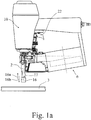
- the driving tool shown in the drawings serves to drive in fasteners 1 on a cartridge belt 4, in particular nails, staples or the like.
- fasteners 1 on a cartridge belt 4, in particular nails, staples or the like.
- fastener the focus is on driving in nails, which should not be understood as limiting. All statements relating to nails apply correspondingly to all other types of fastener which can be driven in.
- the fasteners 1 are driven out of a driving channel 2 into a workpiece 3 which is to be nailed, in driving cycles.
- a driving piston is usually used to drive the nails in.
- the detail of the driving itself is not relevant for the proposed solution.
- a driving cycle is usually combined with a conveying cycle for the cartridge belt 4 along a conveying path.
- the cartridge belt 4 is conveyed along the conveying path to the driving channel 2 in a conveying direction 5.
- the cartridge belt 4 is here preferably a coil cartridge belt, wound up in a coil cartridge, that comprises a support belt 7 and the fasteners 1 themselves. All of the alternatives mentioned in the introductory part of the description can also be applied to the design of the cartridge belt 4.
- the driving tool takes the form of a hand tool and has a conventional structure. It is, however, also conceivable that the driving tool can be applied in conjunction with an automatic positioning unit such as a robot or the like.
- the fasteners 1 are "shot” and not “pushed” into the workpiece 3.
- the speed at which the nail enters the workpiece is not significant for the proposed solution.
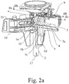
- the driving tool is equipped with a mechanical cartridge belt limit switch 8 that, as will be explained, senses at a sensing point 9 ( Figure 2c ) whether there is a cartridge belt 4 in the conveying path. After a cartridge belt is no longer present at the sensing point 9, following a conveying cycle, the cartridge belt limit switch 8 initiates the deactivation of the driving tool.
- a conveying cycle thus comprises the feeding of the cartridge belt 4 preferably by precisely one cartridge place equipped with a fastener 1.
- the driving of the fastener 1a shown in Figure 2c results in the cartridge belt 4 no longer being present at the sensing point 9.
- the cartridge belt limit switch 8 still allows a last driving cycle to be carried out after a cartridge belt is no longer present at the sensing point 9. Only after this last driving cycle has been completed is the deactivation of the driving tool, which is still to be explained, initiated.
- the proposed solution enables the sensing point 9 to be positioned at a distance from the driving channel 2 which corresponds exactly to the feed travel of a conveying cycle.
- the sensing point 9 is advantageously placed along the conveying path such that all fasteners 1 of the respective cartridge belt 4 are driven in after the abovementioned last driving cycle or the abovementioned last group of driving cycles has been carried out.
- an in particular pneumatic drive means 10 is provided for driving in the fasteners 1, wherein a driving cycle here preferably results from a back-and-forth movement of a driving piston.
- an in particular pneumatic conveying drive means 11 is provided for conveying the fasteners 1 to the driving channel 2, wherein a conveying cycle here preferably results from a back-and-forth movement of a conveying piston 12.
- a conveying cycle is combined with a back-and-forth movement of a driver 13 in the conveying path, which with each conveying cycle comes into conveying engagement with the respective next section of the cartridge belt 4.
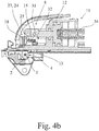
- the design of the driver 13 can be well understood, for example, by viewing Figures 2a and 4a .
- the driver 13 engages in recesses 7a in the support belt 7 and in a conveying cycle first executes a movement to the right in Figure 4a so that it comes into engagement with the next section of the cartridge belt 4, i.e. with the next recess 7a of the support belt 7.
- a catch 14 (only indicated in Figure 2a ) ensures that the cartridge belt 4 cannot follow the movement of the driver 13.
- the driver 13 then executes a return movement to the left in Figure 4a , which causes a conveying movement of the cartridge belt 4 to the left in Figure 4a .
- the driver 13 is a constituent of an extension arm 15 of the conveying piston 12 so that the back-and-forth movement of the driver 13 is effected by the conveying piston 12.
- the driving tool shown is, in a manner known per se, equipped with a workpiece contact 16 which is here preferably designed so that it can be displaced in the direction in which the driving channel 2 extends.
- the workpiece contact 16 is spring-tensioned and is depressed when the driving tool is placed on the workpiece 3 in such a way that the opening 17 of the driving channel 2 has a predetermined distance (which can here be adjusted) from the surface of the workpiece.
- the spring tensioning and the adjustability can be clearly understood from the above detailed view in Figure 1b .
- the workpiece contact 16 engages via a retaining plate 18 with a thread 19 which is pretensioned downwards by the spring 20 which is only indicated in Figure 1b .
- the maximum depth by which the contact can be depressed furthermore results from the construction shown in the above detailed description of Figure 1b .
- the possibility of adjusting the gap between the opening 17 of the driving channel 2 and the surface of the workpiece here preferably is a result of the thread 19 being rotatable about its axis by means of the actuating wheel 21. This adjustability plays an important role in the proposed solution in a way which will be explained later.
- the driving tool shown is equipped with a conventional, in particular pneumatic actuating element 22, here preferably an actuating trigger 22, for the user to initiate a driving cycle.
- the actuating element 22 is here coupled to the workpiece contact 16 in such a way that a driving cycle can be initiated by the actuating element 22 only when the workpiece contact 16 is depressed. This is an effective safety function to prevent a fastener 1 from being accidentally "shot out”.
- the blocking device 23 is associated with a toothed rack 24 for blocking engagement, wherein the toothed rack 24 extends at least on one side over a region along the direction 16a in which the workpiece contact 16 is depressed, so that the workpiece contact 16 can be blocked at different depressed depths.
- the toothed rack 24 can be seen best by comparing Figures 1b and 3 .
- the toothed rack 24 is designed in such a way that, when the blocking device 23 is actuated, it is ensured that the workpiece contact 16 rebounds in a rebound direction 16b which is opposite to the depression direction 16a.
- the toothed rack 24 here preferably consists of two sawtooth segments associated with each other.
- Figure 3 shows that the blocking device 23 has an actuatable blocking lever 25 which, in the actuated state shown in Figure 3 , comes or can be brought into blocking engagement with a blocking section 26 of the workpiece contact 16.
- the blocking lever 25 is thus pretensioned, here preferably in the direction of the unactuated position.
- the blocking lever 25 can be pretensioned in different ways.
- a leaf spring 27 is provided for the pretensioning, which is or can be brought into engagement with the blocking lever 25.
- any type of positive or non-positive connection between the blocking lever 25 and the blocking section 26 is in principle conceivable.
- the blockability is here preferably achieved by the abovementioned toothed rack, namely by corresponding tooth geometries on the blocking lever 25, on one hand, and on the blocking section 26 of the workpiece contact 16, on the other hand.
- the cartridge belt limit switch 8 is here advantageously coupled to the conveying drive means 11 in such a way that, when the cartridge belt is no longer present at the sensing point 9, a subsequent conveying cycle causes the deactivation of the driving tool, here preferably the blocking of the depression of the workpiece contact 16 by means of the blocking device 23.
- the conveying drive means 11 thus has a dual purpose, namely to convey the cartridge belt 4, on the one hand, and to deactivate the driving tool, on the other hand.
- the cartridge belt limit switch 8 preferably takes the form of a mechanical memory and can be brought into a reset mode ( Figure 4a ), a preset mode ( Figure 4b ) and a set mode ( Figure 4c ).
- This design as a mechanical memory allows the delayed deactivation of the driving tool explained above.
- a conveying cycle has no effect on the cartridge belt limit switch 8 and on the blocking device 23.
- a conveying cycle causes the transfer of the cartridge belt limit switch 8 into the set mode.
- the cartridge belt limit switch 8 in turn causes the deactivation of the driving tool, here the blocking of the depression of the workpiece contact 16 by means of the blocking device 23.
- the cartridge belt limit switch 8 When there is a cartridge belt at the sensing point 9, the cartridge belt limit switch 8 is always in reset mode. Immediately after there is no longer a cartridge belt present, the cartridge belt limit switch 8 is again in preset mode.
- the cartridge belt limit switch 8 has a control lever 28 which can here preferably pivot about a control lever axis 28a and can be brought into a reset mode (solid lines in Figure 2c ), into a preset mode (not shown), and into a set mode (dashed lines in Figure 2c ).
- the preset mode lies between the reset mode and the set mode, to be precise preferably next to the reset mode, as will become clear.
- the control lever 28 is spring-loaded into the conveying path by means of a spring 29. Moreover, the control lever 28 is equipped with a sensing nose 30 for the cartridge belt 4, by means of which the control lever 28 presses against the cartridge belt 4 in the situation shown in solid lines in Figure 2c , whereby the control lever 28 is held in reset mode. To clarify things, it must be pointed out that the control lever 28 is not designed to be level and instead has a whole series of different deformations, as also will become clear.
- control lever 28 moves from the reset mode to the preset mode when the cartridge belt is no longer present at the sensing point 9, which is here associated with a very slight pivoting movement of the control lever 28 to the left in Figure 2c .
- control lever 28 has a control lever coupling element 31, and that the conveying drive means 11, here the conveying piston 12, has a corresponding conveying drive means coupling element 32.
- the two coupling elements 31, 32 and hence the control lever 28 and the conveying drive means 11, here the conveying piston 12, are always disengaged so that the cartridge belt limit switch 8 has no effect on the operation of the driving tool.
- Figure 3 shows that the control lever coupling element 31 hereby acts on the leaf spring 27 of the blocking lever 25, pushing it to the right in Figure 3 .
- the control lever coupling element 31 preferably takes the form of a coupling carriage so that in the set mode the blocking device 23 can be actuated by means of the conveying drive means 11, in this case by means of the conveying piston 12, via the control lever coupling element 31, displacing the latter in the carriage guide.
- the coupling carriage is here preferably pretensioned by means of a coupling spring 33 into the undeflected position.
- the conveying drive means 11 is pretensioned by means of the spring 34 into its initial position, which here corresponds to a pretensioning of the conveying piston 12 in the direction of the return movement, the actuation of the blocking device 23 is maintained for the time being by the pretensioning of the conveying drive means 11.
- the transition of the cartridge belt limit switch 8 back into the reset mode is here achieved in a particularly interesting structural manner.
- the door 35 is used for this purpose and delimits at least a part of the conveying path situated upstream from the driving channel 2 and which needs to be opened in order to insert the cartridge belt 4.
- an opening lever 36 is provided which can be seen from viewing Figures 2a and 2b .
- the opening lever 36 is pretensioned to the right in Figure 2b by means of an opening lever spring 37 and is coupled or can be coupled to the door 35, on the one hand, and the control lever 28, on the other hand, in such a way that the opening lever 36 transfers the control lever 28 into the reset mode when the door 35 is opened.
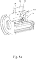
- Figure 5a shows the control lever coupling element 31 more or less separately from the other components. It can also be seen here that the carriage guide 31a of the control lever coupling element 31 is oriented substantially perpendicular to the control lever axis 28a. The movement of the carriage is here indicated by the reference numeral 38, and the pivoting of the control lever 28 by the reference numeral 39.
- Figure 5b shows, also in a view more or less separate from the other components, the conveying drive means 11 with the conveying drive means coupling element 32, which is arranged on the extension arm 15 of the conveying piston 12.
- a method for driving in fasteners 1 on a cartridge belt in driving cycles by means of a driving tool, in particular a driving tool as described above.
- a driving cycle is combined with a conveying cycle for the cartridge belt 4 along a conveying path, wherein a sensing point 9 in the conveying path senses the presence of the cartridge belt 4 and wherein, after the cartridge belt is no longer present at the sensing point 9 following a conveying cycle, deactivation of the driving tool is initiated.
- An essential part of this further teaching is that, after the cartridge belt is no longer present at the sensing point 9, a last driving cycle or a last group of driving cycles can be carried out, and the deactivation of the driving tool is initiated only after the last driving cycle or the last group of driving cycles has been completed.
Landscapes
- Engineering & Computer Science (AREA)
- Mechanical Engineering (AREA)
- Physics & Mathematics (AREA)
- Fluid Mechanics (AREA)
- Portable Nailing Machines And Staplers (AREA)
Claims (13)
- Eintreibvorrichtung zum Eintreiben von Befestigungselementen (1), insbesondere Nägeln oder Ösen, auf einem Patronengurt (4) in Eintreibzyklen aus einem Eintreibkanal (2), wobei ein Eintreibzyklus mit einem Zuführzyklus für den Patronengurt (4) entlang eines Zuführwegs kombiniert wird, wobei ein mechanischer Patronengurtgrenzschalter (8) vorgesehen ist, der an einem Erfassungspunkt (9) in dem Zuführweg erfasst, ob der Patronengurt (4) vorhanden ist, wobei der Patronengurtgrenzschalter (8) die Abschaltung der Eintreibvorrichtung auslöst, nachdem der Patronengurt nach einem Zuführzyklus nicht mehr an dem Erfassungspunkt (9) vorhanden ist,
dadurch gekennzeichnet, dass,
nachdem der Patronengurt nicht mehr an dem Erfassungspunkt (9) vorhanden ist, der Patronengurtgrenzschalter (8) noch die Durchführung eines letzten Eintreibzyklus oder einer letzten Gruppe von Eintreibzyklen ermöglicht und die Abschaltung der Eintreibvorrichtung erst nach Beendigung des letzten Eintreibzyklus oder der letzten Gruppe von Eintreibzyklen ausgelöst wird, wobei ein Zuführantriebsmittel (11) vorgesehen ist, um die Befestigungselemente (1) dem Eintreibkanal (2) zuzuführen, und der Patronengurtgrenzschalter (8) auf eine solche Weise an das Zuführantriebsmittel (11) gekoppelt ist, dass, wenn der Patronengurt nicht mehr an dem Erfassungspunkt (9) vorhanden ist, ein nachfolgender Zuführzyklus die Abschaltung der Eintreibvorrichtung bewirkt. - Eintreibvorrichtung nach Anspruch 1, dadurch gekennzeichnet, dass ein Zuführzyklus das Ergebnis einer Hin- und Herbewegung eines Antriebskolbens (12) ist.
- Eintreibvorrichtung nach Anspruch 1 oder 2, dadurch gekennzeichnet, dass ein Zuführzyklus mit einer Hin- und Herbewegung eines Ritzels (13) in dem Zuführweg kombiniert wird, mit dem jeder Zuführzyklus in einen Zuführeingriff mit dem entsprechenden nächsten Abschnitt des Patronengurts (4) gebracht wird.
- Eintreibvorrichtung nach einem der vorhergehenden Ansprüche, dadurch gekennzeichnet, dass ein Werkstückkontakt (16) vorgesehen ist, der in der Richtung, in der sich der Eintreibkanal (2) erstreckt, verschoben werden kann, wobei der Werkstückkontakt (16) niedergedrückt wird, wenn die Eintreibvorrichtung auf eine solche Weise auf das entsprechende Werkstück (3) gesetzt wird, dass die Öffnung (17) des Eintreibkanals (2) einen vorgegebenen Abstand von der Oberfläche des Werkstücks aufweist, vorzugsweise so, dass ein Betätigungselement (22) für den Benutzer vorgesehen ist, um einen Eintreibzyklus auszulösen, und so, dass das Betätigungselement (22) auf eine solche Weise an den Werkstückkontakt (16) gekoppelt ist, dass ein Eintreibzyklus nur dann durch das Betätigungselement (22) ausgelöst werden kann, wenn der Werkstückkontakt (16) niedergedrückt ist.
- Eintreibvorrichtung nach Anspruch 4, dadurch gekennzeichnet, dass die durch den Patronengurtgrenzschalter (8) ausgelöste Abschaltung der Eintreibvorrichtung dadurch erfolgt, dass das Niederdrücken des Werkstückkontakts (16) mit Hilfe einer betätigbaren Blockiervorrichtung (23) blockiert wird.
- Eintreibvorrichtung nach Anspruch 5, dadurch gekennzeichnet, dass die Blockiervorrichtung (23) für einen blockierenden Eingriff in Verbindung mit einer Zahnstange (24) steht und dass sich die Zahnstange (24) wenigstens auf einer Seite über einen Bereich entlang der Richtung (16a) erstreckt, in der der Werkstückkontakt (16) niedergedrückt wird, so dass der Werkstückkontakt (16) bei verschiedenen Niederdrücktiefen blockiert werden kann, vorzugsweise indem die Zahnstange (24) so ausgeführt ist, dass bei Betätigung der Blockiervorrichtung (23) ein Zurückspringen des Werkstückkontakts (16) möglich ist.
- Eintreibvorrichtung nach Anspruch 5 oder 6, dadurch gekennzeichnet, dass die Blockiervorrichtung (23) einen betätigbaren Blockierhebel (25) aufweist, der im betätigten Zustand in einen Blockiereingriff mit einem Blockierabschnitt (26) des Werkstückkontakts (16) kommt oder in diesen gebracht werden kann, und dass die Zahnstange (24) einerseits durch entsprechende Zahngeometrien auf dem Blockierhebel (25) und andererseits durch entsprechende Zahngeometrien auf dem Blockierabschnitt (26) des Werkstückkontakts (16) gebildet ist.
- Eintreibvorrichtung nach einem der vorhergehenden Ansprüche, dadurch gekennzeichnet, dass der Patronengurtgrenzschalter (8) auf eine solche Weise an das Zuführantriebsmittel (11) gekoppelt ist, dass, wenn der Patronengurt nicht mehr an dem Erfassungspunkt (9) vorhanden ist, ein nachfolgender Zuführzyklus die Abschaltung der Eintreibvorrichtung, d.h. die Blockierung des Niederdrückens des Werkstückkontakts (16) mit Hilfe der Blockiervorrichtung (23) bewirkt.
- Eintreibvorrichtung nach einem der vorhergehenden Ansprüche, dadurch gekennzeichnet, dass der Patronengurtgrenzschalter (8) in einen Rückstellmodus, einen Voreinstellmodus und einen Einstellmodus gebracht werden kann, dass in dem Rückstellmodus ein Zuführzyklus keine Auswirkung auf den Patronengurtgrenzschalter (8) und die möglicherweise vorhandene Blockiervorrichtung (23) hat, in dem Voreinstellmodus ein Zuführzyklus die Überführung des Patronengurtgrenzschalters (8) in den Einstellmodus bewirkt und in dem Einstellmodus der Patronengurtgrenzschalter (8) die Abschaltung der Eintreibvorrichtung, insbesondere die Blockierung des Niederdrückens des Werkstückkontakts (16) mit Hilfe der Blockiervorrichtung (23) bewirkt.
- Eintreibvorrichtung nach Anspruch 9, dadurch gekennzeichnet, dass sich der Patronengurtgrenzschalter (8) in dem Rückstellmodus befindet, wenn der Patronengurt an dem Erfassungspunkt (9) vorhanden ist, und sich unmittelbar, nachdem der Patronengurt nicht mehr an dem Erfassungspunkt (9) vorhanden ist, in dem Voreinstellmodus befindet.
- Eintreibvorrichtung nach Anspruch 9 und möglicherweise nach Anspruch 10, dadurch gekennzeichnet, dass der Patronengurtgrenzschalter (8) einen Steuerhebel (28), der entsprechend in einen Rückstellmodus, in einen Voreinstellmodus und in einen Einstellmodus gebracht werden kann, vorzugsweise indem der Steuerhebel (28) in dem Zuführweg federbelastet wird, und eine Erfassungsnase (30) für den Patronengurt (4) aufweist, und dass bei normalem Betrieb der Steuerhebel (28) aus dem Rückstellmodus in den Voreinstellmodus geht, wenn der Patronengurt nicht mehr an dem Erfassungspunkt (9) vorhanden ist.
- Eintreibvorrichtung nach Anspruch 11, dadurch gekennzeichnet, dass der Steuerhebel (28) in dem Einstellmodus vorgespannt ist, in dem Voreinstellmodus an einem Einstellteil (32) des Zuführantriebsmittels (11) anliegt und in Folge der Bewegung des Zuführantriebsmittels (11) im Verlauf eines Zuführzyklus in den Einstellmodus geht.
- Verfahren zum Eintreiben von Befestigungselementen (1), insbesondere Nägeln oder Ösen, auf einem Patronengurt (4) in Eintreibzyklen mit Hilfe einer Eintreibvorrichtung, wobei ein Eintreibzyklus mit einem Zuführzyklus für den Patronengurt (4) entlang eines Zuführwegs kombiniert wird, wobei ein Erfassungspunkt (9) in dem Zuführweg erfasst, ob der Patronengurt (4) vorhanden ist, wobei die Abschaltung der Eintreibvorrichtung ausgelöst wird, nachdem der Patronengurt nach einem Zuführzyklus nicht mehr an dem Erfassungspunkt (9) vorhanden ist, dadurch gekennzeichnet, dass, nachdem der Patronengurt nicht mehr an dem Erfassungspunkt (9) vorhanden ist, ein letzter Eintreibzyklus oder eine letzte Gruppe von Eintreibzyklen durchgeführt werden kann und die Abschaltung der Eintreibvorrichtung erst nach Beendigung des letzten Eintreibzyklus oder der letzten Gruppe von Eintreibzyklen ausgelöst wird, wobei ein Zuführantriebsmittel (11) vorgesehen ist, um die Befestigungselemente (1) dem Eintreibkanal (2) zuzuführen, und der Patronengurtgrenzschalter (8) auf eine solche Weise an das Zuführantriebsmittel (11) gekoppelt ist, dass, wenn der Patronengurt nicht mehr an dem Erfassungspunkt (9) vorhanden ist, ein nachfolgender Zuführzyklus die Abschaltung der Eintreibvorrichtung bewirkt.
Applications Claiming Priority (2)
| Application Number | Priority Date | Filing Date | Title |
|---|---|---|---|
| DE201010054507 DE102010054507A1 (de) | 2010-12-14 | 2010-12-14 | Eintreibwerkzeug zum Eintreiben von Befestigungsmitteln eines Magazinbands |
| PCT/US2011/064824 WO2012082850A2 (en) | 2010-12-14 | 2011-12-14 | Driving tool for driving in fasteners on a cartridge belt |
Publications (2)
| Publication Number | Publication Date |
|---|---|
| EP2651605A2 EP2651605A2 (de) | 2013-10-23 |
| EP2651605B1 true EP2651605B1 (de) | 2017-07-26 |
Family
ID=45478500
Family Applications (1)
| Application Number | Title | Priority Date | Filing Date |
|---|---|---|---|
| EP11808443.3A Active EP2651605B1 (de) | 2010-12-14 | 2011-12-14 | Eintreibvorrichtung zum eintreiben von befestigungselementen auf einem patronengurt |
Country Status (5)
| Country | Link |
|---|---|
| EP (1) | EP2651605B1 (de) |
| DE (1) | DE102010054507A1 (de) |
| DK (1) | DK2651605T3 (de) |
| NO (1) | NO2651605T3 (de) |
| WO (1) | WO2012082850A2 (de) |
Families Citing this family (3)
| Publication number | Priority date | Publication date | Assignee | Title |
|---|---|---|---|---|
| CN113894902B (zh) * | 2020-12-08 | 2023-01-31 | 安徽信息工程学院 | 一种节能高效刻楦机 |
| DE112023000567T5 (de) | 2022-02-18 | 2025-01-30 | Milwaukee Electric Tool Corporation | Angetriebener befestigungsmitteleintreiber |
| DE102024112566A1 (de) | 2023-05-05 | 2024-11-07 | Milwaukee Electric Tool Corporation | Fremdkraftbetätigter befestigungsmitteleintreiber |
Family Cites Families (4)
| Publication number | Priority date | Publication date | Assignee | Title |
|---|---|---|---|---|
| US6966476B2 (en) | 2003-07-30 | 2005-11-22 | Stanley Fastening Systems, L.P. | Integrated check pawl, last nail-retaining, and dry fire lock-out mechanism for fastener-driving tool |
| JP4761257B2 (ja) * | 2006-09-12 | 2011-08-31 | 日立工機株式会社 | 留め具打込機 |
| US8104658B2 (en) * | 2007-11-20 | 2012-01-31 | De Poan Pneumatic Corp. | Block device for nail gun |
| US20100127035A1 (en) * | 2008-11-25 | 2010-05-27 | I-Tsung Wu | Braking Mechanism for Nail Guns |
-
2010
- 2010-12-14 DE DE201010054507 patent/DE102010054507A1/de not_active Withdrawn
-
2011
- 2011-12-14 DK DK11808443.3T patent/DK2651605T3/en active
- 2011-12-14 NO NO11808443A patent/NO2651605T3/no unknown
- 2011-12-14 EP EP11808443.3A patent/EP2651605B1/de active Active
- 2011-12-14 WO PCT/US2011/064824 patent/WO2012082850A2/en not_active Ceased
Non-Patent Citations (1)
| Title |
|---|
| None * |
Also Published As
| Publication number | Publication date |
|---|---|
| DK2651605T3 (en) | 2017-10-30 |
| WO2012082850A3 (en) | 2012-08-23 |
| DE102010054507A1 (de) | 2012-06-14 |
| NO2651605T3 (de) | 2017-12-23 |
| EP2651605A2 (de) | 2013-10-23 |
| WO2012082850A2 (en) | 2012-06-21 |
Similar Documents
| Publication | Publication Date | Title |
|---|---|---|
| EP0739690B1 (de) | Nagelmaschine mit Vorrichtung zur Führung von in Serie verbundenen Nägeln | |
| EP1882557B1 (de) | Schiebelager und Schiebeblock für eine Magazinzufuhrvorrichtung | |
| US7000294B2 (en) | Fastener driving tools | |
| US5240161A (en) | Fastener guide mechanism in fastener driving tool | |
| CA2795722C (en) | Fastener feeder delay for fastener driving tool | |
| KR100626980B1 (ko) | 전동 호치키스 | |
| EP2781307B1 (de) | Betätigungssperre für ein Befestigungsmitteleintreibwerkzeug | |
| AU2007250136B2 (en) | Fastener-driving tool having trigger control mechanism for alternatively permitting bump firing and sequential firing modes of operation | |
| AU2008276314B2 (en) | Actuator pin guide for a fastener driving tool | |
| EP1795305B1 (de) | Vorrichtungen zum Verhindern eines Leersetzganges für Setzgeräte und Setzgeräte ausgestattet mit solchen Vorrichtungen | |
| US5799856A (en) | Fastener driving tool | |
| KR960703053A (ko) | 수동 분리부를 구비한 전방 작동식 체결 장치(forward acting, staple machine with passive release) | |
| CN111673853A (zh) | 一种n形钉的自动钉枪 | |
| US5332141A (en) | Nailing machine | |
| EP2651605B1 (de) | Eintreibvorrichtung zum eintreiben von befestigungselementen auf einem patronengurt | |
| US7571840B2 (en) | Safety of nailing device | |
| NZ524870A (en) | Magazine rail system for fastener-driving tool | |
| US20220274236A1 (en) | Slap hammer with cap dispenser | |
| JP7155873B2 (ja) | 打ち込み工具 | |
| JP7795644B2 (ja) | 締結具駆動工具用のマガジン締結具ガイド | |
| CN215392300U (zh) | 一种自动上钉机构及具有该上钉机构的拉钉枪 | |
| KR100722208B1 (ko) | 스테플러 | |
| WO2024142732A1 (ja) | 作業機 | |
| JPH0546853Y2 (de) | ||
| US20080237293A1 (en) | Stapler |
Legal Events
| Date | Code | Title | Description |
|---|---|---|---|
| PUAI | Public reference made under article 153(3) epc to a published international application that has entered the european phase |
Free format text: ORIGINAL CODE: 0009012 |
|
| 17P | Request for examination filed |
Effective date: 20130715 |
|
| AK | Designated contracting states |
Kind code of ref document: A2 Designated state(s): AL AT BE BG CH CY CZ DE DK EE ES FI FR GB GR HR HU IE IS IT LI LT LU LV MC MK MT NL NO PL PT RO RS SE SI SK SM TR |
|
| RIN1 | Information on inventor provided before grant (corrected) |
Inventor name: HAEHNDEL, OLAF |
|
| DAX | Request for extension of the european patent (deleted) | ||
| RAP1 | Party data changed (applicant data changed or rights of an application transferred) |
Owner name: ILLINOIS TOOL WORKS INC. |
|
| 17Q | First examination report despatched |
Effective date: 20151023 |
|
| GRAP | Despatch of communication of intention to grant a patent |
Free format text: ORIGINAL CODE: EPIDOSNIGR1 |
|
| INTG | Intention to grant announced |
Effective date: 20170328 |
|
| GRAS | Grant fee paid |
Free format text: ORIGINAL CODE: EPIDOSNIGR3 |
|
| GRAA | (expected) grant |
Free format text: ORIGINAL CODE: 0009210 |
|
| AK | Designated contracting states |
Kind code of ref document: B1 Designated state(s): AL AT BE BG CH CY CZ DE DK EE ES FI FR GB GR HR HU IE IS IT LI LT LU LV MC MK MT NL NO PL PT RO RS SE SI SK SM TR |
|
| REG | Reference to a national code |
Ref country code: GB Ref legal event code: FG4D |
|
| REG | Reference to a national code |
Ref country code: CH Ref legal event code: EP |
|
| REG | Reference to a national code |
Ref country code: AT Ref legal event code: REF Ref document number: 911993 Country of ref document: AT Kind code of ref document: T Effective date: 20170815 |
|
| REG | Reference to a national code |
Ref country code: IE Ref legal event code: FG4D |
|
| REG | Reference to a national code |
Ref country code: DE Ref legal event code: R096 Ref document number: 602011039999 Country of ref document: DE |
|
| REG | Reference to a national code |
Ref country code: DK Ref legal event code: T3 Effective date: 20171024 |
|
| REG | Reference to a national code |
Ref country code: NL Ref legal event code: FP |
|
| REG | Reference to a national code |
Ref country code: LT Ref legal event code: MG4D |
|
| REG | Reference to a national code |
Ref country code: AT Ref legal event code: MK05 Ref document number: 911993 Country of ref document: AT Kind code of ref document: T Effective date: 20170726 |
|
| REG | Reference to a national code |
Ref country code: FR Ref legal event code: PLFP Year of fee payment: 7 |
|
| REG | Reference to a national code |
Ref country code: NO Ref legal event code: T2 Effective date: 20170726 |
|
| PG25 | Lapsed in a contracting state [announced via postgrant information from national office to epo] |
Ref country code: AT Free format text: LAPSE BECAUSE OF FAILURE TO SUBMIT A TRANSLATION OF THE DESCRIPTION OR TO PAY THE FEE WITHIN THE PRESCRIBED TIME-LIMIT Effective date: 20170726 Ref country code: LT Free format text: LAPSE BECAUSE OF FAILURE TO SUBMIT A TRANSLATION OF THE DESCRIPTION OR TO PAY THE FEE WITHIN THE PRESCRIBED TIME-LIMIT Effective date: 20170726 Ref country code: SE Free format text: LAPSE BECAUSE OF FAILURE TO SUBMIT A TRANSLATION OF THE DESCRIPTION OR TO PAY THE FEE WITHIN THE PRESCRIBED TIME-LIMIT Effective date: 20170726 Ref country code: HR Free format text: LAPSE BECAUSE OF FAILURE TO SUBMIT A TRANSLATION OF THE DESCRIPTION OR TO PAY THE FEE WITHIN THE PRESCRIBED TIME-LIMIT Effective date: 20170726 |
|
| PG25 | Lapsed in a contracting state [announced via postgrant information from national office to epo] |
Ref country code: PL Free format text: LAPSE BECAUSE OF FAILURE TO SUBMIT A TRANSLATION OF THE DESCRIPTION OR TO PAY THE FEE WITHIN THE PRESCRIBED TIME-LIMIT Effective date: 20170726 Ref country code: IS Free format text: LAPSE BECAUSE OF FAILURE TO SUBMIT A TRANSLATION OF THE DESCRIPTION OR TO PAY THE FEE WITHIN THE PRESCRIBED TIME-LIMIT Effective date: 20171126 Ref country code: RS Free format text: LAPSE BECAUSE OF FAILURE TO SUBMIT A TRANSLATION OF THE DESCRIPTION OR TO PAY THE FEE WITHIN THE PRESCRIBED TIME-LIMIT Effective date: 20170726 Ref country code: ES Free format text: LAPSE BECAUSE OF FAILURE TO SUBMIT A TRANSLATION OF THE DESCRIPTION OR TO PAY THE FEE WITHIN THE PRESCRIBED TIME-LIMIT Effective date: 20170726 Ref country code: LV Free format text: LAPSE BECAUSE OF FAILURE TO SUBMIT A TRANSLATION OF THE DESCRIPTION OR TO PAY THE FEE WITHIN THE PRESCRIBED TIME-LIMIT Effective date: 20170726 Ref country code: BG Free format text: LAPSE BECAUSE OF FAILURE TO SUBMIT A TRANSLATION OF THE DESCRIPTION OR TO PAY THE FEE WITHIN THE PRESCRIBED TIME-LIMIT Effective date: 20171026 Ref country code: GR Free format text: LAPSE BECAUSE OF FAILURE TO SUBMIT A TRANSLATION OF THE DESCRIPTION OR TO PAY THE FEE WITHIN THE PRESCRIBED TIME-LIMIT Effective date: 20171027 |
|
| PG25 | Lapsed in a contracting state [announced via postgrant information from national office to epo] |
Ref country code: RO Free format text: LAPSE BECAUSE OF FAILURE TO SUBMIT A TRANSLATION OF THE DESCRIPTION OR TO PAY THE FEE WITHIN THE PRESCRIBED TIME-LIMIT Effective date: 20170726 Ref country code: CZ Free format text: LAPSE BECAUSE OF FAILURE TO SUBMIT A TRANSLATION OF THE DESCRIPTION OR TO PAY THE FEE WITHIN THE PRESCRIBED TIME-LIMIT Effective date: 20170726 |
|
| REG | Reference to a national code |
Ref country code: DE Ref legal event code: R097 Ref document number: 602011039999 Country of ref document: DE |
|
| PG25 | Lapsed in a contracting state [announced via postgrant information from national office to epo] |
Ref country code: IT Free format text: LAPSE BECAUSE OF FAILURE TO SUBMIT A TRANSLATION OF THE DESCRIPTION OR TO PAY THE FEE WITHIN THE PRESCRIBED TIME-LIMIT Effective date: 20170726 Ref country code: EE Free format text: LAPSE BECAUSE OF FAILURE TO SUBMIT A TRANSLATION OF THE DESCRIPTION OR TO PAY THE FEE WITHIN THE PRESCRIBED TIME-LIMIT Effective date: 20170726 Ref country code: SK Free format text: LAPSE BECAUSE OF FAILURE TO SUBMIT A TRANSLATION OF THE DESCRIPTION OR TO PAY THE FEE WITHIN THE PRESCRIBED TIME-LIMIT Effective date: 20170726 Ref country code: SM Free format text: LAPSE BECAUSE OF FAILURE TO SUBMIT A TRANSLATION OF THE DESCRIPTION OR TO PAY THE FEE WITHIN THE PRESCRIBED TIME-LIMIT Effective date: 20170726 |
|
| PLBE | No opposition filed within time limit |
Free format text: ORIGINAL CODE: 0009261 |
|
| STAA | Information on the status of an ep patent application or granted ep patent |
Free format text: STATUS: NO OPPOSITION FILED WITHIN TIME LIMIT |
|
| 26N | No opposition filed |
Effective date: 20180430 |
|
| REG | Reference to a national code |
Ref country code: CH Ref legal event code: PL |
|
| GBPC | Gb: european patent ceased through non-payment of renewal fee |
Effective date: 20171214 |
|
| PG25 | Lapsed in a contracting state [announced via postgrant information from national office to epo] |
Ref country code: SI Free format text: LAPSE BECAUSE OF FAILURE TO SUBMIT A TRANSLATION OF THE DESCRIPTION OR TO PAY THE FEE WITHIN THE PRESCRIBED TIME-LIMIT Effective date: 20170726 |
|
| REG | Reference to a national code |
Ref country code: IE Ref legal event code: MM4A |
|
| PG25 | Lapsed in a contracting state [announced via postgrant information from national office to epo] |
Ref country code: LU Free format text: LAPSE BECAUSE OF NON-PAYMENT OF DUE FEES Effective date: 20171214 Ref country code: MT Free format text: LAPSE BECAUSE OF NON-PAYMENT OF DUE FEES Effective date: 20171214 |
|
| REG | Reference to a national code |
Ref country code: BE Ref legal event code: MM Effective date: 20171231 |
|
| PG25 | Lapsed in a contracting state [announced via postgrant information from national office to epo] |
Ref country code: IE Free format text: LAPSE BECAUSE OF NON-PAYMENT OF DUE FEES Effective date: 20171214 |
|
| PG25 | Lapsed in a contracting state [announced via postgrant information from national office to epo] |
Ref country code: BE Free format text: LAPSE BECAUSE OF NON-PAYMENT OF DUE FEES Effective date: 20171231 Ref country code: CH Free format text: LAPSE BECAUSE OF NON-PAYMENT OF DUE FEES Effective date: 20171231 Ref country code: LI Free format text: LAPSE BECAUSE OF NON-PAYMENT OF DUE FEES Effective date: 20171231 Ref country code: GB Free format text: LAPSE BECAUSE OF NON-PAYMENT OF DUE FEES Effective date: 20171214 |
|
| PG25 | Lapsed in a contracting state [announced via postgrant information from national office to epo] |
Ref country code: HU Free format text: LAPSE BECAUSE OF FAILURE TO SUBMIT A TRANSLATION OF THE DESCRIPTION OR TO PAY THE FEE WITHIN THE PRESCRIBED TIME-LIMIT; INVALID AB INITIO Effective date: 20111214 Ref country code: MC Free format text: LAPSE BECAUSE OF FAILURE TO SUBMIT A TRANSLATION OF THE DESCRIPTION OR TO PAY THE FEE WITHIN THE PRESCRIBED TIME-LIMIT Effective date: 20170726 |
|
| PG25 | Lapsed in a contracting state [announced via postgrant information from national office to epo] |
Ref country code: CY Free format text: LAPSE BECAUSE OF NON-PAYMENT OF DUE FEES Effective date: 20170726 |
|
| PG25 | Lapsed in a contracting state [announced via postgrant information from national office to epo] |
Ref country code: MK Free format text: LAPSE BECAUSE OF FAILURE TO SUBMIT A TRANSLATION OF THE DESCRIPTION OR TO PAY THE FEE WITHIN THE PRESCRIBED TIME-LIMIT Effective date: 20170726 |
|
| PG25 | Lapsed in a contracting state [announced via postgrant information from national office to epo] |
Ref country code: TR Free format text: LAPSE BECAUSE OF FAILURE TO SUBMIT A TRANSLATION OF THE DESCRIPTION OR TO PAY THE FEE WITHIN THE PRESCRIBED TIME-LIMIT Effective date: 20170726 |
|
| PG25 | Lapsed in a contracting state [announced via postgrant information from national office to epo] |
Ref country code: PT Free format text: LAPSE BECAUSE OF FAILURE TO SUBMIT A TRANSLATION OF THE DESCRIPTION OR TO PAY THE FEE WITHIN THE PRESCRIBED TIME-LIMIT Effective date: 20170726 |
|
| PG25 | Lapsed in a contracting state [announced via postgrant information from national office to epo] |
Ref country code: AL Free format text: LAPSE BECAUSE OF FAILURE TO SUBMIT A TRANSLATION OF THE DESCRIPTION OR TO PAY THE FEE WITHIN THE PRESCRIBED TIME-LIMIT Effective date: 20170726 |
|
| P01 | Opt-out of the competence of the unified patent court (upc) registered |
Effective date: 20230606 |
|
| PGFP | Annual fee paid to national office [announced via postgrant information from national office to epo] |
Ref country code: DK Payment date: 20241226 Year of fee payment: 14 |
|
| PGFP | Annual fee paid to national office [announced via postgrant information from national office to epo] |
Ref country code: FI Payment date: 20241226 Year of fee payment: 14 Ref country code: NL Payment date: 20241226 Year of fee payment: 14 |
|
| PGFP | Annual fee paid to national office [announced via postgrant information from national office to epo] |
Ref country code: NO Payment date: 20241230 Year of fee payment: 14 |
|
| PGFP | Annual fee paid to national office [announced via postgrant information from national office to epo] |
Ref country code: FR Payment date: 20251226 Year of fee payment: 15 |
|
| PGFP | Annual fee paid to national office [announced via postgrant information from national office to epo] |
Ref country code: DE Payment date: 20251229 Year of fee payment: 15 |