EP2651625B1 - Verbundwerkstoff mit fasern mit ineinandergreifenden formen und verfahren zu seiner herstellung - Google Patents
Verbundwerkstoff mit fasern mit ineinandergreifenden formen und verfahren zu seiner herstellung Download PDFInfo
- Publication number
- EP2651625B1 EP2651625B1 EP11788697.8A EP11788697A EP2651625B1 EP 2651625 B1 EP2651625 B1 EP 2651625B1 EP 11788697 A EP11788697 A EP 11788697A EP 2651625 B1 EP2651625 B1 EP 2651625B1
- Authority
- EP
- European Patent Office
- Prior art keywords
- fibers
- fiber
- notch
- composite article
- notch region
- Prior art date
- Legal status (The legal status is an assumption and is not a legal conclusion. Google has not performed a legal analysis and makes no representation as to the accuracy of the status listed.)
- Active
Links
Images



Classifications
-
- F—MECHANICAL ENGINEERING; LIGHTING; HEATING; WEAPONS; BLASTING
- F41—WEAPONS
- F41H—ARMOUR; ARMOURED TURRETS; ARMOURED OR ARMED VEHICLES; MEANS OF ATTACK OR DEFENCE, e.g. CAMOUFLAGE, IN GENERAL
- F41H5/00—Armour; Armour plates
- F41H5/02—Plate construction
- F41H5/04—Plate construction composed of more than one layer
-
- B—PERFORMING OPERATIONS; TRANSPORTING
- B29—WORKING OF PLASTICS; WORKING OF SUBSTANCES IN A PLASTIC STATE IN GENERAL
- B29C—SHAPING OR JOINING OF PLASTICS; SHAPING OF MATERIAL IN A PLASTIC STATE, NOT OTHERWISE PROVIDED FOR; AFTER-TREATMENT OF THE SHAPED PRODUCTS, e.g. REPAIRING
- B29C70/00—Shaping composites, i.e. plastics material comprising reinforcements, fillers or preformed parts, e.g. inserts
- B29C70/04—Shaping composites, i.e. plastics material comprising reinforcements, fillers or preformed parts, e.g. inserts comprising reinforcements only, e.g. self-reinforcing plastics
- B29C70/26—Non-fibrous reinforcements only
-
- F—MECHANICAL ENGINEERING; LIGHTING; HEATING; WEAPONS; BLASTING
- F41—WEAPONS
- F41H—ARMOUR; ARMOURED TURRETS; ARMOURED OR ARMED VEHICLES; MEANS OF ATTACK OR DEFENCE, e.g. CAMOUFLAGE, IN GENERAL
- F41H5/00—Armour; Armour plates
- F41H5/02—Plate construction
- F41H5/04—Plate construction composed of more than one layer
- F41H5/0442—Layered armour containing metal
- F41H5/0457—Metal layers in combination with additional layers made of fibres, fabrics or plastics
-
- F—MECHANICAL ENGINEERING; LIGHTING; HEATING; WEAPONS; BLASTING
- F41—WEAPONS
- F41H—ARMOUR; ARMOURED TURRETS; ARMOURED OR ARMED VEHICLES; MEANS OF ATTACK OR DEFENCE, e.g. CAMOUFLAGE, IN GENERAL
- F41H5/00—Armour; Armour plates
- F41H5/02—Plate construction
- F41H5/04—Plate construction composed of more than one layer
- F41H5/0471—Layered armour containing fibre- or fabric-reinforced layers
- F41H5/0478—Fibre- or fabric-reinforced layers in combination with plastics layers
-
- B—PERFORMING OPERATIONS; TRANSPORTING
- B29—WORKING OF PLASTICS; WORKING OF SUBSTANCES IN A PLASTIC STATE IN GENERAL
- B29K—INDEXING SCHEME ASSOCIATED WITH SUBCLASSES B29B, B29C OR B29D, RELATING TO MOULDING MATERIALS OR TO MATERIALS FOR MOULDS, REINFORCEMENTS, FILLERS OR PREFORMED PARTS, e.g. INSERTS
- B29K2995/00—Properties of moulding materials, reinforcements, fillers, preformed parts or moulds
- B29K2995/0037—Other properties
- B29K2995/0089—Impact strength or toughness
-
- B—PERFORMING OPERATIONS; TRANSPORTING
- B29—WORKING OF PLASTICS; WORKING OF SUBSTANCES IN A PLASTIC STATE IN GENERAL
- B29L—INDEXING SCHEME ASSOCIATED WITH SUBCLASS B29C, RELATING TO PARTICULAR ARTICLES
- B29L2031/00—Other particular articles
- B29L2031/768—Protective equipment
-
- Y—GENERAL TAGGING OF NEW TECHNOLOGICAL DEVELOPMENTS; GENERAL TAGGING OF CROSS-SECTIONAL TECHNOLOGIES SPANNING OVER SEVERAL SECTIONS OF THE IPC; TECHNICAL SUBJECTS COVERED BY FORMER USPC CROSS-REFERENCE ART COLLECTIONS [XRACs] AND DIGESTS
- Y10—TECHNICAL SUBJECTS COVERED BY FORMER USPC
- Y10T—TECHNICAL SUBJECTS COVERED BY FORMER US CLASSIFICATION
- Y10T29/00—Metal working
- Y10T29/49—Method of mechanical manufacture
- Y10T29/49801—Shaping fiber or fibered material
-
- Y—GENERAL TAGGING OF NEW TECHNOLOGICAL DEVELOPMENTS; GENERAL TAGGING OF CROSS-SECTIONAL TECHNOLOGIES SPANNING OVER SEVERAL SECTIONS OF THE IPC; TECHNICAL SUBJECTS COVERED BY FORMER USPC CROSS-REFERENCE ART COLLECTIONS [XRACs] AND DIGESTS
- Y10—TECHNICAL SUBJECTS COVERED BY FORMER USPC
- Y10T—TECHNICAL SUBJECTS COVERED BY FORMER US CLASSIFICATION
- Y10T428/00—Stock material or miscellaneous articles
- Y10T428/24—Structurally defined web or sheet [e.g., overall dimension, etc.]
-
- Y—GENERAL TAGGING OF NEW TECHNOLOGICAL DEVELOPMENTS; GENERAL TAGGING OF CROSS-SECTIONAL TECHNOLOGIES SPANNING OVER SEVERAL SECTIONS OF THE IPC; TECHNICAL SUBJECTS COVERED BY FORMER USPC CROSS-REFERENCE ART COLLECTIONS [XRACs] AND DIGESTS
- Y10—TECHNICAL SUBJECTS COVERED BY FORMER USPC
- Y10T—TECHNICAL SUBJECTS COVERED BY FORMER US CLASSIFICATION
- Y10T428/00—Stock material or miscellaneous articles
- Y10T428/24—Structurally defined web or sheet [e.g., overall dimension, etc.]
- Y10T428/24008—Structurally defined web or sheet [e.g., overall dimension, etc.] including fastener for attaching to external surface
-
- Y—GENERAL TAGGING OF NEW TECHNOLOGICAL DEVELOPMENTS; GENERAL TAGGING OF CROSS-SECTIONAL TECHNOLOGIES SPANNING OVER SEVERAL SECTIONS OF THE IPC; TECHNICAL SUBJECTS COVERED BY FORMER USPC CROSS-REFERENCE ART COLLECTIONS [XRACs] AND DIGESTS
- Y10—TECHNICAL SUBJECTS COVERED BY FORMER USPC
- Y10T—TECHNICAL SUBJECTS COVERED BY FORMER US CLASSIFICATION
- Y10T428/00—Stock material or miscellaneous articles
- Y10T428/24—Structurally defined web or sheet [e.g., overall dimension, etc.]
- Y10T428/24058—Structurally defined web or sheet [e.g., overall dimension, etc.] including grain, strips, or filamentary elements in respective layers or components in angular relation
-
- Y—GENERAL TAGGING OF NEW TECHNOLOGICAL DEVELOPMENTS; GENERAL TAGGING OF CROSS-SECTIONAL TECHNOLOGIES SPANNING OVER SEVERAL SECTIONS OF THE IPC; TECHNICAL SUBJECTS COVERED BY FORMER USPC CROSS-REFERENCE ART COLLECTIONS [XRACs] AND DIGESTS
- Y10—TECHNICAL SUBJECTS COVERED BY FORMER USPC
- Y10T—TECHNICAL SUBJECTS COVERED BY FORMER US CLASSIFICATION
- Y10T428/00—Stock material or miscellaneous articles
- Y10T428/24—Structurally defined web or sheet [e.g., overall dimension, etc.]
- Y10T428/24058—Structurally defined web or sheet [e.g., overall dimension, etc.] including grain, strips, or filamentary elements in respective layers or components in angular relation
- Y10T428/24124—Fibers
-
- Y—GENERAL TAGGING OF NEW TECHNOLOGICAL DEVELOPMENTS; GENERAL TAGGING OF CROSS-SECTIONAL TECHNOLOGIES SPANNING OVER SEVERAL SECTIONS OF THE IPC; TECHNICAL SUBJECTS COVERED BY FORMER USPC CROSS-REFERENCE ART COLLECTIONS [XRACs] AND DIGESTS
- Y10—TECHNICAL SUBJECTS COVERED BY FORMER USPC
- Y10T—TECHNICAL SUBJECTS COVERED BY FORMER US CLASSIFICATION
- Y10T428/00—Stock material or miscellaneous articles
- Y10T428/29—Coated or structually defined flake, particle, cell, strand, strand portion, rod, filament, macroscopic fiber or mass thereof
-
- Y—GENERAL TAGGING OF NEW TECHNOLOGICAL DEVELOPMENTS; GENERAL TAGGING OF CROSS-SECTIONAL TECHNOLOGIES SPANNING OVER SEVERAL SECTIONS OF THE IPC; TECHNICAL SUBJECTS COVERED BY FORMER USPC CROSS-REFERENCE ART COLLECTIONS [XRACs] AND DIGESTS
- Y10—TECHNICAL SUBJECTS COVERED BY FORMER USPC
- Y10T—TECHNICAL SUBJECTS COVERED BY FORMER US CLASSIFICATION
- Y10T428/00—Stock material or miscellaneous articles
- Y10T428/29—Coated or structually defined flake, particle, cell, strand, strand portion, rod, filament, macroscopic fiber or mass thereof
- Y10T428/2913—Rod, strand, filament or fiber
- Y10T428/2973—Particular cross section
- Y10T428/2978—Surface characteristic
Definitions
- the present disclosure relates generally to composites and, more particularly, to fiber reinforced composite articles having improved ballistic performance.
- Composite structures typically comprise a matrix reinforced with fibers wherein the fibers are embedded in the matrix. Composite structures are designed to transmit loads along the length of the fibers. Loads from one fiber may be transferred to another fiber in the same layer or to fibers in an adjacent layer by passing through the matrix material. However, the matrix is typically weaker than the fibers such that when a sufficiently high load is transmitted from one fiber to another fiber across the matrix, the matrix will fail. The failure of the matrix allows the fibers to move laterally within the composite structure.
- the ability of the fibers to move laterally or sideways is generally detrimental to the overall ballistic performance of the composite panel.
- the ability of the fibers in the matrix to move laterally allows the projectile to wedge between the fibers.
- the wedging of the projectile between the fibers allows the projectile to penetrate the thickness of a composite panel without fracturing the fibers.
- lateral movement of the fibers and subsequent wedging of a projectile reduces the ballistic performance capabilities of the panel.
- US2007/172677 discloses an impact resistant device comprising a flexible support matrix and a plurality of energy absorbing elements operatively connected to the support matrix. Each element comprises at least one ceramic material and at least one strain rate sensitive material.
- the impact resistant device can be worn as body armor to protect the wearer from high velocity projectiles.
- a composite article which includes a plurality of fibers at least partially embedded in a matrix.
- Each one of the fibers has upper, lower and side surfaces. At least one of the upper and lower surfaces of at least one of the fibers includes a notch region and a pair of side regions on opposite sides of the notch region.
- the plurality of fibers are arranged in layers. At least one of the fibers of one of the layers is received within the notch region of at least one of the fibers of another one of the layers.
- a fiber having upper, lower and side surfaces. At least one of the upper and lower surfaces may have a notch region and a pair of side regions on opposite sides of the notch region. The notch region may be configured to receive the side region of an adjacent fiber.
- the present disclosure additionally includes a method of manufacturing a composite article.
- the method includes the steps of forming a plurality of fibers with upper, lower and side surfaces.
- a notch region is formed in the fiber in at least one of the upper and lower surfaces of the fibers and extending axially along a length of the fiber.
- a pair of side regions are formed on opposite sides of the notch region. The notch region is configured to receive the side region of another one of the fibers.
- the method may additionally include receiving a pair of side regions of a corresponding pair of fibers within the notch region of one of the fibers.
- the plurality of fibers may be positioned in side-by- side arrangement such that the side surface of at least one of the fibers is substantially parallel to the side surface of an immediately adjacent one of the fibers.
- the method may include at least partially embedding the fibers in a matrix and curing or solidifying the matrix to form the composite article.
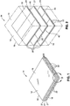
- FIG. 1 shown in Figure 1 is an embodiment of a composite article 10.
- the composite article 10 may be fabricated as a fiber-reinforced composite panel 14 comprising a matrix 18 and a plurality of fibers 22 embedded within the matrix 18.
- the matrix 18 may be formed of substantially optically transparent material.
- the fibers 22 may be formed of substantially optically transparent fiber 22 material.
- the composite article 10 is illustrated in Figure 1 in a panel 14 configuration having substantially planar panel surfaces 16, the composite article 10 may be provided in any one of a wide variety of sizes, shapes and configurations, without limitation, and may include planar surfaces and/or compound curvature surfaces.
- the composite article 10 as disclosed herein includes notch regions 40 ( Figure 2 ) extending axially along a length of the fibers 22 and enabling interlocking of the fibers 22 in a lateral or in-plane direction 46 ( Figures 4-10 ) and, optionally, enabling interlocking in an out-of-plane direction 48 ( Figures 6 , 8-10 ) as described below.
- the in-plane interlocking 46 of fibers 22 may restrict or prevent relative movement of at least one of the fibers 22 of one layer 20 with at least one of the fibers 22 of an adjacent layer 20.
- the interlocked fibers 22 of two different layers 20 comprise a coupled layer pair 21.
- the interlocking of the fibers 22 may improve the ballistic performance of the composite article 10 by preventing wedging of a projectile between the fibers 22.
- the interlocking of the fibers 22 may improve the optical quality of the composite article 10 by minimizing gaps between adjacent fibers 22.
- the addition of the notch regions 40 may advantageously improve and/or control the mechanical properties of the composite article 10 including improving properties such as interlaminar shear strength, stiffness, compression strength, fracture toughness and damage tolerance of the composite article 10.
- the optical performance of the composite article 10 may be improved by orienting the side surfaces 30 ( Figure 4 ) of the fibers 22 in non-perpendicular relation to the upper and lower surfaces 26, 28 ( Figure 4 ) of the fibers 22 to minimize the amount of light passing through the matrix 18 and between the fibers 22 otherwise resulting in a phase difference with the light passing through both the matrix 18 and the fibers 22 resulting in optical distortion.
- the composite article 10 formed as a panel 14 and including a plurality of the fibers 22 embedded within the matrix 18.
- the fibers 22 may function as structural reinforcement for the matrix 18 and may improve the mechanical and ballistic performance of the composite article 10.
- the fibers 22 provide structural reinforcing to improve the specific stiffness of the composite article 10 (i.e., the stiffness of the composite article 10 divided by the density thereof) as a result of the enhanced tensile strength and modulus of elasticity of the fibers 22.
- properties such as strength, strain and stiffness are in terms of dynamic properties and/or quasi-static properties.
- Ballistic performance may be improved due to the interlocking of the fibers 22 provided by the notch regions 40 ( Figure 2 ) formed in one or more of the fibers 22. More specifically, the notch regions 40 interlock the fibers 22 of one layer 20 with the fibers 22 of an adjacent layer 20 limiting the ability of the interlocked fibers 22 to move laterally relative to one another and relative to the matrix 18.
- the technical effect of the interlocking provided by the notch regions 40 is a reduction or elimination of wedging of a projectile between the fibers 22. During wedging, the projectile may undesirably push the fibers 22 laterally such that the projectile may pass between the fibers 22 allowing the projectile to penetrate the composite panel 14 without breaking the fibers 22.
- the present disclosure minimizes or reduces such lateral movement of the fibers 22 by interlocking the fibers 22 with the notch regions 40 formed in the fibers 22.
- the notch regions 40 result in an increase in energy required by the projectile to break the in-plane interlocking 46 ( Figures 4-10 ) that would otherwise facilitate lateral separation of fibers 22.
- the notch regions 40 may be configured to provide both in-plane and out-of-plane interlocking 46, 48 ( Figures 6 , 8-10 ) in certain configurations causing the fibers 22 to remain in close proximity to one another and resulting in a composite panel 14 having improved resistance to penetration such as from a projectile.
- the notch regions 40 may further provide improved damage resistance such that the composite article 10 may continue to carry structural loads following impact by a projectile.
- FIG. 2 shown is an exploded illustration of the composite article 10 or panel 14 of Figure 1 and illustrating a plurality of the fibers 22 formed as strips and arranged in layers 20 within the matrix 18.
- the fibers 22 are arranged in strips and are necessarily aligned with one another by virtue of the notch regions 40 extending along the length of each one of the fibers 22.
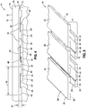
- Each one of the fibers 22 has an elongated cross-sectional shape that includes an opposed pair of substantially planar fiber surfaces 24 as best seen in Figure 4 .
- the fiber surfaces 24 such as the upper and lower surfaces 26, 28 ( Figure 4 ) may be oriented substantially parallel to the article surface 12 of the composite article 10 in order to enhance the optical performance of the composite article 10.
- the composite article 10 shown is an enlarged perspective illustration of the composite article 10 wherein the fibers 22 are arranged in layers 20 within the matrix 18.
- the layers 20 may be arranged in any orientation relative to one another within the composite article 10 and are not limited to the cross-ply configuration shown in Figure 3 .
- the composite article 10 in Figure 3 is illustrated as having six of the layers 20 of fibers 22 forming three coupled layer pairs 21 ( Figures 1-2 ), any quantity of layers 20 may be provided in any arrangement of interconnectivity.
- the composite article 10 may contain a single layer 20 of fibers 22 that may include notch regions 40 but which may not be interconnected to fibers 22 of another layer 20.
- the composite article 10 may include fibers 22 forming any number of coupled layer pairs 21.
- One or more of the coupled layer pairs 21 may be interconnected to one or more of the other coupled layer pairs 21 by means of the notch regions 40 formed in the upper and/or lower surfaces 26, 28 ( Figure 4 ) of one or more of the fibers 22.
- the composite article 10 may be comprised of a single layer 20 of fibers 22 or tens or more of the layers 20 of fibers 22.
- the layers 20 may be oriented in any direction relative to one another. More specifically, the fibers 22 in any layer 20 may be oriented at any angle relative to the fibers 22 of adjacent layers 20.
- Figure 3 illustrates several layers 20 each comprising fibers 22 interlocked with the fibers 22 of adjacent layers 20 via the notch regions 40.
- the layers 20 may comprise fibers 22 oriented in any direction relative to the fibers 22 of an immediately adjacent layer 20.
- Figure 3 illustrates a cross-ply configuration wherein the fibers 22 of one layer 20 of a coupled layer pair 21 are oriented perpendicularly relative to the fibers 22 of the immediately adjacent layer 20 of a coupled layer pair 21.
- Figure 3 is an illustration of a non-limiting embodiment of the composite article 10 and is not to be construed as limiting alternative configurations of the composite article 10 or alternative arrangements of the layers 20 of fibers 22 within the matrix 18.
- the layers 20 may be oriented in perpendicular orientation relative to one another as illustrated in Figure 3 or in any non-perpendicular orientation (e.g., 15°, 22.5°, 45°, 60°, 75°, etc.) relative to adjacent layers 20.
- each one of the fibers 22 has an elongated cross-sectional shape with relatively flattened or substantially planar fiber 22 faces to minimize bending or refracting of light that may otherwise occur when light passes through a curve surface.
- the substantially planar configuration of the fiber 22 improves the optical performance of the composite article 10.
- the generally elongated shape of the fibers 22 preferably have a relatively high aspect ratio.
- the aspect ratio may be defined as the ratio of fiber width 34 ( Figure 4 ) to fiber thickness 32 ( Figure 4 ).
- the aspect ratio may vary from approximately 3 to approximately 500 although the cross section of the fibers 22 may be provided in any aspect ratio.
- the fiber thickness 32 may be in the range of from approximately 5 microns to approximately 5,000 microns (e.g., 0.002 to 0.20 inch).
- the fiber 22 may be provided in any fiber thickness 32, without limitation.
- each one of the fibers 22 includes a notch region 40 extending axially along a length of the fiber 22.
- Figure 4 illustrates the notch region 40 formed in one of the upper and lower surfaces 26, 28 of each fiber 22, the fiber 22 may be provided in an embodiment wherein the notch regions 40 are formed in both the upper and lower surfaces 26, 28 of each fiber 22 as illustrated in Figures 7 and 9 and described in greater detail below.
- the notch region 40 for the fibers 22 may be generally centered within a width of the fiber 22. However, it is contemplated that the fibers 22 may be provided in configurations wherein the notch region 40 is biased toward one of the side surfaces 30 of the fibers 22.
- the notch region 40 in the upper surface 26 may be generally aligned with the notch region 40 in the lower surface 28 of the fiber 22 as described in greater detail below.
- the notch regions 40 in the upper and lower surfaces 26, 28 may be offset from one another.
- the notch region 40 may result in the fibers 22 having a thickness in the notch region 40 that is less than the fiber thickness 32 in the side regions 42.
- each one of the notch regions 40 has one of the side regions 42 disposed on opposite lateral sides of the notch region 40.
- the thickness of a fiber 22 in the notch region 40 is illustrated as being generally less than the thickness of the fiber 22 in the side regions 42.
- the fiber 22 may be provided in a configuration wherein the notch region 40 and side regions 42 have substantially similar thicknesses. In such a configuration (not shown), the fiber 22 may form a relatively shallow hat section as compared to the relatively shallow U-shaped sections formed by the configuration illustrated in Figures 4-5 .
- the notch region 40 may be bounded on opposed lateral sides by notch sidewalls 44.
- Figures 4 and 5 illustrate the notch sidewalls 44 as being oriented perpendicularly relative to the upper and lower surfaces 26, 28.
- Figures 6 , 8 and 9 illustrate notch sidewalls 44 formed at angles that are non-perpendicular relative to the upper and lower surfaces 26, 28.
- the fibers 22 may be configured such that the notch regions 40 including the side regions 42, side surfaces 30 and the notch sidewalls 44 may be formed with curved surfaces or a combination of planar surfaces and curved surfaces.
- the corners of the notch sidewalls 44 and side surfaces 30 may be rounded, beveled, chamfered or otherwise provided with non-sharp corners.
- the side regions 42 of one fiber 22 may be received within the notch region 40 of an adjacent one of the fibers 22 of the layer 20 to form a coupled layer pair 21.
- each notch region 40 may receive a pair of the side regions 42 of an adjacent pair of fibers 22 of an adjacent layer 20 as shown in Figure 4 .
- the fibers 22 are positioned in side-by-side arrangement and are retained to one another by means of the interlocking of the notch regions 40.
- the fibers 22 may be arranged such that the side surfaces 30 of the fibers 22 are preferably oriented substantially parallel to one another.
- Figure 4 illustrates the side surfaces 30 of each one of the fibers 22 being oriented parallel to one another and substantially perpendicularly relative to the upper and lower surfaces 26,28.
- Figures 6 and 7 illustrate the side surfaces 30 oriented substantially perpendicularly relative to the upper and lower surfaces 26, 28.
- Figure 6 illustrates the notch sidewalls 44 of each one of the notch regions 40 being oriented non-perpendicularly relative to the upper and lower surfaces 26, 28.
- Figure 6 illustrates a coupled layer pair 21 and representing a fiber 22 configuration providing in-plane interlocking 46 and out-of-plane interlocking 48 by virtue of the orientation of the notch sidewalls 44.
- FIG. 7 shown are the notch regions 40 wherein the notch sidewalls 44 are oriented substantially perpendicularly relative to the upper and lower surfaces 26, 28 such that the notch regions 40 provide in-plane interlocking 46 of the fibers 22.
- Figure 7 further illustrate the notch regions 40 formed in each one of the upper and lower surfaces 26, 28 of each one of the fibers 22 to provide a greater degree of in-plane interlocking 46 of adjacent fibers 22 than that which is provided by the single notch region 40 of the fibers 22 illustrated in Figures 4 and 5 .
- Figure 7 also illustrates the notch regions 40 formed in both the upper and lower surfaces 26, 28 of each one of the fibers 22 to facilitate interlocking of each fiber 22 to the fibers 22 of layers 20 located one each side of each fiber 22.
- Figure 7 illustrates two of the layers 20 interconnected to one another to form a coupled layer pair 21, the notch regions 40 on both upper and lower surfaces 26, 28 of the fibers 22 facilitates in-plane interconnection of additional layers 20 beyond the two layers 20 illustrated in Figure 7 .
- the side surfaces 30 of the fibers 22 are oriented non-perpendicularly relative to the upper and lower surfaces 26, 28 to provide out-of-plane interlocking 48 of the fibers 22.
- the side surfaces 30 may be oriented at any angle relative to the upper and lower surfaces 26, 28.
- the side surfaces 30 may be oriented between approximately 10° and 170° relative to the upper and lower surfaces 26, 28 although the side surfaces 30 may be oriented at angles less than 10 degrees or greater than 170 degrees relative to the upper and lower surfaces 26, 28.
- Figure 8 illustrates each fiber 22 having side surfaces 30 and notch sidewalls 44 oriented non-perpendicularly relative to the upper and lower surfaces 26, 28, the fibers 22 may be provided in a configuration where only the side surfaces 30 are oriented non-perpendicularly relative to the upper and lower surfaces 26, 28 and the notch sidewalls 44 are oriented substantially perpendicularly relative to the upper and lower surfaces 26, 28, or vice versa. It should also be noted that although the side surfaces 30 and notch sidewalls 44 are illustrated as being oriented at substantially the same angle relative to one another, the side surfaces 30 may be oriented at a different angle relative to the notch sidewalls 44.
- FIG 9 shown is an alternative embodiment of the fibers 22 illustrating the notch regions 40 of each fiber 22 being formed with notch sidewalls 44 having a non-perpendicular orientation relative to the upper and lower surfaces 26, 28 ( Figure 8 ).
- the side surfaces 30 of the fibers 22 may be formed at a non-perpendicular angle relative to the upper and lower surfaces 26, 28 to provide enhanced interlocking and resistance to movement of the fibers 22.
- Figure 9 also illustrates the notch regions 40 formed in both the upper and lower surfaces 26, 28 of each one of the fibers 22 to facilitate interlocking of each fiber 22 to the fibers 22 of layers 20 located on each side of each fiber 22 similar to that which is illustrated in Figure 7 and described above.
- Figure 9 illustrates three of the layers 20 having notch regions 40 on both upper and lower surfaces 26, 28 to facilitate interconnection thereof to form two of the coupled layer pairs 21.
- any quantity of layers 20 may be interconnected by means of the notch regions 40 on the upper and lower surfaces 26, 28 of each of the fibers 22.
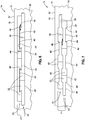
- Figure 10 shown is a sectional illustration of a portion of a composite article 10 comprising a stack of eight of the layers 20 of fibers 22 and forming four coupled layer pairs 21.
- the layers 20 of the coupled layer pairs 21 are oriented generally perpendicularly relative to the layers 20 of the adjacent coupled layer pairs 21.
- Figure 10 illustrates a cross-ply configuration of the layers 20 similar to the cross-ply configuration of the fibers 22 illustrated in Figures 2 and 3 . More particularly, Figure 10 illustrates two of the coupled layer pairs 21 extending out of the page and two of the coupled layer pairs 21 extending along the plane of the page.
- any quantity of layers 20 may be interconnected in any arrangement by providing notch regions 40 on one or more of the upper and/or lower surfaces 26, 28 of the fibers 22.
- matrix 18 material may be provided between each of the upper and lower surfaces 26, 28 of the fibers 22 including between the side surfaces 30 of adjacent fibers 22 and between the notch region 40 and notch sidewalls 44 of the adjacent fibers 22.
- the matrix 18 material may physically and optically couple the fibers 22 to one another.
- the fiber 22 arrangements resist separation in an in-plane direction.
- certain embodiments of the fibers 22 having angled notch sidewalls 44 as illustrated in Figures 6 , 8 and 9 may provide resistance against out-of-plane separation due to the non-perpendicular orientation of the notch sidewalls 44.
- the fibers 22 resist separation due to the interlocking effect which provides a means for controlling the amount of relative movement of the fibers 22 in the matrix 18 under different loading conditions.
- the fibers 22 may be desirable for the fibers 22 to resist in-plane separation while allowing other unconnected layers 20 of the fibers 22 to move relative to one another.
- the uppermost coupled layer pairs 21 may resist in-plane spreading of the fibers 22 (i.e., in the lateral direction) while the layers 20 immediately below the uppermost coupled layer pairs 21 may be unconnected to the uppermost coupled layer pairs 21 and may therefore move laterally relative to the layers 20 of the uppermost coupled layer pairs 21.
- Relative motion between pairs of layers 20 may be controlled by selection of the material properties of the matrix 18 and adhesive that may optionally be included for bonding the layers 20 together. For example, it may be desirable to select an adhesive that provides a limited degree of movement of the layers 20 relative to one another. Relative movement or slippage of certain fibers 22 within the matrix 18 may be desirable during a ballistic event such that a greater portion of the length of certain fibers 22 may contribute toward deceleration of a projectile.
- the fibers 22 and the matrix 18 may be formed of any suitable material which is preferably substantially optically transparent although the fibers 22 and/or matrix 18 may be formed of opaque materials.
- matrix 18 and/or the fibers 22 may be formed of any material having any degree of transparency between substantially transparent and substantially opaque.
- the matrix 18 and/or the fibers 22 may be formed of thermoplastic material and which may comprise at least one of the following: acrylics, fluorocarbons, polyamides, polyethylenes, polyesters, polypropylenes, polycarbonates, polyurethanes, polyetheretherketone, polyetherketoneketone, polyetherimides, epoxy and inorganic resins. Resins and oils may also be used for the matrix 18.
- the matrix 18 and/or the fibers 22 may also be formed of a thermosetting material comprising at least one of the following: polyurethanes, phenolics, polyimides, bismaleimides, polyesters, epoxy, and silsesquioxanes.
- the matrix 18 and/or the fibers 22 may be formed of inorganic materials including, but not limited to, carbons, silicon carbide, and boron.
- the matrix 18 and/or the fibers 22 may additionally be formed of glass such as E-glass (alumino-borosilicate glass), S-glass (alumino silicate glass), pure silica, borosilicate glass and optical glass.
- the fibers 22 may additionally be formed of metallic material.
- the composite article 10 ( Figures 1-10 ) as disclosed herein may be implemented in a variety of applications.
- the composite article 10 may be implemented as a ballistic panel 14 for a vehicular application such as for an aircraft windshield, canopy or window.
- the composite article 10 may be implemented in any non-vehicular application such as a membrane, a structural panel, an architectural panel, or a non-structural panel 14.
- the composite article 10 may be formed in any size, shape and configuration for any vehicular or non-vehicular application, without limitation.
- the composite article 10 is manufactured by forming a plurality of fibers 22 ( Figure 4 ) with upper, lower and side surfaces 26, 28, 30 ( Figure 4 ).
- the fibers 22 may be formed by extrusion, pultrusion or other suitable manufacturing process.
- the upper and lower surfaces 26, 28 may be formed to be substantially parallel to one another and are generally planar.
- the fibers 22 are formed in elongated cross-sectional shapes and may have an aspect ratio of fiber width 34 ( Figure 4 ) to fiber thickness 32 ( Figure 4 ) in the range of from approximately 3 to approximately 500 although other aspect ratios outside the 3-500 range are contemplated.
- the side surfaces 30 ( Figure 4 ) of the fibers 22 may be formed in substantially perpendicular relation to the upper and lower surfaces 26, 28 or in non-perpendicular relation to the upper and lower surfaces 26, 28 as shown in Figure 6 .
- the side surfaces 30 may be formed at any angle relative to the upper and lower surfaces 26, 28.
- the side surfaces 30 may be formed at an angle of between approximately 10° and 170° relative to at least one of the upper and lower surfaces 26, 28 although larger or smaller angles are contemplated.
- Step104 comprises forming a notch region 40 and a pair of side regions 42 on opposite lateral sides of the notch region 40 in the upper and/or lower surfaces 26, 28 of each one of the fibers 22 similar to that which is illustrated in Figures 4-9 .
- the notch region 40 may result in a thickness of the fiber 22 at the side regions 42 being greater than the fiber thickness 32 in the notch region 40.
- the notch regions 40 may be formed in both of the upper and lower surfaces 26, 28 and the notch regions 40 may be generally vertically aligned with one another as shown in Figure 7 and 9 although the notch regions 40 may be offset relative to one another.
- the notch region 40 may be generally centered within the width of the fiber 22 as shown in Figures 1-10 although the notch region 40 may be biased toward one of the side surfaces 30 of the fibers 22.
- the notch region 40 may include notch sidewalls 44 which may be formed at any angle relative to the upper and lower surfaces 26, 28.
- the notch regions 40 may be formed perpendicularly relative to the upper and lower surfaces 26, 28 as illustrated in Figures 4, 5 , and 7 .
- the notch sidewalls 44 may be formed at a non-perpendicular angle relative to the upper and lower surfaces 26, 28 similar to that which is illustrated in Figures 6 and 8-10 .
- Step 106 may comprise receiving a pair of the side regions 42 of a corresponding pair of fibers 22 within a notch region 40 of a fiber 22 to interconnect the fibers 22 as illustrated in Figures 6-10 .
- each one of the notch regions 40 accommodates a pair of the side regions 42 of a respective pair of fibers 22.
- Step 108 of the methodology of Figure 11 may comprise positioning a plurality of the fibers 22 in side-by-side relationship to one another such that the side surface 30 of at least one of the fibers 22 is oriented substantially parallel to the side surface 30 of an immediately adjacent one of the fibers 22.
- the fibers 22 are preferably configured such that the side surfaces 30 of adjacent fibers 22 are in close proximity to one another.
- the interconnected fibers 22 of one layer 20 may be oriented lengthwise at any angle relative to the lengthwise orientation of the fibers 22 of an adjacent layer 20.
- the layers 20 may be oriented substantially perpendicularly relative to the adjacent layers 20.
- a plurality of layers 20 having substantially parallel fibers 22 may be interconnected for embodiments including notch regions 40 in both the upper and lower surfaces 26, 28 of the fibers 22 similar to that which is illustrated in Figures 7 and 9 .
- layers 20 of fibers 22 that are oriented in non-perpendicular relation to one another may be interconnected by providing localized features (not shown) to engage the notch regions 40 extending axially along the fibers 22 of the adjacent layers 20.
- Step 110 may comprise at least partially embedding the fibers 22 in a matrix 18 similar to that which is illustrated in Figures 1-3 .
- the matrix 18 is preferably formed of substantially optically transparent material.
- the fibers 22 are preferably formed of substantially optically transparent material.
- Step 112 of Figure 11 may comprise curing or solidifying the matrix 18 and/or fibers 22 to form the composite article 10.
- the composite article 10 may be subjected to heat and/or pressure to facilitate curing or solidifying.
- One embodiment of the present invention relates to a composite article comprising a plurality of fibers (22) each having upper, lower and side surfaces, at least one of the upper and lower surfaces of at least one of the fibers having a notch region (40) and a pair of side regions (42) on opposite sides of the notch region (40), the plurality of fibers (22) being arranged in layers and at least one of the fibers of one of the layers being received within the notch region of at least one of the fibers of an adjacent one of the layers.
- the fiber (22) may have a thickness in the notch region (40) that is less than the fiber thickness in the side regions (42).
- the composite article may further comprise the plurality of fibers (22) positioned in side-by-side arrangement such that the side surface of at least one of the fibers is substantially parallel to the side surface of an immediately adjacent one of the fibers.
- the composite article may further comprise upper and lower surfaces each having a notch region (40) and the notch region in the upper surface of at least one fiber being generally aligned with the notch region in the lower surface of the fiber.
- the composite article may further comprise the notch region includes an opposing pair of notch sidewalls (44) and at least one of the notch sidewalls being oriented in non-perpendicular relation to at least one of the upper and lower surfaces of the fiber.
- the composite article may further comprise the fiber (22) has a cross section with an aspect ratio of fiber width to fiber thickness, and the aspect ratio being in the range of from approximately 3 to approximately 500.
- the composite article may further comprise wherein at least one of the matrix and the fiber is formed from at least one a thermoplastic material comprising at least one of the following: acrylics, fluorocarbons, polyamides, polyethylenes, polyesters, polypropylenes, polycarbonates, polyurethanes, polyetheretherketone, polyetherketoneketone, polyetherimides,a thermoset comprising at least one of the following: polyurethanes, phenolics, polyimides, bismaleimides, polyesters, epoxy, silsesquioxanes, inorganic materials comprising at least one of the following: carbons, silicon carbide, and boron; and glass comprising E-glass (alumino-borosilicate glass), S-glass (alumino silicate glass), pure silica, borosilicate glass, optical glass.
- Another embodiment of the present invention relates to a method of manufacturing a composite article, comprising, forming a plurality of fibers with upper, lower and side surfaces (102), forming a notch region and a pair of side regions on opposite sides of the notch region in at least one of the upper and lower surfaces of the fibers (104), receiving the side region of one of the fibers within the notch region of another one of the fibers.
- the method may further comprise, receiving a pair of side regions of a corresponding pair of fibers within the notch region (106).
- the method may further comprise, forming the notch region in both of the upper and lower surfaces.
- the method may further comprise, positioning a plurality of the fibers in side-by-side arrangement such that the side surface of at least one of the fibers is substantially parallel to the side surface of an immediately adjacent one of the fibers (105).
- the method may further comprise, forming notch sidewalls of the notch region at a non-perpendicular angle relative to at least one of the upper and lower surfaces of the fiber.
Landscapes
- Engineering & Computer Science (AREA)
- General Engineering & Computer Science (AREA)
- Ceramic Engineering (AREA)
- Chemical & Material Sciences (AREA)
- Composite Materials (AREA)
- Mechanical Engineering (AREA)
- Laminated Bodies (AREA)
- Aiming, Guidance, Guns With A Light Source, Armor, Camouflage, And Targets (AREA)
- Reinforced Plastic Materials (AREA)
- Moulding By Coating Moulds (AREA)
Claims (13)
- Verbundartikel, der aufweist:mehrere Fasern (22), die jeweils untere, obere (26, 28) und seitliche Flächen (30) aufweisen, wobei jede der mehreren Fasern (22) eine längliche Querschnittsform aufweist und wobei es sich bei der oberen und unteren Fläche um ein sich gegenüberliegendes Paar im Wesentlichen planarer Faseroberflächen (24) handelt;wobei die obere und/oder untere Fläche von zumindest einer der Fasern einen Nutenbereich (40) und zwei Seitenbereiche (42) an gegenüberliegenden Seiten des Nutenbereichs (40) aufweisen;wobei die mehreren Fasern (22) in Lagen angeordnet sind;wobei der Verbundartikel dadurch gekennzeichnet ist, dass:zumindest eine der Fasern von einer der Lagen innerhalb des Nutenbereichs (40) zumindest einer der Fasern einer der angrenzenden Lagen zur Bildung eines gekoppelten Lagenpaars (21) aufgenommen ist.
- Verbundartikel nach Anspruch 1, wobei:die Dicke der Faser (22) in dem Nutenbereich (40) kleiner als die Dicke der Faser in den Seitenbereichen (42) ist.
- Verbundartikel nach Anspruch 1 oder Anspruch 2, wobei:die mehreren Fasern (22) in einer Seite-an-Seite-Anordnung positioniert sind, sodass die seitliche Fläche (30) zumindest einer der Fasern in etwa parallel zur seitlichen Fläche einer unmittelbar benachbarten Faser ist.
- Verbundartikel nach einem der vorhergehenden Ansprüche, wobei:die obere und untere Fläche jeweils einen Nutenbereich (40) aufweist;und der Nutenbereich in der oberen Fläche von zumindest einer Faser generell mit dem Nutenbereich in der unteren Fläche der Faser ausgerichtet ist.
- Verbundartikel nach einem der vorhergehenden Ansprüche, wobei:der Nutenbereich ein Paar einander gegenüberliegender Nutenseitenwände (44) aufweist; undzumindest eine der Nutenseitenwände in einer nicht senkrechten Beziehung zu der oberen und/oder unteren Fläche der Faser orientiert ist.
- Verbundartikel nach einem der vorhergehenden Ansprüche, wobei:die Faser (22) einen Querschnitt mit einem Aspektverhältnis der Faserbreite zur Faserdicke aufweist, wobei das Aspektverhältnis im Bereich von etwa 3 bis etwa 500 liegt.
- Verbundartikel nach Anspruch 1, wobei die Matrix und/oder die Faser aus zumindest einem der folgenden Materialien gebildet ist:einem thermoplastischen Material, das zumindest einen der folgenden Stoffe umfasst: Acrylverbindungen, Fluorkohlenstoffe, Polyamide, Polyethylene, Polyester, Polypropylene, Polycarbonate, Polyurethane, Polyetheretherketon, Polyetherketonketon, Polyetherimide;einem Duroplasten, der zumindest einen der folgenden Stoffe umfasst: Polyurethane, Phenole, Polyimide, Bismaleimide, Polyester, Epoxide, Silsesquioxane;anorganischen Materialien, die zumindest einen der folgenden Stoffe umfassen: Kohlenstoffe, Siliciumcarbid und Bor; undGlas, wobei E-Glas (Aluminoborsilicatglas), S-Glas (Aluminosilicatglas), reines Siliciumoxid, Borsilicatglas, optisches Glas eingeschlossen sind.
- Verbundartikel nach einem der vorhergehenden Ansprüche, wobei der Verbundartikel als zumindest einer der folgenden Artikel ausgebildet ist:Windschutzscheibe, Überdachung, Fenster, Membran, tragendes Paneel, Bauplatte und nichttragender Artikel.
- Verfahren zur Herstellung eines Verbundartikels, das Schritte aufweist zum:Herstellen mehrerer Fasern mit unteren, oberen und seitliche Flächen (102), wobei jede der mehreren Fasern (22) eine längliche Querschnittsform aufweist und wobei es sich bei der oberen und unteren Fläche um ein sich gegenüberliegendes Paar im Wesentlichen planarer Faseroberflächen (24) handelt;Ausbilden eines Nutenbereichs (40) und von zwei Seitenbereichen (42) an gegenüberliegenden Seiten des Nutenbereichs in der oberen und/oder unteren Fläche der Fasern (104);Anordnen der mehreren Fasern (22) in Lagen (20); undAufnehmen des Seitenbereichs einer der Fasern in einer der Lagen innerhalb des Nutenbereichs einer anderen der Fasern einer der angrenzenden Lagen zur Bildung eines gekoppelten Lagenpaars (21).
- Verfahren nach Anspruch 9, das ferner einen Schritt aufweist zum:Aufnehmen eines Seitenbereichspaars eines entsprechenden Paars von Fasern innerhalb des Nutenbereichs (106).
- Verfahren nach Anspruch 9 oder Anspruch 10, das ferner einen Schritt aufweist zum:Ausbilden des Nutenbereichs sowohl in der oberen als auch in der unteren Fläche.
- Verfahren nach einem der Ansprüche 9 bis 11, das ferner einen Schritt aufweist zum:Positionieren mehrerer Fasern (22) in einer Seite-an-Seite-Anordnung, sodass die seitliche Fläche zumindest einer der Fasern in etwa parallel zur seitlichen Fläche einer unmittelbar benachbarten Faser (105) ist.
- Verfahren nach einem der Ansprüche 9 bis 12, das ferner einen Schritt aufweist zum:Ausbilden von Nutenseitenwänden des Nutenbereichs in einem nicht senkrechten Winkel zu der oberen und/oder unteren Fläche der Faser.
Applications Claiming Priority (2)
| Application Number | Priority Date | Filing Date | Title |
|---|---|---|---|
| US12/968,535 US8530027B2 (en) | 2010-12-15 | 2010-12-15 | Fibers with interlocking shapes |
| PCT/US2011/060062 WO2012082267A1 (en) | 2010-12-15 | 2011-11-09 | Composite material comprising fibers with interlocking shapes, and method to manufacture it |
Publications (2)
| Publication Number | Publication Date |
|---|---|
| EP2651625A1 EP2651625A1 (de) | 2013-10-23 |
| EP2651625B1 true EP2651625B1 (de) | 2017-01-04 |
Family
ID=45048259
Family Applications (1)
| Application Number | Title | Priority Date | Filing Date |
|---|---|---|---|
| EP11788697.8A Active EP2651625B1 (de) | 2010-12-15 | 2011-11-09 | Verbundwerkstoff mit fasern mit ineinandergreifenden formen und verfahren zu seiner herstellung |
Country Status (10)
| Country | Link |
|---|---|
| US (1) | US8530027B2 (de) |
| EP (1) | EP2651625B1 (de) |
| JP (1) | JP6055778B2 (de) |
| KR (1) | KR101902026B1 (de) |
| CN (1) | CN103269846B (de) |
| AU (1) | AU2011341611B2 (de) |
| CA (1) | CA2818343C (de) |
| ES (1) | ES2613676T3 (de) |
| RU (1) | RU2597375C2 (de) |
| WO (1) | WO2012082267A1 (de) |
Families Citing this family (13)
| Publication number | Priority date | Publication date | Assignee | Title |
|---|---|---|---|---|
| US8534018B2 (en) * | 2010-08-24 | 2013-09-17 | James Walker | Ventilated structural panels and method of construction with ventilated structural panels |
| US9604428B2 (en) | 2010-08-24 | 2017-03-28 | James Walker | Ventilated structural panels and method of construction with ventilated structural panels |
| US9050766B2 (en) | 2013-03-01 | 2015-06-09 | James Walker | Variations and methods of producing ventilated structural panels |
| US9091049B2 (en) | 2010-08-24 | 2015-07-28 | James Walker | Ventilated structural panels and method of construction with ventilated structural panels |
| US9242427B2 (en) | 2010-12-15 | 2016-01-26 | The Boeing Company | Coupled fibers in composite articles |
| US8790777B2 (en) * | 2012-04-19 | 2014-07-29 | The Boeing Company | Composite articles having fibers with longitudinally-varying geometry |
| US20130334366A1 (en) * | 2012-06-14 | 2013-12-19 | The Boeing Company | Formation of a shaped fiber with simultaneous matrix application |
| JP6023737B2 (ja) * | 2014-03-18 | 2016-11-09 | 信越化学工業株式会社 | ウエハ加工体、ウエハ加工用仮接着材、及び薄型ウエハの製造方法 |
| FR3056997B1 (fr) * | 2016-10-03 | 2021-09-17 | Leko France | Systeme constructif a lames structurelles croisees |
| US11852443B2 (en) | 2019-12-09 | 2023-12-26 | The Boeing Company | Ballistic panel and method of making a ballistic panel |
| US11719514B2 (en) | 2019-12-09 | 2023-08-08 | The Boeing Company | Ballistic panel and method of making a ballistic panel |
| DE102020111534B4 (de) | 2020-04-28 | 2025-11-06 | Knds Deutschland Gmbh & Co. Kg | Panzerung |
| CN113237387B (zh) * | 2021-05-10 | 2022-08-05 | 哈尔滨工业大学 | 一种包含互锁结构的抗弹铝基复合材料及其制备方法 |
Family Cites Families (12)
| Publication number | Priority date | Publication date | Assignee | Title |
|---|---|---|---|---|
| US5665450A (en) | 1992-08-21 | 1997-09-09 | The Curators Of The University Of Missouri | Optically transparent composite material and process for preparing same |
| US5788907A (en) | 1996-03-15 | 1998-08-04 | Clark-Schwebel, Inc. | Fabrics having improved ballistic performance and processes for making the same |
| US6641893B1 (en) | 1997-03-14 | 2003-11-04 | Massachusetts Institute Of Technology | Functionally-graded materials and the engineering of tribological resistance at surfaces |
| US5932315A (en) * | 1997-04-30 | 1999-08-03 | Hewlett-Packard Company | Microfluidic structure assembly with mating microfeatures |
| JPH11230696A (ja) * | 1997-12-09 | 1999-08-27 | Unitec Japan Kk | 身体防護纏い着 |
| DE69929913T2 (de) * | 1998-11-09 | 2006-08-03 | Pinnacle Armor, LLC., Fresno | Methode und vorrichtung zur unschädlichmachung von hochgeschwindigkeitsprojektilen |
| JP2000351189A (ja) * | 1999-06-11 | 2000-12-19 | Toyota Motor Corp | シート状材料のプレス接合方法 |
| US6949283B2 (en) | 2001-12-19 | 2005-09-27 | 3M Innovative Properties Company | Polymeric coextruded multilayer articles |
| US7261945B2 (en) | 2003-04-28 | 2007-08-28 | The Johns Hopkins University | Impact resistant flexible body device |
| US8323014B2 (en) * | 2003-10-31 | 2012-12-04 | Pirelli Pneumatici S.P.A. | Expandable bladder for tyre-curing apparatuses, a manufacturing method thereof, and a process for manufacturing tyres for vehicle wheels |
| EP1908586A1 (de) | 2006-10-05 | 2008-04-09 | Novameer B.V. | Verfahren zur Herstellung von Laminaten auf Basis von parallel angeordneten Polymerbänden |
| US8323436B2 (en) | 2007-03-28 | 2012-12-04 | The United States Of America As Represented By The Secretary Of The Army | Transparent, reinforced, composite fiber and articles made therefrom |
-
2010
- 2010-12-15 US US12/968,535 patent/US8530027B2/en active Active
-
2011
- 2011-11-09 CA CA2818343A patent/CA2818343C/en active Active
- 2011-11-09 KR KR1020137011080A patent/KR101902026B1/ko active Active
- 2011-11-09 AU AU2011341611A patent/AU2011341611B2/en active Active
- 2011-11-09 ES ES11788697.8T patent/ES2613676T3/es active Active
- 2011-11-09 WO PCT/US2011/060062 patent/WO2012082267A1/en not_active Ceased
- 2011-11-09 CN CN201180060728.8A patent/CN103269846B/zh active Active
- 2011-11-09 RU RU2013132307/05A patent/RU2597375C2/ru active
- 2011-11-09 JP JP2013544484A patent/JP6055778B2/ja active Active
- 2011-11-09 EP EP11788697.8A patent/EP2651625B1/de active Active
Also Published As
| Publication number | Publication date |
|---|---|
| ES2613676T3 (es) | 2017-05-25 |
| KR20130141501A (ko) | 2013-12-26 |
| EP2651625A1 (de) | 2013-10-23 |
| CN103269846B (zh) | 2016-02-10 |
| CA2818343C (en) | 2016-12-06 |
| US8530027B2 (en) | 2013-09-10 |
| JP2014504222A (ja) | 2014-02-20 |
| WO2012082267A1 (en) | 2012-06-21 |
| AU2011341611B2 (en) | 2016-05-26 |
| AU2011341611A1 (en) | 2013-05-23 |
| RU2597375C2 (ru) | 2016-09-10 |
| US20120156418A1 (en) | 2012-06-21 |
| RU2013132307A (ru) | 2015-01-20 |
| KR101902026B1 (ko) | 2018-09-27 |
| CA2818343A1 (en) | 2012-06-21 |
| CN103269846A (zh) | 2013-08-28 |
| JP6055778B2 (ja) | 2016-12-27 |
Similar Documents
| Publication | Publication Date | Title |
|---|---|---|
| CA2818343C (en) | Composite material comprising fibers with interlocking shapes, and method to manufacture it | |
| EP2651638B1 (de) | Selektiv gekoppelte fasern in verbundwerkstoffen | |
| AU2016203503B2 (en) | Composite articles having fibers with longitudinally-varying geometry | |
| JP6827662B2 (ja) | 選択的に脆弱化された延伸フィルム | |
| KR101934126B1 (ko) | 충돌 적용을 위한 샌드위치형 섬유 복합물 | |
| US20090217813A1 (en) | Glass-Ceramic with laminates |
Legal Events
| Date | Code | Title | Description |
|---|---|---|---|
| PUAI | Public reference made under article 153(3) epc to a published international application that has entered the european phase |
Free format text: ORIGINAL CODE: 0009012 |
|
| 17P | Request for examination filed |
Effective date: 20130703 |
|
| AK | Designated contracting states |
Kind code of ref document: A1 Designated state(s): AL AT BE BG CH CY CZ DE DK EE ES FI FR GB GR HR HU IE IS IT LI LT LU LV MC MK MT NL NO PL PT RO RS SE SI SK SM TR |
|
| DAX | Request for extension of the european patent (deleted) | ||
| 17Q | First examination report despatched |
Effective date: 20150713 |
|
| GRAP | Despatch of communication of intention to grant a patent |
Free format text: ORIGINAL CODE: EPIDOSNIGR1 |
|
| INTG | Intention to grant announced |
Effective date: 20160708 |
|
| RIN1 | Information on inventor provided before grant (corrected) |
Inventor name: KOZAR, MICHAEL P. Inventor name: WILENSKI, MARK S. |
|
| GRAS | Grant fee paid |
Free format text: ORIGINAL CODE: EPIDOSNIGR3 |
|
| GRAA | (expected) grant |
Free format text: ORIGINAL CODE: 0009210 |
|
| AK | Designated contracting states |
Kind code of ref document: B1 Designated state(s): AL AT BE BG CH CY CZ DE DK EE ES FI FR GB GR HR HU IE IS IT LI LT LU LV MC MK MT NL NO PL PT RO RS SE SI SK SM TR |
|
| REG | Reference to a national code |
Ref country code: GB Ref legal event code: FG4D |
|
| REG | Reference to a national code |
Ref country code: CH Ref legal event code: EP |
|
| REG | Reference to a national code |
Ref country code: AT Ref legal event code: REF Ref document number: 858811 Country of ref document: AT Kind code of ref document: T Effective date: 20170115 |
|
| REG | Reference to a national code |
Ref country code: IE Ref legal event code: FG4D |
|
| REG | Reference to a national code |
Ref country code: DE Ref legal event code: R096 Ref document number: 602011034094 Country of ref document: DE |
|
| REG | Reference to a national code |
Ref country code: LT Ref legal event code: MG4D Ref country code: NL Ref legal event code: MP Effective date: 20170104 |
|
| REG | Reference to a national code |
Ref country code: ES Ref legal event code: FG2A Ref document number: 2613676 Country of ref document: ES Kind code of ref document: T3 Effective date: 20170525 |
|
| REG | Reference to a national code |
Ref country code: AT Ref legal event code: MK05 Ref document number: 858811 Country of ref document: AT Kind code of ref document: T Effective date: 20170104 |
|
| PG25 | Lapsed in a contracting state [announced via postgrant information from national office to epo] |
Ref country code: NL Free format text: LAPSE BECAUSE OF FAILURE TO SUBMIT A TRANSLATION OF THE DESCRIPTION OR TO PAY THE FEE WITHIN THE PRESCRIBED TIME-LIMIT Effective date: 20170104 |
|
| PG25 | Lapsed in a contracting state [announced via postgrant information from national office to epo] |
Ref country code: IS Free format text: LAPSE BECAUSE OF FAILURE TO SUBMIT A TRANSLATION OF THE DESCRIPTION OR TO PAY THE FEE WITHIN THE PRESCRIBED TIME-LIMIT Effective date: 20170504 Ref country code: HR Free format text: LAPSE BECAUSE OF FAILURE TO SUBMIT A TRANSLATION OF THE DESCRIPTION OR TO PAY THE FEE WITHIN THE PRESCRIBED TIME-LIMIT Effective date: 20170104 Ref country code: LT Free format text: LAPSE BECAUSE OF FAILURE TO SUBMIT A TRANSLATION OF THE DESCRIPTION OR TO PAY THE FEE WITHIN THE PRESCRIBED TIME-LIMIT Effective date: 20170104 Ref country code: NO Free format text: LAPSE BECAUSE OF FAILURE TO SUBMIT A TRANSLATION OF THE DESCRIPTION OR TO PAY THE FEE WITHIN THE PRESCRIBED TIME-LIMIT Effective date: 20170404 Ref country code: FI Free format text: LAPSE BECAUSE OF FAILURE TO SUBMIT A TRANSLATION OF THE DESCRIPTION OR TO PAY THE FEE WITHIN THE PRESCRIBED TIME-LIMIT Effective date: 20170104 Ref country code: GR Free format text: LAPSE BECAUSE OF FAILURE TO SUBMIT A TRANSLATION OF THE DESCRIPTION OR TO PAY THE FEE WITHIN THE PRESCRIBED TIME-LIMIT Effective date: 20170405 |
|
| PG25 | Lapsed in a contracting state [announced via postgrant information from national office to epo] |
Ref country code: BG Free format text: LAPSE BECAUSE OF FAILURE TO SUBMIT A TRANSLATION OF THE DESCRIPTION OR TO PAY THE FEE WITHIN THE PRESCRIBED TIME-LIMIT Effective date: 20170404 Ref country code: LV Free format text: LAPSE BECAUSE OF FAILURE TO SUBMIT A TRANSLATION OF THE DESCRIPTION OR TO PAY THE FEE WITHIN THE PRESCRIBED TIME-LIMIT Effective date: 20170104 Ref country code: SE Free format text: LAPSE BECAUSE OF FAILURE TO SUBMIT A TRANSLATION OF THE DESCRIPTION OR TO PAY THE FEE WITHIN THE PRESCRIBED TIME-LIMIT Effective date: 20170104 Ref country code: PL Free format text: LAPSE BECAUSE OF FAILURE TO SUBMIT A TRANSLATION OF THE DESCRIPTION OR TO PAY THE FEE WITHIN THE PRESCRIBED TIME-LIMIT Effective date: 20170104 Ref country code: RS Free format text: LAPSE BECAUSE OF FAILURE TO SUBMIT A TRANSLATION OF THE DESCRIPTION OR TO PAY THE FEE WITHIN THE PRESCRIBED TIME-LIMIT Effective date: 20170104 Ref country code: AT Free format text: LAPSE BECAUSE OF FAILURE TO SUBMIT A TRANSLATION OF THE DESCRIPTION OR TO PAY THE FEE WITHIN THE PRESCRIBED TIME-LIMIT Effective date: 20170104 Ref country code: PT Free format text: LAPSE BECAUSE OF FAILURE TO SUBMIT A TRANSLATION OF THE DESCRIPTION OR TO PAY THE FEE WITHIN THE PRESCRIBED TIME-LIMIT Effective date: 20170504 |
|
| REG | Reference to a national code |
Ref country code: DE Ref legal event code: R097 Ref document number: 602011034094 Country of ref document: DE |
|
| PG25 | Lapsed in a contracting state [announced via postgrant information from national office to epo] |
Ref country code: SK Free format text: LAPSE BECAUSE OF FAILURE TO SUBMIT A TRANSLATION OF THE DESCRIPTION OR TO PAY THE FEE WITHIN THE PRESCRIBED TIME-LIMIT Effective date: 20170104 Ref country code: EE Free format text: LAPSE BECAUSE OF FAILURE TO SUBMIT A TRANSLATION OF THE DESCRIPTION OR TO PAY THE FEE WITHIN THE PRESCRIBED TIME-LIMIT Effective date: 20170104 Ref country code: CZ Free format text: LAPSE BECAUSE OF FAILURE TO SUBMIT A TRANSLATION OF THE DESCRIPTION OR TO PAY THE FEE WITHIN THE PRESCRIBED TIME-LIMIT Effective date: 20170104 Ref country code: RO Free format text: LAPSE BECAUSE OF FAILURE TO SUBMIT A TRANSLATION OF THE DESCRIPTION OR TO PAY THE FEE WITHIN THE PRESCRIBED TIME-LIMIT Effective date: 20170104 |
|
| PLBE | No opposition filed within time limit |
Free format text: ORIGINAL CODE: 0009261 |
|
| STAA | Information on the status of an ep patent application or granted ep patent |
Free format text: STATUS: NO OPPOSITION FILED WITHIN TIME LIMIT |
|
| REG | Reference to a national code |
Ref country code: FR Ref legal event code: PLFP Year of fee payment: 7 |
|
| PG25 | Lapsed in a contracting state [announced via postgrant information from national office to epo] |
Ref country code: SM Free format text: LAPSE BECAUSE OF FAILURE TO SUBMIT A TRANSLATION OF THE DESCRIPTION OR TO PAY THE FEE WITHIN THE PRESCRIBED TIME-LIMIT Effective date: 20170104 Ref country code: DK Free format text: LAPSE BECAUSE OF FAILURE TO SUBMIT A TRANSLATION OF THE DESCRIPTION OR TO PAY THE FEE WITHIN THE PRESCRIBED TIME-LIMIT Effective date: 20170104 |
|
| 26N | No opposition filed |
Effective date: 20171005 |
|
| PG25 | Lapsed in a contracting state [announced via postgrant information from national office to epo] |
Ref country code: SI Free format text: LAPSE BECAUSE OF FAILURE TO SUBMIT A TRANSLATION OF THE DESCRIPTION OR TO PAY THE FEE WITHIN THE PRESCRIBED TIME-LIMIT Effective date: 20170104 |
|
| PG25 | Lapsed in a contracting state [announced via postgrant information from national office to epo] |
Ref country code: MC Free format text: LAPSE BECAUSE OF FAILURE TO SUBMIT A TRANSLATION OF THE DESCRIPTION OR TO PAY THE FEE WITHIN THE PRESCRIBED TIME-LIMIT Effective date: 20170104 |
|
| PG25 | Lapsed in a contracting state [announced via postgrant information from national office to epo] |
Ref country code: LI Free format text: LAPSE BECAUSE OF NON-PAYMENT OF DUE FEES Effective date: 20171130 Ref country code: CH Free format text: LAPSE BECAUSE OF NON-PAYMENT OF DUE FEES Effective date: 20171130 |
|
| PG25 | Lapsed in a contracting state [announced via postgrant information from national office to epo] |
Ref country code: LU Free format text: LAPSE BECAUSE OF NON-PAYMENT OF DUE FEES Effective date: 20171109 |
|
| REG | Reference to a national code |
Ref country code: BE Ref legal event code: MM Effective date: 20171130 |
|
| REG | Reference to a national code |
Ref country code: IE Ref legal event code: MM4A |
|
| PG25 | Lapsed in a contracting state [announced via postgrant information from national office to epo] |
Ref country code: MT Free format text: LAPSE BECAUSE OF NON-PAYMENT OF DUE FEES Effective date: 20171109 |
|
| PG25 | Lapsed in a contracting state [announced via postgrant information from national office to epo] |
Ref country code: IE Free format text: LAPSE BECAUSE OF NON-PAYMENT OF DUE FEES Effective date: 20171109 |
|
| PG25 | Lapsed in a contracting state [announced via postgrant information from national office to epo] |
Ref country code: BE Free format text: LAPSE BECAUSE OF NON-PAYMENT OF DUE FEES Effective date: 20171130 |
|
| PG25 | Lapsed in a contracting state [announced via postgrant information from national office to epo] |
Ref country code: HU Free format text: LAPSE BECAUSE OF FAILURE TO SUBMIT A TRANSLATION OF THE DESCRIPTION OR TO PAY THE FEE WITHIN THE PRESCRIBED TIME-LIMIT; INVALID AB INITIO Effective date: 20111109 |
|
| PG25 | Lapsed in a contracting state [announced via postgrant information from national office to epo] |
Ref country code: CY Free format text: LAPSE BECAUSE OF NON-PAYMENT OF DUE FEES Effective date: 20170104 |
|
| PG25 | Lapsed in a contracting state [announced via postgrant information from national office to epo] |
Ref country code: MK Free format text: LAPSE BECAUSE OF FAILURE TO SUBMIT A TRANSLATION OF THE DESCRIPTION OR TO PAY THE FEE WITHIN THE PRESCRIBED TIME-LIMIT Effective date: 20170104 |
|
| REG | Reference to a national code |
Ref country code: DE Ref legal event code: R082 Ref document number: 602011034094 Country of ref document: DE Representative=s name: MAIER, LL.M., MICHAEL C., DE Ref country code: DE Ref legal event code: R082 Ref document number: 602011034094 Country of ref document: DE Representative=s name: BOULT WADE TENNANT LLP, DE |
|
| REG | Reference to a national code |
Ref country code: DE Ref legal event code: R082 Ref document number: 602011034094 Country of ref document: DE Representative=s name: BOULT WADE TENNANT LLP, DE |
|
| PG25 | Lapsed in a contracting state [announced via postgrant information from national office to epo] |
Ref country code: AL Free format text: LAPSE BECAUSE OF FAILURE TO SUBMIT A TRANSLATION OF THE DESCRIPTION OR TO PAY THE FEE WITHIN THE PRESCRIBED TIME-LIMIT Effective date: 20170104 |
|
| P01 | Opt-out of the competence of the unified patent court (upc) registered |
Effective date: 20230516 |
|
| PGFP | Annual fee paid to national office [announced via postgrant information from national office to epo] |
Ref country code: DE Payment date: 20251128 Year of fee payment: 15 |
|
| PGFP | Annual fee paid to national office [announced via postgrant information from national office to epo] |
Ref country code: GB Payment date: 20251127 Year of fee payment: 15 |
|
| PGFP | Annual fee paid to national office [announced via postgrant information from national office to epo] |
Ref country code: IT Payment date: 20251119 Year of fee payment: 15 |
|
| PGFP | Annual fee paid to national office [announced via postgrant information from national office to epo] |
Ref country code: FR Payment date: 20251125 Year of fee payment: 15 |
|
| PGFP | Annual fee paid to national office [announced via postgrant information from national office to epo] |
Ref country code: TR Payment date: 20251023 Year of fee payment: 15 |
|
| PGFP | Annual fee paid to national office [announced via postgrant information from national office to epo] |
Ref country code: ES Payment date: 20251201 Year of fee payment: 15 |