EP2651648B1 - Appareil de formation d'image - Google Patents
Appareil de formation d'image Download PDFInfo
- Publication number
- EP2651648B1 EP2651648B1 EP11849815.3A EP11849815A EP2651648B1 EP 2651648 B1 EP2651648 B1 EP 2651648B1 EP 11849815 A EP11849815 A EP 11849815A EP 2651648 B1 EP2651648 B1 EP 2651648B1
- Authority
- EP
- European Patent Office
- Prior art keywords
- carriage
- image forming
- forming apparatus
- sensor
- space
- Prior art date
- Legal status (The legal status is an assumption and is not a legal conclusion. Google has not performed a legal analysis and makes no representation as to the accuracy of the status listed.)
- Active
Links
Images


Classifications
-
- B—PERFORMING OPERATIONS; TRANSPORTING
- B41—PRINTING; LINING MACHINES; TYPEWRITERS; STAMPS
- B41J—TYPEWRITERS; SELECTIVE PRINTING MECHANISMS, i.e. MECHANISMS PRINTING OTHERWISE THAN FROM A FORME; CORRECTION OF TYPOGRAPHICAL ERRORS
- B41J19/00—Character- or line-spacing mechanisms
- B41J19/18—Character-spacing or back-spacing mechanisms; Carriage return or release devices therefor
-
- B—PERFORMING OPERATIONS; TRANSPORTING
- B41—PRINTING; LINING MACHINES; TYPEWRITERS; STAMPS
- B41J—TYPEWRITERS; SELECTIVE PRINTING MECHANISMS, i.e. MECHANISMS PRINTING OTHERWISE THAN FROM A FORME; CORRECTION OF TYPOGRAPHICAL ERRORS
- B41J19/00—Character- or line-spacing mechanisms
- B41J19/18—Character-spacing or back-spacing mechanisms; Carriage return or release devices therefor
- B41J19/20—Positive-feed character-spacing mechanisms
- B41J19/202—Drive control means for carriage movement
-
- B—PERFORMING OPERATIONS; TRANSPORTING
- B41—PRINTING; LINING MACHINES; TYPEWRITERS; STAMPS
- B41J—TYPEWRITERS; SELECTIVE PRINTING MECHANISMS, i.e. MECHANISMS PRINTING OTHERWISE THAN FROM A FORME; CORRECTION OF TYPOGRAPHICAL ERRORS
- B41J19/00—Character- or line-spacing mechanisms
- B41J19/18—Character-spacing or back-spacing mechanisms; Carriage return or release devices therefor
- B41J19/20—Positive-feed character-spacing mechanisms
- B41J19/202—Drive control means for carriage movement
- B41J19/205—Position or speed detectors therefor
- B41J19/207—Encoding along a bar
-
- B—PERFORMING OPERATIONS; TRANSPORTING
- B41—PRINTING; LINING MACHINES; TYPEWRITERS; STAMPS
- B41J—TYPEWRITERS; SELECTIVE PRINTING MECHANISMS, i.e. MECHANISMS PRINTING OTHERWISE THAN FROM A FORME; CORRECTION OF TYPOGRAPHICAL ERRORS
- B41J2/00—Typewriters or selective printing mechanisms characterised by the printing or marking process for which they are designed
- B41J2/005—Typewriters or selective printing mechanisms characterised by the printing or marking process for which they are designed characterised by bringing liquid or particles selectively into contact with a printing material
- B41J2/01—Ink jet
-
- B—PERFORMING OPERATIONS; TRANSPORTING
- B41—PRINTING; LINING MACHINES; TYPEWRITERS; STAMPS
- B41J—TYPEWRITERS; SELECTIVE PRINTING MECHANISMS, i.e. MECHANISMS PRINTING OTHERWISE THAN FROM A FORME; CORRECTION OF TYPOGRAPHICAL ERRORS
- B41J25/00—Actions or mechanisms not otherwise provided for
- B41J25/001—Mechanisms for bodily moving print heads or carriages parallel to the paper surface
Definitions
- the present invention generally relates to an image forming apparatus, and more particularly to the image forming apparatus which includes a carriage mounting a recording head for ejecting droplets.
- an inkjet recording apparatus is well known as a liquid discharge recording scheme by using a recording head which is formed by a liquid discharge head (droplet discharge head) for discharging ink droplets.
- a liquid discharge head droplet discharge head
- an image is formed by discharging ink droplets from a recording head onto a sheet being conveyed.
- the sheet is not limited to a paper sheet.
- the sheet may be an OHP (Over Head Projector) and other types of sheets onto which the ink droplet or other liquid can be adhered, and may be called as a medium to be recorded, a recording paper, a recording sheet, or the like. Recording, printing, and the like are synonymous with forming an image.
- the serial type image forming apparatus includes a linear encoder formed by an encoder scale arranged in the main scan direction and an encoder sensor mounted at a carriage side.
- the image is formed by discharging droplets from the recording head, when mist is adhered to the encoder scale, misreading of a head location occurs and detection accuracy of a carriage location is degraded. Thus, image quality is degraded.
- Japanese Laid-open Patent Application No. 2005-081691 discloses that the linear encoder is formed by the encoder scale arranged in a vicinity of a carriage conveyance belt and an encoder sensor provided at a lateral surface of the carriage, and a shielding plate is arranged between an upper portion of the carriage conveyance belt at least and the encoder scale.
- Japanese Laid-open Patent Application No. 2001-113772 discloses that the linear encoder is formed by the encoder scale arranged in the vicinity of the carriage conveyance belt and the encoder sensor provided at the lateral surface of the carriage.
- a cover is provided to cover the encoder sensor and a part of the encoder scale in the vicinity of the encoder sensor.
- the cover includes a guide part for guiding the encoder scale to a predetermined location with respect to the encoder sensor.
- the mist which is discharged with the droplets from the recording head, goes around the shielding plate and reaches and adheres to the encoder scale or to a portion which is not shielded by the cover.
- US2007/0165061A1 discloses an image forming apparatus of the inkjet type.
- a partition separates a scale from at least part of an ink tube.
- US2005/0281603A1 discloses an image forming apparatus of the ink jet type which has a guide member for a carriage between the print head and an encoder scale.
- the present invention aims to solve or reduce one or more of the above problems.
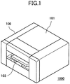
- FIG. 1 illustrates a perspective view for explaining an outer appearance of the image forming apparatus 1000.
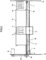
- FIG. 2 illustrates a plan view for explaining a mechanical portion of the image forming apparatus 1000.
- the "image forming apparatus" 1000 being a liquid discharge recording scheme is regarded as an apparatus for forming an image by discharging liquid onto a medium such as paper, string, fabric, cloth, leather, metal, plastic, glass, wood, ceramics, or the like.
- an "image formation” may include not only applying an image having a message such as a letter, a graphic, or the like onto the medium but also applying an image such as a pattern which does not have a message (simply, a droplet is landed onto the medium).
- An “ink” is not limited to material called ink, and may be generically denoted as any liquid used for the image formation such as recording liquid, fixing process liquid, simply called liquid, and the like.
- a DNA specimen, a resist, a pattern material, resin, or the like may be regarded as the ink.
- the "image" is not limited to a planar image and may be an image applied onto a three-dimensionally formed object, an image formed by three-dimensionally modeling a solid object, and the like.
- the image forming apparatus 1000 is regarded as a serial type image forming apparatus.
- a cover 101 is provided to be opened and closed. The mechanical portion inside the image forming apparatus 1000 may be accessed by opening the cover 101.
- a carriage 4 is slidably retained in a main scan direction by a guide member 3 ( FIG. 3 ) bridging laterally between main lateral plates 1A and 1B at right and left sides.
- the carriage 4 is moved in the main scan direction by a timing belt 8 which is stretched between a driving pulley 6 and a driven pulley 7 by a main scan motor 5.
- the carriage 4 includes multiple recording head units 11 each which includes a liquid discharge head regarded as an image forming part for discharging droplets respective to yellow (Y), cyan (C), magenta (M), and black (B), and a head tank for supplying ink to the liquid discharge head.
- a nozzle line having multiple nozzles is arranged in a sub scan direction perpendicular to the main scan direction.
- Each of the recording head units 11 is mounted so that a droplet discharge direction is oriented downward.
- the multiple recording head units 11 are retained by a head holder (not shown) as one unit and mounted to the carriage 4. In the following, the recording head units 11 may be simply called "recording heads 11".
- an encoder scale 15 is arranged along the main scan direction of the carriage 4.
- An encoder sensor 16 is attached at a side of the carriage 4.
- the encoder sensor 16 is formed by a transmissive photosensor for reading a scale (location identification part) of the encoder scale 15.
- a linear encoder is formed as a location detection device by the encoder scale 15 and the encoder sensor 16.
- a conveyance belt 21 is arranged as a conveyance part for conveying a sheet (not shown) in the sub scan direction.
- the conveyance belt 21 is regarded as an endless belt hung on a conveyance roller 22 and tensioning roller 23.
- a sub scan motor 31 By rotating and driving the conveyance roller 22 through a timing belt 32 and a timing pulley 33 by a sub scan motor 31, the conveyance belt 21 is rotated and moved in the sub scan direction.
- a maintenance recovery mechanism 49 is arranged at one side of the main scan direction of the carriage 4 and a lateral side of the conveyance belt 21, to perform a maintenance recovery for the recording heads 11.
- the maintenance recovery mechanism 49 may include a cap member for capping a nozzle surface (a surface on which nozzles are formed) of the recording heads 11, a wiper member for wiping the nozzle surface, an idle discharge receiver for discharging a droplet which does not contribute to the image formation.
- a paper feed and ejection tray 103 is detachably mounted to the body 100.
- the paper feed and ejection tray 103 includes a paper feed part for feeding a sheet to the conveyance belt 21, and a paper ejection part for ejecting the sheet on which the liquid discharged from the recording heads 11 as an image formation part is adhered and an image is formed.
- the sheet fed by the paper feed part is intermittently conveyed by the conveyance belt 21, and the recording heads 11 are driven in response to an image signal by moving the carriage 4 in the main scan direction, thereby one line is recorded by discharging droplets onto the stopped sheet.
- the image is formed onto the sheet by repeating an operation for performing recording of a next line.
- the sheet is ejected.
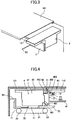
- FIG. 3 is a schematic view for explaining a substantial portion of a carriage part.
- FIG. 4 is a lateral view of the carriage part.
- FIG. 5 is a diagram schematically illustrating a spatial configuration in FIG. 4 .
- a carriage cover 42 is provided to cover an upper portion of a head mounting part 41 at the upper portion of the head mounting part 41 which mounts the recording heads 11. Also, a sensor attaching part 43 is provided.
- the sensor attaching part 43 is regarded as a portion which forms a single member with the carriage cover 42 and which is extended from the head mounting part 41 along a direction for feeding the sheet.
- a head side substrate 112 mounting a head side electrical component is attached to a downward surface of the sensor attaching part 43.
- An encoder sensor 16 is provided on the head side substrate 112.
- the encoder scale 15 is arranged at a location readable for the encoder sensor 16.
- the guide member 3 for slidably guiding the carriage 4 is formed by a steel plate, and includes guide surfaces 301, 302, and 303 to be a supporting surface in order to slidably guide the carriage 4.
- the head mounting part 41 of the carriage 4 includes a sliding part 401 which slidably contacts the guide surface 301 of the guide member 3, a sliding part 402 which slides in contact with the guide surface 302, and a sliding part (slider) 403 which slides in contact with the guide surface 303.
- the guide surface 301 of the guide member 3 is used as a surface to determine a location of the carriage 4 in height.
- the guide surface 302 is used as a surface (rotation stopper) to receive a moment of force due to a weight of the carriage 4 itself.
- the guide surface 303 is used as a surface to determine a location of the carriage 4 in the sub scan direction.
- the guide member 3 is arranged for the entirety of the main scan direction, and is also used as a partition member for separating the head mounting part 41 from the sensor attaching part 43 and the encoder scale 15 in the carriage 4.
- a front stay 61 contacting the guide member 3 is arranged.
- a concave portion 50 is provided to the carriage cover 42 of the carriage 4 between a side of the head mounting part 41 and the sensor attaching part 43.
- a partition member 51 is provided to the cover 101.
- the partition member 51 is fitted in the concave portion 50 of the carriage cover 42, and separates the head mounting part 41 from the sensor attaching part 43 at an upper portion side of the carriage 4.
- the partition member 51 is arranged in the entirety of the main scan direction.
- the head mounting part 41 is separated from the sensor attaching part 43 even at the upper side of the carriage 4. Therefore, by the partition member 51 fitting in the concave portion 50, it is possible to approximately shield the sensor attaching part 43 from the head mounting part 41.
- a pressure plate 71 is arranged with respect to a rear stay 62, and a paper ejection guide 73 under the guide member 3.
- the pressure plate 71 includes, at a tip portion, a pressure roller 72 for pressing the sheet to the conveyance belt 21.
- the paper ejection guide 73 guides the sheet ejected from the conveyance belt 21.
- a space where the carriage 4 moves is divided into a space 501 where the head mounting part 41 of the carriage 4 moves, and a space 502 where the sensor attaching part 43 of the carriage 4 moves and the encoder scale 15 is arranged.
- the carriage 4 includes the head mounting part 41 for mounting the recording heads 11 and at least the sensor attaching part 43 for attaching the encoder sensor 16.
- the sensor attaching part 43 is provided so as to be extended from the head mounting part 41.
- the encoder scale 15 is arranged at the location which the encoder sensor 16 can read.
- the partition member 51 is arranged to separate the head mounting part 41 from the sensor attaching part 43 in the carriage 4. Then, the head mounting part 41 of the carriage 4 is arranged in the space 501, and the sensor attaching part 43 and the encoder scale 15 are arranged in the space 502 different from the space 501 in which the spaces 501 and 502 are separated by the partition member 51. It is possible to reduce the adherence of the mist to the encoder scale 15.
- FIG. 6 is a lateral view of the carriage part in the first embodiment.
- FIG. 7 is a diagram schematically illustrating a spatial configuration in FIG. 6 according to the first embodiment.
- parts that are the same as those illustrated in the previously described figures are given by the same reference numbers.
- the sensor attaching part 43 is provided upward from the head mounting part 41 of the carriage 4.
- the encoder scale 15, which is read by the encoder sensor 16, is arranged above the head mounting part 41.
- the guide member 3 is arranged above the head mounting part 41 and below the encoder sensor 16 of the sensor attaching part 43. Thus, the sensor attaching part 43 is separated from the head mounting part 41.
- the partition member 51 is provided to fit in the concave portion 50 formed on the sensor attaching part 43.
- a space where the carriage 4 is divided into an upper space and a lower space by the guide member 3 and the partition member 51 In a space 501a as the lower space, the head mounting part 41 of the carriage 4 moves. In a space 502a different from the space 501a, the sensor attaching part 43 of the carriage 4 moves and the encoder scale 15 is arranged.
- the mist is shielded by the guide member 3 and the partition member 51. Even if the sensor attaching part 43 moves, the mist hardly enters the space 502a where the encoder scale 15 is arranged. It is possible to reduce adherence of the mist to the encoder scale 15. Moreover, the encoder scale 15 is arranged in the space 502a sectioned above the head mounting part 41. Since the mist does not float upward easily because of gravity, it is possible to acquire a further reduction effect of mist adherence.
- FIG. 8 is a lateral view of the carriage part in the embodiment.
- parts that are the same as those illustrated in the previously described figures are given by the same reference numbers.
- a mist collection member 81 is provided as a partition member.
- the mist collection member 81 may be formed by a brush, a filter, a porous member, a charge member, or the like.
- FIG. 9 is a lateral view of the carriage part in the second embodiment.
- parts that are the same as those illustrated in the previously described figures are given by the same reference numbers.
- the mist collection member 81 is provided as the partition member.
- the mist collection member 81 may be formed by the brush, the filter, the porous member, the charging member, or the like.
- the encoder sensor 16 and the encoder scale 15 may be arranged at an upper surface side of the sensor attaching part 43.
- the encoder sensor 16 and the encoder scale 15 may be arranged at a side of the sensor attaching part 43 which is opposite to the head mounting part 41.
- the first and second embodiments are not limited to the printer configuration, and may be applied to another image forming apparatus such as a multifunction apparatus including a printer, a facsimile, a copier, and the like. Also, the first and second embodiments may be applied to an image forming apparatus using liquid or fixing process liquid other than the ink in the narrow sense, patterning material, or the like.
Landscapes
- Ink Jet (AREA)
- Character Spaces And Line Spaces In Printers (AREA)
Claims (6)
- Appareil de formation d'images, comprenant :un chariot (4) configuré pour monter une tête d'enregistrement (11) pour décharger des gouttelettes et se déplacer dans une direction de balayage principale ;un élément de guidage (3) configuré pour guider de manière coulissante le chariot ;une échelle de codeur (15) disposée le long de la direction de balayage principale ;un capteur de codeur (16) monté sur le chariot et configuré pour lire l'échelle du codeur ; etun élément de séparation (51) ; dans lequel :le chariot inclut une partie de montage de tête (41) configurée pour monter la tête d'enregistrement, et une partie de fixation de capteur (43) sur laquelle le capteur de codeur est monté et s'étendant depuis la partie de montage de tête ;la partie de montage de tête est disposée dans un premier espace, et la partie de fixation de capteur et l'échelle de codeur sont disposées dans un deuxième espace ; caractérisé en ce que :un support (61) s'étend vers le bas et parallèlement à la partie de fixation de capteur (43) et fait face à un bord du chariot dans la direction de sous-balayage ; etl'élément de séparation (51) s'étend horizontalement à partir du support (61) pour entrer en contact avec la partie de fixation de capteur (43) entre le premier espace et le deuxième espace de sorte que le premier espace soit en dessous du deuxième espace et de sorte que l'élément de guidage (3) et l'élément de séparation (51) divisent la partie de montage de tête de la partie de fixation de capteur.
- Appareil de formation d'images selon la revendication 1,
dans lequel au moins une partie de l'élément de séparation (51) chevauche une partie du chariot (4) dans une direction verticale. - Appareil de formation d'images selon la revendication 1,
dans lequel au moins une partie de l'élément de séparation est logée dans une partie concave (50) formée sur la partie de fixation de capteur. - Appareil de formation d'images selon la revendication 1, dans lequel la partie de fixation de capteur s'étend vers le haut à partir de la partie de montage de tête dans le chariot.
- Appareil de formation d'images selon la revendication 1, dans lequel l'élément de séparation est un élément de recueil de brume pour recueillir la brume.
- Appareil de formation d'images selon la revendication 1, dans lequel l'élément de séparation est disposé dans la totalité de la direction de balayage principale.
Applications Claiming Priority (2)
| Application Number | Priority Date | Filing Date | Title |
|---|---|---|---|
| JP2010277462A JP5838548B2 (ja) | 2010-12-13 | 2010-12-13 | 画像形成装置 |
| PCT/JP2011/078629 WO2012081526A1 (fr) | 2010-12-13 | 2011-12-05 | Appareil de formation d'image |
Publications (3)
| Publication Number | Publication Date |
|---|---|
| EP2651648A1 EP2651648A1 (fr) | 2013-10-23 |
| EP2651648A4 EP2651648A4 (fr) | 2015-12-02 |
| EP2651648B1 true EP2651648B1 (fr) | 2020-03-11 |
Family
ID=46244629
Family Applications (1)
| Application Number | Title | Priority Date | Filing Date |
|---|---|---|---|
| EP11849815.3A Active EP2651648B1 (fr) | 2010-12-13 | 2011-12-05 | Appareil de formation d'image |
Country Status (6)
| Country | Link |
|---|---|
| US (5) | US9283785B2 (fr) |
| EP (1) | EP2651648B1 (fr) |
| JP (1) | JP5838548B2 (fr) |
| KR (1) | KR101530017B1 (fr) |
| CN (1) | CN103260886B (fr) |
| WO (1) | WO2012081526A1 (fr) |
Families Citing this family (13)
| Publication number | Priority date | Publication date | Assignee | Title |
|---|---|---|---|---|
| JP3339471B2 (ja) | 1999-08-20 | 2002-10-28 | 村田機械株式会社 | 糸条のサンプリング装置 |
| JP6318616B2 (ja) | 2013-10-02 | 2018-05-09 | 株式会社リコー | 画像形成装置 |
| JP6187290B2 (ja) * | 2014-02-05 | 2017-08-30 | ブラザー工業株式会社 | 印刷装置 |
| CN106917219B (zh) * | 2015-12-28 | 2020-06-02 | 青岛海尔智能技术研发有限公司 | 洗衣机 |
| JP7172252B2 (ja) | 2018-07-27 | 2022-11-16 | 株式会社リコー | 加熱装置 |
| JP7103273B2 (ja) * | 2019-02-28 | 2022-07-20 | カシオ計算機株式会社 | 位置検出装置、印刷装置及び位置検出方法 |
| JP7392458B2 (ja) * | 2019-12-24 | 2023-12-06 | セイコーエプソン株式会社 | 印刷装置 |
| US11633958B2 (en) | 2020-02-05 | 2023-04-25 | Ricoh Company, Ltd. | Liquid discharge apparatus |
| US11400718B2 (en) | 2020-03-12 | 2022-08-02 | Ricoh Company, Ltd. | Liquid discharge apparatus |
| JP7615833B2 (ja) * | 2021-03-30 | 2025-01-17 | セイコーエプソン株式会社 | 複合機、複合機のメンテナンス方法及び複合機の製造方法 |
| US12208628B2 (en) | 2021-10-06 | 2025-01-28 | Ricoh Company, Ltd. | Liquid discharge apparatus |
| EP4223543A3 (fr) | 2022-02-03 | 2023-10-18 | Ricoh Company, Ltd. | Appareil d'évacuation de liquide |
| JP2024049017A (ja) | 2022-09-28 | 2024-04-09 | 株式会社リコー | 液体吐出装置 |
Family Cites Families (30)
| Publication number | Priority date | Publication date | Assignee | Title |
|---|---|---|---|---|
| JP3661959B2 (ja) * | 1996-05-10 | 2005-06-22 | キヤノンファインテック株式会社 | 走査型画像形成装置 |
| US6270187B1 (en) * | 1998-12-14 | 2001-08-07 | Hewlett-Packard Company | Method and apparatus for hiding errors in single-pass incremental printing |
| JP2001113772A (ja) * | 1999-08-11 | 2001-04-24 | Canon Inc | 画像形成装置 |
| JP3595779B2 (ja) * | 2000-07-21 | 2004-12-02 | キヤノン株式会社 | 記録装置 |
| US6524021B2 (en) * | 2000-12-05 | 2003-02-25 | Hewlett-Packard Company | Multiple orientation image forming device and carriage for use with same |
| US6802602B2 (en) | 2001-11-26 | 2004-10-12 | Seiko Epson Corporation | Ink cartridge and ink jet record apparatus using ink cartridge |
| JP4089400B2 (ja) | 2001-11-26 | 2008-05-28 | セイコーエプソン株式会社 | インクカートリッジ |
| JPWO2004011262A1 (ja) * | 2002-07-25 | 2005-11-24 | セイコーエプソン株式会社 | 液体吐出装置、及び、印刷システム |
| JP2004175072A (ja) * | 2002-11-29 | 2004-06-24 | Matsushita Electric Ind Co Ltd | インクジェット記録装置 |
| DE602004000503T2 (de) * | 2003-05-08 | 2006-11-09 | Seiko Epson Corp. | Vorrichtung zur Einstellung des Druckabstandes, Aufzeichnungsgerät und Flüssigkeitsausstossgerät |
| JP4396194B2 (ja) * | 2003-09-09 | 2010-01-13 | セイコーエプソン株式会社 | リニアスケールの位置検出精度維持装置及び該位置検出精度維持装置を備えた記録装置 |
| JP4446158B2 (ja) * | 2004-03-08 | 2010-04-07 | ブラザー工業株式会社 | 画像記録装置 |
| JP4407803B2 (ja) * | 2004-03-08 | 2010-02-03 | ブラザー工業株式会社 | 画像記録装置 |
| JP2005349799A (ja) * | 2004-06-14 | 2005-12-22 | Ricoh Co Ltd | 画像形成装置 |
| US7140793B2 (en) | 2004-06-18 | 2006-11-28 | Lexmark International, Inc. | Imaging apparatus having a carrier support and drive arrangement |
| DE602005015412D1 (de) * | 2004-12-22 | 2009-08-27 | Oce Tech Bv | Drucker mit hin- und herbewegbarem Druckwagen |
| JP4872336B2 (ja) * | 2005-12-19 | 2012-02-08 | ブラザー工業株式会社 | インクジェット記録装置 |
| JP2007176024A (ja) * | 2005-12-28 | 2007-07-12 | Brother Ind Ltd | 画像記録装置 |
| JP4780303B2 (ja) | 2006-01-17 | 2011-09-28 | ブラザー工業株式会社 | 画像記録装置 |
| JP5127580B2 (ja) * | 2007-08-10 | 2013-01-23 | キヤノン株式会社 | 記録装置 |
| JP2009056666A (ja) * | 2007-08-31 | 2009-03-19 | Canon Inc | インクジェット記録装置 |
| JP2009196344A (ja) * | 2008-01-24 | 2009-09-03 | Seiko Epson Corp | 液体吐出装置 |
| JP5088564B2 (ja) * | 2008-02-22 | 2012-12-05 | Nkワークス株式会社 | プリント装置 |
| JP2009214376A (ja) | 2008-03-10 | 2009-09-24 | Ricoh Co Ltd | 画像形成装置及び画像形成方法 |
| JP2010188577A (ja) * | 2009-02-17 | 2010-09-02 | Ricoh Co Ltd | 液滴吐出装置及びこれを備えた画像形成装置 |
| JP4788814B2 (ja) * | 2009-09-30 | 2011-10-05 | ブラザー工業株式会社 | 搬送装置 |
| JP5240225B2 (ja) * | 2010-03-31 | 2013-07-17 | ブラザー工業株式会社 | 記録装置 |
| JP5471791B2 (ja) | 2010-05-07 | 2014-04-16 | 株式会社リコー | 画像形成装置 |
| JP5488186B2 (ja) | 2010-05-11 | 2014-05-14 | 株式会社リコー | 画像形成装置 |
| JP5927812B2 (ja) * | 2011-08-31 | 2016-06-01 | セイコーエプソン株式会社 | 液体噴射装置 |
-
2010
- 2010-12-13 JP JP2010277462A patent/JP5838548B2/ja active Active
-
2011
- 2011-12-05 WO PCT/JP2011/078629 patent/WO2012081526A1/fr not_active Ceased
- 2011-12-05 US US13/990,096 patent/US9283785B2/en active Active
- 2011-12-05 KR KR1020137014352A patent/KR101530017B1/ko active Active
- 2011-12-05 EP EP11849815.3A patent/EP2651648B1/fr active Active
- 2011-12-05 CN CN201180059697.4A patent/CN103260886B/zh not_active Expired - Fee Related
-
2015
- 2015-10-16 US US14/885,474 patent/US20160031239A1/en not_active Abandoned
-
2018
- 2018-09-14 US US16/131,876 patent/US11198310B2/en active Active
-
2021
- 2021-11-08 US US17/520,726 patent/US12030308B2/en active Active
-
2024
- 2024-06-04 US US18/732,886 patent/US20240316961A1/en active Pending
Non-Patent Citations (1)
| Title |
|---|
| None * |
Also Published As
| Publication number | Publication date |
|---|---|
| US11198310B2 (en) | 2021-12-14 |
| US20240316961A1 (en) | 2024-09-26 |
| JP5838548B2 (ja) | 2016-01-06 |
| US20160031239A1 (en) | 2016-02-04 |
| KR20130085427A (ko) | 2013-07-29 |
| CN103260886B (zh) | 2015-06-24 |
| JP2012125955A (ja) | 2012-07-05 |
| EP2651648A4 (fr) | 2015-12-02 |
| CN103260886A (zh) | 2013-08-21 |
| US12030308B2 (en) | 2024-07-09 |
| EP2651648A1 (fr) | 2013-10-23 |
| WO2012081526A1 (fr) | 2012-06-21 |
| KR101530017B1 (ko) | 2015-06-19 |
| US20190009586A1 (en) | 2019-01-10 |
| US20130257986A1 (en) | 2013-10-03 |
| US20220055386A1 (en) | 2022-02-24 |
| US9283785B2 (en) | 2016-03-15 |
Similar Documents
| Publication | Publication Date | Title |
|---|---|---|
| US20240316961A1 (en) | Image forming apparatus | |
| US8714682B2 (en) | Image forming apparatus | |
| EP2386417B1 (fr) | Appareil de formation d'images incluant une tête d'enregistrement à éjection de gouttelettes | |
| US8752953B2 (en) | Image forming apparatus | |
| JP5935338B2 (ja) | 画像形成装置 | |
| JP5663867B2 (ja) | 画像形成装置 | |
| US9108442B2 (en) | Image forming apparatus | |
| US20140152745A1 (en) | Image forming apparatus | |
| CN102248781B (zh) | 图像形成装置 | |
| US8690291B2 (en) | Image forming apparatus | |
| US9409400B2 (en) | Image forming apparatus configured to include nozzle face capping control | |
| US9050838B2 (en) | Image forming apparatus with carriage mounting recording head for ejecting liquid droplets | |
| US8777370B2 (en) | Image forming apparatus | |
| JP2010179503A (ja) | 画像記録装置、及び画像記録装置の制御方法 | |
| US8727494B2 (en) | Droplet ejection device and image forming apparatus | |
| US8672446B2 (en) | Image forming apparatus including recording head for ejecting liquid droplets | |
| CN102673195B (zh) | 图像形成装置 | |
| JP5881026B2 (ja) | 画像形成装置 | |
| JP5835649B2 (ja) | 画像形成装置 | |
| JP2012045726A (ja) | 画像記録装置、及び画像記録装置の制御方法 |
Legal Events
| Date | Code | Title | Description |
|---|---|---|---|
| PUAI | Public reference made under article 153(3) epc to a published international application that has entered the european phase |
Free format text: ORIGINAL CODE: 0009012 |
|
| 17P | Request for examination filed |
Effective date: 20130523 |
|
| AK | Designated contracting states |
Kind code of ref document: A1 Designated state(s): AL AT BE BG CH CY CZ DE DK EE ES FI FR GB GR HR HU IE IS IT LI LT LU LV MC MK MT NL NO PL PT RO RS SE SI SK SM TR |
|
| DAX | Request for extension of the european patent (deleted) | ||
| RA4 | Supplementary search report drawn up and despatched (corrected) |
Effective date: 20151104 |
|
| RIC1 | Information provided on ipc code assigned before grant |
Ipc: B41J 19/18 20060101ALI20151029BHEP Ipc: B41J 2/01 20060101AFI20151029BHEP |
|
| STAA | Information on the status of an ep patent application or granted ep patent |
Free format text: STATUS: EXAMINATION IS IN PROGRESS |
|
| 17Q | First examination report despatched |
Effective date: 20180306 |
|
| REG | Reference to a national code |
Ref country code: DE Ref legal event code: R079 Ref document number: 602011065583 Country of ref document: DE Free format text: PREVIOUS MAIN CLASS: B41J0002010000 Ipc: B41J0019200000 |
|
| GRAP | Despatch of communication of intention to grant a patent |
Free format text: ORIGINAL CODE: EPIDOSNIGR1 |
|
| STAA | Information on the status of an ep patent application or granted ep patent |
Free format text: STATUS: GRANT OF PATENT IS INTENDED |
|
| RIC1 | Information provided on ipc code assigned before grant |
Ipc: B41J 19/20 20060101AFI20191014BHEP |
|
| INTG | Intention to grant announced |
Effective date: 20191028 |
|
| GRAS | Grant fee paid |
Free format text: ORIGINAL CODE: EPIDOSNIGR3 |
|
| GRAA | (expected) grant |
Free format text: ORIGINAL CODE: 0009210 |
|
| STAA | Information on the status of an ep patent application or granted ep patent |
Free format text: STATUS: THE PATENT HAS BEEN GRANTED |
|
| AK | Designated contracting states |
Kind code of ref document: B1 Designated state(s): AL AT BE BG CH CY CZ DE DK EE ES FI FR GB GR HR HU IE IS IT LI LT LU LV MC MK MT NL NO PL PT RO RS SE SI SK SM TR |
|
| REG | Reference to a national code |
Ref country code: GB Ref legal event code: FG4D |
|
| RIN1 | Information on inventor provided before grant (corrected) |
Inventor name: YANASE, NORIKAZU Inventor name: KEMMA, TSUGUYORI Inventor name: KIKURA, MAKOTO |
|
| REG | Reference to a national code |
Ref country code: CH Ref legal event code: EP |
|
| REG | Reference to a national code |
Ref country code: AT Ref legal event code: REF Ref document number: 1242666 Country of ref document: AT Kind code of ref document: T Effective date: 20200315 |
|
| REG | Reference to a national code |
Ref country code: DE Ref legal event code: R096 Ref document number: 602011065583 Country of ref document: DE |
|
| REG | Reference to a national code |
Ref country code: IE Ref legal event code: FG4D |
|
| REG | Reference to a national code |
Ref country code: NL Ref legal event code: FP |
|
| PG25 | Lapsed in a contracting state [announced via postgrant information from national office to epo] |
Ref country code: RS Free format text: LAPSE BECAUSE OF FAILURE TO SUBMIT A TRANSLATION OF THE DESCRIPTION OR TO PAY THE FEE WITHIN THE PRESCRIBED TIME-LIMIT Effective date: 20200311 Ref country code: NO Free format text: LAPSE BECAUSE OF FAILURE TO SUBMIT A TRANSLATION OF THE DESCRIPTION OR TO PAY THE FEE WITHIN THE PRESCRIBED TIME-LIMIT Effective date: 20200611 Ref country code: FI Free format text: LAPSE BECAUSE OF FAILURE TO SUBMIT A TRANSLATION OF THE DESCRIPTION OR TO PAY THE FEE WITHIN THE PRESCRIBED TIME-LIMIT Effective date: 20200311 |
|
| PG25 | Lapsed in a contracting state [announced via postgrant information from national office to epo] |
Ref country code: BG Free format text: LAPSE BECAUSE OF FAILURE TO SUBMIT A TRANSLATION OF THE DESCRIPTION OR TO PAY THE FEE WITHIN THE PRESCRIBED TIME-LIMIT Effective date: 20200611 Ref country code: SE Free format text: LAPSE BECAUSE OF FAILURE TO SUBMIT A TRANSLATION OF THE DESCRIPTION OR TO PAY THE FEE WITHIN THE PRESCRIBED TIME-LIMIT Effective date: 20200311 Ref country code: GR Free format text: LAPSE BECAUSE OF FAILURE TO SUBMIT A TRANSLATION OF THE DESCRIPTION OR TO PAY THE FEE WITHIN THE PRESCRIBED TIME-LIMIT Effective date: 20200612 Ref country code: HR Free format text: LAPSE BECAUSE OF FAILURE TO SUBMIT A TRANSLATION OF THE DESCRIPTION OR TO PAY THE FEE WITHIN THE PRESCRIBED TIME-LIMIT Effective date: 20200311 Ref country code: LV Free format text: LAPSE BECAUSE OF FAILURE TO SUBMIT A TRANSLATION OF THE DESCRIPTION OR TO PAY THE FEE WITHIN THE PRESCRIBED TIME-LIMIT Effective date: 20200311 |
|
| REG | Reference to a national code |
Ref country code: LT Ref legal event code: MG4D |
|
| PG25 | Lapsed in a contracting state [announced via postgrant information from national office to epo] |
Ref country code: IS Free format text: LAPSE BECAUSE OF FAILURE TO SUBMIT A TRANSLATION OF THE DESCRIPTION OR TO PAY THE FEE WITHIN THE PRESCRIBED TIME-LIMIT Effective date: 20200711 Ref country code: SK Free format text: LAPSE BECAUSE OF FAILURE TO SUBMIT A TRANSLATION OF THE DESCRIPTION OR TO PAY THE FEE WITHIN THE PRESCRIBED TIME-LIMIT Effective date: 20200311 Ref country code: PT Free format text: LAPSE BECAUSE OF FAILURE TO SUBMIT A TRANSLATION OF THE DESCRIPTION OR TO PAY THE FEE WITHIN THE PRESCRIBED TIME-LIMIT Effective date: 20200805 Ref country code: CZ Free format text: LAPSE BECAUSE OF FAILURE TO SUBMIT A TRANSLATION OF THE DESCRIPTION OR TO PAY THE FEE WITHIN THE PRESCRIBED TIME-LIMIT Effective date: 20200311 Ref country code: RO Free format text: LAPSE BECAUSE OF FAILURE TO SUBMIT A TRANSLATION OF THE DESCRIPTION OR TO PAY THE FEE WITHIN THE PRESCRIBED TIME-LIMIT Effective date: 20200311 Ref country code: LT Free format text: LAPSE BECAUSE OF FAILURE TO SUBMIT A TRANSLATION OF THE DESCRIPTION OR TO PAY THE FEE WITHIN THE PRESCRIBED TIME-LIMIT Effective date: 20200311 Ref country code: EE Free format text: LAPSE BECAUSE OF FAILURE TO SUBMIT A TRANSLATION OF THE DESCRIPTION OR TO PAY THE FEE WITHIN THE PRESCRIBED TIME-LIMIT Effective date: 20200311 Ref country code: SM Free format text: LAPSE BECAUSE OF FAILURE TO SUBMIT A TRANSLATION OF THE DESCRIPTION OR TO PAY THE FEE WITHIN THE PRESCRIBED TIME-LIMIT Effective date: 20200311 |
|
| REG | Reference to a national code |
Ref country code: AT Ref legal event code: MK05 Ref document number: 1242666 Country of ref document: AT Kind code of ref document: T Effective date: 20200311 |
|
| REG | Reference to a national code |
Ref country code: DE Ref legal event code: R097 Ref document number: 602011065583 Country of ref document: DE |
|
| PLBE | No opposition filed within time limit |
Free format text: ORIGINAL CODE: 0009261 |
|
| STAA | Information on the status of an ep patent application or granted ep patent |
Free format text: STATUS: NO OPPOSITION FILED WITHIN TIME LIMIT |
|
| PG25 | Lapsed in a contracting state [announced via postgrant information from national office to epo] |
Ref country code: DK Free format text: LAPSE BECAUSE OF FAILURE TO SUBMIT A TRANSLATION OF THE DESCRIPTION OR TO PAY THE FEE WITHIN THE PRESCRIBED TIME-LIMIT Effective date: 20200311 Ref country code: IT Free format text: LAPSE BECAUSE OF FAILURE TO SUBMIT A TRANSLATION OF THE DESCRIPTION OR TO PAY THE FEE WITHIN THE PRESCRIBED TIME-LIMIT Effective date: 20200311 Ref country code: ES Free format text: LAPSE BECAUSE OF FAILURE TO SUBMIT A TRANSLATION OF THE DESCRIPTION OR TO PAY THE FEE WITHIN THE PRESCRIBED TIME-LIMIT Effective date: 20200311 Ref country code: AT Free format text: LAPSE BECAUSE OF FAILURE TO SUBMIT A TRANSLATION OF THE DESCRIPTION OR TO PAY THE FEE WITHIN THE PRESCRIBED TIME-LIMIT Effective date: 20200311 |
|
| 26N | No opposition filed |
Effective date: 20201214 |
|
| PG25 | Lapsed in a contracting state [announced via postgrant information from national office to epo] |
Ref country code: SI Free format text: LAPSE BECAUSE OF FAILURE TO SUBMIT A TRANSLATION OF THE DESCRIPTION OR TO PAY THE FEE WITHIN THE PRESCRIBED TIME-LIMIT Effective date: 20200311 Ref country code: PL Free format text: LAPSE BECAUSE OF FAILURE TO SUBMIT A TRANSLATION OF THE DESCRIPTION OR TO PAY THE FEE WITHIN THE PRESCRIBED TIME-LIMIT Effective date: 20200311 |
|
| REG | Reference to a national code |
Ref country code: CH Ref legal event code: PL |
|
| PG25 | Lapsed in a contracting state [announced via postgrant information from national office to epo] |
Ref country code: MC Free format text: LAPSE BECAUSE OF FAILURE TO SUBMIT A TRANSLATION OF THE DESCRIPTION OR TO PAY THE FEE WITHIN THE PRESCRIBED TIME-LIMIT Effective date: 20200311 |
|
| REG | Reference to a national code |
Ref country code: BE Ref legal event code: MM Effective date: 20201231 |
|
| PG25 | Lapsed in a contracting state [announced via postgrant information from national office to epo] |
Ref country code: LU Free format text: LAPSE BECAUSE OF NON-PAYMENT OF DUE FEES Effective date: 20201205 Ref country code: IE Free format text: LAPSE BECAUSE OF NON-PAYMENT OF DUE FEES Effective date: 20201205 |
|
| PG25 | Lapsed in a contracting state [announced via postgrant information from national office to epo] |
Ref country code: CH Free format text: LAPSE BECAUSE OF NON-PAYMENT OF DUE FEES Effective date: 20201231 Ref country code: LI Free format text: LAPSE BECAUSE OF NON-PAYMENT OF DUE FEES Effective date: 20201231 |
|
| PG25 | Lapsed in a contracting state [announced via postgrant information from national office to epo] |
Ref country code: TR Free format text: LAPSE BECAUSE OF FAILURE TO SUBMIT A TRANSLATION OF THE DESCRIPTION OR TO PAY THE FEE WITHIN THE PRESCRIBED TIME-LIMIT Effective date: 20200311 Ref country code: MT Free format text: LAPSE BECAUSE OF FAILURE TO SUBMIT A TRANSLATION OF THE DESCRIPTION OR TO PAY THE FEE WITHIN THE PRESCRIBED TIME-LIMIT Effective date: 20200311 Ref country code: CY Free format text: LAPSE BECAUSE OF FAILURE TO SUBMIT A TRANSLATION OF THE DESCRIPTION OR TO PAY THE FEE WITHIN THE PRESCRIBED TIME-LIMIT Effective date: 20200311 |
|
| PG25 | Lapsed in a contracting state [announced via postgrant information from national office to epo] |
Ref country code: MK Free format text: LAPSE BECAUSE OF FAILURE TO SUBMIT A TRANSLATION OF THE DESCRIPTION OR TO PAY THE FEE WITHIN THE PRESCRIBED TIME-LIMIT Effective date: 20200311 Ref country code: AL Free format text: LAPSE BECAUSE OF FAILURE TO SUBMIT A TRANSLATION OF THE DESCRIPTION OR TO PAY THE FEE WITHIN THE PRESCRIBED TIME-LIMIT Effective date: 20200311 |
|
| PG25 | Lapsed in a contracting state [announced via postgrant information from national office to epo] |
Ref country code: BE Free format text: LAPSE BECAUSE OF NON-PAYMENT OF DUE FEES Effective date: 20201231 |
|
| P01 | Opt-out of the competence of the unified patent court (upc) registered |
Effective date: 20230522 |
|
| PGFP | Annual fee paid to national office [announced via postgrant information from national office to epo] |
Ref country code: DE Payment date: 20251211 Year of fee payment: 15 |
|
| PGFP | Annual fee paid to national office [announced via postgrant information from national office to epo] |
Ref country code: GB Payment date: 20251219 Year of fee payment: 15 |
|
| PGFP | Annual fee paid to national office [announced via postgrant information from national office to epo] |
Ref country code: NL Payment date: 20251219 Year of fee payment: 15 Ref country code: FR Payment date: 20251223 Year of fee payment: 15 |