EP2651732B1 - Procédé permettant d'ajuster la force de serrage exercée par un frein de stationnement - Google Patents
Procédé permettant d'ajuster la force de serrage exercée par un frein de stationnement Download PDFInfo
- Publication number
- EP2651732B1 EP2651732B1 EP11793412.5A EP11793412A EP2651732B1 EP 2651732 B1 EP2651732 B1 EP 2651732B1 EP 11793412 A EP11793412 A EP 11793412A EP 2651732 B1 EP2651732 B1 EP 2651732B1
- Authority
- EP
- European Patent Office
- Prior art keywords
- brake device
- clamping force
- brake
- additional
- actuator
- Prior art date
- Legal status (The legal status is an assumption and is not a legal conclusion. Google has not performed a legal analysis and makes no representation as to the accuracy of the status listed.)
- Active
Links
Images

Classifications
-
- B—PERFORMING OPERATIONS; TRANSPORTING
- B60—VEHICLES IN GENERAL
- B60T—VEHICLE BRAKE CONTROL SYSTEMS OR PARTS THEREOF; BRAKE CONTROL SYSTEMS OR PARTS THEREOF, IN GENERAL; ARRANGEMENT OF BRAKING ELEMENTS ON VEHICLES IN GENERAL; PORTABLE DEVICES FOR PREVENTING UNWANTED MOVEMENT OF VEHICLES; VEHICLE MODIFICATIONS TO FACILITATE COOLING OF BRAKES
- B60T13/00—Transmitting braking action from initiating means to ultimate brake actuator with power assistance or drive; Brake systems incorporating such transmitting means, e.g. air-pressure brake systems
- B60T13/74—Transmitting braking action from initiating means to ultimate brake actuator with power assistance or drive; Brake systems incorporating such transmitting means, e.g. air-pressure brake systems with electrical assistance or drive
-
- B—PERFORMING OPERATIONS; TRANSPORTING
- B60—VEHICLES IN GENERAL
- B60T—VEHICLE BRAKE CONTROL SYSTEMS OR PARTS THEREOF; BRAKE CONTROL SYSTEMS OR PARTS THEREOF, IN GENERAL; ARRANGEMENT OF BRAKING ELEMENTS ON VEHICLES IN GENERAL; PORTABLE DEVICES FOR PREVENTING UNWANTED MOVEMENT OF VEHICLES; VEHICLE MODIFICATIONS TO FACILITATE COOLING OF BRAKES
- B60T8/00—Arrangements for adjusting wheel-braking force to meet varying vehicular or ground-surface conditions, e.g. limiting or varying distribution of braking force
- B60T8/17—Using electrical or electronic regulation means to control braking
-
- B—PERFORMING OPERATIONS; TRANSPORTING
- B60—VEHICLES IN GENERAL
- B60T—VEHICLE BRAKE CONTROL SYSTEMS OR PARTS THEREOF; BRAKE CONTROL SYSTEMS OR PARTS THEREOF, IN GENERAL; ARRANGEMENT OF BRAKING ELEMENTS ON VEHICLES IN GENERAL; PORTABLE DEVICES FOR PREVENTING UNWANTED MOVEMENT OF VEHICLES; VEHICLE MODIFICATIONS TO FACILITATE COOLING OF BRAKES
- B60T7/00—Brake-action initiating means
- B60T7/02—Brake-action initiating means for personal initiation
- B60T7/04—Brake-action initiating means for personal initiation foot actuated
- B60T7/042—Brake-action initiating means for personal initiation foot actuated by electrical means, e.g. using travel or force sensors
-
- B—PERFORMING OPERATIONS; TRANSPORTING
- B60—VEHICLES IN GENERAL
- B60T—VEHICLE BRAKE CONTROL SYSTEMS OR PARTS THEREOF; BRAKE CONTROL SYSTEMS OR PARTS THEREOF, IN GENERAL; ARRANGEMENT OF BRAKING ELEMENTS ON VEHICLES IN GENERAL; PORTABLE DEVICES FOR PREVENTING UNWANTED MOVEMENT OF VEHICLES; VEHICLE MODIFICATIONS TO FACILITATE COOLING OF BRAKES
- B60T13/00—Transmitting braking action from initiating means to ultimate brake actuator with power assistance or drive; Brake systems incorporating such transmitting means, e.g. air-pressure brake systems
- B60T13/10—Transmitting braking action from initiating means to ultimate brake actuator with power assistance or drive; Brake systems incorporating such transmitting means, e.g. air-pressure brake systems with fluid assistance, drive, or release
- B60T13/58—Combined or convertible systems
- B60T13/588—Combined or convertible systems both fluid and mechanical assistance or drive
-
- B—PERFORMING OPERATIONS; TRANSPORTING
- B60—VEHICLES IN GENERAL
- B60T—VEHICLE BRAKE CONTROL SYSTEMS OR PARTS THEREOF; BRAKE CONTROL SYSTEMS OR PARTS THEREOF, IN GENERAL; ARRANGEMENT OF BRAKING ELEMENTS ON VEHICLES IN GENERAL; PORTABLE DEVICES FOR PREVENTING UNWANTED MOVEMENT OF VEHICLES; VEHICLE MODIFICATIONS TO FACILITATE COOLING OF BRAKES
- B60T13/00—Transmitting braking action from initiating means to ultimate brake actuator with power assistance or drive; Brake systems incorporating such transmitting means, e.g. air-pressure brake systems
- B60T13/74—Transmitting braking action from initiating means to ultimate brake actuator with power assistance or drive; Brake systems incorporating such transmitting means, e.g. air-pressure brake systems with electrical assistance or drive
- B60T13/741—Transmitting braking action from initiating means to ultimate brake actuator with power assistance or drive; Brake systems incorporating such transmitting means, e.g. air-pressure brake systems with electrical assistance or drive acting on an ultimate actuator
-
- B—PERFORMING OPERATIONS; TRANSPORTING
- B60—VEHICLES IN GENERAL
- B60T—VEHICLE BRAKE CONTROL SYSTEMS OR PARTS THEREOF; BRAKE CONTROL SYSTEMS OR PARTS THEREOF, IN GENERAL; ARRANGEMENT OF BRAKING ELEMENTS ON VEHICLES IN GENERAL; PORTABLE DEVICES FOR PREVENTING UNWANTED MOVEMENT OF VEHICLES; VEHICLE MODIFICATIONS TO FACILITATE COOLING OF BRAKES
- B60T7/00—Brake-action initiating means
- B60T7/02—Brake-action initiating means for personal initiation
- B60T7/04—Brake-action initiating means for personal initiation foot actuated
- B60T7/045—Brake-action initiating means for personal initiation foot actuated with locking and release means, e.g. providing parking brake application
-
- B—PERFORMING OPERATIONS; TRANSPORTING
- B60—VEHICLES IN GENERAL
- B60T—VEHICLE BRAKE CONTROL SYSTEMS OR PARTS THEREOF; BRAKE CONTROL SYSTEMS OR PARTS THEREOF, IN GENERAL; ARRANGEMENT OF BRAKING ELEMENTS ON VEHICLES IN GENERAL; PORTABLE DEVICES FOR PREVENTING UNWANTED MOVEMENT OF VEHICLES; VEHICLE MODIFICATIONS TO FACILITATE COOLING OF BRAKES
- B60T7/00—Brake-action initiating means
- B60T7/02—Brake-action initiating means for personal initiation
- B60T7/08—Brake-action initiating means for personal initiation hand actuated
- B60T7/10—Disposition of hand control
- B60T7/107—Disposition of hand control with electrical power assistance
-
- F—MECHANICAL ENGINEERING; LIGHTING; HEATING; WEAPONS; BLASTING
- F16—ENGINEERING ELEMENTS AND UNITS; GENERAL MEASURES FOR PRODUCING AND MAINTAINING EFFECTIVE FUNCTIONING OF MACHINES OR INSTALLATIONS; THERMAL INSULATION IN GENERAL
- F16D—COUPLINGS FOR TRANSMITTING ROTATION; CLUTCHES; BRAKES
- F16D65/00—Parts or details
- F16D65/14—Actuating mechanisms for brakes; Means for initiating operation at a predetermined position
- F16D65/16—Actuating mechanisms for brakes; Means for initiating operation at a predetermined position arranged in or on the brake
- F16D65/18—Actuating mechanisms for brakes; Means for initiating operation at a predetermined position arranged in or on the brake adapted for drawing members together, e.g. for disc brakes
Definitions
- the invention relates to a method for adjusting the force exerted by a parking brake clamping force in a vehicle.
- An electromechanical parking brake which has an electric brake motor as an actuator whose rotational movement is converted into an axial adjusting movement of a brake piston.
- the brake piston is a carrier of a brake pad, which is pressed against the end face of a brake disc. About the energization of the brake motor, the height of the clamping force is set.
- electromechanical parking brakes which cooperate with a hydraulic brake device by the brake motor adjusted by the brake piston is additionally acted upon by the pressure of the hydraulic brake device.
- the total clamping force is composed in this case of an electric motor generated share and a hydraulically generated share. In providing the clamping force, noise may be generated due to the pump motor of the hydraulic brake device which generates the required hydraulic pressure.
- the invention has for its object to provide with simple measures and high user comfort, the required clamping force in a parking brake of a vehicle, which includes an electromechanical and a supplementary brake device.
- the inventive method is used in a parking brake in vehicles, which is provided with an electromechanical braking device and with a shiftable braking device.
- the electro-mechanical brake device of the parking brake comprises an electrically actuable actuator, via which an electromechanical clamping force can be generated. To set the vehicle at a standstill, a clamping force is generated via the electromechanical brake device.
- the auxiliary brake device can be switched on, for example, in cases where the electromechanical clamping force is insufficient to fix the vehicle with the required security. It is also possible to connect the additional brake device to relieve the electromechanical brake device, since the electromechanical component of the clamping force when connecting the additional brake device can be reduced accordingly.
- the electric actuator is preferably an electric brake motor, the rotational movement of which is converted into an axial adjusting movement of a brake piston.
- the brake piston is a carrier of a brake lining, which is pressed against the end face of a brake disc.
- an other electrical actuator for generating the electromechanical clamping force for example, an electromagnetic actuator.
- the auxiliary brake device is preferably designed as a hydraulic brake device whose hydraulic pressure is used to generate an additional, supplementary clamping force.
- the brake piston which is adjusted by the electromechanical brake device, be additionally acted upon by the hydraulic pressure, so that the total clamping force composed of an electromechanical and a hydraulic portion.
- a parameter of the electric actuator is adjusted to a defined value, for example, a control of an electrical parameter such as the current in the actuator or a control of the force generated by the actuator.
- the additional clamping force is set to a desired value via an assigned state variable of the auxiliary brake device, specifically without control with feedback loop, but solely on the basis of control without feedback.
- a control for the electromechanical brake device and a control for the auxiliary brake device cooperate. This ensures, on the one hand, a sufficiently accurate adjustment of a total clamping force, which is composed of an electromechanical component and a portion of the auxiliary brake device.
- the regulation of the electromechanical brake device allows precise adjustment of the total clamping force.
- the method can be implemented and carried out in a simple manner due to the uncontrolled control of the auxiliary brake device, since no feedback loop for setting the additional clamping force is required for the auxiliary brake device.
- the noise is reduced, since in the control only a certain, defined setting level of the auxiliary brake device must be achieved, which can be achieved without fluctuating or changing state variables of the auxiliary brake device.
- a constantly changing state variable of the auxiliary brake device must be expected, which is accompanied by a noise that is perceived as unpleasant with changing pitch.
- the auxiliary brake device is a hydraulic brake device, in particular the regular vehicle brake
- the pump motor of the hydraulic brake device for generating the desired hydraulic pressure must be regulated with a continuously changing speed during a control.
- the pump motor is impressed on a specific, defined speed curve, so that permanently changing speeds can be avoided.
- Another advantage is the fact that the risk of vibration tendency by feedback of the motor current of the electric actuator excluded is.
- a tendency to oscillate can be given in parking brakes, in which both the electric brake motor and the hydraulic brake device interacting with the brake motor are subjected to a control.
- the pump speed of the hydraulic pump remains at least almost constant, the component and vehicle electrical system load is reduced.
- the electrical current acting on the actuator current is adjusted on the part of the electromechanical braking device as an electrical characteristic.
- the electric actuator must be subjected to a certain current level.
- the control takes place via the clamping force generated by the actuator.
- the additional clamping force which is generated in the auxiliary brake device, is suitably switched on during the application process of the electromechanical brake device.
- Trigger for the connection can be reaching a defined range of values of a state variable of the actuator.
- the value range for the state variable under consideration can either be predefined or defined as a function of system variables, in particular state variables of the electromechanical brake device and / or the auxiliary brake device.
- the additional assistance can be activated even when falling below a motor speed threshold.
- the additional clamping force assistance can reduce the risk that the brake motor will stop due to an excessive load.
- the additional brake device expediently set to a value that exists as a function or characteristic.
- the desired value of the state variable can be present as a time-dependent or path-dependent profile, so that the state variable can be set correspondingly at the current time or the current, traveled travel of the electromechanical actuator.
- the state variable expediently is the hydraulic pressure, which is adjusted in an unregulated manner to a corresponding nominal value following the curve progression.
- the parameters determining the course of the curve for the state variable of the additional brake device can either be predetermined or determined as a function of other state or characteristic variables, in particular depending on state or characteristic variables of the electric actuator.
- the curve of the setpoint values for the state variable of the auxiliary brake device is designed, for example, as a ramp, which rises up to a defined maximum value. Both the slope of the ramp and the maximum value represent parameters that are either fixed or determined depending on other parameters of the parking brake during operation.
- the brake motor as the electric actuator of the electromechanical brake device can not provide the required clamping force due to a power loss
- the power loss can be compensated for by adapting the setpoint curve for the additional brake device, in particular by raising the gradient in the ramp-shaped rise and / or by raising the maximum value , Even with a defect in the auxiliary brake device, for example in the embodiment as a hydraulic brake device in air in the hydraulic system, by adjusting the parameters of the desired characteristic at least a partial compensation of the power loss can be achieved.
- the inventive method runs in a control or control unit in the vehicle, which may be part of the parking brake system.
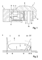
- Fig. 1 is an electromechanical parking brake 1 shown for setting a vehicle at a standstill.
- the parking brake 1 comprises a caliper 2 with a pair of pliers 9, which engages over a brake disk 10.
- the parking brake 1 an electric motor as a brake motor 3, which drives a spindle 4 in rotation, on which a spindle member 5 is rotatably mounted.
- the spindle member 5 Upon rotation of the spindle 4, the spindle member 5 is moved axially.
- the spindle component 5 moves within a brake piston 6, which is the carrier of a brake pad 7, which is pressed by the brake piston 6 against the brake disk 10.
- On the opposite side of the brake disk 10 is another brake pad 8, which is held stationary on the pliers 9.
- the spindle member 5 during a rotational movement of the spindle 4 axially forward in the direction of the brake disc 10 to move or at an opposite rotational movement of the spindle 4 axially to the rear until reaching a stop 11.
- the spindle component 5 acts on the inner end face of the brake piston 6, whereby the axially displaceably mounted in the parking brake 1 brake piston 6 is pressed with the brake pad 7 against the facing end face of the brake disc 10.
- the parking brake can be assisted by a hydraulic vehicle brake, so that the clamping force is composed of an electromotive component and a hydraulic component.
- the rear side of the brake piston 6 facing the brake motor is subjected to pressurized hydraulic fluid.
- Phase II between times t2 and t3 marks the idling phase in which an idling current, an open circuit voltage and an idling speed are established.
- the clamping force of the wheel brake is still zero in this phase because the nut is not yet in contact with the piston crown.
- the pressure p in the hydraulic brake device is still equal to zero.
- Phase III between the times t3 and t4, the force is built up.
- the nut is in contact with the piston crown and the piston is pressed against the brake rotor by the rotation of the spindle.
- the current I of the brake motor increases at.
- the voltage U of the brake motor drops slightly in this phase due to the load of the brake motor from the level of the open circuit voltage.
- the speed n of the brake motor also drops with increasing clamping force build-up.
- the hydraulic pump of the hydraulic brake device is switched on and built up a hydraulic pressure p.
- the target clamping force can z. B. have a value that is close to the maximum clamping force of the brake motor.
- Phase IV between times t4 and t5 begins when the target clamping force is reached.
- both brake systems are active and the electric brake device is supported by the hydraulic brake device.
- the total clamping force F is composed of a proportion of the electric brake motor and a portion of the hydraulic brake device.
- the current I of the brake motor is limited in phase IV to a maximum current.
- the hydraulic pressure p increases until a predetermined total clamping force is reached. Thereafter, the brake motor and the pump motor of the hydraulic brake device are turned off. As a result, the hydraulic pressure p, the current I, the voltage U and the rotational speed n of the brake motor fall to zero.
- the total clamping force F is held.
- the hydraulic brake device is activated only in phase IV, so that at the time t4 with the construction of the hydraulic pressure p is started, which has reached its maximum at the end of phase IV, ie at time t5.
- the timing of the pressure assist by the hydraulic brake device is not necessarily coupled to the time t4 at which the phase IV begins.
- the time of the hydraulic assistance as a function of a characteristic of the electric brake motor, in particular the current of the brake motor is set. For this purpose, it is checked whether the current I of the brake motor exceeds an associated threshold value I lim . If this is the case, the hydraulic pressure assistance is started.
- the current threshold I lim as a function of the voltage U.
- the threshold value I lim thus does not represent a constant quantity, but is adapted adaptively as a function of the motor voltage U.
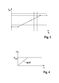
- the functional course according to Fig. 3 is designed as a ramp that reaches a maximum to a certain voltage value.
- phase IV tripping may be adjusted to the operating conditions of the brake motor.
- the adaptive adjustment of the threshold value is required because the maximum possible motor current decreases in proportion to the motor voltage and thus also the maximum possible engine torque in the parking brake is available only to a reduced extent.
- Fig. 4 the pressure curve of the hydraulic pressure p is shown as a function of time.
- the pressure curve is specified as a setpoint curve for setting the hydraulic brake device.
- the adjustment is made in a purely controlled manner without feedback loop; only one characteristic of the electric brake motor is adjusted to a desired value.
- the brake motor is controlled in phase III via the current.
- phase IV on the other hand, the force generated by the brake motor is adjusted by the distance covered and the stiffness of the caliper.
- the setpoint curve of the pressure p is designed as a ramp with a slope dp / dt, which reaches its maximum value at p max .
- the slope dp / dt and the maximum value p max represent parameters which are either fixed or determined as a function of state or characteristic variables of the electromechanical brake device and / or the hydraulic brake device. For example, a higher gradient and a higher maximum value in the course of the setpoint curve p can be selected if a power loss occurs in the electromechanical braking device.
- Fig. 5 is a flowchart with individual process steps for adjusting the total clamping force in the parking brake shown.
- the flowchart starts according to the first method step 20 in the force increase phase 3 at the time t3.
- a clamping force is specified as the target clamping force, with which the vehicle can be fixed on an inclined surface with 30% inclination.
- the further method steps 22 and 23 correspond to the force increase phase III.
- the trigger criterion for starting the hydraulic Clamping force assistance determined.
- the current threshold I lim according to the in Fig. 3 determined relationship determined.
- step 23 it is queried whether the current motor current I exceeds the current threshold value I lim . If this is not the case, the no-branch ("N") is returned following and checked again at regular intervals whether the motor current I exceeds the associated threshold value I lim .
- the Yes branch (“Y") is proceeded to the next method step 24, which, like the subsequent phase IV process step 25 (FIG. Fig. 2 ) assigned.
- a controlled pressure ramp according to the diagram is detected Fig. 4 started, in this case, the hydraulic pressure in the hydraulic brake device according to the predetermined ramp function after Fig. 4 booted.
- the next step 25 it is queried whether the total clamping force, which is composed of the electromotive and the hydraulic portion, has been achieved. If this is not the case, the no-branch is returned to the query and the query is started again at regular intervals. If, on the other hand, the total clamping force is reached, the yes branch is continued following the next method step 26, which marks the end of the application process in the parking brake. In step 26, the time t5 ( Fig. 2 ) reached.
Landscapes
- Engineering & Computer Science (AREA)
- Mechanical Engineering (AREA)
- Transportation (AREA)
- General Engineering & Computer Science (AREA)
- Braking Systems And Boosters (AREA)
- Regulating Braking Force (AREA)
- Braking Arrangements (AREA)
Claims (14)
- Procédé permettant d'ajuster la force de serrage exercée par un frein de stationnement (1), avec un dispositif de freinage électromécanique comprenant un actionneur électrique (3) pour générer une force de serrage électromécanique et avec un dispositif de freinage supplémentaire pouvant être activé en complément pour générer une force de serrage supplémentaire, caractérisé en ce qu'une grandeur caractéristique de l'actionneur électrique est réglée à une valeur définie et en ce qu'en même temps une grandeur d'état du dispositif de freinage supplémentaire déterminant la force de serrage supplémentaire est ajustée à une valeur de consigne sans régulation à rétroaction.
- Procédé selon la revendication 1, caractérisé en ce que le courant alimentant l'actionneur (3) est réglé en tant que grandeur caractéristique.
- Procédé selon la revendication 1 ou 2, caractérisé en ce que la force de serrage générée par l'actionneur (3) est réglée en tant que grandeur caractéristique.
- Procédé selon l'une quelconque des revendications 1 à 3, caractérisé en ce que la force de serrage supplémentaire du dispositif de freinage supplémentaire est activée lorsqu'une grandeur d'état de l'actionneur (3) se situe en dehors d'une plage de valeurs définie.
- Procédé selon la revendication 4, caractérisé en ce que la force de serrage supplémentaire du dispositif de freinage supplémentaire est activée lorsque la grandeur caractéristique à réguler de l'actionneur (3) ou une grandeur corrélée à celle-ci dépasse une valeur seuil.
- Procédé selon l'une quelconque des revendications 1 à 5, caractérisé en ce que la grandeur d'état du dispositif de freinage supplémentaire existe en tant que courbe dépendante du temps et une valeur de la grandeur d'état correspondant à l'instant actuel est ajustée.
- Procédé selon la revendication 6, caractérisé en ce que les paramètres déterminant la courbe sont prédéfinis de manière fixée.
- Procédé selon la revendication 6, caractérisé en ce que les paramètres déterminant la courbe sont déterminés en tant que fonction de paramètres ou de grandeurs d'état de l'actionneur électrique (3).
- Procédé selon la revendication 8, caractérisé en ce qu'en cas de dégradation de fonction ou d'un défaut de l'actionneur électrique (3) et/ou du dispositif de freinage supplémentaire, les paramètres déterminant la courbe sont adaptés.
- Procédé selon l'une quelconque des revendications 1 à 9, caractérisé en ce que la grandeur d'état du dispositif de freinage supplémentaire présente une augmentation en forme de rampe jusqu'à l'atteinte d'une valeur maximale.
- Procédé selon l'une quelconque des revendications 1 à 10, caractérisé en ce que le dispositif de freinage supplémentaire est un frein hydraulique de véhicule et la grandeur d'état est la pression hydraulique.
- Procédé selon l'une quelconque des revendications 1 à 11, caractérisé en ce que l'actionneur électrique (3) du dispositif de freinage électromécanique est réalisé sous forme de moteur de frein électrique (3) dont le régime (n) est régulé par le biais du courant (I).
- Appareil de régulation ou de commande pour mettre en oeuvre le procédé selon l'une quelconque des revendications 1 à 12, caractérisé en ce que des moyens de réglage d'une grandeur caractéristique de l'actionneur électrique à une valeur définie ainsi que des moyens d'ajustement d'une grandeur d'état déterminant la force de serrage supplémentaire du dispositif de freinage supplémentaire à une valeur de consigne sans régulation à rétroaction sont prévus, le réglage de la grandeur caractéristique et l'ajustement de la grandeur d'état s'effectuant en même temps.
- Frein de stationnement dans un véhicule comprenant un appareil de régulation ou de commande selon la revendication 13.
Applications Claiming Priority (2)
| Application Number | Priority Date | Filing Date | Title |
|---|---|---|---|
| DE102010063345A DE102010063345A1 (de) | 2010-12-17 | 2010-12-17 | Verfahren zum Einstellen der von einer Feststellbremse ausgeübten Klemmkraft |
| PCT/EP2011/071772 WO2012080024A1 (fr) | 2010-12-17 | 2011-12-05 | Procédé permettant d'ajuster la force de serrage exercée par un frein de stationnement |
Publications (2)
| Publication Number | Publication Date |
|---|---|
| EP2651732A1 EP2651732A1 (fr) | 2013-10-23 |
| EP2651732B1 true EP2651732B1 (fr) | 2015-02-25 |
Family
ID=45217544
Family Applications (1)
| Application Number | Title | Priority Date | Filing Date |
|---|---|---|---|
| EP11793412.5A Active EP2651732B1 (fr) | 2010-12-17 | 2011-12-05 | Procédé permettant d'ajuster la force de serrage exercée par un frein de stationnement |
Country Status (7)
| Country | Link |
|---|---|
| US (1) | US9031756B2 (fr) |
| EP (1) | EP2651732B1 (fr) |
| JP (1) | JP5723459B2 (fr) |
| KR (1) | KR101941302B1 (fr) |
| CN (1) | CN103249621B (fr) |
| DE (1) | DE102010063345A1 (fr) |
| WO (1) | WO2012080024A1 (fr) |
Families Citing this family (23)
| Publication number | Priority date | Publication date | Assignee | Title |
|---|---|---|---|---|
| DE102009047127B4 (de) * | 2009-11-25 | 2023-07-27 | Robert Bosch Gmbh | Verfahren zum Betreiben einer Feststellbremse eines Fahrzeugs |
| DE102010040563A1 (de) * | 2010-09-10 | 2012-03-15 | Robert Bosch Gmbh | Verfahren zum Einstellen der von einer Feststellbremse ausgeübten Klemmkraft |
| DE102011101062A1 (de) * | 2011-05-10 | 2012-11-15 | Lucas Automotive Gmbh | Technik zum Ermitteln einer an einer hydraulisch und mechanisch betätigbaren Fahrzeugbremse anliegenden Betätigungskraft |
| DE102013106128A1 (de) * | 2012-07-16 | 2014-06-12 | Claas Selbstfahrende Erntemaschinen Gmbh | Landwirtschaftliche Arbeitsmaschine mit zumindest einer Steuerungseinrichtung |
| DE102012223178B4 (de) * | 2012-12-14 | 2025-01-23 | Robert Bosch Gmbh | Verfahren zum Betätigen einer Feststellbremse mit einem elektromotorisch angetriebenen Feststellbrems-Mechanismus |
| DE102014202152B4 (de) * | 2014-02-06 | 2026-02-05 | Robert Bosch Gmbh | Verfahren zum Bestimmen einer Auslösebedingung für eine Rekalibrierung einer automatischen Parkbremse |
| FR3031488B1 (fr) * | 2015-01-13 | 2017-02-17 | Faiveley Transp Amiens | Systeme de freinage ferroviaire pour vehicule ferroviaire et procede de freinage d'un vehicule ferroviaire comportant un tel systeme |
| DE102015206034A1 (de) * | 2015-04-02 | 2016-10-06 | Robert Bosch Gmbh | Verfahren und Vorrichtung zum Betreiben eines Bremssystems eines Fahrzeugs, Bremssystem |
| DE102015217118B3 (de) * | 2015-09-08 | 2016-08-18 | Robert Bosch Gmbh | Fahrerassistenzsystem mit reduzierter Aktivierungszeit |
| US10137878B2 (en) | 2015-10-14 | 2018-11-27 | Akebono Brake Industry Co., Ltd. | Method for controlling a parking brake system |
| US10427665B2 (en) | 2016-03-21 | 2019-10-01 | Simmonds Precision Products, Inc. | Force feedback fault detection and accommodation for a multi-channel electric brake actuator controller |
| DE102016205298A1 (de) * | 2016-03-31 | 2017-10-05 | Robert Bosch Gmbh | Verfahren zum Bereitstellen einer Bremskraft in einem Fahrzeug |
| DE102016213645A1 (de) * | 2016-07-26 | 2018-02-01 | Robert Bosch Gmbh | Verfahren zum Betreiben einer automatisierten Feststellbremse |
| DE102016219241A1 (de) * | 2016-10-05 | 2018-04-05 | Robert Bosch Gmbh | Verfahren zum Betreiben einer automatisierten Feststellbremse |
| DE102016223808A1 (de) * | 2016-11-30 | 2018-05-30 | Robert Bosch Gmbh | Verfahren und Vorrichtung zum Betreiben eines hydraulischen Bremssystems, Bremssystem |
| JP6846077B2 (ja) * | 2017-01-20 | 2021-03-24 | 日立Astemo株式会社 | ブレーキシステム |
| CN107237848B (zh) * | 2017-07-03 | 2019-01-25 | 同济大学 | 基于智能型驱动器的制动器制动力矩调控方法 |
| JP7056301B2 (ja) * | 2018-03-26 | 2022-04-19 | 株式会社アドヴィックス | 制動制御装置 |
| CN112955357B (zh) * | 2018-09-03 | 2023-11-03 | 乐姆宝公开有限公司 | 用于检测机动车辆的电致动的制动装置的失灵的方法 |
| JP7392669B2 (ja) * | 2021-01-27 | 2023-12-06 | トヨタ自動車株式会社 | ブレーキシステム |
| US12330608B2 (en) | 2022-10-14 | 2025-06-17 | Akebono Brake Industry Co., Ltd. | Method for controlling an electromechanical brake system |
| FR3144794A1 (fr) * | 2023-01-06 | 2024-07-12 | Hitachi Astemo France | Frein a freinage hydraulique ou electromecanique et hydraulique suivant une intensite de freinage |
| US12594924B2 (en) * | 2024-05-02 | 2026-04-07 | GM Global Technology Operations LLC | Vehicle brake-by-wire diagnostic system and method |
Family Cites Families (15)
| Publication number | Priority date | Publication date | Assignee | Title |
|---|---|---|---|---|
| US6311808B1 (en) * | 1996-02-09 | 2001-11-06 | Continental Teves Ag & Co., Ohg | Combined service and parking brake system |
| JP4058068B2 (ja) * | 1999-09-21 | 2008-03-05 | トヨタ自動車株式会社 | ブレーキ制御装置 |
| JP4033281B2 (ja) | 2000-09-06 | 2008-01-16 | 日産自動車株式会社 | 制動装置 |
| ATE312301T1 (de) * | 2002-04-26 | 2005-12-15 | Estop Gmbh | Kraftfahrzeugbremsanlage mit parkbremsfunktion und elektromechanische radbremse für eine solche kraftfahrzeugbremsanlage |
| DE10302357B3 (de) * | 2003-01-22 | 2004-07-08 | Lucas Automotive Gmbh | Fahrzeugbremsanlage mit Feststellbremseinrichtung |
| DE10361042B3 (de) * | 2003-12-23 | 2005-05-25 | Lucas Automotive Gmbh | Feststellbremse und Verfahren zur Steuerung derselben |
| DE102004004992B4 (de) * | 2004-01-30 | 2008-03-13 | Lucas Automotive Gmbh | Verfahren zum Betreiben der Bremsausrüstung eines Fahrzeugs |
| DE102006037660A1 (de) * | 2005-11-04 | 2007-07-19 | Continental Teves Ag & Co. Ohg | Hydraulische Fahrzeugbremse mit integrierter elektromotorisch betätigbarer Feststellbremse |
| US8408660B2 (en) * | 2006-08-31 | 2013-04-02 | Hitachi, Ltd. | Disc brake apparatus |
| KR101644779B1 (ko) * | 2006-09-27 | 2016-08-02 | 콘티넨탈 테베스 아게 운트 코. 오하게 | 전기기계 구동식 주차 브레이크를 갖는 결합식 차량 브레이크와 회전 운동을 병진 운동으로 전환시키는 기어 |
| DE102008018749A1 (de) * | 2007-09-12 | 2009-03-26 | Continental Teves Ag & Co. Ohg | Verfahren zum gesicherten Lösen einer elektromechanisch betätigbaren Feststellbremse |
| EP2214944B1 (fr) * | 2007-10-24 | 2011-08-31 | Continental Teves AG & Co. oHG | Frein de stationnement et procédé de fonctionnement |
| JP2009126501A (ja) * | 2007-11-28 | 2009-06-11 | Advics Co Ltd | 駐車ブレーキ装置 |
| JP2010241389A (ja) * | 2009-04-10 | 2010-10-28 | Toyota Motor Corp | 電動ブレーキ装置 |
| DE102009047127B4 (de) * | 2009-11-25 | 2023-07-27 | Robert Bosch Gmbh | Verfahren zum Betreiben einer Feststellbremse eines Fahrzeugs |
-
2010
- 2010-12-17 DE DE102010063345A patent/DE102010063345A1/de not_active Withdrawn
-
2011
- 2011-12-05 CN CN201180060841.6A patent/CN103249621B/zh not_active Expired - Fee Related
- 2011-12-05 KR KR1020137015492A patent/KR101941302B1/ko not_active Expired - Fee Related
- 2011-12-05 JP JP2013543640A patent/JP5723459B2/ja not_active Expired - Fee Related
- 2011-12-05 EP EP11793412.5A patent/EP2651732B1/fr active Active
- 2011-12-05 WO PCT/EP2011/071772 patent/WO2012080024A1/fr not_active Ceased
- 2011-12-05 US US13/994,878 patent/US9031756B2/en active Active
Also Published As
| Publication number | Publication date |
|---|---|
| DE102010063345A1 (de) | 2012-06-21 |
| US9031756B2 (en) | 2015-05-12 |
| KR20130129982A (ko) | 2013-11-29 |
| CN103249621A (zh) | 2013-08-14 |
| EP2651732A1 (fr) | 2013-10-23 |
| US20130338896A1 (en) | 2013-12-19 |
| WO2012080024A1 (fr) | 2012-06-21 |
| JP5723459B2 (ja) | 2015-05-27 |
| JP2014504231A (ja) | 2014-02-20 |
| CN103249621B (zh) | 2016-05-04 |
| KR101941302B1 (ko) | 2019-01-22 |
Similar Documents
| Publication | Publication Date | Title |
|---|---|---|
| EP2651732B1 (fr) | Procédé permettant d'ajuster la force de serrage exercée par un frein de stationnement | |
| EP2464551B1 (fr) | Procédé pour régler la force de serrage d'un frein de stationnement commande par un moteur electrique à assistance hydraulique | |
| EP2819896B1 (fr) | Procédé de mise à disposition d'une force de serrage exercée par un frein de stationnement | |
| DE102014203350B4 (de) | Verfahren zum Einstellen einer Feststellbremse in einem Fahrzeug | |
| EP3204660B1 (fr) | Dispositif de freinage pour un véhicule automobile et procédé de commande du dispositif de freinage avec superposition de différentes composantes de force | |
| DE102010002825A1 (de) | Verfahren zum Einstellen der von einer Feststellbremse ausgeübten Klemmkraft | |
| DE102011004786A1 (de) | Verfahren zum Einstellen der von einer Feststellbremse ausgeübten Klemmkraft in einem Fahrzeug | |
| EP2651733B1 (fr) | Procédé permettant d'ajuster la force de serrage exercée par un frein de stationnement | |
| EP2651720B1 (fr) | Procédé de réglage de la force de serrage exercée par un frein de stationnement | |
| WO2011064032A1 (fr) | Procédé destiné au fonctionnement d'un frein de stationnement d'un véhicule | |
| DE102011004772A1 (de) | Verfahren zum Einstellen der von einer Feststellbremse ausgeübten Klemmkraft | |
| DE102015210431A1 (de) | Verfahren zum Ansteuern einer Feststellbremse in einem Fahrzeug | |
| WO2012130494A1 (fr) | Procédé de réglage d'un frein de stationnement dans un véhicule | |
| DE102015211461A1 (de) | Verfahren zum Überprüfen der Bremskraft in einem Fahrzeug | |
| DE102011005843B4 (de) | Verfahren zum Abbau der von einer Feststellbermse ausgeübten Klemmkraft | |
| WO2017198372A1 (fr) | Procédé pour vérifier la force de freinage dans un véhicule | |
| DE102012205030A1 (de) | Vorrichtung und Verfahren zum Ansteuern einer Feststellbremse eines Kraftfahrzeugs | |
| DE102016214195A1 (de) | Verfahren zur Funktionsprüfung einer elektromechanischen Bremsvorrichtung | |
| EP3468848A1 (fr) | Procédé pour actionner un dispositif de freinage électromécanique | |
| WO2012079803A2 (fr) | Procédé de réglage de la force de serrage exercée par un frein de stationnement | |
| DE102012205340B4 (de) | Verfahren und Vorrichtung zur Regelung eines elektrohydraulischen Bremssystems | |
| DE102014211380B4 (de) | Verfahren zum Betrieb eines elektromechanischen Fahrzeugbremssystems | |
| DE102016214593A1 (de) | Verfahren zum Erzeugen einer Bremskraft in einem Fahrzeug | |
| WO2017167482A1 (fr) | Procédé pour fournir une force de freinage dans un véhicule | |
| DE102011005864A1 (de) | Verfahren zum Einstellen einer Feststellbremse in einem Fahrzeug |
Legal Events
| Date | Code | Title | Description |
|---|---|---|---|
| PUAI | Public reference made under article 153(3) epc to a published international application that has entered the european phase |
Free format text: ORIGINAL CODE: 0009012 |
|
| 17P | Request for examination filed |
Effective date: 20130717 |
|
| AK | Designated contracting states |
Kind code of ref document: A1 Designated state(s): AL AT BE BG CH CY CZ DE DK EE ES FI FR GB GR HR HU IE IS IT LI LT LU LV MC MK MT NL NO PL PT RO RS SE SI SK SM TR |
|
| DAX | Request for extension of the european patent (deleted) | ||
| GRAP | Despatch of communication of intention to grant a patent |
Free format text: ORIGINAL CODE: EPIDOSNIGR1 |
|
| INTG | Intention to grant announced |
Effective date: 20141029 |
|
| RIN1 | Information on inventor provided before grant (corrected) |
Inventor name: PUTZER, TOBIAS Inventor name: BAEHRLE-MILLER, FRANK Inventor name: SCHANZENBACH, MATTHIAS Inventor name: MUELLER, ULRIKE |
|
| GRAS | Grant fee paid |
Free format text: ORIGINAL CODE: EPIDOSNIGR3 |
|
| GRAA | (expected) grant |
Free format text: ORIGINAL CODE: 0009210 |
|
| AK | Designated contracting states |
Kind code of ref document: B1 Designated state(s): AL AT BE BG CH CY CZ DE DK EE ES FI FR GB GR HR HU IE IS IT LI LT LU LV MC MK MT NL NO PL PT RO RS SE SI SK SM TR |
|
| REG | Reference to a national code |
Ref country code: GB Ref legal event code: FG4D Free format text: NOT ENGLISH |
|
| REG | Reference to a national code |
Ref country code: CH Ref legal event code: EP |
|
| REG | Reference to a national code |
Ref country code: IE Ref legal event code: FG4D Free format text: LANGUAGE OF EP DOCUMENT: GERMAN |
|
| REG | Reference to a national code |
Ref country code: DE Ref legal event code: R096 Ref document number: 502011006038 Country of ref document: DE Effective date: 20150409 |
|
| REG | Reference to a national code |
Ref country code: AT Ref legal event code: REF Ref document number: 711673 Country of ref document: AT Kind code of ref document: T Effective date: 20150415 |
|
| REG | Reference to a national code |
Ref country code: NL Ref legal event code: VDEP Effective date: 20150225 |
|
| REG | Reference to a national code |
Ref country code: LT Ref legal event code: MG4D |
|
| PG25 | Lapsed in a contracting state [announced via postgrant information from national office to epo] |
Ref country code: FI Free format text: LAPSE BECAUSE OF FAILURE TO SUBMIT A TRANSLATION OF THE DESCRIPTION OR TO PAY THE FEE WITHIN THE PRESCRIBED TIME-LIMIT Effective date: 20150225 Ref country code: LT Free format text: LAPSE BECAUSE OF FAILURE TO SUBMIT A TRANSLATION OF THE DESCRIPTION OR TO PAY THE FEE WITHIN THE PRESCRIBED TIME-LIMIT Effective date: 20150225 Ref country code: ES Free format text: LAPSE BECAUSE OF FAILURE TO SUBMIT A TRANSLATION OF THE DESCRIPTION OR TO PAY THE FEE WITHIN THE PRESCRIBED TIME-LIMIT Effective date: 20150225 Ref country code: NO Free format text: LAPSE BECAUSE OF FAILURE TO SUBMIT A TRANSLATION OF THE DESCRIPTION OR TO PAY THE FEE WITHIN THE PRESCRIBED TIME-LIMIT Effective date: 20150525 Ref country code: SE Free format text: LAPSE BECAUSE OF FAILURE TO SUBMIT A TRANSLATION OF THE DESCRIPTION OR TO PAY THE FEE WITHIN THE PRESCRIBED TIME-LIMIT Effective date: 20150225 Ref country code: HR Free format text: LAPSE BECAUSE OF FAILURE TO SUBMIT A TRANSLATION OF THE DESCRIPTION OR TO PAY THE FEE WITHIN THE PRESCRIBED TIME-LIMIT Effective date: 20150225 |
|
| PG25 | Lapsed in a contracting state [announced via postgrant information from national office to epo] |
Ref country code: LV Free format text: LAPSE BECAUSE OF FAILURE TO SUBMIT A TRANSLATION OF THE DESCRIPTION OR TO PAY THE FEE WITHIN THE PRESCRIBED TIME-LIMIT Effective date: 20150225 Ref country code: IS Free format text: LAPSE BECAUSE OF FAILURE TO SUBMIT A TRANSLATION OF THE DESCRIPTION OR TO PAY THE FEE WITHIN THE PRESCRIBED TIME-LIMIT Effective date: 20150625 Ref country code: RS Free format text: LAPSE BECAUSE OF FAILURE TO SUBMIT A TRANSLATION OF THE DESCRIPTION OR TO PAY THE FEE WITHIN THE PRESCRIBED TIME-LIMIT Effective date: 20150225 Ref country code: GR Free format text: LAPSE BECAUSE OF FAILURE TO SUBMIT A TRANSLATION OF THE DESCRIPTION OR TO PAY THE FEE WITHIN THE PRESCRIBED TIME-LIMIT Effective date: 20150526 |
|
| PG25 | Lapsed in a contracting state [announced via postgrant information from national office to epo] |
Ref country code: NL Free format text: LAPSE BECAUSE OF FAILURE TO SUBMIT A TRANSLATION OF THE DESCRIPTION OR TO PAY THE FEE WITHIN THE PRESCRIBED TIME-LIMIT Effective date: 20150225 |
|
| PG25 | Lapsed in a contracting state [announced via postgrant information from national office to epo] |
Ref country code: SK Free format text: LAPSE BECAUSE OF FAILURE TO SUBMIT A TRANSLATION OF THE DESCRIPTION OR TO PAY THE FEE WITHIN THE PRESCRIBED TIME-LIMIT Effective date: 20150225 Ref country code: DK Free format text: LAPSE BECAUSE OF FAILURE TO SUBMIT A TRANSLATION OF THE DESCRIPTION OR TO PAY THE FEE WITHIN THE PRESCRIBED TIME-LIMIT Effective date: 20150225 Ref country code: EE Free format text: LAPSE BECAUSE OF FAILURE TO SUBMIT A TRANSLATION OF THE DESCRIPTION OR TO PAY THE FEE WITHIN THE PRESCRIBED TIME-LIMIT Effective date: 20150225 Ref country code: RO Free format text: LAPSE BECAUSE OF FAILURE TO SUBMIT A TRANSLATION OF THE DESCRIPTION OR TO PAY THE FEE WITHIN THE PRESCRIBED TIME-LIMIT Effective date: 20150225 Ref country code: CZ Free format text: LAPSE BECAUSE OF FAILURE TO SUBMIT A TRANSLATION OF THE DESCRIPTION OR TO PAY THE FEE WITHIN THE PRESCRIBED TIME-LIMIT Effective date: 20150225 |
|
| REG | Reference to a national code |
Ref country code: DE Ref legal event code: R097 Ref document number: 502011006038 Country of ref document: DE |
|
| PG25 | Lapsed in a contracting state [announced via postgrant information from national office to epo] |
Ref country code: PL Free format text: LAPSE BECAUSE OF FAILURE TO SUBMIT A TRANSLATION OF THE DESCRIPTION OR TO PAY THE FEE WITHIN THE PRESCRIBED TIME-LIMIT Effective date: 20150225 |
|
| REG | Reference to a national code |
Ref country code: FR Ref legal event code: PLFP Year of fee payment: 5 |
|
| PG25 | Lapsed in a contracting state [announced via postgrant information from national office to epo] |
Ref country code: IT Free format text: LAPSE BECAUSE OF FAILURE TO SUBMIT A TRANSLATION OF THE DESCRIPTION OR TO PAY THE FEE WITHIN THE PRESCRIBED TIME-LIMIT Effective date: 20150225 |
|
| PLBE | No opposition filed within time limit |
Free format text: ORIGINAL CODE: 0009261 |
|
| STAA | Information on the status of an ep patent application or granted ep patent |
Free format text: STATUS: NO OPPOSITION FILED WITHIN TIME LIMIT |
|
| 26N | No opposition filed |
Effective date: 20151126 |
|
| PG25 | Lapsed in a contracting state [announced via postgrant information from national office to epo] |
Ref country code: SI Free format text: LAPSE BECAUSE OF FAILURE TO SUBMIT A TRANSLATION OF THE DESCRIPTION OR TO PAY THE FEE WITHIN THE PRESCRIBED TIME-LIMIT Effective date: 20150225 |
|
| PG25 | Lapsed in a contracting state [announced via postgrant information from national office to epo] |
Ref country code: BE Free format text: LAPSE BECAUSE OF NON-PAYMENT OF DUE FEES Effective date: 20151231 |
|
| PG25 | Lapsed in a contracting state [announced via postgrant information from national office to epo] |
Ref country code: LU Free format text: LAPSE BECAUSE OF FAILURE TO SUBMIT A TRANSLATION OF THE DESCRIPTION OR TO PAY THE FEE WITHIN THE PRESCRIBED TIME-LIMIT Effective date: 20151205 Ref country code: MC Free format text: LAPSE BECAUSE OF FAILURE TO SUBMIT A TRANSLATION OF THE DESCRIPTION OR TO PAY THE FEE WITHIN THE PRESCRIBED TIME-LIMIT Effective date: 20150225 |
|
| REG | Reference to a national code |
Ref country code: CH Ref legal event code: PL |
|
| REG | Reference to a national code |
Ref country code: IE Ref legal event code: MM4A |
|
| PG25 | Lapsed in a contracting state [announced via postgrant information from national office to epo] |
Ref country code: CH Free format text: LAPSE BECAUSE OF NON-PAYMENT OF DUE FEES Effective date: 20151231 Ref country code: IE Free format text: LAPSE BECAUSE OF NON-PAYMENT OF DUE FEES Effective date: 20151205 Ref country code: LI Free format text: LAPSE BECAUSE OF NON-PAYMENT OF DUE FEES Effective date: 20151231 |
|
| REG | Reference to a national code |
Ref country code: FR Ref legal event code: PLFP Year of fee payment: 6 |
|
| PG25 | Lapsed in a contracting state [announced via postgrant information from national office to epo] |
Ref country code: BG Free format text: LAPSE BECAUSE OF FAILURE TO SUBMIT A TRANSLATION OF THE DESCRIPTION OR TO PAY THE FEE WITHIN THE PRESCRIBED TIME-LIMIT Effective date: 20150225 Ref country code: SM Free format text: LAPSE BECAUSE OF FAILURE TO SUBMIT A TRANSLATION OF THE DESCRIPTION OR TO PAY THE FEE WITHIN THE PRESCRIBED TIME-LIMIT Effective date: 20150225 Ref country code: HU Free format text: LAPSE BECAUSE OF FAILURE TO SUBMIT A TRANSLATION OF THE DESCRIPTION OR TO PAY THE FEE WITHIN THE PRESCRIBED TIME-LIMIT; INVALID AB INITIO Effective date: 20111205 |
|
| PG25 | Lapsed in a contracting state [announced via postgrant information from national office to epo] |
Ref country code: CY Free format text: LAPSE BECAUSE OF FAILURE TO SUBMIT A TRANSLATION OF THE DESCRIPTION OR TO PAY THE FEE WITHIN THE PRESCRIBED TIME-LIMIT Effective date: 20150225 |
|
| PG25 | Lapsed in a contracting state [announced via postgrant information from national office to epo] |
Ref country code: MT Free format text: LAPSE BECAUSE OF FAILURE TO SUBMIT A TRANSLATION OF THE DESCRIPTION OR TO PAY THE FEE WITHIN THE PRESCRIBED TIME-LIMIT Effective date: 20150225 |
|
| REG | Reference to a national code |
Ref country code: FR Ref legal event code: PLFP Year of fee payment: 7 |
|
| REG | Reference to a national code |
Ref country code: AT Ref legal event code: MM01 Ref document number: 711673 Country of ref document: AT Kind code of ref document: T Effective date: 20161205 |
|
| PG25 | Lapsed in a contracting state [announced via postgrant information from national office to epo] |
Ref country code: AT Free format text: LAPSE BECAUSE OF NON-PAYMENT OF DUE FEES Effective date: 20161205 |
|
| PG25 | Lapsed in a contracting state [announced via postgrant information from national office to epo] |
Ref country code: PT Free format text: LAPSE BECAUSE OF FAILURE TO SUBMIT A TRANSLATION OF THE DESCRIPTION OR TO PAY THE FEE WITHIN THE PRESCRIBED TIME-LIMIT Effective date: 20150225 Ref country code: MK Free format text: LAPSE BECAUSE OF FAILURE TO SUBMIT A TRANSLATION OF THE DESCRIPTION OR TO PAY THE FEE WITHIN THE PRESCRIBED TIME-LIMIT Effective date: 20150225 Ref country code: TR Free format text: LAPSE BECAUSE OF FAILURE TO SUBMIT A TRANSLATION OF THE DESCRIPTION OR TO PAY THE FEE WITHIN THE PRESCRIBED TIME-LIMIT Effective date: 20150225 |
|
| PG25 | Lapsed in a contracting state [announced via postgrant information from national office to epo] |
Ref country code: AL Free format text: LAPSE BECAUSE OF FAILURE TO SUBMIT A TRANSLATION OF THE DESCRIPTION OR TO PAY THE FEE WITHIN THE PRESCRIBED TIME-LIMIT Effective date: 20150225 |
|
| PGFP | Annual fee paid to national office [announced via postgrant information from national office to epo] |
Ref country code: GB Payment date: 20231220 Year of fee payment: 13 |
|
| PGFP | Annual fee paid to national office [announced via postgrant information from national office to epo] |
Ref country code: FR Payment date: 20231219 Year of fee payment: 13 |
|
| GBPC | Gb: european patent ceased through non-payment of renewal fee |
Effective date: 20241205 |
|
| PG25 | Lapsed in a contracting state [announced via postgrant information from national office to epo] |
Ref country code: GB Free format text: LAPSE BECAUSE OF NON-PAYMENT OF DUE FEES Effective date: 20241205 |
|
| PG25 | Lapsed in a contracting state [announced via postgrant information from national office to epo] |
Ref country code: FR Free format text: LAPSE BECAUSE OF NON-PAYMENT OF DUE FEES Effective date: 20241231 |
|
| PGFP | Annual fee paid to national office [announced via postgrant information from national office to epo] |
Ref country code: DE Payment date: 20260223 Year of fee payment: 15 |