EP2652017B1 - Method for producing a pair of wiping members - Google Patents
Method for producing a pair of wiping members Download PDFInfo
- Publication number
- EP2652017B1 EP2652017B1 EP11794765.5A EP11794765A EP2652017B1 EP 2652017 B1 EP2652017 B1 EP 2652017B1 EP 11794765 A EP11794765 A EP 11794765A EP 2652017 B1 EP2652017 B1 EP 2652017B1
- Authority
- EP
- European Patent Office
- Prior art keywords
- ion bombardment
- notch
- notches
- coating
- pair
- Prior art date
- Legal status (The legal status is an assumption and is not a legal conclusion. Google has not performed a legal analysis and makes no representation as to the accuracy of the status listed.)
- Active
Links
Images

Classifications
-
- C—CHEMISTRY; METALLURGY
- C08—ORGANIC MACROMOLECULAR COMPOUNDS; THEIR PREPARATION OR CHEMICAL WORKING-UP; COMPOSITIONS BASED THEREON
- C08J—WORKING-UP; GENERAL PROCESSES OF COMPOUNDING; AFTER-TREATMENT NOT COVERED BY SUBCLASSES C08B, C08C, C08F, C08G or C08H
- C08J7/00—Chemical treatment or coating of shaped articles made of macromolecular substances
- C08J7/12—Chemical modification
- C08J7/123—Treatment by wave energy or particle radiation
-
- B—PERFORMING OPERATIONS; TRANSPORTING
- B60—VEHICLES IN GENERAL
- B60S—SERVICING, CLEANING, REPAIRING, SUPPORTING, LIFTING, OR MANOEUVRING OF VEHICLES, NOT OTHERWISE PROVIDED FOR
- B60S1/00—Cleaning of vehicles
- B60S1/02—Cleaning windscreens, windows or optical devices
- B60S1/04—Wipers or the like, e.g. scrapers
- B60S1/32—Wipers or the like, e.g. scrapers characterised by constructional features of wiper blade arms or blades
- B60S1/38—Wiper blades
- B60S1/3848—Flat-type wiper blade, i.e. without harness
-
- B—PERFORMING OPERATIONS; TRANSPORTING
- B60—VEHICLES IN GENERAL
- B60S—SERVICING, CLEANING, REPAIRING, SUPPORTING, LIFTING, OR MANOEUVRING OF VEHICLES, NOT OTHERWISE PROVIDED FOR
- B60S1/00—Cleaning of vehicles
- B60S1/02—Cleaning windscreens, windows or optical devices
- B60S1/04—Wipers or the like, e.g. scrapers
- B60S1/32—Wipers or the like, e.g. scrapers characterised by constructional features of wiper blade arms or blades
- B60S1/38—Wiper blades
- B60S2001/3827—Wiper blades characterised by the squeegee or blade rubber or wiping element
- B60S2001/3829—Wiper blades characterised by the squeegee or blade rubber or wiping element characterised by the material of the squeegee or coating thereof
-
- B—PERFORMING OPERATIONS; TRANSPORTING
- B60—VEHICLES IN GENERAL
- B60S—SERVICING, CLEANING, REPAIRING, SUPPORTING, LIFTING, OR MANOEUVRING OF VEHICLES, NOT OTHERWISE PROVIDED FOR
- B60S1/00—Cleaning of vehicles
- B60S1/02—Cleaning windscreens, windows or optical devices
- B60S1/04—Wipers or the like, e.g. scrapers
- B60S1/32—Wipers or the like, e.g. scrapers characterised by constructional features of wiper blade arms or blades
- B60S1/38—Wiper blades
- B60S2001/3898—Wiper blades method for manufacturing wiper blades
Definitions
- the present invention relates to a wiper member for a surface to be wiped, in particular a wiper blade for a motor vehicle wiper, the member comprising an elastomer-based material (s) having a surface treatment specific.
- the invention also relates to a method for obtaining this organ and the use thereof.
- halogens which are covalently attached to the elastomer, in particular by nucleophilic addition to the unsaturations of the carbon chains, which confers on the surface of the material a more hydrophilic nature which tends to capture the water and which can cause a slight fog during operation and therefore reduce the visibility of the driver of the vehicle.
- halogenation is not always feasible on elastomers having no or little unsaturations on their carbon chains such as silicones or EPDM rubber.
- the invention aims to provide a simpler manufacturing process and a member for improving the sound comfort of the occupant of the vehicle.
- the subject of the invention is a method for manufacturing an organ according to claim 1.
- the method according to the invention makes it possible to continuously treat a binocular of wiping members. It is not necessary, unlike the method of the state of the art to treat each organ individually, resulting in a saving of time. Each notch thus allows a surface treatment of the wiping wafer without having to separate the two bodies from one another.
- the method of the invention it is possible to easily treat the external surface of the notch which is intended to form the surface which will be in contact with the surface to be wiped.
- the treatment of the surface of the notch makes it possible to generate an increased crosslinking on a superficial thickness of the external surface. This guarantees an increased resistance on the parts of the wiper member most mechanically stressed.
- the ion bombardment treatment is carried out using a device comprising an ion generator and an ion applicator such as for example those described in FIG. FR-A-2,899,242 or US20060042745
- the ion applicator usually comprises means selected for example from electrostatic ion beam shaping lenses, a diaphragm, a shutter, a collimator, an ion beam analyzer, and an ion beam controller.
- the ion generator usually comprises means selected for example from an ionization chamber, a source of electron cyclotron resonance or electron cyclotron resonance ions or an impulse plasma system, an ion accelerator and in some cases a separator. ion.
- Ion bombardment is usually carried out under vacuum.
- FR-A-2,899,242 proposes to house all the ion bombardment means (ion generator and ion applicator) as well as the object to be treated in a vacuum chamber. Vacuum means are connected to this chamber. These means of evacuation must allow to obtain a relatively high vacuum in the chamber, for example of the order of 10 -2 mbar to 10 -6 mbar.
- the ion bombardment is carried out by means of single or multi-energy ion beams derived from gases such as helium, neon, krypton, argon, xenon, dioxygen or dinitrogen, alone or in mixture.
- gases such as helium, neon, krypton, argon, xenon, dioxygen or dinitrogen, alone or in mixture.
- the dinitrogen and / or the helium alone or as a mixture, preferably the dinitrogen.
- the ion bombardment will take place at a pressure of between 1 mbar and 10 -5 mbar, preferably between 10 -2 mbar and 5 ⁇ 10 -4 mbar, and transmitting to the material an energy of the order of 0.1 to 100 keV, preferably of 0.3 to 30 keV .
- the material is implanted between 10 14 and 10 16 ions / cm 2 .
- elastomer (s) is meant a polymer having "hyper-elastic” properties, obtained after crosslinking the polymer.
- elastomers comprise natural or synthetic elastomers, alone or as a mixture, in particular the elastomers chosen from the group consisting of natural rubbers (NR), polychloroprenes (CR), ethylene-propylene-diene monomers (EPDM), rubbers nitriles (NBR, HNBR, XNBR), polybutadienes (BR), butyl rubbers, epichlorohydrins (ECO / GECO), ethylene-acrylate copolymers (VAMAC type), polyurethanes (PU), fluorinated elastomers and silicone elastomers (VMQ / FMQ).
- NR natural rubbers
- CR polychloroprenes
- EPDM ethylene-propylene-diene monomers
- BR butadienes
- BR butyl rubbers
- ECO / GECO
- the elastomers are chosen from the group consisting of NRs, EPDMs, CRs and mixtures based on these elastomers.
- elastomer preferably at least 20%, more preferably at least 35%.
- the material comprises at least one basic elastomer, synthetic or natural, and different fillers and / or additives to ensure its mechanical performance and compatibility with various climatic environments.
- the fillers used for the material are generally carbon black, graphite, silica, talc or chalk and their derivatives and / or mixtures.
- the additives include, inter alia, protective agents, for example para-phenylenediamine derivatives which trap UV.
- the additives also include waxes that migrate to the surface to protect the material.
- the additives may comprise plasticizers to improve the cold resistance and the use of the elastomer.
- the most commonly used plasticisers are naphthenic oil, aromatic oil, paraphenic oil or ester oil.
- the additives comprise a vulcanization system, for example comprising sulfur and / or different molecules improving the reaction efficiency or peroxide derivatives.
- a coating is deposited to reduce friction on an outer surface of the organ binocular after the ion bombardment treatment step.
- a coating comprising at least one binder and / or at least one filler is deposited on the elastomer-based material.
- This coating makes it possible to reduce the friction between the wiper member and the surface to be wiped and thus to maintain the wiper's wiper quality longer.
- the coating used to be that defined in the patent example US 5883168 .
- the binder or binders comprise a polymer whose function is to retain the sliding charges, such as graphite or other lubricating particles, on the wiper member. It is incorporated as a suspension, dispersion or powder depending on the application of the coating.
- the binder polymer is chosen from acrylic derivatives, styrene acrylic derivatives, acrylonitriles and their derivatives, ester or ether polyurethanes and their derivatives and polyvinyl chloride (PVC).
- the binder may also comprise at least one fluorinated elastomer as well as silicones or siloxanes. Elastomeric latexes can also be used as well as powders of polyamide, polyethylene or polypropylene.
- the binder may also comprise at least one crosslinking agent of melamine, isocyanate or epoxy type to impart increased mechanical and chemical resistance properties to the coating and wax to improve the impermeability of the film formed by the binders.
- the charge or charges introduced into the coating make it possible to lower the coefficient of friction of the wiper member.
- MoS 2 molybdenum disulphide
- talc polytetrafluoroethylene
- Teflon® ultra high molecular weight polyethylene particles (Ultra High Molecular Weight).
- Polyethylene - UHMWPE polyethylene, polypropylene, silicones, nanostructured fillers such as fullerenes, carbon nanotubes (CNT) or their mixtures.
- the coating comprises graphite.
- the graphite is, for example, in powder form dispersed in a matrix. The presence of graphite makes it possible to improve the reduction of the friction between the body and the surface to be wiped and thus to improve the sound comfort of the occupant of the vehicle.
- the members of the binocular being movable relative to each other between an open position of the notch in which the portion of the outer surface is exposed to the ion bombardment treatment and a closing position of the notch in which the portion of the outer surface is masked, is treated by ion bombardment the portion of the outer surface of the notch in the open position.
- the notch By positioning the notch in the open position, the largest possible area of the notch is exposed to ion bombardment. The inside of the notch is thus treated as well as the portions of the lateral faces of the organ located at neighborhood of the notch.
- the method comprises a step of slitting the binoculars. We then obtain two independent wipers.
- the invention also relates to a binocular of wipers according to claim 6.
- Crosslinking is defined as a densification of the bonds between the macromolecular chains constituting the polymer.
- increased crosslinking is meant a degree of crosslinking greater than that of the polymer (s) present in the rest of the material.
- the degree of crosslinking of the polymer (s) present in the rest of the material will correspond to the degree of crosslinking obtained under the usual conditions of vulcanization or chemical crosslinking of the polymer (s), it is that is, without additional specific treatment of the polymer (s).
- the term “over-crosslinked” can also be used.
- the degree of crosslinking D can be measured by the solubility in a solvent of the polymer or polymers. Since the polymer is soluble in the solvent, the crosslinked portions will be insoluble.
- D weight of the treated polymer insoluble in a solvent / total weight of the polymer .
- the degree of crosslinking of the organ elastomer in the superficial thickness is 10% greater than that of the polymer (s) present in the rest of the elastomer-based material. preferably 50%, more preferably 95%.
- the crosslinking of the material can also be demonstrated by DSC (Differential Scanning Calorimetry).
- DSC Different Scanning Calorimetry
- a comparison of the treated and untreated material shows that the increase in the degree of crosslinking of the material has the effect of eliminating the glass transition temperature "T g " (endothermic change in heat capacity).
- the increased crosslinking is achieved by ion bombardment of energy sufficient to generate recombinations in the material and increase covalent bridging.
- Crosslinking is obtained whose crosslinking intensity is greater than that obtained by other means such as crosslinking by means of a chemical agent.
- it is independent of the chemical nature of the polymer to be irradiated. For example, it will be effective on both a silicone polymer and an acrylic polymer or polyurethane.
- the term "superficial thickness” means a thickness located at the surface of the material.
- this thickness is less than 3 microns from the outer surface of the coating, more preferably less than 1 micron.
- the superficial thickness is equal to or greater than 3 ⁇ m and less than 5 ⁇ m.
- the increased cross-linking of this superficial thickness makes it possible to increase the hardness and abrasion resistance, in particular of the coating and / or the material.
- One of the effects of this increase in hardness is to reduce the noise that the organ is likely to produce by rubbing on the surface to be wiped.
- the member according to the invention therefore makes it possible to improve the sound comfort of the occupant of the vehicle.
- Another effect of this increased crosslinking is to increase the abrasion resistance of the organ according to the invention and consequently its service life.
- the surface thickness having increased crosslinking forms a barrier which prevents the migration of chemical species, especially the species used in the windshield washer or window washer, to the interior of the organ.
- these chemical species can degrade the material based on elastomer (s).
- Another object of the invention is a wiping member comprising a material based on elastomer (s) that can be obtained by the process as defined above.
- Wiper members more particularly targeted by the invention are a blade wiper blade.
- the invention relates to a wiper device comprising a wiper member as defined above. It is more particularly a wiper blade, particularly for a motor vehicle.
- the broom may be either a conventional broom or a flat broom.
- conventional broom means a broom donations the pressure distribution printed by the arm supporting the broom is provided by spreaders distributed along the broom.
- the pressure distribution printed by the arm supporting the blade is provided by a metal vertebra having a curvature and a calculated pressure.
- a metal vertebra having a curvature and a calculated pressure.
- the invention also relates to the use of the member as defined above to reduce the noise that can be produced during the friction of a wiper member with the surface to be wiped.
- the organs described above make it possible to reduce these noises. Indeed, these bodies are deformed less under the friction forces because they are harder and the friction between the body and the surface to be wiped is optimized.
- FIGs 1a and 1b a classic wiper blade ( figure 1a ) and a flat windscreen wiper blade ( figure 1b ) according to the invention and designated by the general reference 8.
- the blade 8 comprises a wiper member 10.
- the member 10 is a blade wiper blade.
- the member 10 has a conventional shape extending in a main direction X.
- the member 10 comprises a heel 11 for attachment to the wiper blade, a hinge 12 and a lip 14 wiping a surface to be wiped.
- the lip 14 comprises a front end 16 wiping and first and second side faces 18, 20 wiping. The intersection of each first and second side faces 18, 20 with the end face 16 respectively defines a ridge 22, 24 for wiping.
- the member 10 comprises a material M based on elastomer (s), for example natural rubber having an outer surface 25.
- Each side face 18, 20 respectively comprises a lateral portion 26, 27 on which the material based on elastomer (s) has a surface thickness E having increased crosslinking.
- the end face 16 comprises two end portions 28, 29 on which the elastomer-based material (s) has a surface thickness E 'with increased crosslinking.
- E is substantially equal to E '.
- the intersection of each portion 26, 27 with each portion 28, 29 respectively defines each edge 22, 24 of wiping.
- the member 10 also comprises a coating 30 of at least a portion of the outer surface 25 of the lip 14.
- the coating 30 is intended to reduce the friction of the member 10 with the surface to be wiped.
- the member 10 is obtainable by this manufacturing method.
- the installation 34 comprises an extrusion device 36 of a binocular 38 made of elastomer-based material (s).
- the installation 34 also comprises two pre-cutting devices 40, 41 of the binoculars 38 and a device 43 for turning the binoculars 38.
- the installation 34 comprises devices 44, 45 for generating a beam of ions for ion bombardment on the binoculars 38.
- the installation 34 comprises two devices 46, 47 for positioning the binocular 38 with respect to each device 44, 45 respectively.
- the installation finally comprises a device 48 for cutting the binoculars 38.
- the installation also comprises means for moving and guiding (not shown) the extruded binoculars 38.
- the elastomer-based material (s) is extruded to obtain the binoculars 38 by means of the extrusion device 36.
- the binoculars 38 are made from the material of the invention. elastomer (s). After extrusion, the binocular 38 is vulcanized.
- binocular 38 comprising two bare and untreated members 48A, 48B for forming two treated and coated wipers 10.
- the members 48A, 48B are substantially identical and mechanically interconnected by a sacrificial connecting element 50 comprising a central leg 52.
- the binoculars 38 is substantially symmetrical with respect to two median transverse planes T and longitudinal L substantially parallel to the main direction X of each member 10.
- Each heel 11 and the central leg 52 respectively comprise bearing surfaces 58, 60 of the binoculars 38.
- the connecting element 50 is pre-cut on either side of the longitudinal plane L between each wiping member 48A, 48B that is bare and untreated, and the central leg 52 by means of pre-cutting device 40 comprising, for example, fixed pre-cutting blades, rotating blades or razor blades.
- the precision of the pre-cutting device 40 has an accuracy of 0.10 mm, or even less than 0.05 mm, which makes it possible to adjust the depth of the notches.
- the pre-cutting step is carried out continuously by moving the binocular 38 in contact with the blades of the devices 40, 41.
- the moving means of the binoculars 38 comprise drive rollers of the binoculars.
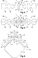
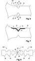
- the pre-cut-out binocular 62 shown in FIG. figure 5 thus comprises four notches 64, 66 that are symmetrical two by two with respect to the transverse median T and longitudinal L planes.
- the notches 64 are disposed on the side opposite the notches 66 with respect to the longitudinal median plane T.
- Each notch 64 , 66 has an outer surface 68 to be treated by ion bombardment.
- This material bridge 67 is generally between 0.02 and 0.2 mm, preferably between 0.05 and 0.1 mm in order to guarantee easy separation of the members 10 while ensuring good cohesion of the pre-cut binoculars in the case. process
- each outer surface 68 includes one of the front portions 28, 29 and one of the side portions 26, 27 defining one of the wiping edges 22 , 24.
- This outer surface 68 has a general V shape.
- Each naked and untreated member 48A, 48B of the binocular 38 is movable relative to the other member 48A, 48B bare and untreated between an open position of the notch in which the outer surface 68 is exposed to the treatment by ion bombardment and a closing position of the notch in which the outer surface 68 of the notch is masked.
- each bare and untreated member 10 is moved relative to each other by means of the device. 46.
- the positioning device 46 is arranged so that the outer surface 68 of the notches 64 to be treated by ion bombardment is exposed to the ion beam generated by the device 44.
- the device 46 comprises a support 70 having a support surface 72 of the bearing surface 60 of the central leg and two support surfaces 74 of each bearing surface 58 of each heel 11.
- Each support surface 74 forms a predetermined angle with the surface 72. This angle is between 20 ° and 60 °, in this case the angle is substantially equal to 45 °.
- each outer surface 68 of each notch 66 defines an angle substantially equal to 45 °.
- a first step of treatment by ion bombardment is treated by ion bombardment the binocular 38 including the outer surface 68 of the notches 64 in the open position.
- the angle of incidence of the ion beam with respect to the external surface to be treated is between 0 and 45 °, here 20 °.
- the binocular 38 is moved continuously, by means of guiding and moving means, substantially parallel to the direction X with respect to the device 44 so as to expose the entirety of the external surface 68 of the devices. Notches 64.
- the displacement of the binocular 38 relative to the device 44 is performed in a vacuum chamber in which the pressure is substantially equal to 10 -3 mbar.
- the speed of movement is such that the treatment time per cm 2 of binoculars 38 is substantially equal to 2 seconds.
- the ion bombardment is carried out by micro-sources which may be based, for example, on a filament technology or on a technology type ECR (Electron Cylonic Resonance) with multi-energy ions of nitrogen.
- these micro-sources allow to design a device whose size is small.
- several ion beams can be used in series so as to obtain a treatment intensity adapted to the speed of movement of the binocular 38.
- the number of sources and the speed of displacement of the binoculars 38 can be implanted in the material between 10 14 and 10 16 ions / cm 2 .
- the extraction voltage is between 35kV and 100kV, here 50 kV.
- Part 29 of the outer surface 25 from which the material M extends has a surface thickness with increased crosslinking.
- the binocular 38 is turned over with respect to the longitudinal median plane T by means of the device 43 for reversing the binoculars 38.
- a second step of positioning the binocular 38 similar to the first positioning step the binocular 38 is positioned relative to the device 45 for generating an ion beam.
- each naked member is moved relative to each other by means of the displacement device 47 so that the outer surface 68 of the nicks 66 to be treated by ion bombardment is exposed to the ion beam generated. by the device 45.
- the binoculars 38 are treated by ion bombardment, in particular the external surfaces 68 of the notches 66 in the open position.
- Part 28 of the outer surface 25 from which the material M extends has a surface thickness with increased crosslinking.
- the coating 30 is deposited on the outer surface 25 of the member 10.
- each precursor 48A, 48B is separated from the sacrificial connecting element 50 by means of the device 48 which ruptures the material bridge 67.
- the sacrificial element 50 between the wiping members 48A, 48B is optional, it allows in particular better guidance of the binocular 38.
- there is no element 50 there is only one only pre-cut between each each wiper member 48A, 48B on either side of the longitudinal plane L. It is also possible to treat the entire lip, see the entire surface of the part and not only the parts in the vicinity of the cuts.
- Sample A corresponds to a wiper member manufactured by the process according to the invention described above but during which the coating step was omitted.
- Sample B corresponds to a body without a coating made during a process in which the notch is cut after ionically bombarding the binocular from which the organ is derived.
- Sample C corresponds to a wiper member 10 made by the process according to the invention described above.
- Sample D corresponds to an organ comprising a coating as described above and manufactured during a process in which the notch is cut after ionically bombarding the binocular from which the organ is derived.
- the binocular is ionically bombarded under a nitrogen atmosphere at an extraction voltage of 50 kV at a working pressure of 10 -3 bar and with an angle of incidence of 10 °.
- the acoustic performances of the samples are tested by means of a test making it possible to quantify the occurrences of vibration noise of each sample displaced in translation on a flat pane at speeds and by applying predetermined pressures simulating conditions of use under lubricated conditions. .
- the test is described in detail in the publication "Wiper rubber blade squeal noise test: a methodology for its characterization and influential factors study” by A. Sanon and presented at the "Automotive and Rail comfort, acoustics, vibrations & thermal issues” conference held in October 2010.
- the acoustic performances are tested on new samples (occurrence of the initial noise) and on worn samples (occurrence of the noise after 50,000 cycles).
- the wear of the samples is carried out by means of an alternating friction machine moving an ice square of 10 cm 2 over a course of 10 cm.
- the sample is positioned on the ice with a pressure of 15g.cm -1 and the speed is 45 roundtrips (one cycle) per minute.
- Table 1 Comparison of vibration noise occurrences obtained with different wipers.
- Table 1 shows that, when ionically bombarding the notch, the occurrence of the vibration noise decreases.
- Table 1 shows that the presence of a coating, in particular a graphite coating, also reduces the occurrence of vibration noise. .
- a coating improves the sound comfort of the occupant of the vehicle regardless of the wear of the body.
- Table 1 shows that the combination of the order of the pre-slit and ion bombardment steps and the use of the coating has a synergistic effect of reducing the occurrence of vibration noise. This synergistic effect is particularly present when the member has advanced wear. Indeed, without coating, the reduction of the vibration noise with respect to the sample B is of the order of 25-30% for the sample A manufactured with a process during which the notch is ionically bombarded. With a coating, the reduction of the vibration noise with respect to the sample D is of the order of 50% for the sample C manufactured with a process during which the notch is ionically bombarded.
- Samples A to D are worn using the alternative friction machine described in Example 1. Wear is monitored hourly. The number of cycles necessary to obtain a used volume of 0.5 mm 3 is determined . This volume corresponds to significant wear beyond which the wiping performance is degraded. Table 2: Comparison of wear resistances (number of cycles to achieve 0.5mm3 of wear) obtained with different wipers.
- Table 1 shows that when ionically bombarding the notch, the wear resistance increases.
- Table 1 shows that the presence of a coating, in particular a graphite coating, improves the wear resistance.
- a coating improves the strength of the organ.
- Table 1 shows that the combination of the order of the pre-slit and ion bombardment steps and the use of the coating has a synergistic effect of increasing the wear resistance.
- the increase of the wear resistance with respect to the sample B is of the order of 30% for the sample A manufactured with a method during which the notch is ionically bombarded.
- the increase of the wear resistance with respect to the sample D is of the order of 50% for the sample C manufactured with a process during which the notch is ionically bombarded.
- Table 2 Comparison of wear resistances (number of cycles to achieve 0.5mm3 of wear) obtained with different wipers.
- Table 1 shows that when ionically bombarding the notch, the wear resistance increases.
- Table 1 shows that the presence of a coating, in particular a graphite coating, improves the wear resistance.
- a coating improves the strength of the organ.
- Table 1 shows that the combination of the order of the pre-slit and ion bombardment steps and the use of the coating has a synergistic effect of increasing the wear resistance.
- the increase of the wear resistance with respect to the sample B is of the order of 30% for the sample A manufactured with a method during which the notch is ionically bombarded.
- the increase of the wear resistance with respect to the sample D is of the order of 50% for the sample C manufactured with a process during which the notch is ionically bombarded.
Landscapes
- Chemical & Material Sciences (AREA)
- Medicinal Chemistry (AREA)
- Mechanical Engineering (AREA)
- General Chemical & Material Sciences (AREA)
- Health & Medical Sciences (AREA)
- Chemical Kinetics & Catalysis (AREA)
- Engineering & Computer Science (AREA)
- Polymers & Plastics (AREA)
- Organic Chemistry (AREA)
- Treatments Of Macromolecular Shaped Articles (AREA)
- Laminated Bodies (AREA)
- Lining Or Joining Of Plastics Or The Like (AREA)
- Manufacture Of Macromolecular Shaped Articles (AREA)
Description
La présente invention concerne un organe d'essuyage d'une surface à essuyer, en particulier une lame de balai d'essuie-glace pour véhicule automobile, l'organe comportant un matériau à base d'élastomère(s) présentant un traitement de surface spécifique. L'invention concerne également un procédé d'obtention de cet organe et l'utilisation de celui-ci.The present invention relates to a wiper member for a surface to be wiped, in particular a wiper blade for a motor vehicle wiper, the member comprising an elastomer-based material (s) having a surface treatment specific. The invention also relates to a method for obtaining this organ and the use thereof.
Dans le domaine des matériaux techniques à base d'élastomères, la recherche s'oriente souvent vers une amélioration des propriétés mécaniques et/ou de l'aspect de surface des pièces mises en forme à partir de ces matériaux.In the field of elastomeric-based technical materials, research is often directed towards improving the mechanical properties and / or the surface appearance of the pieces shaped from these materials.
Dans le cas de lames d'essuyage pour balai d'essuie-glace de véhicule automobile, ces lames doivent présenter certaines caractéristiques, en particulier en surface, permettant un essuyage efficace du pare-brise sur lequel elles se déplacent. Ces lames doivent également présenter un confort sonore en utilisation pour l'occupant du véhicule automobile, c'est-à-dire éviter de générer des ondes sonores, donc du bruit.In the case of wiper blades for wiper blades of a motor vehicle, these blades must have certain characteristics, especially at the surface, allowing effective wiping of the windshield on which they move. These blades must also have a sound comfort in use for the occupant of the motor vehicle, that is to say, avoid generating sound waves, so noise.
On connait de l'état de la technique un procédé de fabrication d'une lame d'essuyage en matériau à base d'élastomère(s) dans lequel on traite la lame par bombardement ionique afin de durcir le matériau à base d'élastomère(s) sur une épaisseur superficielle. On citera par exemple
Toutefois, ce traitement par bombardement ionique est coûteux et présente des difficultés de mise en oeuvre car on bombarde séparément chaque lame, notamment si on souhaite localiser le traitement sur la tranche d'essuyage.However, this treatment by ion bombardment is expensive and presents implementation difficulties because each blade is bombarded separately, especially if it is desired to locate the treatment on the wiping wafer.
Or, dans un dispositif de traitement de jumelle avec une refente réalisée après le traitement de surface, on ne bénéficie plus de l'avantage obtenu en traitant tout ou partie de la tranche d'essuyage qui est la partie en contact avec le pare-brise.However, in a binocular treatment device with a splitting performed after the surface treatment, it no longer benefits from the advantage obtained by treating all or part of the wiping wafer which is the part in contact with the windshield .
En outre, il serait souhaitable de disposer d'un traitement des lames efficace permettant de limiter notablement, voire d'éliminer la génération d'ondes sonores par celles-ci lors de leur utilisation.In addition, it would be desirable to have an effective blade treatment to significantly reduce or eliminate the generation of sound waves by them during their use.
L'invention a pour but de fournir un procédé de fabrication plus simple et un organe permettant d'améliorer le confort sonore de l'occupant du véhicule.The invention aims to provide a simpler manufacturing process and a member for improving the sound comfort of the occupant of the vehicle.
A cet effet, l'invention a pour objet un procédé de fabrication d'un organe selon la revendication 1.For this purpose, the subject of the invention is a method for manufacturing an organ according to claim 1.
Le procédé selon l'invention permet de traiter de façon continue une jumelle d'organes d'essuyage. Il n'est pas nécessaire, contrairement au procédé de l'état de la technique de traiter individuellement chaque organe, d'où un gain de temps. Chaque entaille permet ainsi un traitement de surface de la tranche d'essuyage sans avoir à désolidariser les deux organes l'un de l'autre.The method according to the invention makes it possible to continuously treat a binocular of wiping members. It is not necessary, unlike the method of the state of the art to treat each organ individually, resulting in a saving of time. Each notch thus allows a surface treatment of the wiping wafer without having to separate the two bodies from one another.
En outre, grâce au procédé de l'invention, il est possible de traiter facilement la surface externe de l'entaille qui est destinée à former la surface qui sera en contact avec la surface à essuyer. En effet, le traitement de la surface de l'entaille permet de générer une réticulation accrue sur une épaisseur superficielle de la surface externe. On garantit ainsi une résistance accrue sur les parties de l'organe d'essuyage les plus sollicitées mécaniquement.In addition, thanks to the method of the invention, it is possible to easily treat the external surface of the notch which is intended to form the surface which will be in contact with the surface to be wiped. Indeed, the treatment of the surface of the notch makes it possible to generate an increased crosslinking on a superficial thickness of the external surface. This guarantees an increased resistance on the parts of the wiper member most mechanically stressed.
Le traitement par bombardement ionique s'effectue à l'aide d'un dispositif comportant un générateur d'ions et un applicateur d'ions tels que par exemple ceux décrits dans
L'applicateur d'ions comprend habituellement des moyens choisis par exemple parmi des lentilles électrostatiques de mise en forme de faisceau d'ions, un diaphragme, un obturateur un collimateur un analyseur de faisceau d'ions et un contrôleur de faisceau d'ions.The ion applicator usually comprises means selected for example from electrostatic ion beam shaping lenses, a diaphragm, a shutter, a collimator, an ion beam analyzer, and an ion beam controller.
Le générateur d'ions comprend habituellement des moyens choisis par exemple parmi une chambre d'ionisation, une source d'ions à filament ou à résonance cyclotronique électronique ou un système à plasma impulsionel, un accélérateur d'ions et dans certains cas, un séparateur d'ions.The ion generator usually comprises means selected for example from an ionization chamber, a source of electron cyclotron resonance or electron cyclotron resonance ions or an impulse plasma system, an ion accelerator and in some cases a separator. ion.
Le bombardement ionique est généralement réalisé sous vide. Par exemple,
Avantageusement, le bombardement ionique est effectué au moyen de faisceaux d'ions mono ou multi-énergie(s) issus de gaz tels que l'hélium, le néon, le krypton, l'argon, le xénon, le dioxygène ou le diazote, seuls ou en mélange. De préférence, le diazote et/ou l'helium, seuls ou en mélange, préférentiellement le diazote.Advantageously, the ion bombardment is carried out by means of single or multi-energy ion beams derived from gases such as helium, neon, krypton, argon, xenon, dioxygen or dinitrogen, alone or in mixture. Preferably, the dinitrogen and / or the helium, alone or as a mixture, preferably the dinitrogen.
De préférence, le bombardement d'ions s'effectuera à une pression comprise entre 1 mbar et 10-5mbar, de préférence, entre 10-2 mbar et 5.10-4 mbar, et transmettant au matériau une énergie de l'ordre de 0,1 à 100 keV, de préférence de 0,3 à 30 keV.Preferably, the ion bombardment will take place at a pressure of between 1 mbar and 10 -5 mbar, preferably between 10 -2 mbar and 5 × 10 -4 mbar, and transmitting to the material an energy of the order of 0.1 to 100 keV, preferably of 0.3 to 30 keV .
Selon un exemple avantageux, on implante, dans le matériau, entre 1014 et
1016 ions/cm2.According to an advantageous example, the material is implanted between 10 14 and
10 16 ions / cm 2 .
Par « élastomère(s) », on entend un polymère présentant des propriétés « hyper-élastiques », obtenues après réticulation du polymère. Ces élastomères comprennent des élastomères naturels ou synthétiques, seuls ou en mélange, en particulier les élastomères choisis parmi le groupe constitué par les caoutchoucs naturels (NR), les polychloroprènes (CR), les éthylène-propylène-diène monomères (EPDM), les caoutchoucs nitriles (NBR, HNBR, XNBR), les polybutadiènes (BR), les caoutchoucs butyles, les épichlorhydrines (ECO/GECO), les copolymères d'éthylène-acrylate (type VAMAC), les polyuréthanes (PU), les élastomères fluorés et les élastomères silicone (VMQ/FMQ). Ces élastomères peuvent être utilisés seul ou en mélange. A titre d'exemple, on cite les mélanges NR/EPDM, NR/CR, EPDM/PP ou d'autres mélanges connus par l'homme de métier.By "elastomer (s)" is meant a polymer having "hyper-elastic" properties, obtained after crosslinking the polymer. These elastomers comprise natural or synthetic elastomers, alone or as a mixture, in particular the elastomers chosen from the group consisting of natural rubbers (NR), polychloroprenes (CR), ethylene-propylene-diene monomers (EPDM), rubbers nitriles (NBR, HNBR, XNBR), polybutadienes (BR), butyl rubbers, epichlorohydrins (ECO / GECO), ethylene-acrylate copolymers (VAMAC type), polyurethanes (PU), fluorinated elastomers and silicone elastomers (VMQ / FMQ). These elastomers can be used alone or in mixture. By way of example, mention is made of the NR / EPDM, NR / CR, EPDM / PP mixtures or other mixtures known to those skilled in the art.
De préférence, les élastomères sont choisi parmi le groupe constitué par les NR, les EPDM, les CR et les mélanges à base de ces élastomères.Preferably, the elastomers are chosen from the group consisting of NRs, EPDMs, CRs and mixtures based on these elastomers.
Par «à base de», on entend un matériau comportant au moins 10% d'élastomère(s), de préférence, au moins 20%, plus préférentiellement, au moins 35%. En effet, le matériau comprend au moins un élastomère de base, synthétique ou naturel, ainsi que différentes charges et/ou additifs pour assurer ses performances mécaniques et sa compatibilité avec des environnements climatiques variés.By "based on" is meant a material comprising at least 10% elastomer (s), preferably at least 20%, more preferably at least 35%. Indeed, the material comprises at least one basic elastomer, synthetic or natural, and different fillers and / or additives to ensure its mechanical performance and compatibility with various climatic environments.
Les charges utilisées pour le matériau sont généralement du noir de carbone, du graphite, de la silice, du talc ou une craie ainsi que leurs dérivés et/ou mélanges.The fillers used for the material are generally carbon black, graphite, silica, talc or chalk and their derivatives and / or mixtures.
Les additifs comprennent entre autres des agents de protection, par exemple des dérivés des paraphénylènediamines qui piègent les UV. Les additifs comprennent également des cires qui migrent en surface pour protéger le matériau. De plus, les additifs peuvent comprendre des plastifiants pour améliorer la tenue à froid et la mise en oeuvre de l'élastomère. Les plastifiants les plus couramment utilisés sont l'huile naphténique, l'huile aromatique, l'huile parrafinique ou l'huile ester. Les additifs comprennent un système de vulcanisation, par exemple comprenant du soufre et/ou différentes molécules améliorant l'efficacité de la réaction ou des dérivés de peroxydes.The additives include, inter alia, protective agents, for example para-phenylenediamine derivatives which trap UV. The additives also include waxes that migrate to the surface to protect the material. In addition, the additives may comprise plasticizers to improve the cold resistance and the use of the elastomer. The most commonly used plasticisers are naphthenic oil, aromatic oil, paraphenic oil or ester oil. The additives comprise a vulcanization system, for example comprising sulfur and / or different molecules improving the reaction efficiency or peroxide derivatives.
Avantageusement, on dépose un revêtement visant à réduire la friction sur une surface externe de la jumelle d'organes après l'étape de traitement par bombardement ionique.Advantageously, a coating is deposited to reduce friction on an outer surface of the organ binocular after the ion bombardment treatment step.
Ainsi, on dépose, sur le matériau à base d'élastomère, un revêtement comprenant au moins un liant et/ou au moins une charge. Ce revêtement permet de réduire la friction entre l'organe d'essuyage et la surface à essuyer et donc de maintenir la qualité d'essuyage du balai plus longtemps. A titre d'exemple, le revêtement utilisé pour être celui défini dans l'exemple du brevet
Le ou les liants comprennent un polymère dont la fonction est de retenir les charges glissantes, tel que le graphite ou autre particules lubrifiantes, sur l'organe d'essuyage. Il est incorporé sous forme de suspension, de dispersion ou de poudre en fonction du mode d'application du revêtement. Le polymère du liant est choisi parmi les dérivés acryliques, les dérivés styrène acrylique, les acrylonitriles et leurs dérivés, les polyuréthanes de type ester ou éther et leurs leurs dérivés et le polychlorure de vinyle (PVC). Le liant peut également comprendre au moins un élastomère fluoré ainsi que des silicones ou siloxanes. Les latex élastomériques peuvent également être employés ainsi que les poudres de polyamide, de polyéthylène ou de polypropylène. Le liant peut également comprendre au moins un agent de réticulation du type mélamines, isocyanate ou époxy pour conférer des propriétés de résistance mécanique et chimique accrues au revêtement ainsi que de la cire pour améliorer l'imperméabilité du film formé par les liants.The binder or binders comprise a polymer whose function is to retain the sliding charges, such as graphite or other lubricating particles, on the wiper member. It is incorporated as a suspension, dispersion or powder depending on the application of the coating. The binder polymer is chosen from acrylic derivatives, styrene acrylic derivatives, acrylonitriles and their derivatives, ester or ether polyurethanes and their derivatives and polyvinyl chloride (PVC). The binder may also comprise at least one fluorinated elastomer as well as silicones or siloxanes. Elastomeric latexes can also be used as well as powders of polyamide, polyethylene or polypropylene. The binder may also comprise at least one crosslinking agent of melamine, isocyanate or epoxy type to impart increased mechanical and chemical resistance properties to the coating and wax to improve the impermeability of the film formed by the binders.
La ou les charges introduites dans le revêtement permettent d'abaisser le coefficient de friction de l'organe d'essuyage. Usuellement, on utilisera du graphite, du disulfure de molybdène (MoS2), du talc, du polytétrafluoroéthylène (PTFE) tel que celui commercialisé sous la marque Teflon®, des particules de polyéthyène à poids moléculaire « ultra haut » (Ultra High Molecular Weight Polyethylene - UHMWPE), du polyéthylène, du polypropylène, des silicones, des charges nanostructurées comme les fullerènes, les nanotubes de carbones (CNT) ou leurs mélanges.The charge or charges introduced into the coating make it possible to lower the coefficient of friction of the wiper member. Usually, use will be made of graphite, molybdenum disulphide (MoS 2 ), talc, polytetrafluoroethylene (PTFE) such as that marketed under the trademark Teflon®, ultra high molecular weight polyethylene particles (Ultra High Molecular Weight). Polyethylene - UHMWPE), polyethylene, polypropylene, silicones, nanostructured fillers such as fullerenes, carbon nanotubes (CNT) or their mixtures.
L'incorporation de ces charges dans une matrice liquide sera facilitée par des agents de dispersion comme par exemple des polyacrylates. Des agents épaississants évitant leur sédimentation sont également souvent requis.The incorporation of these fillers in a liquid matrix will be facilitated by dispersing agents such as polyacrylates. Thickening agents that prevent sedimentation are also often required.
De préférence, le revêtement comprend du graphite. Le graphite est, par exemple, sous forme de poudre dispersée dans une matrice. La présence de graphite permet d'améliorer la réduction de la friction entre l'organe et la surface à essuyer et donc d'améliorer le confort sonore de l'occupant du véhicule.Preferably, the coating comprises graphite. The graphite is, for example, in powder form dispersed in a matrix. The presence of graphite makes it possible to improve the reduction of the friction between the body and the surface to be wiped and thus to improve the sound comfort of the occupant of the vehicle.
Selon une caractéristique optionnelle du procédé, les organes de la jumelle étant mobiles l'un par rapport à l'autre entre une position d'ouverture de l'entaille dans laquelle la partie de la surface externe est exposée au traitement par bombardement ionique et une position de fermeture de l'entaille dans laquelle la partie de la surface externe est masquée, on traite par bombardement ionique la partie de la surface externe de l'entaille dans la position d'ouverture.According to an optional feature of the method, the members of the binocular being movable relative to each other between an open position of the notch in which the portion of the outer surface is exposed to the ion bombardment treatment and a closing position of the notch in which the portion of the outer surface is masked, is treated by ion bombardment the portion of the outer surface of the notch in the open position.
Ainsi, en positionnant l'entaille en position d'ouverture, on expose la plus grande surface possible de l'entaille au bombardement ionique. On traite ainsi aussi bien l'intérieur de l'entaille que les portions des faces latérales de l'organe situées au voisinage de l'entaille.Thus, by positioning the notch in the open position, the largest possible area of the notch is exposed to ion bombardment. The inside of the notch is thus treated as well as the portions of the lateral faces of the organ located at neighborhood of the notch.
De préférence, après l'étape de bombardement ionique ou de dépôt du revêtement, le procédé comporte une étape de refente de la jumelle. On obtient alors deux organes d'essuyage indépendants.Preferably, after the ion bombardment or coating deposition step, the method comprises a step of slitting the binoculars. We then obtain two independent wipers.
L'invention a également pour objet une jumelle d'organes d'essuyage selon la revendication 6.The invention also relates to a binocular of wipers according to claim 6.
La réticulation est définie comme une densification des liaisons entre les chaines macromoléculaires constituant le polymère. Par « réticulation accrue », on entend un degré de réticulation supérieur à celui du ou des polymère(s) présent(s) dans le reste du matériau. En général, le degré de réticulation du ou des polymère(s) présent(s) dans le reste du matériau correspondra au degré de réticulation obtenu dans les conditions usuelles de vulcanisation ou de réticulation chimique du ou des polymère(s), c'est-à-dire, sans traitement spécifique additionnel du ou des polymère(s). On peut également utiliser le terme « sur-réticulé ».Crosslinking is defined as a densification of the bonds between the macromolecular chains constituting the polymer. By "increased crosslinking" is meant a degree of crosslinking greater than that of the polymer (s) present in the rest of the material. In general, the degree of crosslinking of the polymer (s) present in the rest of the material will correspond to the degree of crosslinking obtained under the usual conditions of vulcanization or chemical crosslinking of the polymer (s), it is that is, without additional specific treatment of the polymer (s). The term "over-crosslinked" can also be used.
Pour un polymère donné, le degré de réticulation D peut être mesuré par la solubilité dans un solvant du polymère ou des polymères. Le polymère étant soluble dans le solvant, les parties réticulées seront, elles, insolubles.For a given polymer, the degree of crosslinking D can be measured by the solubility in a solvent of the polymer or polymers. Since the polymer is soluble in the solvent, the crosslinked portions will be insoluble.
En considérant uniquement la masse de l'épaisseur superficielle du polymère : 
Par exemple, le degré de réticulation du NBR peut être mesuré comme suit : 
Selon un exemple avantageux, le degré de réticulation de l'élastomère de l'organe dans l'épaisseur superficielle est supérieur de 10% à celui du ou des polymère(s) présent(s) dans le reste du matériau à base d'élastomère, de préférence, de 50%, plus préférentiellement, de 95%.According to an advantageous example, the degree of crosslinking of the organ elastomer in the superficial thickness is 10% greater than that of the polymer (s) present in the rest of the elastomer-based material. preferably 50%, more preferably 95%.
La réticulation du matériau peut être mise en évidence également par DSC (Differential Scanning Calorimetry). Une comparaison du matériau traité et non traité met en évidence que l'accroissement du degré de réticulation du matériau a pour effet de faire disparaître la température de transition vitreuse « Tg » (changement endothermique de capacité calorifique).The crosslinking of the material can also be demonstrated by DSC (Differential Scanning Calorimetry). A comparison of the treated and untreated material shows that the increase in the degree of crosslinking of the material has the effect of eliminating the glass transition temperature "T g " (endothermic change in heat capacity).
La réticulation accrue est obtenue au moyen d'un bombardement ionique d'énergie suffisante pour générer des recombinaisons dans la matière et accroître les pontages covalents. On obtient une réticulation dont l'intensité de réticulation est supérieure à celle obtenue par d'autres moyens comme la réticulation au moyen d'un agent chimique. Par ailleurs, elle est indépendante de la nature chimique du polymère à irradier. Par exemple, elle sera efficace aussi bien sur un polymère à base de silicone que sur un polymère acrylique ou un polyuréthane.The increased crosslinking is achieved by ion bombardment of energy sufficient to generate recombinations in the material and increase covalent bridging. Crosslinking is obtained whose crosslinking intensity is greater than that obtained by other means such as crosslinking by means of a chemical agent. Moreover, it is independent of the chemical nature of the polymer to be irradiated. For example, it will be effective on both a silicone polymer and an acrylic polymer or polyurethane.
On entend par « épaisseur superficielle », une épaisseur localisée en surface du matériau. Avantageusement, cette épaisseur est inférieure à 3 µm en partant de la surface externe du revêtement, plus préférentiellement inférieure 1 µm. Selon un autre exemple avantageux, l'épaisseur superficielle est égale ou supérieure à 3 µm et inférieure à 5 µm.The term "superficial thickness" means a thickness located at the surface of the material. Advantageously, this thickness is less than 3 microns from the outer surface of the coating, more preferably less than 1 micron. According to another advantageous example, the superficial thickness is equal to or greater than 3 μm and less than 5 μm.
La réticulation accrue de cette épaisseur superficielle permet une augmentation de la dureté et de la résistance à l'abrasion en particulier du revêtement et/ou du matériau. Un des effets de cette augmentation de dureté est de réduire le bruit que l'organe est susceptible de produire en frottant sur la surface à essuyer. L'organe selon l'invention permet donc d'améliorer le confort sonore de l'occupant du véhicule.The increased cross-linking of this superficial thickness makes it possible to increase the hardness and abrasion resistance, in particular of the coating and / or the material. One of the effects of this increase in hardness is to reduce the noise that the organ is likely to produce by rubbing on the surface to be wiped. The member according to the invention therefore makes it possible to improve the sound comfort of the occupant of the vehicle.
Un autre effet de cette réticulation accrue est d'augmenter la résistance à l'abrasion de l'organe selon l'invention et par conséquent sa durée de vie. De plus, l'épaisseur superficielle présentant une réticulation accrue forme une barrière qui empêche la migration d'espèces chimiques, notamment les espèces utilisées dans les produits lave-glace ou lave-vitre, vers l'intérieur de l'organe. Or, ces espèces chimiques peuvent dégrader le matériau à base d'élastomère(s).Another effect of this increased crosslinking is to increase the abrasion resistance of the organ according to the invention and consequently its service life. In addition, the surface thickness having increased crosslinking forms a barrier which prevents the migration of chemical species, especially the species used in the windshield washer or window washer, to the interior of the organ. However, these chemical species can degrade the material based on elastomer (s).
L'invention a pour autre objet un organe d'essuyage comportant un matériau à base d'élastomère(s), susceptible d'être obtenue par le procédé tel que défini ci-dessus.Another object of the invention is a wiping member comprising a material based on elastomer (s) that can be obtained by the process as defined above.
Des organes d'essuyage plus particulièrement visés par l'invention sont une lame de balai d'essuie-glace.Wiper members more particularly targeted by the invention are a blade wiper blade.
L'invention a pour objet un dispositif d'essuyage comportant un organe d'essuyage tel que défini ci-dessus. Il s'agit plus particulièrement d'une lame de balai d'essuie-glace, en particulier pour véhicule automobile.The invention relates to a wiper device comprising a wiper member as defined above. It is more particularly a wiper blade, particularly for a motor vehicle.
Par exemple, une lame de balai d'essuyage est usuellement composée de trois éléments :
- une lèvre assurant le contact avec le pare-brise et assurant le joint d'étanchéité permettant l'essuyage de l'eau,
- un talon de forme généralement rectangulaire permettant d'insérer la lame dans le balai et,
- une charnière (optionnelle) formée par une fine bande de caoutchouc située entre la lèvre et le talon et assurant le bon positionnement de la lèvre sur le pare-brise, notamment lors du changement de direction du balai aux points de retournement.
- a lip ensuring contact with the windshield and providing the seal for wiping the water,
- a generally rectangular shaped heel for inserting the blade into the broom and,
- a hinge (optional) formed by a thin rubber strip located between the lip and the heel and ensuring the proper positioning of the lip on the windshield, especially when changing the direction of the broom at turning points.
On notera que le balai peut être, soit un balai classique, soit un balai plat.Note that the broom may be either a conventional broom or a flat broom.
Par « balai classique », on entend un balai dons la répartition de pression imprimée par le bras supportant le balai est assurée par des palonniers répartis le long du balai.By "conventional broom" means a broom donations the pressure distribution printed by the arm supporting the broom is provided by spreaders distributed along the broom.
Alors que pour un « balai plat », la répartition de pression imprimée par le bras supportant le balai est assurée par une vertèbre métallique ayant une courbure et une pression calculée. Ainsi, on peut supprimer les palonniers du bras ce qui permet une réduction de la hauteur du balai.While for a "flat blade", the pressure distribution printed by the arm supporting the blade is provided by a metal vertebra having a curvature and a calculated pressure. Thus, one can remove the pedals of the arm which allows a reduction of the height of the blade.
L'invention concerne également l'utilisation de l'organe tel que défini ci-dessus pour diminuer les nuisances sonores pouvant être produites lors de la friction d'un organe d'essuyage avec la surface à essuyer.The invention also relates to the use of the member as defined above to reduce the noise that can be produced during the friction of a wiper member with the surface to be wiped.
En effet, lorsque l'organe d'essuyage se déplace sur la surface à essuyer, par exemple sur un pare-brise ou contre une vitre, les frictions entre l'organe et la surface à essuyer peuvent générer des ondes sonores qui nuisent au confort des occupants du véhicule.Indeed, when the wiper member moves on the surface to be wiped, for example on a windshield or against a glass, friction between the body and the surface to be wiped can generate sound waves that affect comfort occupants of the vehicle.
Avantageusement, les organes décrits précédemment permettent de réduire ces bruits. En effet, ces organes se déforment moins sous les forces de friction car ils sont plus durs et que la friction entre l'organe et la surface à essuyer est optimisée.Advantageously, the organs described above make it possible to reduce these noises. Indeed, these bodies are deformed less under the friction forces because they are harder and the friction between the body and the surface to be wiped is optimized.
Un tel procédé peut être mis en oeuvre par une Installation de traitement par bombardement ionique d'une jumelle d'organes d'essuyage joints entre eux, la jumelle étant pré-refendue par une entaille visant à permettre une séparation ultérieure des organes l'un de l'autre, caractérisé en ce que l'installation comprend:
- un dispositif de génération d'un faisceau d'ions en vue d'effectuer un bombardement ionique, et
- un dispositif de positionnement d'au moins une partie d'une surface externe de l'entaille de la jumelle par rapport au dispositif de génération du faisceau d'ions.
- a device for generating an ion beam for ion bombardment, and
- a device for positioning at least a part of an external surface of the notch of the binocular with respect to the device for generating the ion beam.
D'autres caractéristiques et avantages de l'invention seront décrits dans les exemples qui suivent.Other features and advantages of the invention will be described in the examples which follow.
L'invention sera mieux comprise à la lecture de la description qui va suivre, donnée uniquement à titre d'exemple non limitatif et faite en se référant aux dessins dans lesquels :
- les
figures 1a et 1b présentent respectivement des vues schématiques en perspective d'un balai d'essuie-glace classique et d'un balai d'essuie-glace plat selon l'invention; - la
figure 2 est une vue en perspective d'une coupe d'un organe d'essuyage selon l'invention; - la
figure 3 illustre une installation de fabrication d'un organe d'essuyage permettant la mise en oeuvre selon l'invention; - la
figure 4 est une vue en coupe transversale d'une jumelle d'organes d'essuyage avant pré-découpage, - la
figure 5 est une vue en coupe transversale d'une jumelle d'organes d'essuyage après pré-découpage, - la
figure 6 est une vue de détail de la jumelle de lafigure 5 , - la
figure 7 est une vue de la jumelle de lafigure 6 après une étape de bombardement ionique, - la
figure 8 est une vue en coupe transversale d'une jumelle d'organes d'essuyage pendant une étape de bombardement ionique - la
figure 9 est une vue en coupe transversale d'une jumelle d'organes d'essuyage après pré-découpage, sans élément sacrificiel.
- the
Figures 1a and 1b present respectively schematic perspective views of a conventional windscreen wiper blade and a flat windscreen wiper blade according to the invention; - the
figure 2 is a perspective view of a section of a wiper member according to the invention; - the
figure 3 illustrates a manufacturing facility of a wiper member for implementation according to the invention; - the
figure 4 is a cross-sectional view of a binocular of wipers before pre-cutting, - the
figure 5 is a cross-sectional view of an organ binocular wiping after pre-cutting, - the
figure 6 is a detail view of the binoculars of thefigure 5 , - the
figure 7 is a view of the twin of thefigure 6 after an ion bombardment step, - the
figure 8 is a cross sectional view of a binocular of wipers during an ion bombardment step - the
figure 9 is a cross-sectional view of a binocular of wipers after pre-cutting, without sacrificial element.
On a représenté sur les
On a représenté sur la
L'organe 10 comprend un matériau M à base d'élastomère(s), par exemple du caoutchouc naturel présentant une surface externe 25. Chaque face latérale 18, 20 comprend respectivement une partie latérale 26, 27 sur laquelle le matériau à base d'élastomère(s) comporte une épaisseur superficielle E présentant une réticulation accrue. De façon analogue, la face frontale 16 comprend deux parties frontales 28, 29 sur laquelle le matériau à base d'élastomère(s) comporte une épaisseur superficielle E' présentant une réticulation accrue. De préférence, E est sensiblement égal à E'. L'intersection de chaque partie 26, 27 avec chaque partie 28, 29 définit respectivement chaque arête 22, 24 d'essuyage.The
L'organe 10 comprend également un revêtement 30 d'au moins une partie de la surface externe 25 de la lèvre 14. Le revêtement 30 vise à réduire la friction de l'organe 10 avec la surface à essuyer.The
On va maintenant décrire un procédé de fabrication de l'organe 10 de la
On a représenté sur la
Dans une étape d'extrusion classique, on extrude le matériau à base d'élastomère(s) afin d'obtenir la jumelle 38 au moyen du dispositif d'extrusion 36. La jumelle 38 est venue de matière dans le matériau à base d'élastomère(s). Après extrusion, on vulcanise la jumelle 38.In a conventional extrusion step, the elastomer-based material (s) is extruded to obtain the
On a représenté sur la
Puis, dans une étape de pré-refente, on pré-découpe l'élément de liaison 50 de part et d'autre du plan longitudinal L entre chaque organe d'essuyage 48A, 48B nu et non traité et le jambage central 52 au moyen du dispositif de pré-découpage 40 comprenant par exemple, des lames de pré-découpe fixe, des lames rotatives ou des lames de rasoir. La précision du dispositif de pré-découpage 40 présente une précision de 0,10 mm, voire inférieure à 0,05 mm ce qui permet d'ajuster la profondeur des entailles. L'étape de pré-découpe est réalisée de façon continue par déplacement de la jumelle 38 au contact des lames des dispositifs 40, 41. A cet effet, les moyens de déplacement de la jumelle 38 comprennent des rouleaux d'entraînement de la jumelle.Then, in a pre-slitting step, the connecting
On obtient alors la jumelle pré-découpée 62 représentée à la
Ces entailles 64, 66 sont séparées par un «pont» de matière résiduel 67 suffisamment résistant pour permettre une manipulation de la jumelle 38 sans que les deux organes 10 ne se séparent. Ce pont de matière 67 mesure généralement entre 0,02 et 0,2 mm, préférentiellement entre 0,05 et 0,1 mm afin de garantir une séparation facile des organes 10 tout en garantissant une bonne cohésion de la jumelle pré-découpée dans le procédéThese
On a représenté sur la
Chaque organe 48A, 48B nu et non traité de la jumelle 38 est mobile par rapport à l'autre organe 48A, 48B nu et non traité entre une position d'ouverture de l'entaille dans laquelle la surface externe 68 est exposée au traitement par bombardement ionique et une position de fermeture de l'entaille dans laquelle la surface externe 68 de l'entaille est masquée.Each naked and
Ensuite, dans une première étape de positionnement de la jumelle 38 par rapport aux dispositifs 44 de génération d'un faisceau d'ions, on déplace chaque organe 10 nu et non traité l'un par rapport à l'autre au moyen du dispositif de positionnement 46. A cet effet, le dispositif de positionnement 46 est agencé de sorte que la surface externe 68 des entailles 64 à traiter par bombardement ionique soit exposée au faisceau d'ions généré par le dispositif 44. En l'espèce, le dispositif 46 comprend un support 70 présentant une surface de support 72 de la surface d'appui 60 du jambage central et deux surfaces de support 74 de chaque surface d'appui 58 de chaque talon 11. Chaque surface de support 74 forme un angle prédéterminé avec la surface de support 72. Cet angle est compris entre 20° et 60°, en l'espèce l'angle est sensiblement égal à 45°.Then, in a first step of positioning the binocular 38 relative to the ion
En l'espèce et comme représenté sur la
Puis, dans une première étape de traitement par bombardement ionique, on traite par bombardement ionique la jumelle 38 notamment les surface externes 68 des entailles 64 dans la position d'ouverture. L'angle d'incidence du faisceau d'ions par rapport à la surface externe à traiter est compris entre 0 et 45°, ici de 20°.Then, in a first step of treatment by ion bombardment, is treated by ion bombardment the binocular 38 including the
Lors de cette étape de bombardement ionique, on déplace de façon continue, grâce aux moyens de guidage et de déplacement, la jumelle 38 sensiblement parallèlement à la direction X par rapport au dispositif 44 de façon à exposer l'intégralité de la surface externe 68 des entailles 64. Le déplacement de la jumelle 38 par rapport au dispositif 44 est réalisée dans une chambre à vide dans laquelle la pression est sensiblement égale à 10-3 mbar. La vitesse de déplacement est telle que le temps de traitement par cm2 de jumelle 38 est sensiblement égal à 2 secondes. En l'espèce, le bombardement ionique est réalisé réalisé par des micro-sources qui peuvent être basées, par exemple, sur une technologie filamentaire ou sur une technologie type ECR (Electron Cylonic Resonance) avec des ions multi-énergie d'azote. De par leur très faible taille, ces micro-sources permettent de concevoir un dispositif dont l'encombrement est peu important. En variante, plusieurs faisceau d'ions peuvent être utilisés en série de façon à obtenir une intensité de traitement adaptée en fonction de la vitesse de déplacement de la jumelle 38. En fonction notamment des conditions de réglage des sources, du nombre de sources et de la vitesse de déplacement de la jumelle 38, on peut implanter, dans le matériau, entre 1014 et 1016 ions/cm2. La tension d'extraction est comprise entre 35kV et 100kV, ici 50 kV.During this ion bombardment step, the binocular 38 is moved continuously, by means of guiding and moving means, substantially parallel to the direction X with respect to the
On obtient alors la jumelle 10 représentée sur la
Ensuite, on retourne la jumelle 38 par rapport au plan médian longitudinal T au moyen du dispositif 43 de retournement de la jumelle 38.Then, the binocular 38 is turned over with respect to the longitudinal median plane T by means of the
Puis, dans une deuxième étape de positionnement de la jumelle 38 analogue à la première étape de positionnement, on positionne la jumelle 38 par rapport au dispositif 45 de génération d'un faisceau d'ions. Lors de cette étape, on déplace chaque organe 10 nu l'un par rapport à l'autre au moyen du dispositif de déplacement 47 de sorte que la surface externe 68 des entailles 66 à traiter par bombardement ionique soit exposée au faisceau d'ions généré par le dispositif 45.Then, in a second step of positioning the binocular 38 similar to the first positioning step, the binocular 38 is positioned relative to the
Ensuite, dans une deuxième étape de traitement par bombardement ionique, on traite par bombardement ionique la jumelle 38 notamment les surfaces externes 68 des entailles 66 dans la position d'ouverture. La partie 28 de la surface externe 25 à partir de laquelle le matériau M s'étend présente une épaisseur superficielle présentant une réticulation accrue.Then, in a second ionic bombardment treatment step, the
Puis, dans l'étape de revêtement de la surface externe 32, on dépose le revêtement 30 sur la surface externe 25 de l'organe 10.Then, in the step of coating the outer surface 32, the
Enfin, dans une étape de refente, on sépare chaque précurseur 48A, 48B de l'élément de liaison sacrificiel 50 au moyen du dispositif 48 qui vient déchirer le pont de matière 67.Finally, in a slitting step, each
Dans une variante, illustrative, représentée à la
Nous allons maintenant commenter les résultats expérimentaux démontrant l'effet technique du procédé selon l'invention.We will now comment on the experimental results demonstrating the technical effect of the process according to the invention.
On dispose d'une jumelle réalisée dans un matériau à base d'élastomère(s), ici en caoutchouc naturel.We have a binocular made of an elastomer material (s), here natural rubber.
L'échantillon A correspond à un organe d'essuyage fabriqué par le procédé selon l'invention décrit ci-dessus mais au cours duquel on a omis l'étape de revêtement.Sample A corresponds to a wiper member manufactured by the process according to the invention described above but during which the coating step was omitted.
L'échantillon B correspond à un organe dépourvu de revêtement fabriqué au cours d'un procédé dans lequel on découpe l'entaille après avoir bombardé ioniquement la jumelle dont est issu l'organe.Sample B corresponds to a body without a coating made during a process in which the notch is cut after ionically bombarding the binocular from which the organ is derived.
L'échantillon C correspond à un organe 10 d'essuyage fabriqué par le procédé selon l'invention décrit ci-dessus.Sample C corresponds to a
L'échantillon D correspond à un organe comprenant un revêtement tel que décrit ci-dessus et fabriqué au cours d'un procédé dans lequel on découpe l'entaille après avoir bombardé ioniquement la jumelle dont est issu l'organe.Sample D corresponds to an organ comprising a coating as described above and manufactured during a process in which the notch is cut after ionically bombarding the binocular from which the organ is derived.
Dans tous les cas, on bombarde ioniquement la jumelle sous atmosphère de diazote à une tension d'extraction de 50 kV à une pression de travail de 10-3 bar et avec un angle d'incidence de 10°.In all cases, the binocular is ionically bombarded under a nitrogen atmosphere at an extraction voltage of 50 kV at a working pressure of 10 -3 bar and with an angle of incidence of 10 °.
Les performances acoustiques des échantillons sont testées au moyen d'un test permettant de quantifier les occurrences de bruit de vibration de chaque échantillon déplacé en translation sur une vitre plane à des vitesses et en appliquant des pressions prédéterminées simulant des conditions d'usage en régime lubrifié. Le test est décrit en détails dans la publication « Wiper rubber blade squeal noise test: methodology for its characterisation and influential factors study » par A. Sanon et présenté lors du congrès « Automobile and Railroad comfort, acousitcs, vibrations & thermal issues » tenu en octobre 2010.The acoustic performances of the samples are tested by means of a test making it possible to quantify the occurrences of vibration noise of each sample displaced in translation on a flat pane at speeds and by applying predetermined pressures simulating conditions of use under lubricated conditions. . The test is described in detail in the publication "Wiper rubber blade squeal noise test: a methodology for its characterization and influential factors study" by A. Sanon and presented at the "Automotive and Railroad comfort, acoustics, vibrations & thermal issues" conference held in October 2010.
Les performances acoustiques sont testées sur des échantillons neufs (occurrence du bruit initial) et sur des échantillons usés (occurrence du bruit après 50000 cycles). L'usure des échantillons est réalisée au moyen d'une machine de friction alternative déplaçant un carré de glace de 10 cm2 sur une course de 10 cm. L'échantillon est positionné en appui sur la glace avec une pression de 15g.cm-1 et la vitesse est de 45 allers/retours (un cycle) par minute.
En comparant d'une part, les échantillons A et B et d'autre part, les échantillons C et D, le tableau 1 montre que lorsqu'on bombarde ioniquement l'entaille, l'occurrence du bruit de vibration diminue. Ainsi, en effectuant l'étape de bombardement ionique après l'étape de pré-refente, on améliore le confort sonore de l'occupant du véhicule quelque soit l'usure de l'organe.By comparing samples A and B on the one hand, and samples C and D on the other, Table 1 shows that, when ionically bombarding the notch, the occurrence of the vibration noise decreases. Thus, by carrying out the ion bombardment step after the pre-slitting step, the sound comfort of the occupant of the vehicle is improved, whatever the wear of the member.
En comparant d'une part, les échantillons A et C et d'autre part, les échantillons B et D, le tableau 1 montre que la présence d'un revêtement, notamment un revêtement graphité, réduit également l'occurrence du bruit de vibration. Ainsi, la présence d'un revêtement améliore le confort sonore de l'occupant du véhicule quelle que soit l'usure de l'organe.By comparing samples A and C on the one hand and samples B and D on the other, Table 1 shows that the presence of a coating, in particular a graphite coating, also reduces the occurrence of vibration noise. . Thus, the presence of a coating improves the sound comfort of the occupant of the vehicle regardless of the wear of the body.
En outre, le tableau 1 montre que la combinaison de l'ordre des étapes de pré-refente et de bombardement ionique et de l'utilisation du revêtement a un effet synergique de réduction de l'occurrence du bruit de vibration. Cet effet synergique est notamment présent lorsque l'organe présente une usure avancée. En effet, sans revêtement, la réduction du bruit de vibration par rapport à l'échantillon B est de l'ordre de 25-30 % pour l'échantillon A fabriqué avec un procédé au cours duquel on bombarde ioniquement l'entaille. Avec un revêtement, la réduction du bruit de vibration par rapport à l'échantillon D est de l'ordre de 50 % pour l'échantillon C fabriqué avec un procédé au cours duquel on bombarde ioniquement l'entaille.In addition, Table 1 shows that the combination of the order of the pre-slit and ion bombardment steps and the use of the coating has a synergistic effect of reducing the occurrence of vibration noise. This synergistic effect is particularly present when the member has advanced wear. Indeed, without coating, the reduction of the vibration noise with respect to the sample B is of the order of 25-30% for the sample A manufactured with a process during which the notch is ionically bombarded. With a coating, the reduction of the vibration noise with respect to the sample D is of the order of 50% for the sample C manufactured with a process during which the notch is ionically bombarded.
Les échantillons A à D sont usés au moyen de la machine de friction alternative décrite dans l'exemple 1. L'usure est suivie toutes les heures. On détermine le nombre de cycles nécessaires pour obtenir un volume usé de 0,5 mm3. Ce volume correspond à une usure significative au-delà de laquelle les performances d'essuyage sont dégradées.
En comparant d'une part, les échantillons A et B et d'autre part, les échantillons C et D, le tableau 1 montre que lorsqu'on bombarde ioniquement l'entaille, la résistance à l'usure augmente. Ainsi, en effectuant l'étape de bombardement ionique après l'étape de pré-refente, on améliore la résistance de l'organe.By comparing on the one hand, samples A and B and on the other hand, samples C and D, Table 1 shows that when ionically bombarding the notch, the wear resistance increases. Thus, by carrying out the ion bombardment step after the pre-slitting step, the strength of the member is improved.
En comparant d'une part, les échantillons A et C et d'autre part, les échantillons B et D, le tableau 1 montre que la présence d'un revêtement, notamment un revêtement graphité, améliore la résistance à l'usure. Ainsi, la présence d'un revêtement améliore la résistance de l'organe.By comparing on the one hand, samples A and C and on the other hand, samples B and D, Table 1 shows that the presence of a coating, in particular a graphite coating, improves the wear resistance. Thus, the presence of a coating improves the strength of the organ.
En outre, le tableau 1 montre que la combinaison de l'ordre des étapes de pré-refente et de bombardement ionique et de l'utilisation du revêtement a un effet synergique d'augmentation de la résistance à l'usure. En effet, sans revêtement, l'augmentation de la résistance à l'usure par rapport à l'échantillon B est de l'ordre de 30 % pour l'échantillon A fabriqué avec un procédé au cours duquel on bombarde ioniquement l'entaille. Avec un revêtement, l'augmentation de la résistance à l'usure par rapport à l'échantillon D est de l'ordre 50 % pour l'échantillon C fabriqué avec un procédé au cours duquel on bombarde ioniquement l'entaille.
En comparant d'une part, les échantillons A et B et d'autre part, les échantillons C et D, le tableau 1 montre que lorsqu'on bombarde ioniquement l'entaille, la résistance à l'usure augmente. Ainsi, en effectuant l'étape de bombardement ionique après l'étape de pré-refente, on améliore la résistance de l'organe.By comparing on the one hand, samples A and B and on the other hand, samples C and D, Table 1 shows that when ionically bombarding the notch, the wear resistance increases. Thus, by carrying out the ion bombardment step after the pre-slitting step, the strength of the member is improved.
En comparant d'une part, les échantillons A et C et d'autre part, les échantillons B et D, le tableau 1 montre que la présence d'un revêtement, notamment un revêtement graphité, améliore la résistance à l'usure. Ainsi, la présence d'un revêtement améliore la résistance de l'organe.By comparing on the one hand, samples A and C and on the other hand, samples B and D, Table 1 shows that the presence of a coating, in particular a graphite coating, improves the wear resistance. Thus, the presence of a coating improves the strength of the organ.
En outre, le tableau 1 montre que la combinaison de l'ordre des étapes de pré-refente et de bombardement ionique et de l'utilisation du revêtement a un effet synergique d'augmentation de la résistance à l'usure. En effet, sans revêtement, l'augmentation de la résistance à l'usure par rapport à l'échantillon B est de l'ordre de 30 % pour l'échantillon A fabriqué avec un procédé au cours duquel on bombarde ioniquement l'entaille. Avec un revêtement, l'augmentation de la résistance à l'usure par rapport à l'échantillon D est de l'ordre 50 % pour l'échantillon C fabriqué avec un procédé au cours duquel on bombarde ioniquement l'entaille.In addition, Table 1 shows that the combination of the order of the pre-slit and ion bombardment steps and the use of the coating has a synergistic effect of increasing the wear resistance. Indeed, without coating, the increase of the wear resistance with respect to the sample B is of the order of 30% for the sample A manufactured with a method during which the notch is ionically bombarded. With a coating, the increase of the wear resistance with respect to the sample D is of the order of 50% for the sample C manufactured with a process during which the notch is ionically bombarded.
Claims (9)
- A process for manufacturing a wiping member (10) made of a material based on elastomer(s) starting from a pair (38) of wiping members (10) joined together, the pair (38) being pre-split by four notches (64, 66) symmetrical in pairs with respect to the transverse (T) and longitudinal (L) median planes, first notches (64) being positioned on the opposite side to second notches (66) with respect to the longitudinal median plane (T) and being separated by a bridge of residual material (67) allowing a subsequent separation of the members (10) from one another, process wherein at least one portion (28, 29) of an outer surface (68) of the notch (64, 66) is treated by ion bombardment, the ion bombardment is carried out with an extraction voltage comprised between 35 kV and 100 kV so said at least one portion (28, 29) has an increased crosslinking over a superficial thickness (E') of less than 5 µm starting from said outer surface, the members of the pair (38) being mobile with respect to one another between an open position of the notch (64, 66) wherein the portion of the outer surface (68) is exposed to the ion bombardment treatment and a closed position of the notch (64, 66) wherein the portion of the outer surface (68) is hidden, the portion of the outer surface (68) of the notch (64, 66) is treated by ion bombardment in the open position.
- The process as claimed in claim 1, wherein the ion bombardment is carried out by means of beams of ions resulting from gases such as helium, neon, krypton, argon, xenon, oxygen or nitrogen, alone or as a mixture.
- The process as claimed in claim 1 or 2, wherein a coating (30) that aims to reduce the friction is deposited on an outer surface (25) of the pair (38) of members (10) after the step of ion bombardment treatment.
- The process according to any one of the preceding claims, comprising, after the step of ion bombardment or of deposition of the coating (30), a step of splitting the pair (38).
- The process according to any one of the preceding claims, in which between 1014 and 1016 ions/cm2 are implanted in the material.
- A pair (38) of wiping members made of a material based on elastomer(s), characterized in that it comprises four notches (64, 66) that are symmetrical in pairs with respect to the transverse (T) and longitudinal (L) median planes, first notches (64) being positioned on the opposite side to second notches (66) with respect to the longitudinal median plane (T) and being separated by a bridge of residual material (67) and said notches having at least one portion (28, 29) of an outer surface (68) from which the material based on elastomer(s) extends, said outer surface having an increased crosslinking over a superficial thickness (E')of less than 5 µm starting from said outer surface.
- A wiping member (10) comprising a material based on elastomer(s), capable of being obtained by the process as claimed in any one of claims 1 to 5.
- A wiping device (8) comprising a wiping member (10) as claimed in the preceding claim.
- The use of a process according to any one of Claims 1 to 5 to increase the hardness and the abrasion resistance of the coating (30) and/or the material of a wiping member (10) as defined in claim 7, this increase having the effect of reducing the noise nuisances that may be produced during the friction of a wiping member (10) with the surface to be wiped, the wiping member (10) improving the sound comfort of the vehicle occupant.
Applications Claiming Priority (2)
| Application Number | Priority Date | Filing Date | Title |
|---|---|---|---|
| FR1004904A FR2969079B1 (en) | 2010-12-15 | 2010-12-15 | PROCESS FOR MANUFACTURING TWINNING WIPER ORGAN |
| PCT/EP2011/072743 WO2012080322A1 (en) | 2010-12-15 | 2011-12-14 | Method for producing a pair of wiping members |
Publications (2)
| Publication Number | Publication Date |
|---|---|
| EP2652017A1 EP2652017A1 (en) | 2013-10-23 |
| EP2652017B1 true EP2652017B1 (en) | 2018-11-07 |
Family
ID=44343968
Family Applications (1)
| Application Number | Title | Priority Date | Filing Date |
|---|---|---|---|
| EP11794765.5A Active EP2652017B1 (en) | 2010-12-15 | 2011-12-14 | Method for producing a pair of wiping members |
Country Status (5)
| Country | Link |
|---|---|
| EP (1) | EP2652017B1 (en) |
| CN (1) | CN103380169B (en) |
| FR (1) | FR2969079B1 (en) |
| MX (1) | MX2013006879A (en) |
| WO (1) | WO2012080322A1 (en) |
Families Citing this family (2)
| Publication number | Priority date | Publication date | Assignee | Title |
|---|---|---|---|---|
| FR2969078B1 (en) | 2010-12-15 | 2013-04-12 | Valeo Systemes Dessuyage | ELASTOMER-BASED MATERIAL WIPING DEVICE (S) SUR-RETICLE |
| DE102012209953A1 (en) * | 2012-06-14 | 2013-12-19 | Robert Bosch Gmbh | Method for producing a wiper strip and a wiper strip |
Family Cites Families (6)
| Publication number | Priority date | Publication date | Assignee | Title |
|---|---|---|---|---|
| JPS6393650A (en) * | 1986-10-09 | 1988-04-23 | Nippon Waipabureede Kk | Rubber for wiper blade |
| FR2749852B1 (en) | 1996-06-13 | 2004-01-23 | Valeo Systemes Dessuyage | SOLUTION FOR REALIZING A COATING ON A PROFILE, WIPING BLADE COATED WITH SUCH A SOLUTION, METHOD FOR COATING A PROFILE WITH SUCH A COATING AND WIPING BLADE COATED WITH A COATING, OBTAINED BY SUCH A PROCESS |
| DE19814805A1 (en) * | 1998-04-02 | 1999-10-07 | Bosch Gmbh Robert | Wiper rubber coating process |
| DE10025689A1 (en) * | 2000-05-24 | 2001-12-06 | Bosch Gmbh Robert | Method and device for coating at least one squeegee |
| KR100500040B1 (en) | 2003-05-09 | 2005-07-18 | 주식회사 케이핍 | An ionization method of surfice of high molecular materials for electromagnetic wave protection and surface hardened and antistatic |
| FR2899242B1 (en) | 2007-04-05 | 2010-10-22 | Quertech Ingenierie | CURING PROCESS BY IMPLANTATION OF HELIUM IONS IN A METAL PIECE |
-
2010
- 2010-12-15 FR FR1004904A patent/FR2969079B1/en active Active
-
2011
- 2011-12-14 MX MX2013006879A patent/MX2013006879A/en unknown
- 2011-12-14 WO PCT/EP2011/072743 patent/WO2012080322A1/en not_active Ceased
- 2011-12-14 EP EP11794765.5A patent/EP2652017B1/en active Active
- 2011-12-14 CN CN201180067646.6A patent/CN103380169B/en active Active
Non-Patent Citations (1)
| Title |
|---|
| None * |
Also Published As
| Publication number | Publication date |
|---|---|
| CN103380169A (en) | 2013-10-30 |
| MX2013006879A (en) | 2013-07-05 |
| FR2969079A1 (en) | 2012-06-22 |
| WO2012080322A1 (en) | 2012-06-21 |
| FR2969079B1 (en) | 2013-04-12 |
| EP2652017A1 (en) | 2013-10-23 |
| CN103380169B (en) | 2015-08-26 |
Similar Documents
| Publication | Publication Date | Title |
|---|---|---|
| EP2652019B1 (en) | Windscreen wiper blade treatment process | |
| EP2652018B1 (en) | Wiping member made from a material based on over-crosslinked elastomer(s) | |
| EP2403899B1 (en) | Method for treating a surface of an elastomer part multi-energy ions he+ and he2+ | |
| EP2652017B1 (en) | Method for producing a pair of wiping members | |
| FR2555698A1 (en) | Car window sealing strip | |
| EP3078554B1 (en) | Wiper blade for windscreen wiper | |
| FR2977258A1 (en) | Aqueous composition, useful for renovation of a wiper of windshield wiper brush, comprises black filler, preferably graphite powder, binder comprising polyurethane acrylic resin, dispersing agent, spreading agent and thickening agent | |
| FR2988354A1 (en) | METHOD FOR PRODUCING A WIPING BLADE WITH A SURFACE FLUID | |
| WO2024200825A1 (en) | Coating composition for a wiper blade of a windscreen wiper | |
| FR2969080A1 (en) | Method for treatment of windscreen wiper blade of motor vehicle e.g. to reduce surface roughness of blade, involves treating blade by depositing paint type coating using emulsion comprising water, binder, and graphite powder | |
| FR2976536A1 (en) | PROCESS FOR PROCESSING A WIPING ORGAN | |
| EP3336448B1 (en) | Four-jaw device for clamping a photovoltaic module | |
| FR2465934A1 (en) | SEAL TRIM | |
| EP1783403B1 (en) | Sealing profile in order to secure a waterproof transition area between two mobile structures, its production process and a sealing module containing the profile | |
| FR3143619A1 (en) | Coating composition for wiper blade wiper blade | |
| WO2024213611A1 (en) | Coating composition for a wiper blade of a wiper frame | |
| WO2026041657A1 (en) | Tubular composition for a windscreen wiper blade | |
| FR3124775A1 (en) | Wiper blade comprising a base body and a reticulated lubricating body | |
| FR2975308A1 (en) | SEALING DEVICE FOR THE VACUUM TREATMENT OF A SURFACE OF AN OBJECT | |
| JP2016215848A (en) | Blade Rubber | |
| FR2914725A3 (en) | BOX SEAL OF THIRD FIRE STOP | |
| FR2749013A1 (en) | MOLDED PART OF IODINE TREATED MATERIAL AND METHOD OF MANUFACTURING SUCH MATERIAL |
Legal Events
| Date | Code | Title | Description |
|---|---|---|---|
| PUAI | Public reference made under article 153(3) epc to a published international application that has entered the european phase |
Free format text: ORIGINAL CODE: 0009012 |
|
| 17P | Request for examination filed |
Effective date: 20130531 |
|
| AK | Designated contracting states |
Kind code of ref document: A1 Designated state(s): AL AT BE BG CH CY CZ DE DK EE ES FI FR GB GR HR HU IE IS IT LI LT LU LV MC MK MT NL NO PL PT RO RS SE SI SK SM TR |
|
| DAX | Request for extension of the european patent (deleted) | ||
| 17Q | First examination report despatched |
Effective date: 20170307 |
|
| GRAP | Despatch of communication of intention to grant a patent |
Free format text: ORIGINAL CODE: EPIDOSNIGR1 |
|
| INTG | Intention to grant announced |
Effective date: 20180605 |
|
| GRAS | Grant fee paid |
Free format text: ORIGINAL CODE: EPIDOSNIGR3 |
|
| GRAA | (expected) grant |
Free format text: ORIGINAL CODE: 0009210 |
|
| AK | Designated contracting states |
Kind code of ref document: B1 Designated state(s): AL AT BE BG CH CY CZ DE DK EE ES FI FR GB GR HR HU IE IS IT LI LT LU LV MC MK MT NL NO PL PT RO RS SE SI SK SM TR |
|
| REG | Reference to a national code |
Ref country code: GB Ref legal event code: FG4D Free format text: NOT ENGLISH |
|
| REG | Reference to a national code |
Ref country code: CH Ref legal event code: EP Ref country code: AT Ref legal event code: REF Ref document number: 1062008 Country of ref document: AT Kind code of ref document: T Effective date: 20181115 |
|
| REG | Reference to a national code |
Ref country code: IE Ref legal event code: FG4D Free format text: LANGUAGE OF EP DOCUMENT: FRENCH |
|
| REG | Reference to a national code |
Ref country code: DE Ref legal event code: R096 Ref document number: 602011053678 Country of ref document: DE |
|
| REG | Reference to a national code |
Ref country code: NL Ref legal event code: MP Effective date: 20181107 |
|
| REG | Reference to a national code |
Ref country code: LT Ref legal event code: MG4D |
|
| REG | Reference to a national code |
Ref country code: AT Ref legal event code: MK05 Ref document number: 1062008 Country of ref document: AT Kind code of ref document: T Effective date: 20181107 |
|
| PG25 | Lapsed in a contracting state [announced via postgrant information from national office to epo] |
Ref country code: IS Free format text: LAPSE BECAUSE OF FAILURE TO SUBMIT A TRANSLATION OF THE DESCRIPTION OR TO PAY THE FEE WITHIN THE PRESCRIBED TIME-LIMIT Effective date: 20190307 Ref country code: ES Free format text: LAPSE BECAUSE OF FAILURE TO SUBMIT A TRANSLATION OF THE DESCRIPTION OR TO PAY THE FEE WITHIN THE PRESCRIBED TIME-LIMIT Effective date: 20181107 Ref country code: NO Free format text: LAPSE BECAUSE OF FAILURE TO SUBMIT A TRANSLATION OF THE DESCRIPTION OR TO PAY THE FEE WITHIN THE PRESCRIBED TIME-LIMIT Effective date: 20190207 Ref country code: LT Free format text: LAPSE BECAUSE OF FAILURE TO SUBMIT A TRANSLATION OF THE DESCRIPTION OR TO PAY THE FEE WITHIN THE PRESCRIBED TIME-LIMIT Effective date: 20181107 Ref country code: BG Free format text: LAPSE BECAUSE OF FAILURE TO SUBMIT A TRANSLATION OF THE DESCRIPTION OR TO PAY THE FEE WITHIN THE PRESCRIBED TIME-LIMIT Effective date: 20190207 Ref country code: HR Free format text: LAPSE BECAUSE OF FAILURE TO SUBMIT A TRANSLATION OF THE DESCRIPTION OR TO PAY THE FEE WITHIN THE PRESCRIBED TIME-LIMIT Effective date: 20181107 Ref country code: AT Free format text: LAPSE BECAUSE OF FAILURE TO SUBMIT A TRANSLATION OF THE DESCRIPTION OR TO PAY THE FEE WITHIN THE PRESCRIBED TIME-LIMIT Effective date: 20181107 Ref country code: LV Free format text: LAPSE BECAUSE OF FAILURE TO SUBMIT A TRANSLATION OF THE DESCRIPTION OR TO PAY THE FEE WITHIN THE PRESCRIBED TIME-LIMIT Effective date: 20181107 Ref country code: FI Free format text: LAPSE BECAUSE OF FAILURE TO SUBMIT A TRANSLATION OF THE DESCRIPTION OR TO PAY THE FEE WITHIN THE PRESCRIBED TIME-LIMIT Effective date: 20181107 |
|
| PG25 | Lapsed in a contracting state [announced via postgrant information from national office to epo] |
Ref country code: SE Free format text: LAPSE BECAUSE OF FAILURE TO SUBMIT A TRANSLATION OF THE DESCRIPTION OR TO PAY THE FEE WITHIN THE PRESCRIBED TIME-LIMIT Effective date: 20181107 Ref country code: RS Free format text: LAPSE BECAUSE OF FAILURE TO SUBMIT A TRANSLATION OF THE DESCRIPTION OR TO PAY THE FEE WITHIN THE PRESCRIBED TIME-LIMIT Effective date: 20181107 Ref country code: AL Free format text: LAPSE BECAUSE OF FAILURE TO SUBMIT A TRANSLATION OF THE DESCRIPTION OR TO PAY THE FEE WITHIN THE PRESCRIBED TIME-LIMIT Effective date: 20181107 Ref country code: PT Free format text: LAPSE BECAUSE OF FAILURE TO SUBMIT A TRANSLATION OF THE DESCRIPTION OR TO PAY THE FEE WITHIN THE PRESCRIBED TIME-LIMIT Effective date: 20190307 Ref country code: GR Free format text: LAPSE BECAUSE OF FAILURE TO SUBMIT A TRANSLATION OF THE DESCRIPTION OR TO PAY THE FEE WITHIN THE PRESCRIBED TIME-LIMIT Effective date: 20190208 Ref country code: NL Free format text: LAPSE BECAUSE OF FAILURE TO SUBMIT A TRANSLATION OF THE DESCRIPTION OR TO PAY THE FEE WITHIN THE PRESCRIBED TIME-LIMIT Effective date: 20181107 |
|
| REG | Reference to a national code |
Ref country code: DE Ref legal event code: R119 Ref document number: 602011053678 Country of ref document: DE |
|
| PG25 | Lapsed in a contracting state [announced via postgrant information from national office to epo] |
Ref country code: IT Free format text: LAPSE BECAUSE OF FAILURE TO SUBMIT A TRANSLATION OF THE DESCRIPTION OR TO PAY THE FEE WITHIN THE PRESCRIBED TIME-LIMIT Effective date: 20181107 Ref country code: DK Free format text: LAPSE BECAUSE OF FAILURE TO SUBMIT A TRANSLATION OF THE DESCRIPTION OR TO PAY THE FEE WITHIN THE PRESCRIBED TIME-LIMIT Effective date: 20181107 Ref country code: PL Free format text: LAPSE BECAUSE OF FAILURE TO SUBMIT A TRANSLATION OF THE DESCRIPTION OR TO PAY THE FEE WITHIN THE PRESCRIBED TIME-LIMIT Effective date: 20181107 Ref country code: CZ Free format text: LAPSE BECAUSE OF FAILURE TO SUBMIT A TRANSLATION OF THE DESCRIPTION OR TO PAY THE FEE WITHIN THE PRESCRIBED TIME-LIMIT Effective date: 20181107 |
|
| REG | Reference to a national code |
Ref country code: CH Ref legal event code: PL |
|
| PG25 | Lapsed in a contracting state [announced via postgrant information from national office to epo] |
Ref country code: SM Free format text: LAPSE BECAUSE OF FAILURE TO SUBMIT A TRANSLATION OF THE DESCRIPTION OR TO PAY THE FEE WITHIN THE PRESCRIBED TIME-LIMIT Effective date: 20181107 Ref country code: SK Free format text: LAPSE BECAUSE OF FAILURE TO SUBMIT A TRANSLATION OF THE DESCRIPTION OR TO PAY THE FEE WITHIN THE PRESCRIBED TIME-LIMIT Effective date: 20181107 Ref country code: EE Free format text: LAPSE BECAUSE OF FAILURE TO SUBMIT A TRANSLATION OF THE DESCRIPTION OR TO PAY THE FEE WITHIN THE PRESCRIBED TIME-LIMIT Effective date: 20181107 Ref country code: LU Free format text: LAPSE BECAUSE OF NON-PAYMENT OF DUE FEES Effective date: 20181214 Ref country code: RO Free format text: LAPSE BECAUSE OF FAILURE TO SUBMIT A TRANSLATION OF THE DESCRIPTION OR TO PAY THE FEE WITHIN THE PRESCRIBED TIME-LIMIT Effective date: 20181107 Ref country code: MC Free format text: LAPSE BECAUSE OF FAILURE TO SUBMIT A TRANSLATION OF THE DESCRIPTION OR TO PAY THE FEE WITHIN THE PRESCRIBED TIME-LIMIT Effective date: 20181107 |
|
| PLBE | No opposition filed within time limit |
Free format text: ORIGINAL CODE: 0009261 |
|
| STAA | Information on the status of an ep patent application or granted ep patent |
Free format text: STATUS: NO OPPOSITION FILED WITHIN TIME LIMIT |
|
| REG | Reference to a national code |
Ref country code: IE Ref legal event code: MM4A |
|
| REG | Reference to a national code |
Ref country code: BE Ref legal event code: MM Effective date: 20181231 |
|
| 26N | No opposition filed |
Effective date: 20190808 |
|
| GBPC | Gb: european patent ceased through non-payment of renewal fee |
Effective date: 20190207 |
|
| PG25 | Lapsed in a contracting state [announced via postgrant information from national office to epo] |
Ref country code: SI Free format text: LAPSE BECAUSE OF FAILURE TO SUBMIT A TRANSLATION OF THE DESCRIPTION OR TO PAY THE FEE WITHIN THE PRESCRIBED TIME-LIMIT Effective date: 20181107 Ref country code: DE Free format text: LAPSE BECAUSE OF NON-PAYMENT OF DUE FEES Effective date: 20190702 Ref country code: IE Free format text: LAPSE BECAUSE OF NON-PAYMENT OF DUE FEES Effective date: 20181214 |
|
| PG25 | Lapsed in a contracting state [announced via postgrant information from national office to epo] |
Ref country code: BE Free format text: LAPSE BECAUSE OF NON-PAYMENT OF DUE FEES Effective date: 20181231 |
|
| PG25 | Lapsed in a contracting state [announced via postgrant information from national office to epo] |
Ref country code: LI Free format text: LAPSE BECAUSE OF NON-PAYMENT OF DUE FEES Effective date: 20181231 Ref country code: CH Free format text: LAPSE BECAUSE OF NON-PAYMENT OF DUE FEES Effective date: 20181231 |
|
| PG25 | Lapsed in a contracting state [announced via postgrant information from national office to epo] |
Ref country code: MT Free format text: LAPSE BECAUSE OF FAILURE TO SUBMIT A TRANSLATION OF THE DESCRIPTION OR TO PAY THE FEE WITHIN THE PRESCRIBED TIME-LIMIT Effective date: 20181107 Ref country code: GB Free format text: LAPSE BECAUSE OF NON-PAYMENT OF DUE FEES Effective date: 20190207 |
|
| PG25 | Lapsed in a contracting state [announced via postgrant information from national office to epo] |
Ref country code: TR Free format text: LAPSE BECAUSE OF FAILURE TO SUBMIT A TRANSLATION OF THE DESCRIPTION OR TO PAY THE FEE WITHIN THE PRESCRIBED TIME-LIMIT Effective date: 20181107 |
|
| PG25 | Lapsed in a contracting state [announced via postgrant information from national office to epo] |
Ref country code: HU Free format text: LAPSE BECAUSE OF FAILURE TO SUBMIT A TRANSLATION OF THE DESCRIPTION OR TO PAY THE FEE WITHIN THE PRESCRIBED TIME-LIMIT; INVALID AB INITIO Effective date: 20111214 Ref country code: CY Free format text: LAPSE BECAUSE OF FAILURE TO SUBMIT A TRANSLATION OF THE DESCRIPTION OR TO PAY THE FEE WITHIN THE PRESCRIBED TIME-LIMIT Effective date: 20181107 Ref country code: MK Free format text: LAPSE BECAUSE OF NON-PAYMENT OF DUE FEES Effective date: 20181107 |
|
| P01 | Opt-out of the competence of the unified patent court (upc) registered |
Effective date: 20230528 |
|
| PGFP | Annual fee paid to national office [announced via postgrant information from national office to epo] |
Ref country code: FR Payment date: 20251230 Year of fee payment: 15 |