EP2652414B1 - Générateur d'énergie solaire portatif et système de chauffage d'eau - Google Patents
Générateur d'énergie solaire portatif et système de chauffage d'eau Download PDFInfo
- Publication number
- EP2652414B1 EP2652414B1 EP11768205.4A EP11768205A EP2652414B1 EP 2652414 B1 EP2652414 B1 EP 2652414B1 EP 11768205 A EP11768205 A EP 11768205A EP 2652414 B1 EP2652414 B1 EP 2652414B1
- Authority
- EP
- European Patent Office
- Prior art keywords
- power
- bladder
- water
- heat
- generation system
- Prior art date
- Legal status (The legal status is an assumption and is not a legal conclusion. Google has not performed a legal analysis and makes no representation as to the accuracy of the status listed.)
- Active
Links
Images


Classifications
-
- F—MECHANICAL ENGINEERING; LIGHTING; HEATING; WEAPONS; BLASTING
- F24—HEATING; RANGES; VENTILATING
- F24D—DOMESTIC- OR SPACE-HEATING SYSTEMS, e.g. CENTRAL HEATING SYSTEMS; DOMESTIC HOT-WATER SUPPLY SYSTEMS; ELEMENTS OR COMPONENTS THEREFOR
- F24D19/00—Details
- F24D19/10—Arrangement or mounting of control or safety devices
- F24D19/1006—Arrangement or mounting of control or safety devices for water heating systems
- F24D19/1051—Arrangement or mounting of control or safety devices for water heating systems for domestic hot water
- F24D19/1057—Arrangement or mounting of control or safety devices for water heating systems for domestic hot water the system uses solar energy
-
- F—MECHANICAL ENGINEERING; LIGHTING; HEATING; WEAPONS; BLASTING
- F24—HEATING; RANGES; VENTILATING
- F24D—DOMESTIC- OR SPACE-HEATING SYSTEMS, e.g. CENTRAL HEATING SYSTEMS; DOMESTIC HOT-WATER SUPPLY SYSTEMS; ELEMENTS OR COMPONENTS THEREFOR
- F24D17/00—Domestic hot-water supply systems
- F24D17/0036—Domestic hot-water supply systems with combination of different kinds of heating means
- F24D17/0063—Domestic hot-water supply systems with combination of different kinds of heating means solar energy and conventional heaters
- F24D17/0068—Domestic hot-water supply systems with combination of different kinds of heating means solar energy and conventional heaters with accumulation of the heated water
-
- F—MECHANICAL ENGINEERING; LIGHTING; HEATING; WEAPONS; BLASTING
- F24—HEATING; RANGES; VENTILATING
- F24S—SOLAR HEAT COLLECTORS; SOLAR HEAT SYSTEMS
- F24S20/00—Solar heat collectors specially adapted for particular uses or environments
- F24S20/50—Rollable or foldable solar heat collector modules
-
- F—MECHANICAL ENGINEERING; LIGHTING; HEATING; WEAPONS; BLASTING
- F24—HEATING; RANGES; VENTILATING
- F24S—SOLAR HEAT COLLECTORS; SOLAR HEAT SYSTEMS
- F24S20/00—Solar heat collectors specially adapted for particular uses or environments
- F24S20/50—Rollable or foldable solar heat collector modules
- F24S20/55—Rollable or foldable solar heat collector modules made of flexible materials
-
- H—ELECTRICITY
- H02—GENERATION; CONVERSION OR DISTRIBUTION OF ELECTRIC POWER
- H02S—GENERATION OF ELECTRIC POWER BY CONVERSION OF INFRARED RADIATION, VISIBLE LIGHT OR ULTRAVIOLET LIGHT, e.g. USING PHOTOVOLTAIC [PV] MODULES
- H02S40/00—Components or accessories in combination with PV modules, not provided for in groups H02S10/00 - H02S30/00
- H02S40/30—Electrical components
- H02S40/38—Energy storage means, e.g. batteries, structurally associated with PV modules
-
- H—ELECTRICITY
- H02—GENERATION; CONVERSION OR DISTRIBUTION OF ELECTRIC POWER
- H02S—GENERATION OF ELECTRIC POWER BY CONVERSION OF INFRARED RADIATION, VISIBLE LIGHT OR ULTRAVIOLET LIGHT, e.g. USING PHOTOVOLTAIC [PV] MODULES
- H02S40/00—Components or accessories in combination with PV modules, not provided for in groups H02S10/00 - H02S30/00
- H02S40/40—Thermal components
- H02S40/44—Means to utilise heat energy, e.g. hybrid systems producing warm water and electricity at the same time
-
- F—MECHANICAL ENGINEERING; LIGHTING; HEATING; WEAPONS; BLASTING
- F24—HEATING; RANGES; VENTILATING
- F24H—FLUID HEATERS, e.g. WATER OR AIR HEATERS, HAVING HEAT-GENERATING MEANS, e.g. HEAT PUMPS, IN GENERAL
- F24H2240/00—Fluid heaters having electrical generators
- F24H2240/09—Fluid heaters having electrical generators with photovoltaic cells
-
- F—MECHANICAL ENGINEERING; LIGHTING; HEATING; WEAPONS; BLASTING
- F24—HEATING; RANGES; VENTILATING
- F24S—SOLAR HEAT COLLECTORS; SOLAR HEAT SYSTEMS
- F24S20/00—Solar heat collectors specially adapted for particular uses or environments
- F24S2020/10—Solar modules layout; Modular arrangements
- F24S2020/17—Arrangements of solar thermal modules combined with solar PV modules
-
- F—MECHANICAL ENGINEERING; LIGHTING; HEATING; WEAPONS; BLASTING
- F24—HEATING; RANGES; VENTILATING
- F24S—SOLAR HEAT COLLECTORS; SOLAR HEAT SYSTEMS
- F24S60/00—Arrangements for storing heat collected by solar heat collectors
- F24S60/30—Arrangements for storing heat collected by solar heat collectors storing heat in liquids
-
- Y—GENERAL TAGGING OF NEW TECHNOLOGICAL DEVELOPMENTS; GENERAL TAGGING OF CROSS-SECTIONAL TECHNOLOGIES SPANNING OVER SEVERAL SECTIONS OF THE IPC; TECHNICAL SUBJECTS COVERED BY FORMER USPC CROSS-REFERENCE ART COLLECTIONS [XRACs] AND DIGESTS
- Y02—TECHNOLOGIES OR APPLICATIONS FOR MITIGATION OR ADAPTATION AGAINST CLIMATE CHANGE
- Y02B—CLIMATE CHANGE MITIGATION TECHNOLOGIES RELATED TO BUILDINGS, e.g. HOUSING, HOUSE APPLIANCES OR RELATED END-USER APPLICATIONS
- Y02B10/00—Integration of renewable energy sources in buildings
- Y02B10/20—Solar thermal
-
- Y—GENERAL TAGGING OF NEW TECHNOLOGICAL DEVELOPMENTS; GENERAL TAGGING OF CROSS-SECTIONAL TECHNOLOGIES SPANNING OVER SEVERAL SECTIONS OF THE IPC; TECHNICAL SUBJECTS COVERED BY FORMER USPC CROSS-REFERENCE ART COLLECTIONS [XRACs] AND DIGESTS
- Y02—TECHNOLOGIES OR APPLICATIONS FOR MITIGATION OR ADAPTATION AGAINST CLIMATE CHANGE
- Y02B—CLIMATE CHANGE MITIGATION TECHNOLOGIES RELATED TO BUILDINGS, e.g. HOUSING, HOUSE APPLIANCES OR RELATED END-USER APPLICATIONS
- Y02B10/00—Integration of renewable energy sources in buildings
- Y02B10/70—Hybrid systems, e.g. uninterruptible or back-up power supplies integrating renewable energies
-
- Y—GENERAL TAGGING OF NEW TECHNOLOGICAL DEVELOPMENTS; GENERAL TAGGING OF CROSS-SECTIONAL TECHNOLOGIES SPANNING OVER SEVERAL SECTIONS OF THE IPC; TECHNICAL SUBJECTS COVERED BY FORMER USPC CROSS-REFERENCE ART COLLECTIONS [XRACs] AND DIGESTS
- Y02—TECHNOLOGIES OR APPLICATIONS FOR MITIGATION OR ADAPTATION AGAINST CLIMATE CHANGE
- Y02E—REDUCTION OF GREENHOUSE GAS [GHG] EMISSIONS, RELATED TO ENERGY GENERATION, TRANSMISSION OR DISTRIBUTION
- Y02E10/00—Energy generation through renewable energy sources
- Y02E10/40—Solar thermal energy, e.g. solar towers
-
- Y—GENERAL TAGGING OF NEW TECHNOLOGICAL DEVELOPMENTS; GENERAL TAGGING OF CROSS-SECTIONAL TECHNOLOGIES SPANNING OVER SEVERAL SECTIONS OF THE IPC; TECHNICAL SUBJECTS COVERED BY FORMER USPC CROSS-REFERENCE ART COLLECTIONS [XRACs] AND DIGESTS
- Y02—TECHNOLOGIES OR APPLICATIONS FOR MITIGATION OR ADAPTATION AGAINST CLIMATE CHANGE
- Y02E—REDUCTION OF GREENHOUSE GAS [GHG] EMISSIONS, RELATED TO ENERGY GENERATION, TRANSMISSION OR DISTRIBUTION
- Y02E10/00—Energy generation through renewable energy sources
- Y02E10/50—Photovoltaic [PV] energy
-
- Y—GENERAL TAGGING OF NEW TECHNOLOGICAL DEVELOPMENTS; GENERAL TAGGING OF CROSS-SECTIONAL TECHNOLOGIES SPANNING OVER SEVERAL SECTIONS OF THE IPC; TECHNICAL SUBJECTS COVERED BY FORMER USPC CROSS-REFERENCE ART COLLECTIONS [XRACs] AND DIGESTS
- Y02—TECHNOLOGIES OR APPLICATIONS FOR MITIGATION OR ADAPTATION AGAINST CLIMATE CHANGE
- Y02E—REDUCTION OF GREENHOUSE GAS [GHG] EMISSIONS, RELATED TO ENERGY GENERATION, TRANSMISSION OR DISTRIBUTION
- Y02E10/00—Energy generation through renewable energy sources
- Y02E10/60—Thermal-PV hybrids
-
- Y—GENERAL TAGGING OF NEW TECHNOLOGICAL DEVELOPMENTS; GENERAL TAGGING OF CROSS-SECTIONAL TECHNOLOGIES SPANNING OVER SEVERAL SECTIONS OF THE IPC; TECHNICAL SUBJECTS COVERED BY FORMER USPC CROSS-REFERENCE ART COLLECTIONS [XRACs] AND DIGESTS
- Y02—TECHNOLOGIES OR APPLICATIONS FOR MITIGATION OR ADAPTATION AGAINST CLIMATE CHANGE
- Y02E—REDUCTION OF GREENHOUSE GAS [GHG] EMISSIONS, RELATED TO ENERGY GENERATION, TRANSMISSION OR DISTRIBUTION
- Y02E70/00—Other energy conversion or management systems reducing GHG emissions
- Y02E70/30—Systems combining energy storage with energy generation of non-fossil origin
Definitions
- fuel must be transported to the forward operating bases or emergency response locations, often over great distances. Transporting fuel via aircraft, trains, ships, trucks and/or other vehicles is a costly and often dangerous operation. In the military context, for example, fuel makes up a significant portion of the cargo that is transported to remote bases. The convoys associated with these shipments not only operate at a significant expense, but also expose personnel to hazards associated with operating in hostile environments.
- US patent application US 2002/046764 A1 describes a flexible solar power assembly which includes a flexible photovoltaic device attached to a flexible thermal solar collector.
- the solar power assembly can be rolled up for transport and then unrolled for installation on a surface, such as the roof or side wall of a building or other structure, by use of adhesive and/or other types of fasteners.
- Methods and systems described herein provide for the creation of power and heated water utilizing a portable solar power generator and water heating system.
- solar radiation is used to heat a liquid filled bladder.
- the heated liquid is used to heat stored water via a heat exchanger.
- the heated water is provided for use within these and other systems, or for general consumption.
- a portable solar power generator and water heating system includes one or more photovoltaic collectors and one or more batteries.
- Sunlight solar radiation
- the collected solar radiation is converted to power for storage in a battery.
- the power is provided for use within these and other systems, heating water, or for general consumption.
- both the liquid filled bladder and one or more photovoltaic collectors and batteries are utilized. Accordingly, heated water and power are provided for use within these and other systems, or for general consumption.
- the various embodiments will be described with respect to use with a military forward operating base, such as would be used by military forces on a temporary or semi-permanent basis at a remote location that does not have permanent infrastructure capable of providing power and heated water.
- a military forward operating base such as would be used by military forces on a temporary or semi-permanent basis at a remote location that does not have permanent infrastructure capable of providing power and heated water.
- the disclosure provided herein is equally applicable to any type of application in which it is desirable to generate power and heated water in a portable and efficient manner that decreases the quantity of fuel that is required to be transported to the use location from a source location.
- the various embodiments are also suitable for any implementations in which the transportation of resources is not an issue, but in which it is desirable to operate at a lower cost or weight, as will be described in detail below.
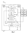
- FIGURE 1 illustrates a portable solar power generator and water heating system 100.
- the portable solar power generator and water heating system 100 is a portable system that may provide power and heated water for consumption.
- the concepts described herein allow for the rapid deployment of a portable solar power generator and water heating system 100 at a remote location.
- the solar power generator and water heating system 100 may be of a size and weight that is capable of being transported by several individuals. The entire system fits easily on a conventional pallet that can be carried to the optimal location and deployed. Deployment of the system may include unrolling a photovoltaic (PV) bladder 102, which will be described in detail below, and connecting inlet and outlet water connections, as well as any supplemental power that may be used if the power generated by the system is not used to entirely power the system.
- PV photovoltaic
- the solar power generator and water heating system 100 includes the PV bladder 102.
- the PV bladder 102 absorbs solar radiation, for example, infrared and visible light, and uses the absorbed radiation to heat a fluid within the bladder as well as to generate electrical power.
- the heated fluid within the bladder, or heat transfer fluid 109 as it is referred to herein, is then used to heat stored water for consumption at the remote location or location of use.
- the PV bladder 102 includes two primary components, a heat transmission bladder 103 and a PV collector backing 105.
- the heat transmission bladder 103 is a flexible container through which heat transfer fluid 109 may be routed to collect heat from the absorbed solar radiation.
- the heat transmission bladder may be created from any suitable material that can be rolled or folded and that is transparent or translucent to allow for the transmission of visible light.
- the heat transmission bladder 103 may include one or more channels for routing a heat transfer fluid 109 into and through the heat transmission bladder 103.
- the heat transmission bladder 103 may be made of a fluoride polymer, for example, ethylene tetrafluroethylene (ETFE).
- ETFE ethylene tetrafluroethylene
- the fluoride polymer used to create the heat transmission bladder 103 may be a fluoride polymer that tends to transmit greater than 50% of the visible spectrum of light through the fluoride polymer. Since the heat transmission bladder 103 resides on top of the PV backing 105 of the PV bladder 102 and is transparent or translucent, the PV bladder 102 can utilize infrared radiation for heating the heat transfer fluid and visible light for power generation.
- the heat transmission bladder 103 and the PV backing 105 of the PV bladder 102 may be attached or integrated in any suitable manner that allows sunlight to be received by both the heat transmission bladder 103 and the PV backing 105.
- the heat transmission bladder 103 absorbs infrared radiation through the heat transfer fluid 109 contained in the heat transmission bladder 103.
- the heat transfer fluid 109 in the heat transmission bladder 103 may be any fluid capable of being heated by solar radiation, for example, water.
- the heat transmission bladder 103 circulates the heat transfer fluid 109 through a heat exchanger 104 using preferably a pump 114 that may be controlled by a system control block 107.
- the heat exchanger 104 transfers heat received from the heat transfer fluid 109 to use water 110 in order to heat the use water 110 for subsequent consumption.
- Pump 114 may be used to provide water pressure to heated use water 110 for extraction and use.
- the pump 114 may also be used to transfer ambient water to the use water 110 for subsequent heating and be used to transfer heated water for use via a heated water outlet.
- the PV backing 105 of the PV bladder 102 may be made from a variety of durable and flexible materials configured with photovoltaic cells for the creation of electrical power from the collected solar radiation.
- Example materials include but are not limited to, copper indium gallium selenide (CIGS), copper indium selenide (CIS), tandum junction amorphous silicon (a-Si), cadmium telluride (CdTe), organic photovoltaics or any other suitable thin film photovoltaic.
- the PV collector backing 105 is dark for optimal absorption of solar radiation through the transparent or translucent heat transmission bladder 103 to which it is attached.
- the PV backing 105 is capable of collecting visible light due to the transparent or translucent nature of the heat transmission bladder 103.
- the PV backing 105 transfers created power to a battery 106 for storage via the system control block 107 that controls power exchanged between components within the solar power generator and water heating system 100.
- the battery 106 may be a 24-volt direct current (DC) battery and may include an outlet for consuming the stored power.
- the solar power generator and water heating system 100 may also include a PV panel 108.
- the PV panel 108 may be made from materials similar to that of the PV backing 105.
- the PV panel 108 may also convert visible light to power for consumption by the solar power generator and water heating system 100 or general use. Power generated from the PV backing 105 and/or the PV panel 108 may be used to power one or more heating elements 112.
- the heating elements 112 may be used to generate heat in order to heat the use water 110. In one embodiment, the heating elements 112 may be direct current (DC) heating elements.
- DC direct current
- the system control block 107 may control the power exchanged between various components of the solar power generator and water heating system 100.
- the system control block 107 may control the power extracted from the PV backing 105 of the PV bladder 102 and stored in the battery 106.
- the system control block 107 may control the power extracted from the PV panel 108 and transferred to the battery 106.
- the system control block 107 may control the transfer of power from the battery 106 to the heating elements 112 and/or to the pump 114.
- the system control block 107 may also be used to regulate and/or monitor such power transfers/exchanges.
- the control system block 107 may include a central processing unit and a memory along with other components to control power transfer/exchanges.
- the solar power generator and water heating system 100 may use a container 120 to house the pump 114, use water 110, heat exchanger 104, battery 106, heating elements 112, system control block 107, and PV panel 108.
- the container 120 may also be used to stow the PV bladder 102.
- the container 120 may be a conventional pallet of any size commonly used for the transport and storage of equipment and goods.
- the container 120 may also be specifically configured or customized for hand carrying, pushing, or pulling by multiple individuals, including handles and/or wheels or skids.
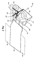
- FIGURE 2 illustrates an embodiment of a solar power generator and water heating system 200.
- the portable solar power generator and water heating system 200 includes a PV bladder 202.
- the PV bladder 202 may be used to absorb infrared radiation to generate heat via a heat transmission bladder (not shown) and absorb visible light to generate power via a PV backing (not shown).
- the dimension of the PV bladder 202 may vary depending on the amount of heat transfer fluid desired to be circulated through the PV bladder 202.
- the PV bladder 202 may have a dimension of 4.9 m by 2.3 m (16 feet by 7.58 feet).
- the PV bladder 202 may absorb solar radiation once the PV bladder 202 is un-rolled in a sunny location.
- Any heat collected through the absorption of solar radiation by the PV bladder 202 may be transferred to water storage tanks 210 and 212 by circulating the heat transfer fluid in the PV bladder 202 through a heat exchanger 206 that may be in thermal contact with the water storage tanks 210 and 212.
- the portable solar power generator and water heating system 200 may use one or more water pumps 208 to circulate the heat transfer fluid through the heat exchanger 206 via heated fluid transfer conduit 230.
- the portable solar power generator and water heating system 200 may also use the one or more water pumps 208 to circulate exchanged heat transfer fluid from the heat exchanger 206 back to the PV bladder 202 via ambient fluid transfer conduit 232.
- the heat exchanger 206 may be a flat plate heat exchanger or any other suitable instrument for exchanging heat.
- the water storage tanks 210 and 212 may be filled with water via an ambient water inlet (not shown).
- the water storage tanks 210 and 212 may be interconnected and water may be exchanged between the water storage tanks 210 and 212.
- the water storage tanks 210 and 212 may be the same size or, alternatively, may vary in size.
- water storage tank 210 may be smaller in comparison to water storage tank 212.
- the water storage tank 210 may be used to provide heated water for use more rapidly than the water storage tank 212 due to the volume of water being heated in both tanks. Accordingly, the water storage tank 210 may provide some amount of heated water, for example, 22.7 l (six gallons), for consumption in a shorter period, for example, five hours, while the larger water storage tank 212 is being heated.
- One or more heating elements may be used with the water storage tank 210 to further reduce the water heating time.
- the one or more water pumps 208 may also be used to provide water pressure to extract the heated water from the water storage tank 210 and/or water storage tank 212 at a heated water outlet 218 that is connected to water storage tank 210 (not shown) and/or water storage tank 212.
- Any power generated through the absorption of visible light by the PV bladder 202 may be transferred to a direct current (DC) power unit 222 via a power control block (not shown) and a power conduit 236.
- the DC power unit 222 may include power control logic and one or more power outlets.
- the power generated through the absorption of visible light by the PV bladder 202 may also be used for general consumption by and/or operating the solar power generator and water heating system 200 via the power control block.
- the portable solar power generator and water heating system 200 may also include one or more foldout PV collectors 204.
- the foldout PV collectors 204 may be made of a material similar to the material used to create the PV backing of the PV bladder 202. In one embodiment, each of the PV collectors 204 may be 2 m by 4 m (6.5 feet by 13 feet), thereby providing an additional collection area of about 15.8 m 2 (170 square feet).
- the foldout PV collectors 204 may collect visible light that is converted, together with the visible light collected by the PV bladder 202, to power which may be used to charge DC power unit 222 via the power control block and power conduit 236.
- the portable solar power generator and water heating system 200 may also include a rigid PV panel 220.
- the PV panel 220 may vary in size.
- the PV panel 220 may have the dimensions of 1.8 m by 1.5m (6.4 feet by 5.4 feet), thereby providing an additional collection area of about 3.3 m 2 (35 square feet).
- the PV panel 220 may be rotatable in order to tilt the PV panel 220 in a direction of incoming sunlight.
- the PV panel 220 may be positioned to shade the various components of the portable solar power generator and water heating system 200 during daylight hours and provide insulation for the water storage tanks 210 and 212 during the night. Converted power created by the PV panel 220 may also charge the DC power unit 222 via the power control block.
- the power generated by the PV backing of the PV bladder 202, the one or more foldout PV collectors 204, and the PV panel 220 may also be used to operate the one or more pumps 208, transfer water between water storage tanks 210 and 212, and operate one or more heating elements 112 (not shown).
- the PV backing of the PV bladder 202, the foldout PV collectors 204, and PV panel 220 may convert approximately nine kilowatt-hours of energy within a 24-hour period in a given location.
- This energy could be used to operate the one or more water pumps 208, which may use four or more kilowatt-hours of energy to operate within a 24-hour period in a given location.
- a portion of the nine kilowatt-hours of collected energy may also be used to operate heating elements that may be attached to the water storage tanks 210 and 212, which may use three or more kilowatt-hours of energy to operate.
- a portion of the nine kilowatt-hours of energy may be used to operate various valves and controls of the portable solar power generator and water heating system 200.
- the remaining energy from the nine kilowatt-hours of collected energy may be stored in the DC power unit 222.
- the portable solar power generator and water heating system 200 may heat water to a given temperature for consumption, for example, 189 l at 38 °C (fifty gallons at 100 degrees Fahrenheit (F)).
- the portable solar power generator and water heating system 200 may utilize a second PV bladder 202 and a second set of foldout PV collectors 204, illustrated in a stowed configuration 250, to also provide heated water and power for use.
- a second PV bladder 202 and a second set of foldout PV collectors 204 illustrated in a stowed configuration 250, to also provide heated water and power for use.
- both sets of PV bladders 202 and foldout PV collectors 204 are in a stowed configuration 250, the overall size of the portable solar power generator and water heating system 200 is reduced easing the logistics for transporting the portable solar power generator and water heating system 200.
- the portable solar power generator and water heating system 200 may be housed on a container 240 for transport.
- the portable solar power generator and water heating system 200 may be used without filling the PV bladder 202 with the heat transfer fluid. In this configuration, the portable solar power generator and water heating system 200 may provide heated water using the heating elements 112 (shown in FIGURE 1 ) as well as power. In another embodiment, the solar power generator and water heating system 200 does not supply heated water but, rather, solely provides power. As such, this design also does not require the heating elements 112 to be operational.
- FIGURE 3 illustrates a portable solar power generator system 300 not according to the present invention for solely providing power.
- the portable solar power generator 300 may include one or more foldout PV collectors 204.
- the foldout PV collectors 204 may be wide enough to create wings in relation to a PV collector 302.
- the PV collector 302 may be made from the same material in which the foldout PV collectors 204 are made.
- the PV collector 302 may vary in size.
- the PV collector 302 may have dimensions of 20 m by 2.3 m (66 feet by 7.58 feet).
- the foldout PV collectors 204 and PV collector 302 may collect visible light and convert the received visible light to power that may be used to charge DC power unit 222 and battery 304 using the power control block (not shown) and power conduit 236 and operate various components of the portable solar power generator system 300 using the power control block.
- the battery 304 may be a 24-volt direct current (DC) battery and include one or more batteries and inverters.
- the portable solar power generator system 300 may also include the PV panel 220. Converted power created by the PV panel 220 may also charge DC power unit 222 and the battery 304 using the power control block.
- the power generated by the foldout PV collectors 204, the PV collector 302 and the PV panel 220 may be used for general consumption and to power various components of the portable solar power generator system 300 using the power control block.
- the foldout PV collector 204, the PV collector 302 and the PV panel 220 may convert approximately fifty kilowatt-hours of energy within a 24-hour period for storage in the battery 304.
- the portable solar power generator system 300 may utilize a second PV collector 302 and a second set of foldout PV collectors 204, illustrated in a stowed configuration 350, to provide power for use.
- a second PV collector 302 and a second set of foldout PV collectors 204 illustrated in a stowed configuration 350
- the overall size of the portable solar power generator system 300 is reduced easing the logistics for transporting the portable solar power generator system 300.
- the portable solar power generator system 300 may be housed on a container 240 for transport.
- FIGURE 4 is a flow diagram showing a routine 400 of one illustrative process disclosed herein for generating power and providing heated water from solar radiation.
- the process references the solar power generator and water heating system 100, 200 of FIGURES 1 and 2 , respectively. It should also be appreciated that more or fewer operations may be performed than shown in the figures and described herein. These operations may also be performed in a different order than those described herein.
- the routine 400 begins at operation 402, where the PV bladder 202 and the one or more foldout PV collectors 204 are deployed.
- the PV bladder 202, the one or more foldout PV collectors 204 and the PV panel 220 receive solar radiation, for example, infrared radiation and visible light, via the heat transfer fluid and the PV material used by the PV bladder 202, the one or more foldout PV collectors 204 and the PV panel 220.
- solar radiation absorbed by the PV bladder 202, the PV collectors 204, and the PV panel 220 is converted to power.
- the converted power is provided for use by the components of the portable solar power generator and water heating system 200, for example, to operate the water pumps 208 and the heating elements 112, and a portion of the converted power is stored in the DC power unit 222.
- the converted power is also provided for general consumption via a power outlet.
- the heat transfer fluid is routed through the heat exchanger 206 to transfer heat from the heat transfer fluid to water stored in the water storage tanks 210 and 212.
- the heated water is provided for general consumption. The operation 400 subsequently ends.
- FIGURE 5 is a flow diagram showing a routine 500 that illustrates aspects of one illustrative process disclosed herein for generating power from solar radiation.
- the process references the solar power generator and water heating system 100, 200 of FIGURES 1 and 2 , respectively, and the solar power generator system 300.
- the routine 500 begins at operation 502, where the one or more foldout PV collectors 204 and the PV collector 302 are deployed.
- the foldout PV collectors 204, the PV collector 302, and the PV panel 220 receive solar radiation.
- the solar radiation absorbed by the foldout PV collectors 204, the PV collector 302 and the PV panel 220 is converted to power.
- the converted power is stored in the DC power unit 222 and the battery 304.
- the converted power is also provided for use by components of the portable solar power generator system 300 and for general consumption.
- the operation 500 subsequently ends.
- the portable solar power generator and water heating system 100, the portable solar power generator and water heating system 200 encompassed by the claims below, and the portable solar power generator system 300 described herein provide an improvement in operating efficiency over conventional systems, effectively reducing operating costs, reducing logistical costs associated with transporting fuel, and decreasing the casualty risks corresponding with the hazardous transportation of fuel to forward operating bases.
- the portable solar power generator and water heating system 100, the portable solar power generator and water heating system 200, and the portable solar power generator system 300 utilizes solar radiation to provide heated water and/or provide power at a base, reducing fuel consumption rates of the base as compared to traditional generator sets.
- the portable solar power generator and water heating system 100, the portable solar power generator and water heating system 200, the portable solar power generator system 300 may be modular and components of each system may be exchanged or interchanged.
Landscapes
- Engineering & Computer Science (AREA)
- Life Sciences & Earth Sciences (AREA)
- Sustainable Development (AREA)
- Sustainable Energy (AREA)
- Physics & Mathematics (AREA)
- Thermal Sciences (AREA)
- Chemical & Material Sciences (AREA)
- Combustion & Propulsion (AREA)
- Mechanical Engineering (AREA)
- General Engineering & Computer Science (AREA)
- Photovoltaic Devices (AREA)
- Heat-Pump Type And Storage Water Heaters (AREA)
Claims (15)
- Procédé de chauffage d'eau et de production d'énergie, le procédé comprenant :le déploiement (402, 502) d'une vessie photovoltaïque (PV) (102, 202) depuis une configuration rangée (250, 350), la vessie PV comprenant une vessie de transmission de chaleur (103) et une doublure PV (105), la vessie de transmission de chaleur étant située au-dessus de la doublure PV ;l'acheminement (412) d'un fluide de transfert de chaleur (109) à travers la vessie de transmission de chaleur ;la réception (404, 504) du rayonnement solaire au niveau de la vessie PV ;l'acheminement (412) du fluide de transfert de chaleur de la vessie de transmission de chaleur à un échangeur de chaleur (104, 206) ; etle transfert (412) de chaleur du fluide de transfert de chaleur par l'échangeur de chaleur à de l'eau (110) stockée à l'intérieur d'un ou plusieurs réservoirs de stockage d'eau (210, 212).
- Procédé de la revendication 1, comprenant en outre :la conversion (408, 506) du rayonnement solaire reçu au niveau de la vessie PV (102, 202) en énergie ; etle stockage (508) de l'énergie dans une unité d'alimentation à courant continu (CC) (222).
- Procédé de la revendication 1, dans lequel la vessie de transmission de chaleur (103) est une vessie translucide.
- Procédé de la revendication 2, comprenant en outre la fourniture (510) de l'énergie pour faire fonctionner un ou plusieurs éléments chauffants (112) afin de chauffer l'eau (110) stockée à l'intérieur du ou des réservoirs de stockage d'eau (210, 212).
- Procédé de la revendication 2 ou 4, comprenant en outre la fourniture (510) de l'énergie pour faire fonctionner une ou plusieurs pompes (114) afin de faire circuler le fluide de transfert de chaleur (109) entre la vessie de transmission de chaleur (103) et l'échangeur de chaleur (104, 206).
- Système de production d'énergie solaire et d'eau portatif (100, 200), comprenant :une vessie PV (102, 202) comprenant :une vessie de transmission de chaleur (103) configurée pour absorber le rayonnement solaire au moyen d'un fluide de transfert de chaleur (109) remplissant la vessie de transmission de chaleur ; etune doublure PV (105) configurée pour convertir le rayonnement solaire absorbé à travers la doublure PV en énergie, la vessie de transmission de chaleur étant située au-dessus de la doublure PV ;un échangeur de chaleur (104, 206) servant à transférer la chaleur du fluide de transfert de chaleur à de l'eau (110) stockée dans un ou plusieurs réservoirs de stockage d'eau (210, 212) ; etune unité d'alimentation CC (222) servant à stocker l'énergie convertie par la vessie PV.
- Système de production d'énergie et d'eau (100, 200) de la revendication 6, comprenant en outre une ou plusieurs pompes (114, 208) pour faire circuler le fluide de transfert de chaleur (109) entre la vessie de transmission de chaleur (103) et l'échangeur de chaleur (104, 206).
- Système de production d'énergie et d'eau (100, 200) de la revendication 7, dans lequel la ou les pompes (114, 208) fournissent de la pression pour extraire l'eau chauffée (110) du ou des réservoirs de stockage d'eau (210, 212).
- Système de production d'énergie et d'eau (100, 200) de l'une quelconque des revendications 6 à 8, dans lequel la vessie de transmission de chaleur est composée d'un polymère de fluorure.
- Système de production d'énergie et d'eau (100, 200) de la revendication 9, dans lequel le polymère de fluorure est l'éthylène-tétrafluoroéthylène.
- Système de production d'énergie et d'eau (100, 200) de la revendication 9 et 10, dans lequel le polymère de fluorure transmet plus de 50 % du spectre visible à travers le polymère de fluorure.
- Système de production d'énergie et d'eau (100, 200) de l'une quelconque des revendications 6 à 11, dans lequel la doublure PV (105) est composée d'un matériau photovoltaïque en couche mince.
- Système de production d'énergie et d'eau (100, 200) de la revendication 12, dans lequel le matériau photovoltaïque en couche mince est un matériau en séléniure de cuivre-indium-gallium, et/ou un matériau en silicium amorphe à jonction tandem, et/ou un matériau en tellurure de cadmium.
- Système de production d'énergie et d'eau (100, 200) de l'une quelconque des revendications 6 à 13, comprenant en outre un ou plusieurs collecteurs PV dépliés (204) pour convertir le rayonnement solaire en énergie.
- Système de production d'énergie et d'eau (100, 200) de l'une quelconque des revendications 6 à 14, comprenant en outre un panneau PV rigide (220) pour convertir le rayonnement solaire en énergie.
Applications Claiming Priority (2)
| Application Number | Priority Date | Filing Date | Title |
|---|---|---|---|
| US12/969,322 US20120152319A1 (en) | 2010-12-15 | 2010-12-15 | Portable Solar Power Generator and Water Heating System |
| PCT/US2011/052833 WO2012082206A2 (fr) | 2010-12-15 | 2011-09-22 | Générateur d'énergie solaire portatif et système de chauffage d'eau |
Publications (2)
| Publication Number | Publication Date |
|---|---|
| EP2652414A2 EP2652414A2 (fr) | 2013-10-23 |
| EP2652414B1 true EP2652414B1 (fr) | 2015-11-18 |
Family
ID=44789596
Family Applications (1)
| Application Number | Title | Priority Date | Filing Date |
|---|---|---|---|
| EP11768205.4A Active EP2652414B1 (fr) | 2010-12-15 | 2011-09-22 | Générateur d'énergie solaire portatif et système de chauffage d'eau |
Country Status (5)
| Country | Link |
|---|---|
| US (1) | US20120152319A1 (fr) |
| EP (1) | EP2652414B1 (fr) |
| CN (1) | CN103261809A (fr) |
| AU (1) | AU2011341720B2 (fr) |
| WO (1) | WO2012082206A2 (fr) |
Families Citing this family (6)
| Publication number | Priority date | Publication date | Assignee | Title |
|---|---|---|---|---|
| CA2798200A1 (fr) * | 2011-12-07 | 2013-06-07 | Alessandro Seccareccia | Couvre-piscine dote d'un chauffage |
| US9267710B2 (en) | 2012-04-18 | 2016-02-23 | Solight Solar, Inc. | Solar thermal collectors and thin plate heat exchangers for solar applications |
| US9528235B1 (en) * | 2012-10-01 | 2016-12-27 | Desmond Irving | Solar powered ice/snow melting system and associated use thereof |
| ITUA20163321A1 (it) * | 2016-05-10 | 2017-11-10 | Francesco Giglio | Dispositivo solare termico innovativo ed ecosostenibile per la produzione di acqua calda |
| US10447200B1 (en) * | 2017-11-20 | 2019-10-15 | Ali A. Fakih | Solar photovoltiac cell system |
| CN111189239A (zh) * | 2019-12-27 | 2020-05-22 | 柳梧新区库阳环保科技有限责任公司 | 便携式太阳能蓄热装置 |
Family Cites Families (19)
| Publication number | Priority date | Publication date | Assignee | Title |
|---|---|---|---|---|
| US5293447A (en) * | 1992-06-02 | 1994-03-08 | The United States Of America As Represented By The Secretary Of Commerce | Photovoltaic solar water heating system |
| ES2120290B1 (es) * | 1994-02-07 | 1999-05-01 | Barreto Avero Manuel | Colector compacto para energia solar. |
| WO1996008683A1 (fr) * | 1994-09-15 | 1996-03-21 | Colin Francis Johnson | Concentrateur d'energie solaire destine a la production de chaleur et d'electricite |
| JP2000269535A (ja) * | 1999-01-14 | 2000-09-29 | Canon Inc | 太陽電池モジュール、発電装置、太陽電池モジュールの分離方法及び太陽電池モジュールの再生方法 |
| US6295818B1 (en) * | 1999-06-29 | 2001-10-02 | Powerlight Corporation | PV-thermal solar power assembly |
| US6675580B2 (en) * | 1999-06-29 | 2004-01-13 | Powerlight Corporation | PV/thermal solar power assembly |
| US20050268962A1 (en) * | 2000-04-27 | 2005-12-08 | Russell Gaudiana | Flexible Photovoltaic cells, systems and methods |
| US20080017499A1 (en) * | 2004-07-06 | 2008-01-24 | Brockhoff Bruce W | Solar Collector |
| US7340899B1 (en) * | 2004-10-26 | 2008-03-11 | Solar Energy Production Corporation | Solar power generation system |
| CN100575811C (zh) * | 2006-04-11 | 2009-12-30 | 涂济民 | 太阳能光伏发电-热水器复合组件及系统 |
| CN2932220Y (zh) * | 2006-06-08 | 2007-08-08 | 许志龙 | 太阳能光电热水器 |
| CN1862148A (zh) * | 2006-06-16 | 2006-11-15 | 东南大学 | 太阳能热泵制热与光伏发电一体化装置 |
| CN1869540A (zh) * | 2006-06-27 | 2006-11-29 | 戴文育 | 太阳热能热能利用装置 |
| JP2008151490A (ja) * | 2006-12-20 | 2008-07-03 | Electric Power Dev Co Ltd | 太陽光発電集熱ユニット |
| US20080202498A1 (en) * | 2007-02-28 | 2008-08-28 | Victor Manuel Ramos | Self-sufficient portable heating system using renewable energy |
| CN201038175Y (zh) * | 2007-04-27 | 2008-03-19 | 昆山太得隆机械有限公司 | 平板式太阳能发电制热器 |
| US20090159118A1 (en) * | 2007-12-19 | 2009-06-25 | Kalkanoglu Husnu M | Roofing Products Having Receptor Zones and Photovoltaic Roofing Elements and Systems Using Them |
| US9702586B2 (en) * | 2008-02-25 | 2017-07-11 | Samuel L. Thomasson | Energy storage for PV water heater |
| GB0814007D0 (en) * | 2008-07-31 | 2008-09-10 | Flynn James P | Solar water heating panel |
-
2010
- 2010-12-15 US US12/969,322 patent/US20120152319A1/en not_active Abandoned
-
2011
- 2011-09-22 EP EP11768205.4A patent/EP2652414B1/fr active Active
- 2011-09-22 WO PCT/US2011/052833 patent/WO2012082206A2/fr not_active Ceased
- 2011-09-22 AU AU2011341720A patent/AU2011341720B2/en active Active
- 2011-09-22 CN CN2011800604190A patent/CN103261809A/zh active Pending
Also Published As
| Publication number | Publication date |
|---|---|
| WO2012082206A3 (fr) | 2013-06-20 |
| WO2012082206A2 (fr) | 2012-06-21 |
| EP2652414A2 (fr) | 2013-10-23 |
| CN103261809A (zh) | 2013-08-21 |
| AU2011341720A1 (en) | 2013-04-04 |
| US20120152319A1 (en) | 2012-06-21 |
| AU2011341720B2 (en) | 2014-10-23 |
Similar Documents
| Publication | Publication Date | Title |
|---|---|---|
| EP2652414B1 (fr) | Générateur d'énergie solaire portatif et système de chauffage d'eau | |
| US11619423B2 (en) | All-in-one integrated multifunctional triple power module | |
| Colozza et al. | Initial feasibility assessment of a high altitude long endurance airship | |
| US9711705B2 (en) | Systems, methods and/or apparatus for thermoelectric energy generation | |
| US7469541B1 (en) | Portable power system | |
| EP3871286B1 (fr) | Procédés et appareil de gestion d'énergie thermique dans des véhicules électriques | |
| EP3316478B1 (fr) | Module de puissance triple multifonctionnel intégré "itm" tout-en-un | |
| US20050231157A1 (en) | Personal renewable-energy fueling & storage station for electric-powered vehicles | |
| GB2512418A (en) | Mobile power system | |
| CN104170107A (zh) | 用于热电能生成的系统、方法和/或设备 | |
| US20120097211A1 (en) | Electric power generators and systems comprising same | |
| US20180175629A1 (en) | Mobile Disaster Survival System | |
| CN212716986U (zh) | 利用太阳能风能模块化节能建筑综合体及雨水自循环系统 | |
| JP2010258031A (ja) | 発電システム | |
| CN108923725A (zh) | 一种基于薄膜太阳能电池的风电机组塔筒供电系统 | |
| CN118855654A (zh) | 一种地外人居环境空间发电蓄能热循环一体化维持系统 | |
| US11767825B2 (en) | Power generating system utilizing expanding fluid | |
| Freeh | Analysis of stationary, photovoltaic-based surface power system designs at the lunar south pole | |
| Miller et al. | Spacecraft power systems | |
| Teren | Space station electric power system requirements and design | |
| WO2012083377A1 (fr) | Appareil d'énergie thermique solaire | |
| Adnan et al. | Modular & COTS based power system for small LEO satellite | |
| US20260066834A1 (en) | Synergistic tracking integrated photovoltaic and concentrating cogeneration solar energy harvesting system | |
| Graham | Solar Energy: Let the Sun Shine In | |
| Sanz Verdesoto | Evaluation of Solar Thermal and Photovoltaic Energy Conversion Technologies for Sustainab Development |
Legal Events
| Date | Code | Title | Description |
|---|---|---|---|
| PUAI | Public reference made under article 153(3) epc to a published international application that has entered the european phase |
Free format text: ORIGINAL CODE: 0009012 |
|
| 17P | Request for examination filed |
Effective date: 20130711 |
|
| AK | Designated contracting states |
Kind code of ref document: A2 Designated state(s): AL AT BE BG CH CY CZ DE DK EE ES FI FR GB GR HR HU IE IS IT LI LT LU LV MC MK MT NL NO PL PT RO RS SE SI SK SM TR |
|
| DAX | Request for extension of the european patent (deleted) | ||
| 17Q | First examination report despatched |
Effective date: 20140812 |
|
| REG | Reference to a national code |
Ref country code: DE Ref legal event code: R079 Ref document number: 602011021451 Country of ref document: DE Free format text: PREVIOUS MAIN CLASS: F24H0001060000 Ipc: F24D0017000000 |
|
| RIC1 | Information provided on ipc code assigned before grant |
Ipc: F24J 2/04 20060101ALI20150325BHEP Ipc: H02S 40/44 20140101ALI20150325BHEP Ipc: F24J 2/36 20060101ALI20150325BHEP Ipc: F24D 17/00 20060101AFI20150325BHEP |
|
| GRAP | Despatch of communication of intention to grant a patent |
Free format text: ORIGINAL CODE: EPIDOSNIGR1 |
|
| INTG | Intention to grant announced |
Effective date: 20150519 |
|
| GRAS | Grant fee paid |
Free format text: ORIGINAL CODE: EPIDOSNIGR3 |
|
| GRAA | (expected) grant |
Free format text: ORIGINAL CODE: 0009210 |
|
| AK | Designated contracting states |
Kind code of ref document: B1 Designated state(s): AL AT BE BG CH CY CZ DE DK EE ES FI FR GB GR HR HU IE IS IT LI LT LU LV MC MK MT NL NO PL PT RO RS SE SI SK SM TR |
|
| REG | Reference to a national code |
Ref country code: GB Ref legal event code: FG4D |
|
| REG | Reference to a national code |
Ref country code: CH Ref legal event code: EP |
|
| REG | Reference to a national code |
Ref country code: AT Ref legal event code: REF Ref document number: 761768 Country of ref document: AT Kind code of ref document: T Effective date: 20151215 |
|
| REG | Reference to a national code |
Ref country code: IE Ref legal event code: FG4D |
|
| REG | Reference to a national code |
Ref country code: DE Ref legal event code: R096 Ref document number: 602011021451 Country of ref document: DE |
|
| REG | Reference to a national code |
Ref country code: NL Ref legal event code: MP Effective date: 20160218 |
|
| REG | Reference to a national code |
Ref country code: LT Ref legal event code: MG4D |
|
| REG | Reference to a national code |
Ref country code: AT Ref legal event code: MK05 Ref document number: 761768 Country of ref document: AT Kind code of ref document: T Effective date: 20151118 |
|
| PG25 | Lapsed in a contracting state [announced via postgrant information from national office to epo] |
Ref country code: NO Free format text: LAPSE BECAUSE OF FAILURE TO SUBMIT A TRANSLATION OF THE DESCRIPTION OR TO PAY THE FEE WITHIN THE PRESCRIBED TIME-LIMIT Effective date: 20160218 Ref country code: IT Free format text: LAPSE BECAUSE OF FAILURE TO SUBMIT A TRANSLATION OF THE DESCRIPTION OR TO PAY THE FEE WITHIN THE PRESCRIBED TIME-LIMIT Effective date: 20151118 Ref country code: IS Free format text: LAPSE BECAUSE OF FAILURE TO SUBMIT A TRANSLATION OF THE DESCRIPTION OR TO PAY THE FEE WITHIN THE PRESCRIBED TIME-LIMIT Effective date: 20160318 Ref country code: ES Free format text: LAPSE BECAUSE OF FAILURE TO SUBMIT A TRANSLATION OF THE DESCRIPTION OR TO PAY THE FEE WITHIN THE PRESCRIBED TIME-LIMIT Effective date: 20151118 Ref country code: NL Free format text: LAPSE BECAUSE OF FAILURE TO SUBMIT A TRANSLATION OF THE DESCRIPTION OR TO PAY THE FEE WITHIN THE PRESCRIBED TIME-LIMIT Effective date: 20151118 Ref country code: LT Free format text: LAPSE BECAUSE OF FAILURE TO SUBMIT A TRANSLATION OF THE DESCRIPTION OR TO PAY THE FEE WITHIN THE PRESCRIBED TIME-LIMIT Effective date: 20151118 Ref country code: HR Free format text: LAPSE BECAUSE OF FAILURE TO SUBMIT A TRANSLATION OF THE DESCRIPTION OR TO PAY THE FEE WITHIN THE PRESCRIBED TIME-LIMIT Effective date: 20151118 |
|
| PG25 | Lapsed in a contracting state [announced via postgrant information from national office to epo] |
Ref country code: FI Free format text: LAPSE BECAUSE OF FAILURE TO SUBMIT A TRANSLATION OF THE DESCRIPTION OR TO PAY THE FEE WITHIN THE PRESCRIBED TIME-LIMIT Effective date: 20151118 Ref country code: PL Free format text: LAPSE BECAUSE OF FAILURE TO SUBMIT A TRANSLATION OF THE DESCRIPTION OR TO PAY THE FEE WITHIN THE PRESCRIBED TIME-LIMIT Effective date: 20151118 Ref country code: PT Free format text: LAPSE BECAUSE OF FAILURE TO SUBMIT A TRANSLATION OF THE DESCRIPTION OR TO PAY THE FEE WITHIN THE PRESCRIBED TIME-LIMIT Effective date: 20160318 Ref country code: GR Free format text: LAPSE BECAUSE OF FAILURE TO SUBMIT A TRANSLATION OF THE DESCRIPTION OR TO PAY THE FEE WITHIN THE PRESCRIBED TIME-LIMIT Effective date: 20160219 Ref country code: AT Free format text: LAPSE BECAUSE OF FAILURE TO SUBMIT A TRANSLATION OF THE DESCRIPTION OR TO PAY THE FEE WITHIN THE PRESCRIBED TIME-LIMIT Effective date: 20151118 Ref country code: SE Free format text: LAPSE BECAUSE OF FAILURE TO SUBMIT A TRANSLATION OF THE DESCRIPTION OR TO PAY THE FEE WITHIN THE PRESCRIBED TIME-LIMIT Effective date: 20151118 Ref country code: RS Free format text: LAPSE BECAUSE OF FAILURE TO SUBMIT A TRANSLATION OF THE DESCRIPTION OR TO PAY THE FEE WITHIN THE PRESCRIBED TIME-LIMIT Effective date: 20151118 Ref country code: LV Free format text: LAPSE BECAUSE OF FAILURE TO SUBMIT A TRANSLATION OF THE DESCRIPTION OR TO PAY THE FEE WITHIN THE PRESCRIBED TIME-LIMIT Effective date: 20151118 |
|
| PG25 | Lapsed in a contracting state [announced via postgrant information from national office to epo] |
Ref country code: CZ Free format text: LAPSE BECAUSE OF FAILURE TO SUBMIT A TRANSLATION OF THE DESCRIPTION OR TO PAY THE FEE WITHIN THE PRESCRIBED TIME-LIMIT Effective date: 20151118 |
|
| REG | Reference to a national code |
Ref country code: DE Ref legal event code: R097 Ref document number: 602011021451 Country of ref document: DE |
|
| PG25 | Lapsed in a contracting state [announced via postgrant information from national office to epo] |
Ref country code: SM Free format text: LAPSE BECAUSE OF FAILURE TO SUBMIT A TRANSLATION OF THE DESCRIPTION OR TO PAY THE FEE WITHIN THE PRESCRIBED TIME-LIMIT Effective date: 20151118 Ref country code: EE Free format text: LAPSE BECAUSE OF FAILURE TO SUBMIT A TRANSLATION OF THE DESCRIPTION OR TO PAY THE FEE WITHIN THE PRESCRIBED TIME-LIMIT Effective date: 20151118 Ref country code: SK Free format text: LAPSE BECAUSE OF FAILURE TO SUBMIT A TRANSLATION OF THE DESCRIPTION OR TO PAY THE FEE WITHIN THE PRESCRIBED TIME-LIMIT Effective date: 20151118 Ref country code: DK Free format text: LAPSE BECAUSE OF FAILURE TO SUBMIT A TRANSLATION OF THE DESCRIPTION OR TO PAY THE FEE WITHIN THE PRESCRIBED TIME-LIMIT Effective date: 20151118 Ref country code: RO Free format text: LAPSE BECAUSE OF FAILURE TO SUBMIT A TRANSLATION OF THE DESCRIPTION OR TO PAY THE FEE WITHIN THE PRESCRIBED TIME-LIMIT Effective date: 20151118 |
|
| PLBE | No opposition filed within time limit |
Free format text: ORIGINAL CODE: 0009261 |
|
| STAA | Information on the status of an ep patent application or granted ep patent |
Free format text: STATUS: NO OPPOSITION FILED WITHIN TIME LIMIT |
|
| REG | Reference to a national code |
Ref country code: FR Ref legal event code: PLFP Year of fee payment: 6 |
|
| 26N | No opposition filed |
Effective date: 20160819 |
|
| PG25 | Lapsed in a contracting state [announced via postgrant information from national office to epo] |
Ref country code: SI Free format text: LAPSE BECAUSE OF FAILURE TO SUBMIT A TRANSLATION OF THE DESCRIPTION OR TO PAY THE FEE WITHIN THE PRESCRIBED TIME-LIMIT Effective date: 20151118 |
|
| PG25 | Lapsed in a contracting state [announced via postgrant information from national office to epo] |
Ref country code: BE Free format text: LAPSE BECAUSE OF FAILURE TO SUBMIT A TRANSLATION OF THE DESCRIPTION OR TO PAY THE FEE WITHIN THE PRESCRIBED TIME-LIMIT Effective date: 20151118 |
|
| PG25 | Lapsed in a contracting state [announced via postgrant information from national office to epo] |
Ref country code: MC Free format text: LAPSE BECAUSE OF FAILURE TO SUBMIT A TRANSLATION OF THE DESCRIPTION OR TO PAY THE FEE WITHIN THE PRESCRIBED TIME-LIMIT Effective date: 20151118 |
|
| REG | Reference to a national code |
Ref country code: CH Ref legal event code: PL |
|
| REG | Reference to a national code |
Ref country code: IE Ref legal event code: MM4A |
|
| PG25 | Lapsed in a contracting state [announced via postgrant information from national office to epo] |
Ref country code: CH Free format text: LAPSE BECAUSE OF NON-PAYMENT OF DUE FEES Effective date: 20160930 Ref country code: IE Free format text: LAPSE BECAUSE OF NON-PAYMENT OF DUE FEES Effective date: 20160922 Ref country code: LI Free format text: LAPSE BECAUSE OF NON-PAYMENT OF DUE FEES Effective date: 20160930 |
|
| PG25 | Lapsed in a contracting state [announced via postgrant information from national office to epo] |
Ref country code: LU Free format text: LAPSE BECAUSE OF NON-PAYMENT OF DUE FEES Effective date: 20160922 |
|
| REG | Reference to a national code |
Ref country code: FR Ref legal event code: PLFP Year of fee payment: 7 |
|
| PG25 | Lapsed in a contracting state [announced via postgrant information from national office to epo] |
Ref country code: HU Free format text: LAPSE BECAUSE OF FAILURE TO SUBMIT A TRANSLATION OF THE DESCRIPTION OR TO PAY THE FEE WITHIN THE PRESCRIBED TIME-LIMIT; INVALID AB INITIO Effective date: 20110922 Ref country code: CY Free format text: LAPSE BECAUSE OF FAILURE TO SUBMIT A TRANSLATION OF THE DESCRIPTION OR TO PAY THE FEE WITHIN THE PRESCRIBED TIME-LIMIT Effective date: 20151118 |
|
| PG25 | Lapsed in a contracting state [announced via postgrant information from national office to epo] |
Ref country code: MT Free format text: LAPSE BECAUSE OF NON-PAYMENT OF DUE FEES Effective date: 20160930 Ref country code: TR Free format text: LAPSE BECAUSE OF FAILURE TO SUBMIT A TRANSLATION OF THE DESCRIPTION OR TO PAY THE FEE WITHIN THE PRESCRIBED TIME-LIMIT Effective date: 20151118 Ref country code: MK Free format text: LAPSE BECAUSE OF FAILURE TO SUBMIT A TRANSLATION OF THE DESCRIPTION OR TO PAY THE FEE WITHIN THE PRESCRIBED TIME-LIMIT Effective date: 20151118 |
|
| PG25 | Lapsed in a contracting state [announced via postgrant information from national office to epo] |
Ref country code: BG Free format text: LAPSE BECAUSE OF FAILURE TO SUBMIT A TRANSLATION OF THE DESCRIPTION OR TO PAY THE FEE WITHIN THE PRESCRIBED TIME-LIMIT Effective date: 20151118 |
|
| REG | Reference to a national code |
Ref country code: FR Ref legal event code: PLFP Year of fee payment: 8 |
|
| PG25 | Lapsed in a contracting state [announced via postgrant information from national office to epo] |
Ref country code: AL Free format text: LAPSE BECAUSE OF FAILURE TO SUBMIT A TRANSLATION OF THE DESCRIPTION OR TO PAY THE FEE WITHIN THE PRESCRIBED TIME-LIMIT Effective date: 20151118 |
|
| P01 | Opt-out of the competence of the unified patent court (upc) registered |
Effective date: 20230516 |
|
| PGFP | Annual fee paid to national office [announced via postgrant information from national office to epo] |
Ref country code: DE Payment date: 20250929 Year of fee payment: 15 |
|
| PGFP | Annual fee paid to national office [announced via postgrant information from national office to epo] |
Ref country code: GB Payment date: 20250929 Year of fee payment: 15 |
|
| PGFP | Annual fee paid to national office [announced via postgrant information from national office to epo] |
Ref country code: FR Payment date: 20250925 Year of fee payment: 15 |