EP2653045A1 - Article à fumer comprenant un filtre avec élément de restriction de débit et ventilation en amont - Google Patents
Article à fumer comprenant un filtre avec élément de restriction de débit et ventilation en amont Download PDFInfo
- Publication number
- EP2653045A1 EP2653045A1 EP12164931.3A EP12164931A EP2653045A1 EP 2653045 A1 EP2653045 A1 EP 2653045A1 EP 12164931 A EP12164931 A EP 12164931A EP 2653045 A1 EP2653045 A1 EP 2653045A1
- Authority
- EP
- European Patent Office
- Prior art keywords
- filter
- smoking article
- flow restriction
- upstream
- restriction element
- Prior art date
- Legal status (The legal status is an assumption and is not a legal conclusion. Google has not performed a legal analysis and makes no representation as to the accuracy of the status listed.)
- Ceased
Links
Images
Classifications
-
- A—HUMAN NECESSITIES
- A24—TOBACCO; CIGARS; CIGARETTES; SIMULATED SMOKING DEVICES; SMOKERS' REQUISITES
- A24D—CIGARS; CIGARETTES; TOBACCO SMOKE FILTERS; MOUTHPIECES OF CIGARS OR CIGARETTES; MANUFACTURE OF TOBACCO SMOKE FILTERS OR MOUTHPIECES
- A24D3/00—Tobacco smoke filters, e.g. filter tips or filtering inserts; Filters specially adapted for simulated smoking devices; Mouthpieces of cigars or cigarettes
- A24D3/04—Tobacco smoke filters characterised by their shape or structure
- A24D3/045—Tobacco smoke filters characterised by their shape or structure with smoke acceleration means, e.g. impact-filters
Definitions
- the present invention relates to a smoking article including a filter with a flow restriction element and an upstream ventilation zone.
- Filter cigarettes typically comprise a wrapped rod of tobacco cut filler and a cylindrical filter aligned in end-to-end relationship with the wrapped tobacco rod, with the filter attached to the tobacco rod by tipping paper.
- the filter may consist of a plug of cellulose acetate tow wrapped in porous plug wrap.
- Filters incorporating one or more structural inserts are known. For example, it is known to provide filters including one or more flow restriction elements for influencing the resistance to draw (RTD) of the smoking article.
- Flow restriction elements are typically provided in combination with a ventilation zone at a position along the filter, for example, in the form of perforations provided in the tipping paper or the plug wrap, or both.
- the ventilation zone allows air to enter the filter during smoking and the air dilutes the mainstream smoke coming through the filter from the burning tobacco rod, thereby reducing the levels of smoke constituents delivered to the consumer.
- the ventilation zone typically includes perforations provided at one or more positions along the filter of the smoking article and some of the perforations can be inadvertently blocked during smoking, for example, by the lips or fingers of the consumer. Air is thereby prevented from entering the filter. This results in a significant change in the RTD of the filter.
- a smoking article comprising a tobacco rod and a filter connected to the tobacco rod.
- the filter comprises a flow restriction element comprising a transverse barrier having an orifice with a diameter of at least 0.7 mm.
- a ventilation zone is provided at a location along the filter, upstream of the transverse barrier of the flow restriction element.
- the resistance to draw (RTD) of the smoking article during smoking with the ventilation zone blocked is within about 60% of the resistance to draw (RTD) of the smoking article during smoking with the ventilation zone open.
- the term "flow restriction element” is used to refer to a structural filter insert that restricts the flow of the mainstream smoke through the filter by providing a pathway of reduced size or cross section through which the mainstream smoke must be drawn.
- the reduction in the size of the pathway relative to the overall size of the filter makes it more difficult for the smoke to be drawn through the filter, so that the resistance to draw is increased.
- the flow restriction element comprises a transverse barrier including one or more orifices.
- the mainstream smoke is restricted to passing through the orifices only.
- the transverse cross-sectional area of the passage or passages through which the mainstream smoke must be drawn is less than about 75% of the transverse cross-sectional area of the overall filter, more preferably less than about 50%, and most preferably less than about 10%.
- upstream and downstream are used to describe the relative position of components of the smoking articles according to the invention with reference to the direction of the flow of the mainstream smoke through the smoking article during smoking.
- the ventilation zone is upstream of a restrictor element, as further discussed below, the smoke would interact with the ventilation air prior to interacting with the restrictor element.
- transverse describes a component or direction that is substantially perpendicular to the longitudinal or principal axis of the filter and smoking article.
- ventilation zone refers to the arrangement of perforations, holes or area of increased permeability, that is provided on the filter to allow ventilation of the filter and dilution of the mainstream smoke during smoking, through the ingress of air through the holes into the filter.
- the ventilation zone is "open” when the holes, perforations or area of increased permeability are fully uncovered and air is free to enter the filter during smoking.
- the ventilation zone is "blocked” when all of the holes, perforations or area of increased permeability are completely covered or closed so that air is prevented from entering the filter through the ventilation zone.
- the RTD of the smoking article when the ventilation zone is blocked is within about 60% of the RTD of the smoking article during smoking with the ventilation zone open.
- the RTD of the smoking article during smoking with the ventilation zone blocked is within about 40% of the RTD of the smoking article during smoking with the ventilation zone open, more preferably within about 25%.
- the RTD of the smoking article during smoking with the ventilation zone blocked is higher than the RTD of the smoking article during smoking with the ventilation zone open.
- the RTD of the smoking article during smoking with the ventilation zone blocked is preferably up to about 60% higher than the RTD of the smoking article during smoking with the ventilation zone open, more preferably up to about 40% higher and most preferably up to about 25% higher.
- the RTD of a filter component, filter or smoking article is expressed with the units of pressure 'mm WG' or 'mm of water gauge' and is measured in accordance with ISO 6565:2002.
- the filter of smoking articles according to the present invention provides a novel arrangement of a flow restriction element having a transverse barrier with a relatively large orifice, and an upstream ventilation zone.
- This arrangement has advantageously been found to provide an effective way of maintaining a relatively consistent resistance to draw in a ventilated smoking article, regardless of whether the ventilation zone is open or blocked. This is demonstrated by the RTD of the smoking article during smoking with the ventilation blocked being within about 60% of the RTD of the smoking article during smoking with the ventilation open.
- the diameter of the orifice in the transverse barrier of the flow restriction element and the level and positioning of the upstream ventilation zone can be effectively balanced to provide an acceptable RTD and to keep the RTD of the cigarette with the ventilation blocked within about 60% of the RTD of the cigarette with the ventilation open.
- the relative increase in the size of the orifice of the flow restriction element reduces the RTD of the flow restriction element.
- the upstream ventilation zone balances out any reduction in the RTD of the flow restriction element due to the increase size orifice when the ventilation zone is open.
- the provision of an orifice of increased size in the transverse barrier prevents the RTD of the smoking article from increasing above an acceptable level.
- the upstream positioning of the ventilation zone relative to the transverse barrier reduces the contribution of the RTD of the ventilation zone to the overall RTD of the filter. Changes to the RTD of the ventilation zone, for example due to partial or full blocking of the ventilation zone, therefore have a reduced impact on the overall RTD of the smoking article. This enables the acceptable RTD to be maintained even when the ventilation zone is inadvertently covered during smoking.
- a flow restriction element having an increased size orifice in the transverse barrier also provides manufacturing advantages, since greater consistency in the orifice diameter can be achieved for larger diameter orifices. This in turn means that there is greater consistency in the RTD provided by smoking articles having the same filter arrangement and manufactured in the same process.
- the flow restriction element of smoking articles of the present invention includes a transverse barrier having one or more orifices providing restricted pathways for the smoke passing through the barrier.
- the transverse barrier is formed of a smoke impermeable material such that the orifices effectively provide the only pathway through the filter for the smoke.
- the number of orifices provided in the transverse barrier and the dimensions of each orifice may be selected in order to achieve a desired RTD.
- the transverse barrier comprises a single, substantially central orifice with a diameter of at least about 0.7 mm.
- the transverse barrier may comprise a plurality of spaced apart orifices having a diameter of at least about 0.7 mm.
- the transverse barrier preferably comprises an orifice having a diameter of at least about 0.8 mm.
- the orifice in the transverse barrier has a diameter of less than about 1.4 mm, more preferably less than about 1.1 mm and most preferably less than about 0.9 mm.
- the transverse barrier preferably comprises an orifice having a diameter of between about 0.7 mm and about 1.4 mm in diameter, more preferably between about 0.7 mm and about 1.1 mm, more preferably between about 0.8 mm and about 0.9 mm.
- the "diameter" of the orifice is used to denote the largest dimension across the orifice.
- the orifice preferably also has a length of between about 0.2 mm and about 2.0 mm, more preferably between about 0.5 mm and about 0.7 mm.
- the term "length" is used to denote the length of the pathway of the orifice from an upstream entrance of the orifice to a downstream exit of the orifice. In preferred embodiments, the length of the orifice is typically approximately equal to the thickness of the transverse barrier.
- the transverse barrier of the flow restriction element may be of any suitable shape.
- the transverse barrier may be a substantially flat disc that is preferably substantially perpendicular to the longitudinal axis of the filter.
- the transverse barrier may be frustoconical and convergent or divergent relative to the direction of the mainstream smoke drawn through the filter.
- the transverse barrier may be concave or convex relative to the direction of the mainstream smoke drawn through the filter.
- the transverse barrier is concave relative to the direction of the mainstream smoke, that is, concave in the upstream direction. This advantageously eases compression of the flow restriction element during manufacture of the filters according to the invention.
- the flow restriction element of smoking articles according to the invention preferably provides a resistance to draw of between about 30 mm WG and about 200 mm WG, more preferably between about 50 mm WG and about 130 mm WG.
- the RTD of the flow restriction element can advantageously be adjusted by changing the size of the orifice in the transverse barrier, depending on the desired overall RTD of the filter.
- the smoking articles according to the invention preferably provide a resistance to draw of at least about 60 mm WG, more preferably at least about 80 mm WG, or between about 60 mm WG and about 160 mm WG, more preferably between about 80 mm WG and about 120 mm WG, wherein the RTD is measured with the ventilation zone open.
- filters of smoking articles according to the present invention preferably provides a resistance to draw of between about 50 mm WG and about 220 mm WG, more preferably between about 70 mm WG and about 150 mm WG, wherein the RTD is measured on the filter alone without ventilation.
- the flow restriction element of smoking articles according to the invention preferably additionally comprises a tubular portion on at least one side of the transverse barrier.
- the flow restriction element comprises a first upstream tubular portion extending upstream from the transverse barrier.
- the inner periphery of the first upstream tubular portion defines an upstream cavity.
- the upstream cavity may advantageously allow the mainstream smoke to concentrate around the orifice in the transverse barrier before being drawn downstream through the orifice.
- the upstream cavity may help to prevent blockage of the one or more orifices during smoking.
- the first upstream tubular portion has a reduced external diameter compared to the external diameter of the filter. In the wrapped filter, there is therefore an annular space between the filter wrapper and the outer surface of the first upstream tubular portion.
- the upstream tubular portion may have an external diameter substantially corresponding to the external diameter of the filter.
- the flow restriction element may further comprise a second upstream tubular element, upstream of the first upstream tubular element.
- the second upstream tubular element is preferably connected to the first upstream tubular element such that no gap exists between the adjacent ends of the upstream tubular elements.
- the first and second upstream tubular portions are integrally formed.
- the second upstream tubular portion preferably has an external diameter substantially corresponding to the external diameter of the filter. This advantageously provides structure and reinforcement to the filter to prevent collapse of the filter, in particular where the first upstream tubular portion is of reduced external diameter compared to the second upstream tubular portion.
- the flow restriction element may comprise a downstream tubular portion extending downstream from the transverse barrier.
- the inner periphery of the downstream tubular portion defines a downstream cavity.
- the external diameter of the downstream tubular portion is preferably substantially the same as the external diameter of the filter.
- the flow restriction element may comprise a second downstream tubular portion, downstream of the first upstream tubular portion, in a similar arrangement as described above in relation to the first and second upstream tubular portions.
- first downstream tubular portion adjacent to the transverse barrier is preferably of a reduced external diameter compared to the overall diameter of the filter and the second downstream tubular portion is preferably of substantially the same external diameter as the filter.
- two integral tubular portions are provided upstream of the transverse barrier and a single tubular portion is provided downstream of the transverse barrier.
- the tubular portions on either side of the transverse barrier may be of substantially the same size and shape as each other to provide a flow restriction element having symmetry about the transverse barrier.
- the tubular portions on either side of the transverse barrier may have a different size or shape to each other to provide a flow restriction element that is asymmetric about the transverse barrier.
- the components of the flow restriction element are integrally formed as a single, one-piece element although it may also be possible to form the flow restriction element of two or more connected portions.
- the flow restriction element is formed by extrusion or injection moulding.
- the flow restriction element may be made from any suitable material or combination of materials.
- the flow restriction element is formed from a material that is suitable for extrusion or injection moulding.
- the flow restriction element is formed of a material with a lower particulate efficiency than conventional cellulose acetate filter materials, so that the flow restriction element retains less of the particulate matter of the mainstream smoke passing through.
- Suitable materials from which the flow restriction element may be formed include but are not limited to plastic (for example, polypropylene, polyethylene, polystyrene, nylon, polysulfone, polyester, polyurethane, poly(hydroxyalkanoates), poly(butylene succinate), poly (vinyl acetate), poly(hydroxybutyrate-co-hydroxyvalerate, poly(butylene adipate co-terephthalate or polycaprolactone), cellulosic material, starch based material, polylactic acid, polyvinyl alcohol and combinations or composites thereof.
- plastic for example, polypropylene, polyethylene, polystyrene, nylon, polysulfone, polyester, polyurethane, poly(hydroxyalkanoates), poly(butylene succinate), poly (vinyl acetate), poly(hydroxybutyrate-co-hydroxyvalerate, poly(butylene adipate co-terephthalate or polycaprolactone), cellulosic material, starch based material, poly
- the flow restriction element is formed from a biodegradable polymeric material.
- Preferred polymers are fully biodegradable as defined in the Aqueous Aerobic Biodegradation Test (Sturm test) outlined in European standard EN13432.
- Preferred biodegradable polymers include starch, polyvinyl alcohol and combinations thereof.
- the flow restriction element is formed from a dissolvable polymeric material formed of one or more water soluble polymers, particularly preferably one or more biodegradable, water soluble polymers.
- the dissolvable polymeric material is formed of one or more water soluble thermoplastics.
- the term "dissolvable" means that the polymeric material is capable of dissolving into a solution with a water solvent. This is achieved through the use of one or more water soluble materials to form the material.
- the flow restriction element may be made entirely of the dissolvable polymeric material or the dissolvable polymeric material may be combined with inert components, such as inert inorganic fillers, which may or may not be dissolvable.
- the use of a dissolvable material to form the flow restriction element advantageously increases the rate of disintegration of the filter after it has been discarded.
- the thickness of the material forming the flow restriction element is between about 0.2 mm and about 2.0 mm, more preferably between about 0.5 mm and about 0.7 mm.
- the thickness of the transverse barrier and the walls forming the upstream and downstream tubular portions are preferably between these ranges.
- the length of the flow restriction element is between about 6 mm and about 20 mm, more preferably between about 6 mm and about 14 mm.
- the ratio of the length of the flow restriction element to the diameter of the flow restriction is preferably at least about 1.2, more preferably at least about 1.5, and most preferably at least about 1.8.
- the length of each tubular portion is preferably at least about 3 mm, more preferably at least about 4 mm.
- the external diameter of the flow restriction element is between about 6 mm and about 9 mm, more preferably between about 7 mm and about 8.5 mm, most preferably between about 7.5 mm and about 7.9 mm for standard sized cigarettes or between about 6.6 mm and about 7.6 mm for reduced diameter cigarettes.
- smoking articles according to the invention are provided with a ventilation zone at a location along the filter upstream of the transverse barrier, to admit air into the filter during smoking.
- the ventilation zone is in the form of one or more circumferential rows of perforations through the tipping paper attaching the filter to the rod of tobacco material.
- the perforations are preferably provided through both the tipping paper and the plug wrap.
- the perforations may extend only through the tipping paper.
- the ventilation zone is provided at a location along the flow restriction element, upstream of the transverse barrier.
- the ventilation zone may be provided at a position along one of the upstream tubular portions.
- one or more openings may be provided through the upstream tubular portion in order to provide a flow pathway for the air entering the filter through the ventilation, into the cavity defined within the upstream tubular portion.
- the ventilation zone is provided at a location along the filter upstream of the entire flow restriction element.
- the filter further comprises an upstream filter segment upstream of the flow restriction element, wherein the ventilation zone is provided at a location along the upstream filter segment.
- the ventilation zone may be provided at a location along an upstream plug of fibrous filtration material.
- the ventilation zone may alternatively be provided at a location along a cavity provided between the flow restriction element and an upstream filter segment.
- the ventilation zone upstream of the transverse barrier of the flow restriction element provides between about 30% and about 90% dilution of the mainstream smoke, more preferably between about 50% and about 80% dilution of the mainstream smoke, wherein the "dilution” refers to the percentage by volume of air that is included in the smoke delivered to the consumer from the mouth end of the filter with the ventilation zone open.
- the level of ventilation or dilution achieved by the ventilation zone can be determined using ISO test method 9512:2002.
- the level of ventilation may be selected depending on the desired delivery of smoke constituents, such as tar or carbon monoxide.
- the level of ventilation may also be adjusted depending on the RTD of the flow restriction element, in order to provide an acceptable overall RTD for the filter.
- the most upstream portion of the ventilation zone is provided at least about 2 mm downstream from the rod end of the filter, where the filter abuts the rod of tobacco, more preferably at least about 3 mm downstream from the rod end.
- the most downstream portion of the ventilation zone is provided at least about 3 mm upstream of the transverse barrier.
- the most downstream portion of the ventilation zone may be provided between about 3 mm and about 12 mm upstream of the transverse barrier, more preferably between about 3 mm and about 10 mm upstream of the transverse barrier.
- Filters of the smoking articles according to the invention comprising a flow restriction element as described above preferably further comprise one or more additional filter segments.
- the one or more additional filter segments help to prevent blockage of the orifice in the transverse barrier of the flow restriction element, for example, by tobacco from the tobacco rod.
- the RTD of the one or more additional filter segments may be adjusted in order to modify the overall RTD of the filter, as desired.
- the filter comprises a fibrous filter segment on at least one side of the flow restriction element.
- one or more fibrous filter segments may be provided upstream of the flow restriction element in the direction of the flow of the mainstream smoke through the filter.
- one or more fibrous filter segments may be provided downstream of the flow restriction element.
- one or more fibrous filter segments are provided on both sides of the flow restriction element so that the filter includes one or more upstream fibrous filter segments and one or more downstream fibrous filter segments.
- each fibrous filter segment is a plug of cellulose acetate tow or another suitable fibrous filtration material such as cellulose nonwoven (for example a paper), cellulose-based yarn, water soluble fibres, and biodegradable fibres.
- each fibrous filter segment has low filtration efficiency.
- each of the fibrous filter segments is between about 5mm and about 12 mm, more preferably between about 6 mm and about 8 mm.
- the fibres forming the fibrous filter segment may be substantially aligned in a longitudinal direction along the fibrous filter segment, or the fibres may be randomly oriented.
- At least one of the additional filter segments may include at least one sorbent capable of removing at least one gas phase constituent from mainstream smoke drawn through the filter.
- the upstream filter segment where present preferably includes at least one sorbent.
- the at least one sorbent in the additional filter segments is selected from the group consisting of activated carbon, active aluminium, zeolites, sepiolites, molecular sieves and silica gel.
- at least one of the additional filter segments may include one or more flavourants, preferably one or more liquid flavourants, to enhance flavour delivery to the smoker during smoking.
- the flow restriction element and, where present, the one or more additional filter segments are circumscribed by a band of plug wrap.
- the plug wrap may be substantially air permeable or substantially air impermeable.
- the band of plug wrap is affixed to the circumferential outer surface of at least a part of the flow restriction element.
- the band of plug wrap is affixed to the flow restriction element so as to establish a substantially air-tight seal at the outer surface of the flow restriction element. This advantageously prevents the leakage of the mainstream smoke around the outside of the flow restriction element during smoking, so that substantially all of the mainstream smoke is forced through the one or more orifices in the transverse barrier. In this way, the flow restriction element can effectively maintain the desired level of RTD.
- the band of plug wrap is preferably affixed to the circumferential outer surface of each plug.
- the plug wrap is formed of a paper material.
- the plug wrap may alternatively be formed of a plastic material, for example, a transparent plastic material.
- the band of plug wrap may be affixed to the flow restriction element and any filter plugs using a suitable adhesive.
- Smoking articles according to the invention preferably comprise a rod of smokable tobacco material connected to a filter incorporating the flow restriction element as described above.
- the filter may be connected directly to the tobacco rod such that the end of the filter abuts the end of the tobacco rod.
- the filter may be indirectly connected to the tobacco rod, for example, by means of one or more intermediate segments.
- the rod of smokable tobacco material comprises tobacco circumscribed by a wrapper, more preferably, tobacco cut filler circumscribed by a wrapper.
- the filter including the flow restriction element is preferably attached to the rod of tobacco material by a band of tipping paper.
- the overall length of filters of smoking articles according to the present invention is between about 18 mm and about 36 mm, more preferably about 27 mm.
- the overall length of smoking articles according to the present invention is between about 70 mm and about 128 mm, more preferably about 84 mm.
- the external diameter of smoking articles according to the invention is between about 5 mm and 8.5 mm, more preferably about 7.9 mm.
- Smoking articles according to the invention may be packaged in containers, for example in soft packs or hinge lid packs.
- the smoking articles within the container may be wrapped in an inner liner, which may optionally have a flavourant applied to at least one surface.
- Filters of smoking articles according to the invention may be produced in a continuous method comprising the steps of: providing a continuous array of filters including the flow restriction elements and any additional upstream or downstream filter segments; wrapping the continuous array of filters with a continuous sheet of plug wrap; and cutting the continuous wrapped filter rod to form individual filters, or multiple filters such a double or quadruple filters.
- the individual or multiple wrapped filter rods are subsequently combined with wrapped rods of tobacco material in a known process to provide assembled smoking articles.
- the flow restriction elements and any additional upstream and downstream filter segments can be aligned and arranged in an appropriate order to form the continuous array of filters using conventional filter making apparatus and techniques.
- the flow restriction element is asymmetric along its length, it may be necessary to alternate the direction of the flow restriction elements so that the correct direction is obtained in all assembled filters.
- the continuous wrapped filter rod can be cut in the appropriate position using conventional cutting apparatus.
- a suitable adhesive is preferably applied to the inner surface of the plug wrap, the outer surface of the filter components, or both, so that the plug wrap adheres to the outer circumferential surfaces of the filter components after it has been wrapped around the continuous array of filters.
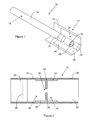
- the smoking article 10 shown in Figure 1 comprises a cylindrical tobacco rod 12 and a multi-component filter 14 aligned in end-to-end relationship with the tobacco rod 12.
- the tobacco rod 12 comprises a plug of tobacco cut filler circumscribed by a paper wrapper 16.
- the filter 14 is attached to the tobacco rod 12 by a band of tipping paper 18, which circumscribes the filter 14 and an adjacent portion of the tobacco rod 12.
- the multi-component filter 14 comprises a rod end filter segment 20 adjacent to and abutting the tobacco rod 12, a mouth end filter segment 22 at the mouth end of the smoking article 10 and a one piece, injection moulded flow restriction element 24 disposed between the rod end 20 and mouth end 22 filter segments.
- the rod end 20 and mouth end 22 filter segments are each formed of a plug of cellulose acetate tow.
- the rod end 20 and mouth end 22 filter segments are spaced apart from the opposed ends of the flow restriction element 24 by a small distance.
- the rod end 20 and mouth end 22 filter segments and the flow restriction element 24 are circumscribed by a band of plug wrap 26.
- the flow restriction element 24 is formed of polyvinyl alcohol which has been blended with an inorganic filler material and injection moulded to form the flow restriction element 24. As shown in Figure 2 , the flow restriction element 24 includes a central, transverse barrier 28, an integral downstream tubular portion 30 extending from the downstream side of the barrier 28 and an integral upstream tubular portion 32 extending from the upstream side of the barrier 28.
- the inner periphery of the downstream tubular portion 30 defines a downstream cavity 34 adjacent the transverse barrier 28, wherein the downstream cavity 34 is integral to the space between the transverse barrier 28 and the second filter segment 22.
- the inner periphery of the upstream tubular portion 32 similarly defines an upstream cavity 36 adjacent the transverse barrier 28 on the opposite side, wherein the downstream cavity 34 is integral to the space between the transverse barrier 28 and the first filter segment 20.
- the tubular portions 30, 32 are of approximately the same length as each other and both have an external diameter substantially corresponding to the outer diameter of the filter 14.
- the flow restriction element 24 is therefore substantially symmetrical about the transverse barrier 28.
- the transverse barrier 28 is in the form of a circular disc having an outer diameter substantially corresponding to the outer diameter of the filter 14.
- the circular disc includes a single, central orifice 38 that provides a passageway between the downstream cavity 34 and the upstream cavity 36.
- the orifice is substantially circular in cross-section and has a diameter of approximately 0.85 mm.
- the outer circumferential edges of the transverse barrier 28, the downstream tubular portion 30 and the upstream tubular portion 32 are integral such that the outer surface of the flow restriction element 24 as a whole is substantially cylindrical.
- the transverse barrier 28 and the walls of the tubular portions 30, 32 have a thickness of between 0.5 mm and 0.7 mm.
- the plug wrap 26 is affixed to the outer surfaces of the rod end 20 and mouth end 22 filter segments and the flow restriction element 24 by means of a suitable adhesive.
- a strip of adhesive is also provided along the inner surface at the edge of the plug wrap 26 in order to secure the plug wrap 16 in place along the seam, creating a lap joint.
- a circumferential row of perforations 40 is provided through the band of tipping paper 18 and the band of plug wrap 26.
- the perforations 40 are located at a position along the filter 14 upstream of the flow restriction element 24, overlying the rod end filter segment 20.
- ventilating air is drawn through the perforations 40 into the filter, where it mixes with mainstream smoke drawn through the central orifice 38 of the transverse barrier 28.
- the perforations 40 provide a level of dilution of the mainstream smoke of approximately 65% when the perforations are open. This level of dilution will decrease if the perforations become at least partially covered.
- the RTD of the smoking article 10 during smoking with the perforations blocked is within about 60% of RTD of the smoking article smoking with the perforations open.
Landscapes
- Cigarettes, Filters, And Manufacturing Of Filters (AREA)
Priority Applications (1)
| Application Number | Priority Date | Filing Date | Title |
|---|---|---|---|
| EP12164931.3A EP2653045A1 (fr) | 2012-04-20 | 2012-04-20 | Article à fumer comprenant un filtre avec élément de restriction de débit et ventilation en amont |
Applications Claiming Priority (1)
| Application Number | Priority Date | Filing Date | Title |
|---|---|---|---|
| EP12164931.3A EP2653045A1 (fr) | 2012-04-20 | 2012-04-20 | Article à fumer comprenant un filtre avec élément de restriction de débit et ventilation en amont |
Publications (1)
| Publication Number | Publication Date |
|---|---|
| EP2653045A1 true EP2653045A1 (fr) | 2013-10-23 |
Family
ID=46044408
Family Applications (1)
| Application Number | Title | Priority Date | Filing Date |
|---|---|---|---|
| EP12164931.3A Ceased EP2653045A1 (fr) | 2012-04-20 | 2012-04-20 | Article à fumer comprenant un filtre avec élément de restriction de débit et ventilation en amont |
Country Status (1)
| Country | Link |
|---|---|
| EP (1) | EP2653045A1 (fr) |
Cited By (6)
| Publication number | Priority date | Publication date | Assignee | Title |
|---|---|---|---|---|
| WO2015152072A1 (fr) * | 2014-03-31 | 2015-10-08 | 日本たばこ産業株式会社 | Filtre pour produit de tabac et produit de tabac |
| WO2016092284A1 (fr) * | 2014-12-08 | 2016-06-16 | British American Tobacco (Investments) Limited | Article à fumer, section de filtre d'article à fumer et procédé de fabrication d'article à fumer |
| WO2016092283A1 (fr) * | 2014-12-08 | 2016-06-16 | British American Tobacco (Investments) Limited | Article à fumer, filtre et procédé de fabrication d'un article à fumer |
| US20170360086A1 (en) * | 2014-12-08 | 2017-12-21 | British American Tobacco (Investments) Limited | A smoking article, a smoking article filter section and a method of manufacturing a smoking article |
| WO2019064021A1 (fr) * | 2017-09-29 | 2019-04-04 | British American Tobacco (Investments) Limited | Façonnage d'un produit de l'industrie du tabac |
| JP2023130469A (ja) * | 2018-11-14 | 2023-09-20 | 日本たばこ産業株式会社 | 非燃焼加熱喫煙物品および非燃焼加熱喫煙システム |
Citations (5)
| Publication number | Priority date | Publication date | Assignee | Title |
|---|---|---|---|---|
| EP0125027A1 (fr) * | 1983-04-07 | 1984-11-14 | Gallaher Limited | Dispositif d'embout pour une tige à fumer |
| US4506683A (en) * | 1983-05-09 | 1985-03-26 | Brown & Williamson Tobacco Corporation | Ventilated mouthpiece for a smoking article |
| EP2253231A1 (fr) * | 2009-05-18 | 2010-11-24 | Philip Morris Products S.A. | Article à fumer avec élément de restriction de flux amélioré |
| US20110083675A1 (en) * | 2009-10-09 | 2011-04-14 | Philip Morris Usa Inc. | Smoking article with valved restrictor |
| WO2011117754A2 (fr) * | 2010-03-26 | 2011-09-29 | Philip Morris Products S.A. | Produits à fumer à teneur très réduite en constituants à fumer en phase gaz et vapeur |
-
2012
- 2012-04-20 EP EP12164931.3A patent/EP2653045A1/fr not_active Ceased
Patent Citations (5)
| Publication number | Priority date | Publication date | Assignee | Title |
|---|---|---|---|---|
| EP0125027A1 (fr) * | 1983-04-07 | 1984-11-14 | Gallaher Limited | Dispositif d'embout pour une tige à fumer |
| US4506683A (en) * | 1983-05-09 | 1985-03-26 | Brown & Williamson Tobacco Corporation | Ventilated mouthpiece for a smoking article |
| EP2253231A1 (fr) * | 2009-05-18 | 2010-11-24 | Philip Morris Products S.A. | Article à fumer avec élément de restriction de flux amélioré |
| US20110083675A1 (en) * | 2009-10-09 | 2011-04-14 | Philip Morris Usa Inc. | Smoking article with valved restrictor |
| WO2011117754A2 (fr) * | 2010-03-26 | 2011-09-29 | Philip Morris Products S.A. | Produits à fumer à teneur très réduite en constituants à fumer en phase gaz et vapeur |
Cited By (11)
| Publication number | Priority date | Publication date | Assignee | Title |
|---|---|---|---|---|
| WO2015152072A1 (fr) * | 2014-03-31 | 2015-10-08 | 日本たばこ産業株式会社 | Filtre pour produit de tabac et produit de tabac |
| WO2016092284A1 (fr) * | 2014-12-08 | 2016-06-16 | British American Tobacco (Investments) Limited | Article à fumer, section de filtre d'article à fumer et procédé de fabrication d'article à fumer |
| WO2016092283A1 (fr) * | 2014-12-08 | 2016-06-16 | British American Tobacco (Investments) Limited | Article à fumer, filtre et procédé de fabrication d'un article à fumer |
| CN106998795A (zh) * | 2014-12-08 | 2017-08-01 | 英美烟草(投资)有限公司 | 吸烟制品、过滤器和制造吸烟制品的方法 |
| US20170360086A1 (en) * | 2014-12-08 | 2017-12-21 | British American Tobacco (Investments) Limited | A smoking article, a smoking article filter section and a method of manufacturing a smoking article |
| US20170360084A1 (en) * | 2014-12-08 | 2017-12-21 | British American Tobacco (Investments) Limited | A smoking article, a filter and a method of manufacturing a smoking article |
| RU2666218C1 (ru) * | 2014-12-08 | 2018-09-06 | Бритиш Америкэн Тобэкко (Инвестментс) Лимитед | Курительное изделие, секция фильтра курительного изделия и способ изготовления курительного изделия |
| RU2668750C1 (ru) * | 2014-12-08 | 2018-10-02 | Бритиш Америкэн Тобэкко (Инвестментс) Лимитед | Курительное изделие, фильтр и способ изготовления курительного изделия |
| WO2019064021A1 (fr) * | 2017-09-29 | 2019-04-04 | British American Tobacco (Investments) Limited | Façonnage d'un produit de l'industrie du tabac |
| US12543779B2 (en) | 2017-09-29 | 2026-02-10 | British American Tobacco (Investments) Limited | Shaping a tobacco industry product |
| JP2023130469A (ja) * | 2018-11-14 | 2023-09-20 | 日本たばこ産業株式会社 | 非燃焼加熱喫煙物品および非燃焼加熱喫煙システム |
Similar Documents
| Publication | Publication Date | Title |
|---|---|---|
| EP2753198B1 (fr) | Filtre d'article à fumer doté d'un élément de restriction de flux et d'une cavité | |
| EP2432338B1 (fr) | Article à fumer avec élément de restriction de flux amélioré | |
| US8235057B2 (en) | Smoking article with open ended filter and restrictor | |
| US8424540B2 (en) | Smoking article with valved restrictor | |
| EP2753199B1 (fr) | Filtre d'article à fumer incluant un insert polymère | |
| AU2012285567B2 (en) | Ventilated smoking article | |
| EP2653045A1 (fr) | Article à fumer comprenant un filtre avec élément de restriction de débit et ventilation en amont | |
| US10219540B2 (en) | Filter components, filters, smoking articles, and related methods, all for the controlled delivery of aerosols | |
| US20130112216A1 (en) | Tobacco smoke filter | |
| US10925311B2 (en) | Smoking article including flow restrictor | |
| US11510434B2 (en) | Smoking article with concentric filter | |
| HK1165233B (en) | Smoking article with improved flow restriction element | |
| HK1178754A (en) | Smoking article with open ended filter and restrictor |
Legal Events
| Date | Code | Title | Description |
|---|---|---|---|
| PUAI | Public reference made under article 153(3) epc to a published international application that has entered the european phase |
Free format text: ORIGINAL CODE: 0009012 |
|
| AK | Designated contracting states |
Kind code of ref document: A1 Designated state(s): AL AT BE BG CH CY CZ DE DK EE ES FI FR GB GR HR HU IE IS IT LI LT LU LV MC MK MT NL NO PL PT RO RS SE SI SK SM TR |
|
| AX | Request for extension of the european patent |
Extension state: BA ME |
|
| STAA | Information on the status of an ep patent application or granted ep patent |
Free format text: STATUS: THE APPLICATION HAS BEEN REFUSED |
|
| 18R | Application refused |
Effective date: 20131114 |