EP2653064B1 - Zusammenschiebbarer Behälter - Google Patents
Zusammenschiebbarer Behälter Download PDFInfo
- Publication number
- EP2653064B1 EP2653064B1 EP13164625.9A EP13164625A EP2653064B1 EP 2653064 B1 EP2653064 B1 EP 2653064B1 EP 13164625 A EP13164625 A EP 13164625A EP 2653064 B1 EP2653064 B1 EP 2653064B1
- Authority
- EP
- European Patent Office
- Prior art keywords
- base
- container
- top ring
- collapsible container
- ring
- Prior art date
- Legal status (The legal status is an assumption and is not a legal conclusion. Google has not performed a legal analysis and makes no representation as to the accuracy of the status listed.)
- Active
Links
- 238000000465 moulding Methods 0.000 claims description 36
- 238000000034 method Methods 0.000 claims description 20
- 238000004519 manufacturing process Methods 0.000 claims description 4
- 238000001746 injection moulding Methods 0.000 claims description 3
- 239000012260 resinous material Substances 0.000 claims description 2
- 230000002093 peripheral effect Effects 0.000 description 41
- 239000000463 material Substances 0.000 description 24
- 238000003860 storage Methods 0.000 description 8
- 230000036961 partial effect Effects 0.000 description 7
- 238000010276 construction Methods 0.000 description 5
- 235000013361 beverage Nutrition 0.000 description 4
- 238000002347 injection Methods 0.000 description 4
- 239000007924 injection Substances 0.000 description 4
- 238000012986 modification Methods 0.000 description 4
- 230000004048 modification Effects 0.000 description 4
- 230000006835 compression Effects 0.000 description 3
- 238000007906 compression Methods 0.000 description 3
- 229920000642 polymer Polymers 0.000 description 3
- 238000004026 adhesive bonding Methods 0.000 description 2
- 230000007423 decrease Effects 0.000 description 2
- 230000035622 drinking Effects 0.000 description 2
- 230000000694 effects Effects 0.000 description 2
- 235000013305 food Nutrition 0.000 description 2
- 230000006870 function Effects 0.000 description 2
- 239000011521 glass Substances 0.000 description 2
- 239000007788 liquid Substances 0.000 description 2
- 235000021156 lunch Nutrition 0.000 description 2
- 239000002991 molded plastic Substances 0.000 description 2
- 235000021178 picnic Nutrition 0.000 description 2
- 230000002829 reductive effect Effects 0.000 description 2
- 235000002017 Zea mays subsp mays Nutrition 0.000 description 1
- 241000482268 Zea mays subsp. mays Species 0.000 description 1
- 239000000853 adhesive Substances 0.000 description 1
- 230000001070 adhesive effect Effects 0.000 description 1
- 230000015572 biosynthetic process Effects 0.000 description 1
- 238000004140 cleaning Methods 0.000 description 1
- 239000003086 colorant Substances 0.000 description 1
- 230000003247 decreasing effect Effects 0.000 description 1
- 238000001125 extrusion Methods 0.000 description 1
- 239000010408 film Substances 0.000 description 1
- 229920002457 flexible plastic Polymers 0.000 description 1
- 238000004806 packaging method and process Methods 0.000 description 1
- 238000012856 packing Methods 0.000 description 1
- 230000000717 retained effect Effects 0.000 description 1
- 239000000243 solution Substances 0.000 description 1
- 238000005728 strengthening Methods 0.000 description 1
- 239000000126 substance Substances 0.000 description 1
- 229920001059 synthetic polymer Polymers 0.000 description 1
- 239000010409 thin film Substances 0.000 description 1
- 238000005406 washing Methods 0.000 description 1
- 230000003313 weakening effect Effects 0.000 description 1
Images




Classifications
-
- B—PERFORMING OPERATIONS; TRANSPORTING
- B65—CONVEYING; PACKING; STORING; HANDLING THIN OR FILAMENTARY MATERIAL
- B65D—CONTAINERS FOR STORAGE OR TRANSPORT OF ARTICLES OR MATERIALS, e.g. BAGS, BARRELS, BOTTLES, BOXES, CANS, CARTONS, CRATES, DRUMS, JARS, TANKS, HOPPERS, FORWARDING CONTAINERS; ACCESSORIES, CLOSURES, OR FITTINGS THEREFOR; PACKAGING ELEMENTS; PACKAGES
- B65D21/00—Nestable, stackable or joinable containers; Containers of variable capacity
- B65D21/08—Containers of variable capacity
-
- A—HUMAN NECESSITIES
- A45—HAND OR TRAVELLING ARTICLES
- A45F—TRAVELLING OR CAMP EQUIPMENT: SACKS OR PACKS CARRIED ON THE BODY
- A45F3/00—Travelling or camp articles; Sacks or packs carried on the body
- A45F3/16—Water-bottles; Mess-tins; Cups
- A45F3/20—Water-bottles; Mess-tins; Cups of flexible material; Collapsible or stackable cups
-
- A—HUMAN NECESSITIES
- A47—FURNITURE; DOMESTIC ARTICLES OR APPLIANCES; COFFEE MILLS; SPICE MILLS; SUCTION CLEANERS IN GENERAL
- A47G—HOUSEHOLD OR TABLE EQUIPMENT
- A47G19/00—Table service
- A47G19/22—Drinking vessels or saucers used for table service
-
- B—PERFORMING OPERATIONS; TRANSPORTING
- B29—WORKING OF PLASTICS; WORKING OF SUBSTANCES IN A PLASTIC STATE IN GENERAL
- B29C—SHAPING OR JOINING OF PLASTICS; SHAPING OF MATERIAL IN A PLASTIC STATE, NOT OTHERWISE PROVIDED FOR; AFTER-TREATMENT OF THE SHAPED PRODUCTS, e.g. REPAIRING
- B29C45/00—Injection moulding, i.e. forcing the required volume of moulding material through a nozzle into a closed mould; Apparatus therefor
- B29C45/14—Injection moulding, i.e. forcing the required volume of moulding material through a nozzle into a closed mould; Apparatus therefor incorporating preformed parts or layers, e.g. injection moulding around inserts or for coating articles
-
- A—HUMAN NECESSITIES
- A45—HAND OR TRAVELLING ARTICLES
- A45F—TRAVELLING OR CAMP EQUIPMENT: SACKS OR PACKS CARRIED ON THE BODY
- A45F3/00—Travelling or camp articles; Sacks or packs carried on the body
- A45F3/16—Water-bottles; Mess-tins; Cups
- A45F3/20—Water-bottles; Mess-tins; Cups of flexible material; Collapsible or stackable cups
- A45F2003/205—Collapsible or foldable cups
Definitions
- the present invention generally relates to molded plastic containers of the type commonly used for a variety of purposes including storage of both food items and non-food items, such containers preferably being adapted to receive an appropriate seal or lid. More specifically, the invention is concerned with containers of this type which, rather than being of a rigid construction as with a conventional container, are collapsible or foldable to a compact position when empty to facilitate convenient use and storage.
- Such containers in the form of tumblers, cups, bowls, and the like, are generally known in the art and take many forms. These include collapsible cups or glasses wherein the glass is formed of telescopically stacked annular wall elements which slide relative to each other between a fully extended position and a collapsed position. As the wall elements are not integrally formed and slide freely relative to each other, there is a substantial possibility of leakage, and use, other than as a temporary drinking vessel, is not practical.
- angularly related multiple folding sections extend at an angle to the vertical, and include, within each section itself, a "flexure zone" adjacent the angular joint between adjacent sections and flexibly movable between a first open position in the expanded container and a second position folded upon itself in the collapsed container.
- the flexure zones resist movement of the sections in both the fully expanded container and the collapsed container, as well as any intermediate position wherein only selected flexure zones are in an open position.
- the wall elements are integrally molded in a single molding step, and comprise a plurality of annular and relatively thick wall sections alternating with annular thin wall sections, all of which are of successively decreasing diameter from the top to the bottom of the cup. Due to the fact that the body is made of a flexible plastic material, the thin wall sections are relatively more flexible than the thick wall sections, and each thin wall section will consequently reversely move over itself into an inside out or inverted position, when the thick wall sections of different diameters are moved into telescopic relation. With the single molding step described by Owsen, however, there is no possibility to obtain an optimal hardness to softness ratio for the annular sections of a collapsible cup, which can be achieved through the use of two different materials in a multiple injection molding process.
- a collapsible container is also shown in U.S. Patent No. 5,575,398, issued to Robbins, III on November 19, 1996 .
- the Robbins, III container is also extrusion or blow molded in a single molding step, and comprises a bottom wall and relatively flexible peripheral side walls extending upwardly from the bottom wall, the side walls being connected by areas of reduced side wall thickness, to facilitate the collapsing of the container.
- US 2010/0183773 A1 discloses a packaging assembly, especially for popcorn, which expands from a collapsed state to an extended state and which comprises a flexible sidewall.
- a collapsible container has not heretofore particularly lent itself to formation from two materials of differing hardness, flexibility, or rigidity, in the collapsible section of the container. This allows the container to be collapsed with less force than is required for existing containers having a collapsible section comprised of only one type of material, and is particularly desirable where the container is to be used by children or elderly persons having limited mobility or dexterity in their hands and/or fingers.
- a collapsible container (10) preferably selected from the group consisting of a cup, tumbler, and bowl, having a plurality of sections, said collapsible container comprising:
- the sections include a lowermost section joined to said base, a topmost section joined to said top ring, and intermediate sections between said lowermost and topmost sections, said sections, from said lowermost section to said topmost section each sequentially defining a peripherally encompassed area generally progressively greater than the base.
- said lowermost section joined to said base comprises said flexible wall
- said topmost section joined to said top ring comprises said flexible wall
- a foot (24) is disposed on said base, and preferably wherein the foot is molded separately from the base, or wherein the foot is molded integrally with the base.
- said flexible wall includes a central corrugated area (32).
- said central corrugated area is bordered by a corrugation-free stress relief area.
- said top ring includes an upwardly extending ring wall (28), and a separate seal (46) disposed on said top ring and being releasably fixed to said ring wall in both the expanded and collapsed position of said collapsible container.
- said base has a bottom surface (20) defining a support plane, said top ring and intermediate ring or rings in the collapsed position of the collapsible container being positioned above said defined support plane.
- said top ring includes a circumferential outwardly extending flange (30) defining a means for grasping the top ring as downward pressure is applied to said base.
- said top ring includes an upwardly extending ring wall (28), and a separate seal (46) positionable over said top ring and being releasably fixed to said ring wall in both the expanded and collapsed position of said collapsible container.
- the flexible wall is laterally folded on a rigid ring immediately below in the collapsed position of the collapsible container.
- said central corrugated area comprises living hinges, and preferably wherein said living hinges are formed from a narrowing (A) of the flexible wall, or wherein a section comprising the flexible wall comprises three living hinges, which are optionally formed from three different thicknesses of the flexible wall.
- a method of making a collapsible container comprising the steps of: molding, in a first step, the base component, the one or more intermediate ring components, and the top ring component; and over molding, in a second step, the flexible wall component onto said base, one or more intermediate ring components, and top component, to form said collapsible container, preferably wherein said first and second molding steps are carried out using synthetic resinous material, and/or optionally wherein said first and second, molding steps are carried out in at least two molding apparatuses, and/or optionally wherein said first and second molding steps are an injection molding.
- the method further comprises the step of incorporating a color in at least one of the base, one or more intermediate ring, top ring, and flexible wall.
- the base, one or more intermediate ring, top ring, and flexible wall are molded in five different molding steps using five different molding apparatuses.
- a principal object of the present invention is to provide a collapsible container which presents or forms a substantially rigid receptacle in its open or expanded position and which, with an appropriate watertight lid or seal snap-fitted thereto, provides a practical watertight storage container for, as an example, an appropriate beverage, or the like.
- the container is very convenient and provides a particularly desirable portable solution for drinks "on-the-go", such as at picnics, lunches for those who take their own lunch to work, and other instances wherein temporary storage of liquids is desired.
- the collapsible nature of the container collapsing to a substantially completely compacted configuration of minimal height, particularly with a watertight seal mounted thereon to confine any residue in the now empty container, allows the used container to be conveniently stored or packed away in a "brown bag", knapsack, picnic hamper, or the like, for subsequent cleaning and reuse.
- Another significant aspect of the container of the invention is its capability to fold open in increments, one section at a time, to vary the capacity thereof and to maintain its incrementally folded position.
- Another significant aspect of the invention is the optional provision of a foot extending from the base of the container, which assists the user in extending the container from its collapsed or folded configuration to an expanded position, without contaminating the inside surfaces of the container that will come into contact with the beverage, or the like. This is particularly desirable where the container is used to store beverages, or other foodstuffs, for infants and children, where an uncontaminated environment is particularly desirable.
- Another significant aspect of the invention is the provision of two materials of differing hardness, flexibility, or rigidity in the collapsible section of the container. This allows the container to be collapsed with less force than is required for existing containers having a collapsible section comprised of only one type of material, and is particularly desirable where the container is to be used by children or elderly persons having limited mobility or dexterity in their hands and/or fingers.
- Another significant aspect of the invention is the provision of a collapsible container design that will allow a more vertical sidewall, compared to existing collapsible containers, as is typically required, and more advantageous, for a tumbler for drinking.
- a container which can be washed in a dishwasher in its collapsed or expanded configuration, and stacked economically therein in the same manner as conventional dishes; a container which stays open when in use and stays closed in storage; and a container which maximizes usable space for packing in a shipping carton as well as storage in the home.
- the peripheral wall of the container extending between a substantially hard, rigid base and a substantially hard, rigid top ring adapted to receive a snap-fit seal, includes a series of generally hard, rigid annular or peripherally continuous wall sections intimately bonded to the flexible or soft peripheral wall.
- the resulting container wall thus comprises alternating sections that are soft and flexible relative to the rigid annular wall sections, and relative to the base and top ring.
- the rigid wall sections and soft wall sections, in the expanded or open position of the container, and sequentially upwardly from the base to the top ring, are each generally diametrically or peripherally progressively greater than the base.
- the configuration thus formed for the expanded container will be that of an inverted truncated cone with the wall sections basically outwardly stepped upward from the base. This, in turn, allows for a direct downward collapsing of the wall sections into concentric surrounding relation to the base with the top ring surrounding the collapsed wall sections.
- each of the flexible wall sections includes a central corrugated area which, in transverse cross section, comprises flexible wall material of alternating thicknesses, producing a plurality of horizontal corrugations on the outside surface of the flexible wall sections, the area between each adjacent corrugation being defined by a "living hinge".
- these corrugations direct the flexible wall sections to flex and collapse in the desired direction and manner when physical force is applied to the base and top ring.
- the flexible wall sections would "jam” in the process of collapsing the container, requiring the user to manipulate each ring individually.
- the corrugations also provide friction between the flexible and rigid wall sections in the collapsed or folded configuration of the container, to achieve and maintain the minimum height of the container in the collapsed or folded position.
- Each of the flexible wall sections also includes upper and lower corrugation-free or "stress relief” areas on either side of the central corrugated area. These stress relief areas assist in maintaining the container in its minimum collapsed height, by relieving stress in the flexible wall material at the point where the flexible wall section folds back on itself as the container is collapsed, as will be more fully explained. The presence, otherwise, of a corrugation at this position would produce additional compression stress that would tend to relieve itself by extending the container upward somewhat from its collapsed configuration.
- the size of the stress relief area is critical in that, if this area is too great, the flexible wall sections will "jam" while in the process of collapsing, due to a lack of direction provided by the corrugations, as aforementioned. Conversely, if the stress relief area is too small, the compression stress in the collapsed position will tend to extend the container from its collapsed position.
- each of the flexible wall sections in a first embodiment, the application of a positive physical force collapsing the top ring and base toward each other causes each of the flexible wall sections to reversely move over itself into an inside out or inverted position, as the top ring, intermediate ring sections, and base, all of different diameters, are moved into telescopic relation.
- This inverting of each flexible wall section over itself and onto the adjacent intermediate ring section or base begins at a stress relief area located toward the lower peripheral edge of each soft wall section.
- each flexible wall section continues to roll back over itself and onto the adjacent intermediate ring section or base, as the top ring, intermediate rings, and base are moved into telescopic relation. In this way, the container will collapse telescopically as each flexible wall section folds over the intermediate ring or base section below.
- collapsible container of the invention also may take the form of a cup or bowl, and like receptacles, which are also considered to be within the scope of the claimed invention.
- the foregoing goals of the invention are basically achieved by at least a two-step method or process of molding, normally referred to as a co-injection process.
- the practice of the co-injection process of the present invention may be characterized as a multi-injection "2C", i.e., two component, process.
- a rigid base component, a rigid top ring component, and rigid intermediate ring components are molded, and then, in a second molding step, a flexible wall component is over-molded and bonded to the rigid top, base and intermediate ring components, to form the container.
- the bonding may be via chemical adhesion of an autogenous or adhesive nature.
- a five-step molding process could be used, in which the base is molded in a first step, the lower intermediate ring is molded in a second molding step, the upper intermediate ring is molded in a third molding step, the top ring is molded in a fourth molding step, and the peripheral wall is over-molded and bonded to the top, base, and intermediate ring components in a fifth molding step.
- a four-step molding method would be required to manufacture a collapsible container of the invention having a single intermediate ring, rather than two intermediate rings.
- the base, intermediate rings, top ring, and peripheral wall can be transparent, translucent or opaque, and may have color.
- materials having different degrees of opacity and different colors can be used, in order to make the finished article aesthetically pleasing to a consumer.
- each of the base, intermediate rings, top ring, and peripheral wall is molded in a separate step, using materials of different color.
- the container is molded in the open or expanded configuration, which will result in material memory that tends toward an open or expanded position of the container. This makes the final container product less prone to unintentional collapsing, and accordingly a safer product, especially when the container is used to hold, store, or transport hot liquids.
- a first embodiment of the collapsible container 10 comprises a base 12, a top ring 14, and a plurality of substantially rigid intermediate rings 16 disposed therebetween.
- the peripheral wall 18 of the container 10, which extends from the base 12 to the top ring 14, comprises a soft, flexible material that is over-molded to the base 12, top ring 14, and rigid intermediate rings 16, to form the collapsible container 10, as will be described more fully below.
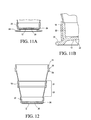
- only one intermediate ring 16 is present in the container wall ( Figure 12 ).
- the flexible material of the peripheral wall 16 may also be defined as being pliable, bendable, and/or foldable.
- the base 12 is a substantially rigid member including a flat bottom 20 and a peripheral upstanding base wall 22.
- the base 20, which preferably may be slightly upwardly convex toward the top of the container 10, as shown in Figures 4 and 5 , optionally may include a foot 24 depending from the base bottom 20, to provide a stable platform for the container 10, and to assist in expanding the container, as shall be described subsequently.
- the foot 24 is preferably molded as a separate component, as shown in Figure 11B , and then permanently secured to the base 12, for example by bonding or gluing.
- the foot 24 may be integrally molded with the base, as shown in Figure 11B .
- the base 12 will also optionally have a continuous, circular foot rib 26 depending from the base bottom 20, to which the foot 24 is secured.
- the top ring 14 includes a continuous or annular ring wall 28, and a peripheral, horizontally outwardly directed flange 30 at approximately mid-height on the ring wall 28.
- the top ring 14, similar to the base 12, is substantially hard or rigid, and is of a greater diameter than the base 12 to encircle the base 12 in the collapsed position of the container 10, as shown in Figures 2 and 5 , sufficiently outward thereof to accommodate the collapsed container wall therebetween.
- the top ring flange 30 provides additional lateral stiffness to the top ring, as well as a convenient means for handling the container, especially when filled.
- top ring flange 30 when the collapsed container is to be opened, allows a user to easily engage fingers of one hand about and under this flange 30 while pulling downward with the fingers of the other hand on the foot 24, to forcibly vertically expand the base and top ring relative to each other.
- the peripheral wall 18 is formed of soft or flexible material, and is over-bonded to the top ring 14 and base 20, respectively, at the upper and lower peripheral boundaries of the wall, and to the intermediate rings 16 in the central portion of the container.
- the container is thus made up of a series of annular or peripherally continuous wall sections of flexible wall material 32, alternating with rigid rings over-molded with flexible wall material 34.
- each of the flexible wall sections 32 includes corrugations 36 in the central area thereof which, in transverse cross section, comprise flexible wall material of alternating thicknesses, producing a plurality of horizontal corrugations on the outside surface of the flexible wall sections 32.
- the corrugations 36 direct the flexible wall sections 32 to flex and collapse in the desired direction and manner when physical force is applied to the base 12 and top ring 14, as will be explained more fully.
- This thinner peripheral wall section, or living hinge, is present in the flexible wall material 32 located between the top ring 14 and upper intermediate ring 16, between the upper and lower intermediate rings 16, and between the lower intermediate ring 16 and the base 12.
- the thinner peripheral wall area A results in a tendency for the wall section to begin to collapse at the location of the thinner wall area A. It will be appreciated that locating the thinner living hinge towards the middle of the wall section 32 promotes a more controlled collapse as pressure is applied to the container.
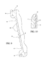
- each of the flexible wall sections 32 also includes upper 40 and lower 42 corrugation-free or "stress relief” areas on either side of the central corrugated area 36.
- These stress relief areas 40, 42 assist in maintaining the container 10 in its minimum collapsed height, by relieving stress in the flexible wall material at the point where the flexible wall section 32 folds back on itself as the container is collapsed, particularly noting Figure 10 in this regard. The presence, otherwise, of a corrugation at these positions would produce additional compression stress, that would tend to relieve itself by extending the container upward somewhat from its collapsed configuration.
- the lowermost section of the peripheral wall 18 encircles and is intimately bonded to the wall 22 of base 12, continuing under the inwardly curved lower peripheral edge of the base 12, and terminating at the location of the downwardly extending foot rib 26 located on the bottom 20 of the base 12.
- the peripheral wall 18 is intimately bonded to the base 12 , for example autogenously, during a multi-component molding procedure.
- the container wall sections upward from engagement of the lowermost section 32 with the base 12, are thus alternately sections of flexible wall material, designated sections 32, alternating with rigid rings over-molded with flexible wall material, designated sections 34.
- peripheral wall 18 terminates in an upwardly directed collar 44 received and intimately fixed to the lower edge portion of the ring wall 28 below flange 30, for example, in the manner suggested with regard to the lowermost section.
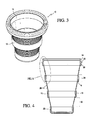
- Figure 3 is of particular interest in showing the container partially collapsed for use when a reduced capacity is desired or required.
- the container In the configuration shown, only the uppermost flexible wall section 32 is shown collapsed onto the rigid wall section 34 immediately below. In such a position, the container is fully functional to receive and store foodstuffs and the like, and the seal 42, as in the open container of Figure 3 , is also fully functional in that the top ring is dimensionally stable in every position of the container.
- a seal 46 is capable of being snap-fitted to the top ring 14 in an appropriate manner in any position assumed by the container.
- the upper portion 48 of the top ring wall 28, above the circumferential flange 30, may be slightly outwardly inclined for reception within a peripheral downwardly directed groove on the inner surface of the seal 46. It is to be appreciated that inasmuch as the wall sections 32, 34 are, in any position of the container, positioned concentrically inward of the substantially rigid top ring 14, the seal 46 functions as an appropriate closure for the open container, the partially expanded container, and the collapsed container wherein a compacted storage position is achieved.
- FIG. 13 to 18 A second embodiment of the collapsible container 10 is shown in Figures 13 to 18 , wherein elements which are common to the first embodiment of the invention are indicated by like reference numerals.
- the base 12, top ring 14, peripheral wall 18, base bottom 20, and plurality of substantially rigid intermediate rings 16, are manufactured and configured substantially as shown and described hereinabove for the first embodiment depicted in Figures 1 to 12 .
- the collapsible container of the second embodiment of the invention may also optionally include a foot 24, depending from the base bottom 20, which is preferably molded as a separate component, as shown in Figure 11B , and then permanently secured to the base 12, for example by bonding or gluing.
- the foot 24 may be integrally molded with the base, as shown in Figure 11B .
- each of the flexible wall sections 32 includes corrugations 50A, 50B, 50C, and 50D, in the central area thereof which, in transverse cross section, comprise bands of flexible wall material of different thicknesses, producing a plurality of angled corrugations on the outside surface of the flexible wall sections 32.
- the height of the corrugation 50B below the upper living hinge 58 is approximately twice the height of the corrugation 50A above the living hinge 58, on one side of the container.
- the height of the corrugation 50B above the upper living hinge 58 is approximately twice the height of the corrugation 50A below the living hinge 58.
- the height of the corrugations (50A, 50B, 50C, 50D) above and below the angled upper 58 and lower 60 living hinges decreases (or increases) from one side of the container to the other.
- the height of the corrugations above and below the upper 58 and lower 60 living hinges will be approximately equal.
- corrugations 50B, 50D that are stiffer than the adjacent shorter corrugations 50A, 50C. It appears that the controlled collapse of the container is facilitated by a combination of the thinner hinge 56 and the thicker (stiffer) corrugations 50B, 50C on one side of the container to the other.
- Each of the flexible wall sections 32 includes upper 52 and lower 54 corrugation-free or "stress relief” areas bounding the central corrugated area. As with the first embodiment of the invention, these stress relief areas 52, 54 assist in maintaining the container 10 in its minimum collapsed height, by relieving stress in the flexible wall material at the point where the flexible wall section 32 folds back on itself as the container is collapsed.
- the central corrugated area is formed of a series of four corrugations 50 connected to one another by central 56, upper 58, and lower 60 living hinges, as will be explained more fully.
- the upper 58 and lower 60 living hinges are angled with respect to the horizontal plane of the container, while the central living hinge 56 is substantially horizontal with respect to the horizontal plane.
- the thickness of the peripheral wall 18 forming living hinges 56, 58, and 60 is different for each living hinge. More particularly, the thickness of the peripheral wall 18 at the location of the central living hinge 56 is less than the thicknesses of the peripheral wall 18 at the location of both the upper 58 and lower 60 living hinges. Further, the thickness of the peripheral wall 18 at the location of the upper living hinge 58 is greater than the thickness of the peripheral wall at the location of the lower 60 living hinge. This arrangement results in the peripheral wall 18 being thinnest at the location of the central living hinge 56, and thickest at the location of the upper living hinge 58.
- the thickness of the peripheral wall 18 at the location of the upper living hinge 58 is 0.58 mm (0.023 in); the thickness of the peripheral wall 18 at the location of the central living hinge 56 is 0.38 mm (0.015 in); and the thickness of the peripheral wall 18 at the location of the lower living hinge 60 is 0.48 mm (0.019 in).
- the living hinge thickness could be as thin as 0.25 mm (0.010 in), and can be as thick as 0.76 mm (0.030 in).
- the flexible wall section 32 having the greatest diameter namely, the flexible wall section immediately below the top ring 14 will be the first flexible wall section to collapse as physical force is applied.
- the flexible wall section 32 having the second greatest diameter namely, the flexible wall section between the two intermediate rings 16 will be the next flexible wall section to collapse as physical force is applied.
- the flexible wall section 32 having the least diameter namely, the flexible wall section immediately above the base 12 will be the last flexible wall section to collapse as physical force is applied.
- the living hinge with the thinnest peripheral wall namely, the central living hinge 56
- the lower living hinge 60 which is the second thinnest living hinge
- the living hinge having the thickest peripheral wall namely, the upper living hinge 58 will be the last to collapse.
- sequence of collapse of the container cannot be precisely ascertained, and the sequence that occurs in use will depend on a combination of a number of factors, including, for example, the extent of the physical force applied to the base 12 and top ring 14, the manner in which the user grasps the base 12 and top ring 14, and the angle at which physical force is applied as the user pushes the base 12 and top ring 14 toward each other.
- the container when the container is to be expanded or opened prior to use, one need merely engage fingers of one hand about peripheral flange 30 of the top ring 14 and, with fingers of the other hand engaged about base 12, or the rim or flanged area of the foot 24, exert a downward pull on the base 12 or foot 24 to partially or fully expand the container 10. It will be appreciated that, with the seal 46 fitted onto the top ring 14 of the container 10, the container can be opened or expanded without contaminating the inner surfaces of the container 10 which will come into contact with beverages or foodstuffs.
- the collapsed wall sections and top ring are retained slightly above a support plane defined by the base bottom 20, rather than on the collapsed wall sections of the collapsed container 10.
- the container 10 of the invention is preferably molded in the open or expanded configuration. Open is thus the natural state for the container, that is the container would 'prefer' to remain open than in any other position.
- the container of the invention may be molded in a flattened or collapsed position.
- the unique structure of the invention allows the container to remain flat when in the closed or collapsed position, and remain expanded when in any open or partially open position.
- the relative hardness of the rigid intermediate rings 16 compared to the flexible wall sections 32, and the strengthening effect provided by the corrugations 36 present in the flexible wall sections 32, provide the necessary structural support to keep the container open when expanded.
- the container 10 prefers to remain closed when collapsed flat, and prefers to remain open when expanded.
- the container is capable of opening to fixed partial capacities by folding over of one or more flexible wall sections 32 onto its associated rigid wall section 34 below, because the container prefers to remain open in these partial configurations. This is of particular value in maximizing and optimizing storage space as in a refrigerator, and dishwasher space when washing.
- the collapsible container 10 of the present invention has been described in the preferred embodiment as comprising one of molded plastic, i.e. synthetic polymers, having 'separate entities' comprising a base 12, top ring 14, intermediate rings 16, and peripheral wall 18.
- the 'separate entities' in a preferred molding method may, for example, be realized by utilization of a molding apparatus that enables multiple stage molding of the base 12, top ring 14, intermediate rings 16, and peripheral wall 18, and wherein selection of polymers of varying degrees of substantial rigidity and/or general rigidity may be utilized. This also enables the varying of the color or light transmissivity of the base 12, top ring 14, intermediate rings 16, and peripheral wall 18.
- the molding of the base 12, top ring 14, and intermediate rings 16 as separate entities from the peripheral wall 18 is a preferred method of molding, enabling the provision of substantially greater rigidity to these components relative to the flexible wall sections 32, wherein the actual extending and collapsing action occurs by utilization of polymers of differing degrees of rigidity, and/or flexibility.
Landscapes
- Engineering & Computer Science (AREA)
- Mechanical Engineering (AREA)
- Manufacturing & Machinery (AREA)
- Containers Having Bodies Formed In One Piece (AREA)
- Rigid Containers With Two Or More Constituent Elements (AREA)
- Details Of Rigid Or Semi-Rigid Containers (AREA)
- Containers And Packaging Bodies Having A Special Means To Remove Contents (AREA)
Claims (15)
- Zusammenschiebbarer Behälter (10), vorzugsweise ausgewählt aus der Gruppe bestehend aus einem Becher, einem Trinkglas und einer Schale, aufweisend eine Mehrzahl von Abschnitten, wobei besagter zusammenschiebbarer Behälter Folgendes umfasst:einen starren oberen Ring (14);eine starre Basis (12);einen oder mehrere starre Zwischenringe (16), die zwischen besagtem oberem Ring und besagter Basis angeordnet sind; undeine flexible Wand (18), die peripher an besagter Basis, besagtem oberem Ring und besagtem einem oder mehreren Zwischenringen befestigt ist;worin besagter zusammenschiebbarer Behälter zwischen einer expandierten Position, bei der der obere Ring von besagter Basis nach oben beabstandet ist und einen Behälterinnenraum bildet, und einer zusammengeschobenen Position einstellbar ist, bei der besagter oberer Ring besagte Basis in einer nach außen beabstandeten, im Wesentlichen konzentrischen Beziehung zu dieser umgibt, dadurch gekennzeichnet, dass die flexible Wand durch Umspritzen an besagter Basis, besagtem oberem Ring und besagtem einem oder mehreren Zwischenringen peripher befestigt ist.
- Zusammenschiebbarer Behälter nach Anspruch 1, worin die Abschnitte einen untersten mit besagter Basis verbundenen Abschnitt, einen obersten mit besagtem oberem Ring verbundenen Abschnitt und Zwischenabschnitte zwischen besagten untersten und obersten Abschnitten beinhalten, wobei besagte Abschnitte, vom besagten untersten Abschnitt bis zum besagten obersten Abschnitt, jeweils sequentiell einen peripher umschlossenen Bereich, generell fortschreitend größer als die Basis, definieren.
- Zusammenschiebbarer Behälter nach Anspruch 2, worin besagter unterster mit besagter Basis verbundener Abschnitt besagte flexible Wand umfasst und besagter oberster mit besagtem oberem Ring verbundener Abschnitt besagte flexible Wand umfasst.
- Zusammenschiebbarer Behälter nach irgendeinem vorhergehenden Anspruch, worin ein Fuß (24) auf besagter Basis angeordnet ist und vorzugsweise worin der Fuß separat von der Basis geformt ist oder worin der Fuß integral mit der Basis geformt ist.
- Zusammenschiebbarer Behälter nach irgendeinem vorhergehenden Anspruch, worin besagte flexible Wand einen zentralen gewellten Bereich (32) beinhaltet.
- Zusammenschiebbarer Behälter nach Anspruch 5, worin besagter zentraler gewellter Bereich an einen wellungsfreien Spannungsabbaubereich angrenzt.
- Zusammenschiebbarer Behälter nach irgendeinem vorhergehenden Anspruch, worin besagter oberer Ring eine sich aufrecht erstreckende Ringwand (28) und eine separate Abdichtung (46) beinhaltet, die auf besagtem oberem Ring angeordnet ist und lösbar an besagter Ringwand in sowohl der expandierten als auch der zusammengeschobenen Position des besagten zusammenschiebbaren Behälters befestigt ist.
- Zusammenschiebbarer Behälter nach irgendeinem vorhergehenden Anspruch, worin besagte Basis eine Bodenfläche (20), die eine Unterstützungsebene definiert, aufweist, wobei besagter oberer Ring und Zwischenring oder -ringe in der zusammengeschobenen Position des zusammenschiebbaren Behälters oberhalb besagter definierter Unterstützungsebene positioniert sind.
- Zusammenschiebbarer Behälter nach irgendeinem vorhergehenden Anspruch, worin besagter oberer Ring einen umfänglichen, sich nach außen erstreckenden Flansch (30) beinhaltet, der ein Mittel zum Greifen des oberen Rings definiert, wenn Abwärtsdruck auf besagte Basis beaufschlagt wird.
- Zusammenschiebbarer Behälter nach irgendeinem vorhergehenden Anspruch, worin besagter oberer Ring eine sich aufrecht erstreckende Ringwand (28) und eine separate Abdichtung (46) beinhaltet, die über besagtem oberem Ring positionierbar ist und lösbar an besagter Ringwand in sowohl der expandierten als auch der zusammengeschobenen Position des besagten zusammenschiebbaren Behälters befestigt ist.
- Zusammenschiebbarer Behälter nach irgendeinem vorhergehenden Anspruch, worin die flexible Wand seitlich auf einem starren Ring unmittelbar darunter in der zusammengeschobenen Position des zusammenschiebbaren Behälters gefaltet ist.
- Zusammenschiebbarer Behälter nach irgendeinem vorhergehenden Anspruch, worin besagter zentraler gewellter Bereich aktive Scharniere umfasst, und vorzugsweise worin besagte aktive Scharniere aus einer Verengung (A) der flexiblen Wand gebildet sind, oder worin ein Abschnitt umfassend die flexible Wand drei aktive Scharniere umfasst, die wahlweise aus drei verschiedenen Dicken der flexiblen Wand gebildet sind.
- Verfahren zum Herstellen eines zusammenschiebbaren Behälters nach Anspruch 1, wobei das Verfahren die folgenden Schritte umfasst:Formen, in einem ersten Schritt, der Basiskomponente, der einen oder mehreren Zwischenringkomponenten und der oberen Ringkomponente; undUmspritzen, in einem zweiten Schritt, der flexiblen Wandkomponente an besagter Basis, einer oder mehrerer Zwischenringkomponenten und der oberen Komponente, um besagten zusammenschiebbaren Behälter zu bilden, vorzugsweise, worin besagte erste und zweite Formungsschritte unter Verwendung von synthetischem Harzmaterial ausgeführt werden, und/oder wahlweise worin besagte erste und zweite Formungsschritte in zumindest zwei Formungsvorrichtungen ausgeführt werden, und/oder wahlweise worin es sich bei besagten ersten und zweiten Formungsschritten um Spritzgießen handelt.
- Verfahren nach Anspruch 13, ferner umfassend den Schritt des Einbeziehens einer Farbe in zumindest eines von Basis, einem oder mehreren Zwischenringen, oberem Ring und flexibler Wand.
- Verfahren nach Anspruch 13 oder Anspruch 14, worin nur eine Zwischenringkomponente geformt wird, und/oder worin die Basis, ein oder mehrere Zwischenringe, oberer Ring und flexible Wand in fünf verschiedenen Formungsschritten unter Verwendung fünf verschiedener Formungsvorrichtungen geformt werden.
Priority Applications (2)
| Application Number | Priority Date | Filing Date | Title |
|---|---|---|---|
| EP15187253.8A EP2997849B1 (de) | 2012-04-20 | 2013-04-22 | Zusammenschiebbarer behälter |
| PL15187253T PL2997849T3 (pl) | 2012-04-20 | 2013-04-22 | Składany pojemnik |
Applications Claiming Priority (1)
| Application Number | Priority Date | Filing Date | Title |
|---|---|---|---|
| US13/452,240 US9044082B2 (en) | 2012-04-20 | 2012-04-20 | Collapsible container |
Related Child Applications (2)
| Application Number | Title | Priority Date | Filing Date |
|---|---|---|---|
| EP15187253.8A Division-Into EP2997849B1 (de) | 2012-04-20 | 2013-04-22 | Zusammenschiebbarer behälter |
| EP15187253.8A Division EP2997849B1 (de) | 2012-04-20 | 2013-04-22 | Zusammenschiebbarer behälter |
Publications (2)
| Publication Number | Publication Date |
|---|---|
| EP2653064A1 EP2653064A1 (de) | 2013-10-23 |
| EP2653064B1 true EP2653064B1 (de) | 2015-11-25 |
Family
ID=48139835
Family Applications (2)
| Application Number | Title | Priority Date | Filing Date |
|---|---|---|---|
| EP13164625.9A Active EP2653064B1 (de) | 2012-04-20 | 2013-04-22 | Zusammenschiebbarer Behälter |
| EP15187253.8A Active EP2997849B1 (de) | 2012-04-20 | 2013-04-22 | Zusammenschiebbarer behälter |
Family Applications After (1)
| Application Number | Title | Priority Date | Filing Date |
|---|---|---|---|
| EP15187253.8A Active EP2997849B1 (de) | 2012-04-20 | 2013-04-22 | Zusammenschiebbarer behälter |
Country Status (12)
| Country | Link |
|---|---|
| US (1) | US9044082B2 (de) |
| EP (2) | EP2653064B1 (de) |
| KR (1) | KR20130118814A (de) |
| CN (1) | CN103373515B (de) |
| AR (1) | AR090734A1 (de) |
| AU (1) | AU2013202079A1 (de) |
| BR (1) | BR102013007688A2 (de) |
| CA (1) | CA2810347A1 (de) |
| HU (1) | HUE039565T2 (de) |
| MX (1) | MX337336B (de) |
| MY (1) | MY164668A (de) |
| PL (1) | PL2997849T3 (de) |
Cited By (1)
| Publication number | Priority date | Publication date | Assignee | Title |
|---|---|---|---|---|
| RU179566U1 (ru) * | 2017-08-01 | 2018-05-17 | Алексей Аркадьевич Мартышов | Складная емкость для жидкости |
Families Citing this family (111)
| Publication number | Priority date | Publication date | Assignee | Title |
|---|---|---|---|---|
| GB201205243D0 (en) | 2012-03-26 | 2012-05-09 | Kraft Foods R & D Inc | Packaging and method of opening |
| US20130264340A1 (en) * | 2012-04-08 | 2013-10-10 | Karla M. ZENS | Collapsible cup |
| TR201806975T4 (tr) | 2012-12-27 | 2018-06-21 | Genesistec Ltd | Kap. |
| US20140224760A1 (en) * | 2013-02-08 | 2014-08-14 | King Abdulaziz City for Science and Technology (KACST) | Integrated container cover and drinking device and use of the same |
| GB2511560B (en) | 2013-03-07 | 2018-11-14 | Mondelez Uk R&D Ltd | Improved Packaging and Method of Forming Packaging |
| GB2511559B (en) | 2013-03-07 | 2018-11-14 | Mondelez Uk R&D Ltd | Improved Packaging and Method of Forming Packaging |
| USD731096S1 (en) * | 2013-08-16 | 2015-06-02 | Infusion Living LLC | Collapsible candlestick and bud vase |
| USD731685S1 (en) * | 2013-08-16 | 2015-06-09 | Infusion Living LLC | Collapsible pillar candlestick and vase |
| CN110038264B (zh) * | 2013-09-18 | 2021-02-12 | 株式会社Jms | 口腔机能训练装置 |
| US9221582B2 (en) * | 2013-09-25 | 2015-12-29 | Lifetime Brands, Inc. | Collapsible container |
| USD748929S1 (en) * | 2014-02-24 | 2016-02-09 | Erich Liber | Collapsible changing mat |
| DE202014101047U1 (de) * | 2014-03-10 | 2014-07-02 | Sam Tung Tsui | Zusammenlegbare Haushaltsbehälter |
| DE202014101046U1 (de) | 2014-03-10 | 2014-07-01 | Sam Tung Tsui | Zusammenlegbare Behälter |
| DE202014101048U1 (de) | 2014-03-10 | 2014-06-30 | Sam Tung Tsui | Zusammenlegbare Mehrzweckbehälter |
| US10196169B2 (en) * | 2014-03-10 | 2019-02-05 | Sam Tung Tsui | Collapsible household containers |
| GB2525445A (en) * | 2014-04-25 | 2015-10-28 | Awesome Brands Ltd | Container |
| US20180199742A1 (en) * | 2014-05-04 | 2018-07-19 | Thomas M. Rogers | Ballasted, neutrally bouyant floating beverage-container holder which provides floatation, insulation and stability to a beverage container in water |
| WO2015196202A1 (en) * | 2014-06-21 | 2015-12-23 | Palm Coffeemaker LLC | Brewing and filtering device for coffee and tea |
| FR3022736B1 (fr) * | 2014-06-30 | 2016-12-30 | Kuhn-Blanchard Sas | Pulverisateur muni d'un incorporateur perfectionne |
| CN204363161U (zh) * | 2014-08-08 | 2015-06-03 | 罗小波 | 伸缩收纳瓶 |
| GB2530559B (en) * | 2014-09-26 | 2020-04-01 | Kenwood Ltd | Mixing bowl |
| USD747925S1 (en) * | 2014-11-25 | 2016-01-26 | Boelter Brands, Llc | Stepped tumbler |
| CA2997867C (en) * | 2015-01-09 | 2023-06-13 | Wonderland Nurserygoods Company Limited | Child seat having an object holder |
| USD945223S1 (en) * | 2015-05-04 | 2022-03-08 | Thomas M. Rogers | Floating beverage container |
| KR101649585B1 (ko) * | 2015-06-15 | 2016-08-19 | 변재선 | 접이식 식판 |
| USD777520S1 (en) * | 2015-06-18 | 2017-01-31 | Hydaway, LLC | Beverage container |
| US9752306B2 (en) * | 2015-10-08 | 2017-09-05 | Nicholas Scamuffa | Waste strainer |
| USD818229S1 (en) * | 2015-12-03 | 2018-05-15 | Lg Electronics Inc. | Dosage container for adding detergent |
| USD779886S1 (en) * | 2015-12-08 | 2017-02-28 | Hydaway, LLC | Beverage container |
| US10167114B2 (en) | 2015-12-17 | 2019-01-01 | Tigerback Enterprises, LLC | Configurable container-support frame |
| USD796905S1 (en) * | 2016-01-22 | 2017-09-12 | Sharkninja Operating Llc | Travel mug |
| US10390644B1 (en) * | 2016-02-23 | 2019-08-27 | Grisha Lachinian | Accordion sleeve for a beverage container |
| USD805423S1 (en) * | 2016-04-08 | 2017-12-19 | Suncast Technologies, Llc | Planter |
| CN107149359A (zh) * | 2016-11-06 | 2017-09-12 | 廖奕龙 | 可往上拉也可往下压的旅行专用杯子 |
| US11370579B2 (en) | 2017-02-07 | 2022-06-28 | Ball Corporation | Tapered metal cup and method of forming the same |
| US10875076B2 (en) | 2017-02-07 | 2020-12-29 | Ball Corporation | Tapered metal cup and method of forming the same |
| USD817092S1 (en) * | 2017-03-17 | 2018-05-08 | Arie Pisarevsky | Slim beverage container with carrying strap |
| US11814214B2 (en) * | 2017-05-03 | 2023-11-14 | Difold Inc. | Collapsible article comprising combinations and multiplications of foldable sections |
| USD853663S1 (en) * | 2017-05-07 | 2019-07-09 | Xingfu Song | Expandable pet bowl |
| CN107642051A (zh) * | 2017-05-11 | 2018-01-30 | 谢琼辉 | 一种折叠路锥 |
| USD850863S1 (en) * | 2017-06-16 | 2019-06-11 | HumanGear, Inc. | Collapsible container |
| AU2018290798B2 (en) | 2017-06-29 | 2024-05-30 | Hollister Incorporated | Collapsible liquid reservoir |
| CN107443768A (zh) * | 2017-08-08 | 2017-12-08 | 安徽泰诺塑胶有限公司 | 一种便携式塑胶碗及其制作方法 |
| US10192462B1 (en) | 2017-08-29 | 2019-01-29 | Djimir Gouboth | Bathing trainer |
| CN107472635A (zh) * | 2017-09-06 | 2017-12-15 | 台州市旭强塑业有限公司 | 一种可快速折叠容器 |
| US20190119000A1 (en) | 2017-10-20 | 2019-04-25 | Sam Tung Tsui | Collapsible Shape-Retaining Containers |
| USD854324S1 (en) | 2017-10-20 | 2019-07-23 | Sam Tung Tsui | Basket |
| USD828068S1 (en) | 2017-10-20 | 2018-09-11 | Sam Tung Tsui | Collapsible beverage container |
| CN107928056A (zh) * | 2017-11-17 | 2018-04-20 | 浙江东盟印业有限公司 | 一种折叠式手提袋 |
| US20220142339A1 (en) * | 2017-11-20 | 2022-05-12 | Ronald Tuan | Foldable cup provided with a reinforcing structure |
| CN109805688A (zh) * | 2017-11-20 | 2019-05-28 | 段睿纮 | 具有强化结构的折叠杯 |
| GB2569166B (en) * | 2017-12-08 | 2020-10-14 | Mann & Hummel Gmbh | Rotor liner for a filter sub-assembly |
| US10968031B2 (en) | 2017-12-27 | 2021-04-06 | Sulzer Mixpac Ag | Piston for a collapsible cartridge |
| US10363878B1 (en) | 2018-02-01 | 2019-07-30 | GM Global Technology Operations LLC | Collapsible storage compartment with inverting hinge for use in a vehicle |
| US10934055B2 (en) * | 2018-04-04 | 2021-03-02 | Jay Ferro | Expandable packaging |
| US20190307273A1 (en) * | 2018-04-04 | 2019-10-10 | Jay Ferro | Expandable packaging |
| USD883453S1 (en) * | 2018-05-16 | 2020-05-05 | Mark Dereci | Collapsible bidet |
| USD950318S1 (en) | 2018-05-24 | 2022-05-03 | Ball Corporation | Tapered cup |
| USD867606S1 (en) | 2018-06-08 | 2019-11-19 | Collapseandgo, LLC | Collapsible liquid container |
| USD871151S1 (en) * | 2018-09-13 | 2019-12-31 | Ben Hudson | Glass mug |
| EP3656416B1 (de) * | 2018-11-21 | 2023-12-06 | SHL Medical AG | Ständer für eine medikamentenabgabevorrichtung und system mit einem ständer und medikamentenabgabevorrichtung |
| USD906056S1 (en) | 2018-12-05 | 2020-12-29 | Ball Corporation | Tapered cup |
| US10611564B1 (en) * | 2019-01-02 | 2020-04-07 | Dooli Products, LLC | Height adjustable waste disposal device with bag-grabbing membrane |
| CA3070163A1 (en) * | 2019-01-30 | 2020-07-30 | Big Heart Pet, Inc. | Collapsible container |
| USD861435S1 (en) * | 2019-03-07 | 2019-10-01 | Newsun Silicone Products Co., Ltd. | Collapsible cup |
| CN211609252U (zh) * | 2019-03-29 | 2020-10-02 | 九阳股份有限公司 | 一种液体加热器 |
| US11026527B2 (en) | 2019-04-01 | 2021-06-08 | Sam Tung Tsui | Collapsible cup |
| USD902656S1 (en) | 2019-04-01 | 2020-11-24 | Sam Tung Tsui | Collapsible cup |
| USD936422S1 (en) * | 2019-04-19 | 2021-11-23 | ShenZhen Yuan Feng Xing Ye Technology Co. LTD | Coffee cup |
| CN110712825A (zh) * | 2019-05-11 | 2020-01-21 | 北京农学院 | 一种用于传统建筑现场取样样品容器装置 |
| USD895372S1 (en) | 2019-05-20 | 2020-09-08 | Yeti Coolers, Llc | Bowl |
| USD968893S1 (en) | 2019-06-24 | 2022-11-08 | Ball Corporation | Tapered cup |
| USD918660S1 (en) * | 2019-06-28 | 2021-05-11 | ShenZhen Yuan Feng Xing Ye Technology Co. LTD | Water bottle |
| USD975369S1 (en) * | 2019-07-12 | 2023-01-10 | Qin Wang | Collapsible pet bowl |
| CN112298794B (zh) * | 2019-07-26 | 2022-10-18 | 段睿纮 | 盖体与容器盖合结构 |
| CN210913326U (zh) * | 2019-08-16 | 2020-07-03 | 嘉兴捷顺旅游制品有限公司 | 可折叠容器 |
| CN110508332B (zh) * | 2019-08-21 | 2021-12-07 | 中国航空制造技术研究院 | 一种组合式柔性净气舱装置 |
| US11008162B1 (en) | 2020-02-03 | 2021-05-18 | Dooli Products, LLC | Baby and adult-safe waste container with bag handling odor control assembly |
| USD895919S1 (en) | 2020-02-07 | 2020-09-08 | Dooli Products, LLC | Container with a lid |
| USD895918S1 (en) | 2020-02-07 | 2020-09-08 | Dooli Products, LLC | Vertically oriented container with a lid |
| USD901253S1 (en) * | 2020-02-10 | 2020-11-10 | Salvatore Torre | Serving table insert with open bottom |
| USD953811S1 (en) | 2020-02-14 | 2022-06-07 | Ball Corporation | Tapered cup |
| US11844197B2 (en) * | 2020-03-06 | 2023-12-12 | Intel Corporation | Flexible retention ring for thermal interface material |
| US20210339907A1 (en) * | 2020-04-13 | 2021-11-04 | HUNU Inc. | Collapsible Cup System |
| US12227336B2 (en) * | 2020-05-28 | 2025-02-18 | Frontier Cooperative | Flexible walled container |
| IL275016A (en) * | 2020-05-31 | 2021-12-01 | Yakovenko Alexander | Stretchable cup |
| USD940506S1 (en) | 2020-06-25 | 2022-01-11 | Hydaway, LLC | Collapsible tumbler |
| USD974845S1 (en) | 2020-07-15 | 2023-01-10 | Ball Corporation | Tapered cup |
| AU2020207877B2 (en) * | 2020-07-24 | 2023-01-05 | B.Box For Kids Developments Pty Ltd | A dispensable food container |
| MX2023004991A (es) | 2020-10-30 | 2023-07-13 | Ball Corp | Copa conica y metodo de formacion de la misma. |
| KR102267549B1 (ko) | 2020-11-03 | 2021-06-21 | 김선 | 휴대가 간편한 포켓 텀블러 |
| WO2022167872A1 (en) | 2021-01-10 | 2022-08-11 | Hewson Ruary | Collapsible thermally insulating container |
| USD1012617S1 (en) | 2021-02-22 | 2024-01-30 | Ball Corporation | Tapered cup |
| USD945829S1 (en) * | 2021-04-14 | 2022-03-15 | Wenyong YUE | Water bottle |
| USD1022624S1 (en) | 2021-06-25 | 2024-04-16 | Sam Tung Tsui | Colander |
| US12268336B2 (en) * | 2021-07-18 | 2025-04-08 | Michael A Jones | Elevated colander |
| USD1035385S1 (en) * | 2021-11-29 | 2024-07-16 | Viavia, LLC | Folding bottle |
| USD1035386S1 (en) | 2021-12-08 | 2024-07-16 | Ball Corporation | Tapered cup |
| USD995729S1 (en) * | 2021-12-08 | 2023-08-15 | Mark Dereci | Collapsible portable bidet |
| USD1069510S1 (en) * | 2022-01-25 | 2025-04-08 | Tvs S.P.A. | Cooking container |
| USD1041242S1 (en) * | 2022-04-04 | 2024-09-10 | Chao Jing Weng | Tumbler drum |
| USD1022593S1 (en) | 2022-08-18 | 2024-04-16 | Helen Of Troy Limited | Pour over beverage maker |
| USD1036183S1 (en) * | 2022-09-09 | 2024-07-23 | Paul L. Garner | Drinking tumbler |
| USD1064752S1 (en) * | 2023-04-14 | 2025-03-04 | Sea To Summit Pty Ltd | Bowl |
| USD1052348S1 (en) * | 2023-04-14 | 2024-11-26 | Sea To Summit Pty Ltd | Bowl |
| US12185825B2 (en) * | 2023-05-24 | 2025-01-07 | Bradley Vann | Collapsible shot glass |
| CN116441150B (zh) * | 2023-06-20 | 2023-09-01 | 浙江久正工程检测有限公司 | 一种细筛设备 |
| US20250197184A1 (en) * | 2023-12-19 | 2025-06-19 | Progressive International Corp. | Collapsible Container Set |
| USD1086814S1 (en) * | 2024-03-25 | 2025-08-05 | Wellfine Silicone Products Co., Ltd. | Bread basket |
| US20260083067A1 (en) * | 2024-09-24 | 2026-03-26 | Kimberlee Jones | Collapsible Plant Pot Device |
| US20260126114A1 (en) * | 2024-11-01 | 2026-05-07 | Macdonald, Dettwiler And Associates Inc. | Collapsible dust or contaminant mitigation solution for linear or axial mechanisms |
Family Cites Families (57)
| Publication number | Priority date | Publication date | Assignee | Title |
|---|---|---|---|---|
| US216227A (en) * | 1879-06-03 | Improvement in collapsible drinking-cups | ||
| US1233117A (en) * | 1917-03-28 | 1917-07-10 | Henry M Parker | Collapsible fabric bucket. |
| US1454388A (en) * | 1920-03-10 | 1923-05-08 | Erik Emanuel Ericsson | Folding bucket or the like |
| FR1124843A (fr) | 1955-05-20 | 1956-10-18 | Seau pliant | |
| US2880902A (en) | 1957-06-03 | 1959-04-07 | Owsen Peter | Collapsible article |
| US3009603A (en) | 1958-06-16 | 1961-11-21 | Illinois Tool Works | Plastic flower pot |
| US3220544A (en) * | 1963-04-26 | 1965-11-30 | Walter C Lovell | Packaging and novel container employed therewith |
| US3285459A (en) | 1964-05-22 | 1966-11-15 | Plura Plastics Inc | Collapsible container |
| US4930644A (en) | 1988-12-22 | 1990-06-05 | Robbins Edward S Iii | Thin film container with removable lid and related process |
| US4953673A (en) * | 1989-07-17 | 1990-09-04 | Emilio Ambasz | Expandable luggage |
| US5002193A (en) * | 1989-08-15 | 1991-03-26 | Touzani William N | Collapsible hollow articles with latching configuration and attached handle |
| US4955493A (en) * | 1989-08-15 | 1990-09-11 | Touzani William N | Collapsible expansible plastic hollow articles in a latchable configuration |
| US5384138A (en) * | 1990-08-31 | 1995-01-24 | Edward S. Robbins, III | Collapsible containers |
| US5348173A (en) | 1991-09-20 | 1994-09-20 | Norwood Peter M | Collapsible-stackable plastic container |
| US5549213A (en) | 1991-11-12 | 1996-08-27 | Edward S. Robbins, III | Reusable re-collapsible container and resealable cap |
| US5417337A (en) | 1991-11-12 | 1995-05-23 | Robbins, Iii; Edward S. | Reusable and re-collapsible container and associated cap |
| USD347359S (en) | 1992-03-11 | 1994-05-31 | Robbins Iii Edward S | Collapsible container |
| CH685989A5 (de) * | 1992-05-12 | 1995-11-30 | Erfis Ag | Zusammenfaltbares Gebilde, insbesondere Beholtnis. |
| CN1095031A (zh) | 1993-05-03 | 1994-11-16 | 爱德华·S·罗宾斯三世 | 可重复使用和折叠的容器及帽盖 |
| US5669520A (en) * | 1996-03-25 | 1997-09-23 | Simpson; Bernice | Flexible neck baby bottle |
| USD381559S (en) | 1996-04-15 | 1997-07-29 | Graham Browne | Drinking mug |
| US5960983A (en) * | 1997-10-06 | 1999-10-05 | Chan; Chin Chung | Collapsible garbage receptacle |
| JP3054459U (ja) * | 1998-05-28 | 1998-12-04 | 進 浅見 | 携帯用コップ |
| GB9825586D0 (en) * | 1998-11-24 | 1999-01-13 | Worlds Apart Limited | Storage device with improvements |
| USD441252S1 (en) | 1999-09-14 | 2001-05-01 | Solo Cup Company | Sidewall for a cup |
| US6554154B1 (en) | 2000-02-11 | 2003-04-29 | Solo Cup Company | Thermoformed container having improved strength to weight ratio in sidewall |
| KR200213283Y1 (ko) * | 2000-09-08 | 2001-02-15 | 주식회사세도캠핑 | 다용도 수납바구니 |
| US6554149B2 (en) * | 2001-07-19 | 2003-04-29 | Aquapore Moisture Systems | Collapsible container with durable bottom shell |
| US6520365B2 (en) * | 2001-07-19 | 2003-02-18 | Aquapore Moisture Systems | Collapsible container with durable bottom shell |
| US20030106895A1 (en) * | 2001-08-10 | 2003-06-12 | Kalal Richard K. | Collapsible insulated container |
| KR20030009023A (ko) * | 2001-10-30 | 2003-01-29 | 김성림 | 접철가능한 음료수 병 |
| ITMI20020165U1 (it) * | 2002-03-27 | 2003-09-29 | Zepter Philip | Struttura di ciotola ad elevata funzionalita' |
| US6616004B1 (en) * | 2002-04-15 | 2003-09-09 | Bradley E. Erickson | Compressible waste receptacle |
| USD483225S1 (en) | 2002-11-26 | 2003-12-09 | Simon Richard Gain | Container |
| GB0229178D0 (en) * | 2002-12-13 | 2003-01-22 | Worlds Apart Ltd | Storage device |
| CN100503377C (zh) * | 2003-06-13 | 2009-06-24 | 森明英 | 可延伸的容器 |
| US7654402B2 (en) * | 2003-12-16 | 2010-02-02 | Dart Industries Inc. | Collapsible container |
| USD507458S1 (en) | 2004-09-02 | 2005-07-19 | In Zone, Inc. | Travel cup |
| US7350385B1 (en) * | 2005-07-11 | 2008-04-01 | Book Steven C | Separable connector for key rings and similar articles |
| USD550036S1 (en) | 2005-10-06 | 2007-09-04 | Chef'n Corporation | Collapsible cup |
| US20080164264A1 (en) * | 2006-10-31 | 2008-07-10 | Fung Duncan C | Foldable stovetop cookware and method of production |
| US20080099476A1 (en) * | 2006-10-31 | 2008-05-01 | Fung Duncan C | Foldable ovenware container and method of production |
| US20080135550A1 (en) * | 2006-12-06 | 2008-06-12 | Williams Linda K | Collapsible portable container |
| US7678271B2 (en) * | 2007-03-22 | 2010-03-16 | Progressive International Corporation | Collapsible colander and bowl |
| US7815069B1 (en) * | 2007-06-08 | 2010-10-19 | Gemline | Collapsible insulated cooler |
| WO2009023892A1 (en) | 2007-08-17 | 2009-02-26 | Sea To Summit Pty Ltd | Collapsible container |
| US7866500B1 (en) * | 2007-08-30 | 2011-01-11 | John David Peggs | Collapsible polymeric bellows storage tube |
| US20090101641A1 (en) * | 2007-10-17 | 2009-04-23 | Kuang-Huan Fu | Collapsible laundry hamper |
| US20090114657A1 (en) * | 2007-11-02 | 2009-05-07 | Chun-Feng Hsu | Structure of an expandable and contractible container |
| US20090183565A1 (en) * | 2008-01-18 | 2009-07-23 | Shamoon Ellis N | Collapsible Measuring Cup with Pivoting Handle |
| USD580799S1 (en) | 2008-01-31 | 2008-11-18 | Progressive International Corporation | Collapsible measuring cup |
| US8061548B1 (en) * | 2008-09-06 | 2011-11-22 | John David Peggs | Segregation disk for a collapsible container |
| MX2011007560A (es) | 2009-01-19 | 2011-08-12 | Conagra Foods Rdm Inc | Conjunto de empaque. |
| USD607692S1 (en) | 2009-05-29 | 2010-01-12 | Skala Theodore P | Drinking cup |
| GB2475566B (en) * | 2009-11-24 | 2013-09-04 | Aquatina Ltd | Container and vending machine |
| US20110248037A1 (en) * | 2010-04-08 | 2011-10-13 | E&M Engineering, Inc. | Thermally insulated collapsible cup for hot or cold beverages |
| US8313000B1 (en) * | 2011-11-28 | 2012-11-20 | Ronald Tuan | Foldable pot |
-
2012
- 2012-04-20 US US13/452,240 patent/US9044082B2/en active Active
-
2013
- 2013-03-22 CA CA 2810347 patent/CA2810347A1/en not_active Abandoned
- 2013-03-27 AU AU2013202079A patent/AU2013202079A1/en not_active Abandoned
- 2013-03-28 BR BRBR102013007688-0A patent/BR102013007688A2/pt not_active Application Discontinuation
- 2013-04-08 MY MYPI2013700543A patent/MY164668A/en unknown
- 2013-04-12 MX MX2013004113A patent/MX337336B/es active IP Right Grant
- 2013-04-18 AR ARP130101276 patent/AR090734A1/es unknown
- 2013-04-19 KR KR20130043406A patent/KR20130118814A/ko not_active Ceased
- 2013-04-19 CN CN201310139603.5A patent/CN103373515B/zh not_active Expired - Fee Related
- 2013-04-22 HU HUE15187253A patent/HUE039565T2/hu unknown
- 2013-04-22 PL PL15187253T patent/PL2997849T3/pl unknown
- 2013-04-22 EP EP13164625.9A patent/EP2653064B1/de active Active
- 2013-04-22 EP EP15187253.8A patent/EP2997849B1/de active Active
Cited By (1)
| Publication number | Priority date | Publication date | Assignee | Title |
|---|---|---|---|---|
| RU179566U1 (ru) * | 2017-08-01 | 2018-05-17 | Алексей Аркадьевич Мартышов | Складная емкость для жидкости |
Also Published As
| Publication number | Publication date |
|---|---|
| MY164668A (en) | 2018-01-30 |
| EP2997849A1 (de) | 2016-03-23 |
| EP2997849B1 (de) | 2018-07-18 |
| AR090734A1 (es) | 2014-12-03 |
| US9044082B2 (en) | 2015-06-02 |
| CA2810347A1 (en) | 2013-10-20 |
| BR102013007688A2 (pt) | 2015-08-04 |
| EP2653064A1 (de) | 2013-10-23 |
| CN103373515A (zh) | 2013-10-30 |
| KR20130118814A (ko) | 2013-10-30 |
| CN103373515B (zh) | 2016-04-20 |
| MX2013004113A (es) | 2014-09-18 |
| PL2997849T3 (pl) | 2018-12-31 |
| HUE039565T2 (hu) | 2019-01-28 |
| US20130277364A1 (en) | 2013-10-24 |
| MX337336B (es) | 2016-02-25 |
| AU2013202079A1 (en) | 2013-11-07 |
Similar Documents
| Publication | Publication Date | Title |
|---|---|---|
| EP2997849B1 (de) | Zusammenschiebbarer behälter | |
| US7654402B2 (en) | Collapsible container | |
| EP1544118B1 (de) | Zusammenlegbarer Behälter | |
| US9737161B1 (en) | Paper cup, a blank for a paper cup, and use of a paper cup | |
| US11155383B2 (en) | Reusable cup | |
| CN106794920A (zh) | 容器 | |
| WO2014062123A1 (en) | Collapsible article and kit comprising the same | |
| KR200302326Y1 (ko) | 즉석음식 포장용 용기 | |
| HUP0402470A2 (en) | Collapsible container | |
| HK1251210A1 (en) | Paper cup, a blank for a paper cup, and use of a paper cup |
Legal Events
| Date | Code | Title | Description |
|---|---|---|---|
| PUAI | Public reference made under article 153(3) epc to a published international application that has entered the european phase |
Free format text: ORIGINAL CODE: 0009012 |
|
| 17P | Request for examination filed |
Effective date: 20130422 |
|
| AK | Designated contracting states |
Kind code of ref document: A1 Designated state(s): AL AT BE BG CH CY CZ DE DK EE ES FI FR GB GR HR HU IE IS IT LI LT LU LV MC MK MT NL NO PL PT RO RS SE SI SK SM TR |
|
| AX | Request for extension of the european patent |
Extension state: BA ME |
|
| RIC1 | Information provided on ipc code assigned before grant |
Ipc: A45C 7/00 20060101ALI20140722BHEP Ipc: A45F 3/20 20060101AFI20140722BHEP Ipc: B65D 21/08 20060101ALI20140722BHEP |
|
| GRAP | Despatch of communication of intention to grant a patent |
Free format text: ORIGINAL CODE: EPIDOSNIGR1 |
|
| INTG | Intention to grant announced |
Effective date: 20150616 |
|
| RAP1 | Party data changed (applicant data changed or rights of an application transferred) |
Owner name: DART INDUSTRIES INC. |
|
| GRAS | Grant fee paid |
Free format text: ORIGINAL CODE: EPIDOSNIGR3 |
|
| GRAA | (expected) grant |
Free format text: ORIGINAL CODE: 0009210 |
|
| RAP1 | Party data changed (applicant data changed or rights of an application transferred) |
Owner name: DART INDUSTRIES INC. |
|
| AK | Designated contracting states |
Kind code of ref document: B1 Designated state(s): AL AT BE BG CH CY CZ DE DK EE ES FI FR GB GR HR HU IE IS IT LI LT LU LV MC MK MT NL NO PL PT RO RS SE SI SK SM TR |
|
| REG | Reference to a national code |
Ref country code: GB Ref legal event code: FG4D |
|
| REG | Reference to a national code |
Ref country code: CH Ref legal event code: EP |
|
| REG | Reference to a national code |
Ref country code: AT Ref legal event code: REF Ref document number: 762146 Country of ref document: AT Kind code of ref document: T Effective date: 20151215 |
|
| REG | Reference to a national code |
Ref country code: IE Ref legal event code: FG4D |
|
| REG | Reference to a national code |
Ref country code: DE Ref legal event code: R096 Ref document number: 602013003949 Country of ref document: DE |
|
| REG | Reference to a national code |
Ref country code: LT Ref legal event code: MG4D |
|
| REG | Reference to a national code |
Ref country code: NL Ref legal event code: MP Effective date: 20160225 |
|
| REG | Reference to a national code |
Ref country code: AT Ref legal event code: MK05 Ref document number: 762146 Country of ref document: AT Kind code of ref document: T Effective date: 20151125 |
|
| REG | Reference to a national code |
Ref country code: FR Ref legal event code: PLFP Year of fee payment: 4 |
|
| PG25 | Lapsed in a contracting state [announced via postgrant information from national office to epo] |
Ref country code: ES Free format text: LAPSE BECAUSE OF FAILURE TO SUBMIT A TRANSLATION OF THE DESCRIPTION OR TO PAY THE FEE WITHIN THE PRESCRIBED TIME-LIMIT Effective date: 20151125 Ref country code: LT Free format text: LAPSE BECAUSE OF FAILURE TO SUBMIT A TRANSLATION OF THE DESCRIPTION OR TO PAY THE FEE WITHIN THE PRESCRIBED TIME-LIMIT Effective date: 20151125 Ref country code: HR Free format text: LAPSE BECAUSE OF FAILURE TO SUBMIT A TRANSLATION OF THE DESCRIPTION OR TO PAY THE FEE WITHIN THE PRESCRIBED TIME-LIMIT Effective date: 20151125 Ref country code: IS Free format text: LAPSE BECAUSE OF FAILURE TO SUBMIT A TRANSLATION OF THE DESCRIPTION OR TO PAY THE FEE WITHIN THE PRESCRIBED TIME-LIMIT Effective date: 20160325 Ref country code: NO Free format text: LAPSE BECAUSE OF FAILURE TO SUBMIT A TRANSLATION OF THE DESCRIPTION OR TO PAY THE FEE WITHIN THE PRESCRIBED TIME-LIMIT Effective date: 20160225 Ref country code: NL Free format text: LAPSE BECAUSE OF FAILURE TO SUBMIT A TRANSLATION OF THE DESCRIPTION OR TO PAY THE FEE WITHIN THE PRESCRIBED TIME-LIMIT Effective date: 20151125 |
|
| PG25 | Lapsed in a contracting state [announced via postgrant information from national office to epo] |
Ref country code: AT Free format text: LAPSE BECAUSE OF FAILURE TO SUBMIT A TRANSLATION OF THE DESCRIPTION OR TO PAY THE FEE WITHIN THE PRESCRIBED TIME-LIMIT Effective date: 20151125 Ref country code: GR Free format text: LAPSE BECAUSE OF FAILURE TO SUBMIT A TRANSLATION OF THE DESCRIPTION OR TO PAY THE FEE WITHIN THE PRESCRIBED TIME-LIMIT Effective date: 20160226 Ref country code: PL Free format text: LAPSE BECAUSE OF FAILURE TO SUBMIT A TRANSLATION OF THE DESCRIPTION OR TO PAY THE FEE WITHIN THE PRESCRIBED TIME-LIMIT Effective date: 20151125 Ref country code: PT Free format text: LAPSE BECAUSE OF FAILURE TO SUBMIT A TRANSLATION OF THE DESCRIPTION OR TO PAY THE FEE WITHIN THE PRESCRIBED TIME-LIMIT Effective date: 20160325 Ref country code: RS Free format text: LAPSE BECAUSE OF FAILURE TO SUBMIT A TRANSLATION OF THE DESCRIPTION OR TO PAY THE FEE WITHIN THE PRESCRIBED TIME-LIMIT Effective date: 20151125 Ref country code: LV Free format text: LAPSE BECAUSE OF FAILURE TO SUBMIT A TRANSLATION OF THE DESCRIPTION OR TO PAY THE FEE WITHIN THE PRESCRIBED TIME-LIMIT Effective date: 20151125 Ref country code: FI Free format text: LAPSE BECAUSE OF FAILURE TO SUBMIT A TRANSLATION OF THE DESCRIPTION OR TO PAY THE FEE WITHIN THE PRESCRIBED TIME-LIMIT Effective date: 20151125 Ref country code: SE Free format text: LAPSE BECAUSE OF FAILURE TO SUBMIT A TRANSLATION OF THE DESCRIPTION OR TO PAY THE FEE WITHIN THE PRESCRIBED TIME-LIMIT Effective date: 20151125 |
|
| PG25 | Lapsed in a contracting state [announced via postgrant information from national office to epo] |
Ref country code: CZ Free format text: LAPSE BECAUSE OF FAILURE TO SUBMIT A TRANSLATION OF THE DESCRIPTION OR TO PAY THE FEE WITHIN THE PRESCRIBED TIME-LIMIT Effective date: 20151125 |
|
| REG | Reference to a national code |
Ref country code: DE Ref legal event code: R097 Ref document number: 602013003949 Country of ref document: DE |
|
| PG25 | Lapsed in a contracting state [announced via postgrant information from national office to epo] |
Ref country code: SM Free format text: LAPSE BECAUSE OF FAILURE TO SUBMIT A TRANSLATION OF THE DESCRIPTION OR TO PAY THE FEE WITHIN THE PRESCRIBED TIME-LIMIT Effective date: 20151125 Ref country code: BE Free format text: LAPSE BECAUSE OF NON-PAYMENT OF DUE FEES Effective date: 20160430 Ref country code: SK Free format text: LAPSE BECAUSE OF FAILURE TO SUBMIT A TRANSLATION OF THE DESCRIPTION OR TO PAY THE FEE WITHIN THE PRESCRIBED TIME-LIMIT Effective date: 20151125 Ref country code: RO Free format text: LAPSE BECAUSE OF FAILURE TO SUBMIT A TRANSLATION OF THE DESCRIPTION OR TO PAY THE FEE WITHIN THE PRESCRIBED TIME-LIMIT Effective date: 20151125 Ref country code: EE Free format text: LAPSE BECAUSE OF FAILURE TO SUBMIT A TRANSLATION OF THE DESCRIPTION OR TO PAY THE FEE WITHIN THE PRESCRIBED TIME-LIMIT Effective date: 20151125 Ref country code: DK Free format text: LAPSE BECAUSE OF FAILURE TO SUBMIT A TRANSLATION OF THE DESCRIPTION OR TO PAY THE FEE WITHIN THE PRESCRIBED TIME-LIMIT Effective date: 20151125 |
|
| PLBE | No opposition filed within time limit |
Free format text: ORIGINAL CODE: 0009261 |
|
| STAA | Information on the status of an ep patent application or granted ep patent |
Free format text: STATUS: NO OPPOSITION FILED WITHIN TIME LIMIT |
|
| 26N | No opposition filed |
Effective date: 20160826 |
|
| PG25 | Lapsed in a contracting state [announced via postgrant information from national office to epo] |
Ref country code: SI Free format text: LAPSE BECAUSE OF FAILURE TO SUBMIT A TRANSLATION OF THE DESCRIPTION OR TO PAY THE FEE WITHIN THE PRESCRIBED TIME-LIMIT Effective date: 20151125 |
|
| REG | Reference to a national code |
Ref country code: CH Ref legal event code: PL |
|
| PG25 | Lapsed in a contracting state [announced via postgrant information from national office to epo] |
Ref country code: LU Free format text: LAPSE BECAUSE OF FAILURE TO SUBMIT A TRANSLATION OF THE DESCRIPTION OR TO PAY THE FEE WITHIN THE PRESCRIBED TIME-LIMIT Effective date: 20160422 Ref country code: BE Free format text: LAPSE BECAUSE OF FAILURE TO SUBMIT A TRANSLATION OF THE DESCRIPTION OR TO PAY THE FEE WITHIN THE PRESCRIBED TIME-LIMIT Effective date: 20151125 |
|
| REG | Reference to a national code |
Ref country code: IE Ref legal event code: MM4A |
|
| PG25 | Lapsed in a contracting state [announced via postgrant information from national office to epo] |
Ref country code: LI Free format text: LAPSE BECAUSE OF NON-PAYMENT OF DUE FEES Effective date: 20160430 Ref country code: CH Free format text: LAPSE BECAUSE OF NON-PAYMENT OF DUE FEES Effective date: 20160430 |
|
| REG | Reference to a national code |
Ref country code: FR Ref legal event code: PLFP Year of fee payment: 5 |
|
| PG25 | Lapsed in a contracting state [announced via postgrant information from national office to epo] |
Ref country code: IE Free format text: LAPSE BECAUSE OF NON-PAYMENT OF DUE FEES Effective date: 20160422 |
|
| REG | Reference to a national code |
Ref country code: FR Ref legal event code: PLFP Year of fee payment: 6 |
|
| PG25 | Lapsed in a contracting state [announced via postgrant information from national office to epo] |
Ref country code: CY Free format text: LAPSE BECAUSE OF FAILURE TO SUBMIT A TRANSLATION OF THE DESCRIPTION OR TO PAY THE FEE WITHIN THE PRESCRIBED TIME-LIMIT Effective date: 20151125 Ref country code: HU Free format text: LAPSE BECAUSE OF FAILURE TO SUBMIT A TRANSLATION OF THE DESCRIPTION OR TO PAY THE FEE WITHIN THE PRESCRIBED TIME-LIMIT; INVALID AB INITIO Effective date: 20130422 |
|
| PG25 | Lapsed in a contracting state [announced via postgrant information from national office to epo] |
Ref country code: MT Free format text: LAPSE BECAUSE OF NON-PAYMENT OF DUE FEES Effective date: 20160430 Ref country code: MC Free format text: LAPSE BECAUSE OF FAILURE TO SUBMIT A TRANSLATION OF THE DESCRIPTION OR TO PAY THE FEE WITHIN THE PRESCRIBED TIME-LIMIT Effective date: 20151125 Ref country code: MK Free format text: LAPSE BECAUSE OF FAILURE TO SUBMIT A TRANSLATION OF THE DESCRIPTION OR TO PAY THE FEE WITHIN THE PRESCRIBED TIME-LIMIT Effective date: 20151125 |
|
| PG25 | Lapsed in a contracting state [announced via postgrant information from national office to epo] |
Ref country code: BG Free format text: LAPSE BECAUSE OF FAILURE TO SUBMIT A TRANSLATION OF THE DESCRIPTION OR TO PAY THE FEE WITHIN THE PRESCRIBED TIME-LIMIT Effective date: 20151125 |
|
| PG25 | Lapsed in a contracting state [announced via postgrant information from national office to epo] |
Ref country code: AL Free format text: LAPSE BECAUSE OF FAILURE TO SUBMIT A TRANSLATION OF THE DESCRIPTION OR TO PAY THE FEE WITHIN THE PRESCRIBED TIME-LIMIT Effective date: 20151125 |
|
| P01 | Opt-out of the competence of the unified patent court (upc) registered |
Effective date: 20230614 |
|
| PGFP | Annual fee paid to national office [announced via postgrant information from national office to epo] |
Ref country code: IT Payment date: 20230419 Year of fee payment: 11 Ref country code: FR Payment date: 20230425 Year of fee payment: 11 Ref country code: DE Payment date: 20230427 Year of fee payment: 11 |
|
| PGFP | Annual fee paid to national office [announced via postgrant information from national office to epo] |
Ref country code: TR Payment date: 20230405 Year of fee payment: 11 |
|
| REG | Reference to a national code |
Ref country code: GB Ref legal event code: 732E Free format text: REGISTERED BETWEEN 20230824 AND 20230831 |
|
| PGFP | Annual fee paid to national office [announced via postgrant information from national office to epo] |
Ref country code: GB Payment date: 20230427 Year of fee payment: 11 |
|
| REG | Reference to a national code |
Ref country code: DE Ref legal event code: R119 Ref document number: 602013003949 Country of ref document: DE |
|
| GBPC | Gb: european patent ceased through non-payment of renewal fee |
Effective date: 20240422 |
|
| PG25 | Lapsed in a contracting state [announced via postgrant information from national office to epo] |
Ref country code: DE Free format text: LAPSE BECAUSE OF NON-PAYMENT OF DUE FEES Effective date: 20241105 |
|
| PG25 | Lapsed in a contracting state [announced via postgrant information from national office to epo] |
Ref country code: GB Free format text: LAPSE BECAUSE OF NON-PAYMENT OF DUE FEES Effective date: 20240422 |
|
| PG25 | Lapsed in a contracting state [announced via postgrant information from national office to epo] |
Ref country code: FR Free format text: LAPSE BECAUSE OF NON-PAYMENT OF DUE FEES Effective date: 20240430 |
|
| PG25 | Lapsed in a contracting state [announced via postgrant information from national office to epo] |
Ref country code: GB Free format text: LAPSE BECAUSE OF NON-PAYMENT OF DUE FEES Effective date: 20240422 Ref country code: FR Free format text: LAPSE BECAUSE OF NON-PAYMENT OF DUE FEES Effective date: 20240430 Ref country code: DE Free format text: LAPSE BECAUSE OF NON-PAYMENT OF DUE FEES Effective date: 20241105 |
|
| PG25 | Lapsed in a contracting state [announced via postgrant information from national office to epo] |
Ref country code: IT Free format text: LAPSE BECAUSE OF NON-PAYMENT OF DUE FEES Effective date: 20240422 |