EP2653364A1 - Dispositif de commande de transmission de puissance pour véhicule - Google Patents
Dispositif de commande de transmission de puissance pour véhicule Download PDFInfo
- Publication number
- EP2653364A1 EP2653364A1 EP11848936.8A EP11848936A EP2653364A1 EP 2653364 A1 EP2653364 A1 EP 2653364A1 EP 11848936 A EP11848936 A EP 11848936A EP 2653364 A1 EP2653364 A1 EP 2653364A1
- Authority
- EP
- European Patent Office
- Prior art keywords
- gear
- gear position
- output shaft
- operation member
- engine
- Prior art date
- Legal status (The legal status is an assumption and is not a legal conclusion. Google has not performed a legal analysis and makes no representation as to the accuracy of the status listed.)
- Withdrawn
Links
Images
Classifications
-
- B—PERFORMING OPERATIONS; TRANSPORTING
- B60—VEHICLES IN GENERAL
- B60W—CONJOINT CONTROL OF VEHICLE SUB-UNITS OF DIFFERENT TYPE OR DIFFERENT FUNCTION; CONTROL SYSTEMS SPECIALLY ADAPTED FOR HYBRID VEHICLES; ROAD VEHICLE DRIVE CONTROL SYSTEMS FOR PURPOSES NOT RELATED TO THE CONTROL OF A PARTICULAR SUB-UNIT
- B60W20/00—Control systems specially adapted for hybrid vehicles
-
- B—PERFORMING OPERATIONS; TRANSPORTING
- B60—VEHICLES IN GENERAL
- B60K—ARRANGEMENT OR MOUNTING OF PROPULSION UNITS OR OF TRANSMISSIONS IN VEHICLES; ARRANGEMENT OR MOUNTING OF PLURAL DIVERSE PRIME-MOVERS IN VEHICLES; AUXILIARY DRIVES FOR VEHICLES; INSTRUMENTATION OR DASHBOARDS FOR VEHICLES; ARRANGEMENTS IN CONNECTION WITH COOLING, AIR INTAKE, GAS EXHAUST OR FUEL SUPPLY OF PROPULSION UNITS IN VEHICLES
- B60K6/00—Arrangement or mounting of plural diverse prime-movers for mutual or common propulsion, e.g. hybrid propulsion systems comprising electric motors and internal combustion engines
- B60K6/20—Arrangement or mounting of plural diverse prime-movers for mutual or common propulsion, e.g. hybrid propulsion systems comprising electric motors and internal combustion engines the prime-movers consisting of electric motors and internal combustion engines, e.g. HEVs
- B60K6/42—Arrangement or mounting of plural diverse prime-movers for mutual or common propulsion, e.g. hybrid propulsion systems comprising electric motors and internal combustion engines the prime-movers consisting of electric motors and internal combustion engines, e.g. HEVs characterised by the architecture of the hybrid electric vehicle
- B60K6/48—Parallel type
-
- B—PERFORMING OPERATIONS; TRANSPORTING
- B60—VEHICLES IN GENERAL
- B60K—ARRANGEMENT OR MOUNTING OF PROPULSION UNITS OR OF TRANSMISSIONS IN VEHICLES; ARRANGEMENT OR MOUNTING OF PLURAL DIVERSE PRIME-MOVERS IN VEHICLES; AUXILIARY DRIVES FOR VEHICLES; INSTRUMENTATION OR DASHBOARDS FOR VEHICLES; ARRANGEMENTS IN CONNECTION WITH COOLING, AIR INTAKE, GAS EXHAUST OR FUEL SUPPLY OF PROPULSION UNITS IN VEHICLES
- B60K6/00—Arrangement or mounting of plural diverse prime-movers for mutual or common propulsion, e.g. hybrid propulsion systems comprising electric motors and internal combustion engines
- B60K6/20—Arrangement or mounting of plural diverse prime-movers for mutual or common propulsion, e.g. hybrid propulsion systems comprising electric motors and internal combustion engines the prime-movers consisting of electric motors and internal combustion engines, e.g. HEVs
- B60K6/50—Architecture of the driveline characterised by arrangement or kind of transmission units
- B60K6/54—Transmission for changing ratio
- B60K6/547—Transmission for changing ratio the transmission being a stepped gearing
-
- B—PERFORMING OPERATIONS; TRANSPORTING
- B60—VEHICLES IN GENERAL
- B60L—PROPULSION OF ELECTRICALLY-PROPELLED VEHICLES; SUPPLYING ELECTRIC POWER FOR AUXILIARY EQUIPMENT OF ELECTRICALLY-PROPELLED VEHICLES; ELECTRODYNAMIC BRAKE SYSTEMS FOR VEHICLES IN GENERAL; MAGNETIC SUSPENSION OR LEVITATION FOR VEHICLES; MONITORING OPERATING VARIABLES OF ELECTRICALLY-PROPELLED VEHICLES; ELECTRIC SAFETY DEVICES FOR ELECTRICALLY-PROPELLED VEHICLES
- B60L15/00—Methods, circuits, or devices for controlling the traction-motor speed of electrically-propelled vehicles
- B60L15/20—Methods, circuits, or devices for controlling the traction-motor speed of electrically-propelled vehicles for control of the vehicle or its driving motor to achieve a desired performance, e.g. speed, torque, programmed variation of speed
- B60L15/2054—Methods, circuits, or devices for controlling the traction-motor speed of electrically-propelled vehicles for control of the vehicle or its driving motor to achieve a desired performance, e.g. speed, torque, programmed variation of speed by controlling transmissions or clutches
-
- B—PERFORMING OPERATIONS; TRANSPORTING
- B60—VEHICLES IN GENERAL
- B60L—PROPULSION OF ELECTRICALLY-PROPELLED VEHICLES; SUPPLYING ELECTRIC POWER FOR AUXILIARY EQUIPMENT OF ELECTRICALLY-PROPELLED VEHICLES; ELECTRODYNAMIC BRAKE SYSTEMS FOR VEHICLES IN GENERAL; MAGNETIC SUSPENSION OR LEVITATION FOR VEHICLES; MONITORING OPERATING VARIABLES OF ELECTRICALLY-PROPELLED VEHICLES; ELECTRIC SAFETY DEVICES FOR ELECTRICALLY-PROPELLED VEHICLES
- B60L50/00—Electric propulsion with power supplied within the vehicle
- B60L50/10—Electric propulsion with power supplied within the vehicle using propulsion power supplied by engine-driven generators, e.g. generators driven by combustion engines
- B60L50/16—Electric propulsion with power supplied within the vehicle using propulsion power supplied by engine-driven generators, e.g. generators driven by combustion engines with provision for separate direct mechanical propulsion
-
- B—PERFORMING OPERATIONS; TRANSPORTING
- B60—VEHICLES IN GENERAL
- B60W—CONJOINT CONTROL OF VEHICLE SUB-UNITS OF DIFFERENT TYPE OR DIFFERENT FUNCTION; CONTROL SYSTEMS SPECIALLY ADAPTED FOR HYBRID VEHICLES; ROAD VEHICLE DRIVE CONTROL SYSTEMS FOR PURPOSES NOT RELATED TO THE CONTROL OF A PARTICULAR SUB-UNIT
- B60W10/00—Conjoint control of vehicle sub-units of different type or different function
- B60W10/04—Conjoint control of vehicle sub-units of different type or different function including control of propulsion units
- B60W10/08—Conjoint control of vehicle sub-units of different type or different function including control of propulsion units including control of electric propulsion units, e.g. motors or generators
-
- B—PERFORMING OPERATIONS; TRANSPORTING
- B60—VEHICLES IN GENERAL
- B60W—CONJOINT CONTROL OF VEHICLE SUB-UNITS OF DIFFERENT TYPE OR DIFFERENT FUNCTION; CONTROL SYSTEMS SPECIALLY ADAPTED FOR HYBRID VEHICLES; ROAD VEHICLE DRIVE CONTROL SYSTEMS FOR PURPOSES NOT RELATED TO THE CONTROL OF A PARTICULAR SUB-UNIT
- B60W10/00—Conjoint control of vehicle sub-units of different type or different function
- B60W10/10—Conjoint control of vehicle sub-units of different type or different function including control of change-speed gearings
-
- F—MECHANICAL ENGINEERING; LIGHTING; HEATING; WEAPONS; BLASTING
- F02—COMBUSTION ENGINES; HOT-GAS OR COMBUSTION-PRODUCT ENGINE PLANTS
- F02D—CONTROLLING COMBUSTION ENGINES
- F02D29/00—Controlling engines, such controlling being peculiar to the devices driven thereby, the devices being other than parts or accessories essential to engine operation, e.g. controlling of engines by signals external thereto
- F02D29/02—Controlling engines, such controlling being peculiar to the devices driven thereby, the devices being other than parts or accessories essential to engine operation, e.g. controlling of engines by signals external thereto peculiar to engines driving vehicles; peculiar to engines driving variable pitch propellers
-
- B—PERFORMING OPERATIONS; TRANSPORTING
- B60—VEHICLES IN GENERAL
- B60K—ARRANGEMENT OR MOUNTING OF PROPULSION UNITS OR OF TRANSMISSIONS IN VEHICLES; ARRANGEMENT OR MOUNTING OF PLURAL DIVERSE PRIME-MOVERS IN VEHICLES; AUXILIARY DRIVES FOR VEHICLES; INSTRUMENTATION OR DASHBOARDS FOR VEHICLES; ARRANGEMENTS IN CONNECTION WITH COOLING, AIR INTAKE, GAS EXHAUST OR FUEL SUPPLY OF PROPULSION UNITS IN VEHICLES
- B60K6/00—Arrangement or mounting of plural diverse prime-movers for mutual or common propulsion, e.g. hybrid propulsion systems comprising electric motors and internal combustion engines
- B60K6/20—Arrangement or mounting of plural diverse prime-movers for mutual or common propulsion, e.g. hybrid propulsion systems comprising electric motors and internal combustion engines the prime-movers consisting of electric motors and internal combustion engines, e.g. HEVs
- B60K6/42—Arrangement or mounting of plural diverse prime-movers for mutual or common propulsion, e.g. hybrid propulsion systems comprising electric motors and internal combustion engines the prime-movers consisting of electric motors and internal combustion engines, e.g. HEVs characterised by the architecture of the hybrid electric vehicle
- B60K6/48—Parallel type
- B60K2006/4808—Electric machine connected or connectable to gearbox output shaft
-
- B—PERFORMING OPERATIONS; TRANSPORTING
- B60—VEHICLES IN GENERAL
- B60W—CONJOINT CONTROL OF VEHICLE SUB-UNITS OF DIFFERENT TYPE OR DIFFERENT FUNCTION; CONTROL SYSTEMS SPECIALLY ADAPTED FOR HYBRID VEHICLES; ROAD VEHICLE DRIVE CONTROL SYSTEMS FOR PURPOSES NOT RELATED TO THE CONTROL OF A PARTICULAR SUB-UNIT
- B60W2510/00—Input parameters relating to a particular sub-units
- B60W2510/10—Change speed gearings
- B60W2510/1005—Transmission ratio engaged
-
- B—PERFORMING OPERATIONS; TRANSPORTING
- B60—VEHICLES IN GENERAL
- B60W—CONJOINT CONTROL OF VEHICLE SUB-UNITS OF DIFFERENT TYPE OR DIFFERENT FUNCTION; CONTROL SYSTEMS SPECIALLY ADAPTED FOR HYBRID VEHICLES; ROAD VEHICLE DRIVE CONTROL SYSTEMS FOR PURPOSES NOT RELATED TO THE CONTROL OF A PARTICULAR SUB-UNIT
- B60W2540/00—Input parameters relating to occupants
- B60W2540/14—Clutch pedal position
-
- B—PERFORMING OPERATIONS; TRANSPORTING
- B60—VEHICLES IN GENERAL
- B60W—CONJOINT CONTROL OF VEHICLE SUB-UNITS OF DIFFERENT TYPE OR DIFFERENT FUNCTION; CONTROL SYSTEMS SPECIALLY ADAPTED FOR HYBRID VEHICLES; ROAD VEHICLE DRIVE CONTROL SYSTEMS FOR PURPOSES NOT RELATED TO THE CONTROL OF A PARTICULAR SUB-UNIT
- B60W2540/00—Input parameters relating to occupants
- B60W2540/16—Ratio selector position
-
- B—PERFORMING OPERATIONS; TRANSPORTING
- B60—VEHICLES IN GENERAL
- B60W—CONJOINT CONTROL OF VEHICLE SUB-UNITS OF DIFFERENT TYPE OR DIFFERENT FUNCTION; CONTROL SYSTEMS SPECIALLY ADAPTED FOR HYBRID VEHICLES; ROAD VEHICLE DRIVE CONTROL SYSTEMS FOR PURPOSES NOT RELATED TO THE CONTROL OF A PARTICULAR SUB-UNIT
- B60W2710/00—Output or target parameters relating to a particular sub-units
- B60W2710/08—Electric propulsion units
- B60W2710/083—Torque
-
- Y—GENERAL TAGGING OF NEW TECHNOLOGICAL DEVELOPMENTS; GENERAL TAGGING OF CROSS-SECTIONAL TECHNOLOGIES SPANNING OVER SEVERAL SECTIONS OF THE IPC; TECHNICAL SUBJECTS COVERED BY FORMER USPC CROSS-REFERENCE ART COLLECTIONS [XRACs] AND DIGESTS
- Y02—TECHNOLOGIES OR APPLICATIONS FOR MITIGATION OR ADAPTATION AGAINST CLIMATE CHANGE
- Y02T—CLIMATE CHANGE MITIGATION TECHNOLOGIES RELATED TO TRANSPORTATION
- Y02T10/00—Road transport of goods or passengers
- Y02T10/10—Internal combustion engine [ICE] based vehicles
- Y02T10/40—Engine management systems
-
- Y—GENERAL TAGGING OF NEW TECHNOLOGICAL DEVELOPMENTS; GENERAL TAGGING OF CROSS-SECTIONAL TECHNOLOGIES SPANNING OVER SEVERAL SECTIONS OF THE IPC; TECHNICAL SUBJECTS COVERED BY FORMER USPC CROSS-REFERENCE ART COLLECTIONS [XRACs] AND DIGESTS
- Y02—TECHNOLOGIES OR APPLICATIONS FOR MITIGATION OR ADAPTATION AGAINST CLIMATE CHANGE
- Y02T—CLIMATE CHANGE MITIGATION TECHNOLOGIES RELATED TO TRANSPORTATION
- Y02T10/00—Road transport of goods or passengers
- Y02T10/60—Other road transportation technologies with climate change mitigation effect
- Y02T10/62—Hybrid vehicles
-
- Y—GENERAL TAGGING OF NEW TECHNOLOGICAL DEVELOPMENTS; GENERAL TAGGING OF CROSS-SECTIONAL TECHNOLOGIES SPANNING OVER SEVERAL SECTIONS OF THE IPC; TECHNICAL SUBJECTS COVERED BY FORMER USPC CROSS-REFERENCE ART COLLECTIONS [XRACs] AND DIGESTS
- Y02—TECHNOLOGIES OR APPLICATIONS FOR MITIGATION OR ADAPTATION AGAINST CLIMATE CHANGE
- Y02T—CLIMATE CHANGE MITIGATION TECHNOLOGIES RELATED TO TRANSPORTATION
- Y02T10/00—Road transport of goods or passengers
- Y02T10/60—Other road transportation technologies with climate change mitigation effect
- Y02T10/64—Electric machine technologies in electromobility
-
- Y—GENERAL TAGGING OF NEW TECHNOLOGICAL DEVELOPMENTS; GENERAL TAGGING OF CROSS-SECTIONAL TECHNOLOGIES SPANNING OVER SEVERAL SECTIONS OF THE IPC; TECHNICAL SUBJECTS COVERED BY FORMER USPC CROSS-REFERENCE ART COLLECTIONS [XRACs] AND DIGESTS
- Y02—TECHNOLOGIES OR APPLICATIONS FOR MITIGATION OR ADAPTATION AGAINST CLIMATE CHANGE
- Y02T—CLIMATE CHANGE MITIGATION TECHNOLOGIES RELATED TO TRANSPORTATION
- Y02T10/00—Road transport of goods or passengers
- Y02T10/60—Other road transportation technologies with climate change mitigation effect
- Y02T10/7072—Electromobility specific charging systems or methods for batteries, ultracapacitors, supercapacitors or double-layer capacitors
-
- Y—GENERAL TAGGING OF NEW TECHNOLOGICAL DEVELOPMENTS; GENERAL TAGGING OF CROSS-SECTIONAL TECHNOLOGIES SPANNING OVER SEVERAL SECTIONS OF THE IPC; TECHNICAL SUBJECTS COVERED BY FORMER USPC CROSS-REFERENCE ART COLLECTIONS [XRACs] AND DIGESTS
- Y02—TECHNOLOGIES OR APPLICATIONS FOR MITIGATION OR ADAPTATION AGAINST CLIMATE CHANGE
- Y02T—CLIMATE CHANGE MITIGATION TECHNOLOGIES RELATED TO TRANSPORTATION
- Y02T10/00—Road transport of goods or passengers
- Y02T10/60—Other road transportation technologies with climate change mitigation effect
- Y02T10/72—Electric energy management in electromobility
Definitions
- the present invention relates to a power transmission control apparatus for a vehicle, and more particularly to a power transmission control apparatus which is applied to a vehicle having an internal combustion engine and an electric motor as power sources and which includes a manual transmission and a friction clutch.
- a power transmission control apparatus which is applied to a hybrid vehicle and which includes a manual transmission and a friction clutch
- the term “manual transmission” used herein refers to a transmission which does not include a torque converter and whose gear position is selected in accordance with the shift position of a shift lever operated by a driver (the manual transmission is denoted by MT).
- the term “friction clutch” used herein refers to a clutch which is interposed between the output shaft of the internal combustion engine and the input shaft of the manual transmission and which is configured such that the engagement state of a friction plate changes in accordance with the operation quantity of a clutch pedal operated by a driver.
- Patent Document 1 Japanese Patent Application Laid-Open ( kokai ) No. 2000-224710
- the gear positions of the manual transmission must include not only a “gear position(s) for ordinary travel in which engine drive torque is utilized and in which a power transmission system is established between the input shaft of the transmission and the output shaft thereof' (hereinafter referred to as the "engine travel gear position”) but also a “gear position for EV travel in which no power transmission system is established between the input shaft of the transmission and the output shaft thereof and a power transmission system is established between the output shaft of the electric motor and the output shaft of the transmission" (a gear position different from the neutral position; hereinafter referred to as a "motor travel gear position").
- such an HV-MT vehicle is assumed to include a power transmission control apparatus in which not only the "engine travel gear position” but also the "motor travel gear position” are employed.
- a driver may shift the shift lever from the neutral position to the motor travel gear position in a state in which the internal combustion engine is stopped.
- An object of the present invention is to provide a power transmission control apparatus for an HV-MT vehicle which allows EV travel and which executes processing of prompting a driver to depress a clutch operation member if the driver operates a shift lever without operating the clutch operation member.
- a power transmission control apparatus for a vehicle according to the present is applied to a hybrid vehicle which includes an internal combustion engine and an electric motor as power sources.
- This power transmission apparatus includes a manual transmission, a friction clutch, and control means.
- the manual transmission is a transmission which does not include a torque converter and whose gear position is selected in accordance with the shift position of a shift operation member operated by a driver.
- the manual transmission includes an input shaft for receiving power from the output shaft of the internal combustion engine, and an output shaft for outputting power to drive wheels of the vehicle.
- the manual transmission has at least one "motor travel gear position" and at least one "engine travel gear position.” When the shift operation member is moved to a shift position corresponding to the motor travel gear position, the motor travel gear position is selected and realized. When the shift operation member is moved to a shift position corresponding to the engine travel gear position, the engine travel gear position is selected and realized.
- a power transmission system may be established "between the output shaft of the electric motor and the output shaft of the transmission,” as well as “between the input shaft of the transmission and the output shaft of the transmission.”
- motor drive torque can make up for insufficiency of engine drive torque.
- the "speed reduction ratio of the output shaft of the transmission to the output shaft of the electric motor" in the at least one motor travel gear position may be designed to be greater than the "speed reduction ratio of the output shaft of the transmission to the input shaft of the transmission" in the one engine travel gear position (in the case where only one engine travel gear position is provided) or greater than the maximum speed reduction ratio among those in a plurality of engine travel gear positions (in the case where a plurality of engine travel gear positions are provided).
- the motor travel gear position can serve as a low-speed-side gear position, and can be used as, for example, a gear position for "starting the vehicle through EV travel.”
- the friction clutch is a clutch which is interposed between the output shaft of the internal combustion engine and the input shaft of the manual transmission and whose engagement state changes in accordance with the operation quantity of a clutch operation member operated by a driver.
- the control means controls engine drive torque, which is drive torque output from the output shaft of the internal combustion engine, and motor drive torque, which is drive torque output from the output shaft of the electric motor.
- This power transmission control apparatus includes first detection means for detecting operation of the clutch operation member; second detection means for detecting the quantity of driver's operation of an acceleration operation member for accelerating the vehicle; third detection means for detecting the selected gear position; and determination means for determining, on the basis of the operation of the clutch operation member, whether or not the clutch operation member has been operated.
- the control means is configured such that, in the case where selection of the motor travel gear position is detected, the control means maintains the internal combustion engine in a stop state, and, in the case where selection of the engine travel gear position is detected, the control means operates the internal combustion engine and adjusts the engine drive torque on the basis of the operation quantity of the acceleration operation member.
- the motor drive torque may be adjusted on the basis of the operation quantity of the acceleration operation member and the operation quantity of the clutch operation member.
- control means is configured as follows. That is, in the case where selection of the motor travel gear position is detected in a state in which the clutch operation member is determined to have been operated, the motor drive torque is adjusted to an ordinary torque determined on the basis of the operation quantity of the acceleration operation member and the operation quantity of the clutch operation member. Meanwhile, in the case where selection of the motor travel gear position is detected in a state in which the clutch operation member is determined not to have been operated, the motor drive torque is adjusted to a torque (preferably, zero) which is smaller than the ordinary torque.
- the motor drive torque whose magnitude corresponds to the operation quantity of the acceleration operation member cannot be obtained at the time of subsequent EV travel (e.g., when the vehicle is started through EV travel).
- the motor drive toque is adjusted to zero, the vehicle does not start.
- the driver is prompted to operate the clutch operation member.
- the above-described power transmission control apparatus further comprises warning means for providing a warning to the driver when selection of the motor travel gear position is detected in a state in which the clutch operation member is determined not to have been operated.
- warning means for providing a warning to the driver when selection of the motor travel gear position is detected in a state in which the clutch operation member is determined not to have been operated.
- control means may be configured to maintain the internal combustion engine in the stop state when selection of the engine travel gear position is detected in a state in which the clutch operation member is determined not to have been operated.
- the expression "the internal combustion engine is maintained in the stop state” refers to a state in which the internal combustion engine is not started despite the condition for starting the internal combustion engine being satisfied as a result of operation of the shift lever to the engine travel gear position in a state in which the internal combustion engine is stopped, and a state in which the internal combustion engine is forcedly stopped in a state in which the internal combustion engine is operating.
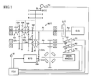
- FIG. 1 schematically shows the configuration of a vehicle which includes a power transmission control apparatus according to the embodiment of the present invention (hereinafter referred to as the "present apparatus").
- This vehicle is a hybrid vehicle which includes an internal combustion engine and a motor generator as power sources, and the present apparatus includes a manual transmission, which does not include a torque converter, and a friction clutch. That is, the present apparatus is the above-described "power transmission control apparatus for an HV-MT vehicle.”
- This vehicle includes an engine E/G, a manual transmission M/T, a friction clutch C/T, and a motor generator M/G.
- the engine E/G is a well known internal combustion engine, such as a gasoline engine which uses gasoline as fuel, or a diesel engine which uses light oil as fuel.
- the manual transmission MIT is a transmission which does not include a torque converter and whose gear position is selected in accordance with the shift position of a shift lever SL operated by a driver.
- the manual transmission MIT has an input shaft Ai for receiving power from an output shaft Ae of the engine E/G, and an output shaft Ao for outputting power to drive wheels of the vehicle.
- the friction clutch C/T is disposed between the output shaft Ae of the engine E/G and the input shaft Ai of the manual transmission M/T.
- the friction clutch C/T is a well known clutch configured such that the engagement state of a friction plate (more specifically, the axial position of a friction plate, which rotates together with the input shaft Ai, in relation to a fry-wheel, which rotates together with the output shaft Ae) changes in accordance with an operation quantity (depression amount) of a clutch pedal CP operated by the driver.
- the engagement state of the friction clutch C/T (the axial position of the friction plate) may be mechanically adjusted in accordance with the operation quantity of the clutch pedal CP, by making use of a link mechanism or the like which mechanically connects the clutch pedal CP to the friction clutch C/T (the friction plate).
- the engagement state of the friction clutch C/T may be electrically adjusted by making use of drive force of an actuator which operates in accordance with the operation quantity of the clutch pedal CP detected by a sensor (a sensor P1 to be described later) (by a so-called by-wire scheme).
- the motor generator M/G has a well known structure (e.g., an AC synchronous motor), and its rotor (not illustrated) rotates together with its output shaft Am.
- EG torque drive torque from the output shaft Ae of the engine E/G
- MG torque drive torque from the output shaft Am of the motor generator M/G
- a sleeve S1 moves from a neutral position shown in FIG. 1 to the right side (a 1-st gear position), whereby an idle gear G1o is fixed to an output shaft Ao such that the idle gear G1o cannot rotate in relation to the output shaft Ao.
- a power transmission system having a speed reduction ratio for the "1-st gear” is established between the output shaft Am of the motor generator M/G and the output shaft Ao of the manual transmission MIT via a gear G1i and the gear G1o. Meanwhile, no power transmission system is established between the input shaft Ai of the manual transmission M/T and the output shaft Ao of the manual transmission M/T.
- a sleeve S2 moves from the neutral position shown in FIG. 1 to the right side (left side) (a 3-rd gear (4-th gear) position), whereby an idle gear G3i (G4i) is fixed to the input shaft Ai such that the idle gear G3i (G4i) cannot rotate in relation to the input shaft Ai.
- a power transmission system having a speed reduction ratio for the "3-rd gear (4-th gear)" is established between the input shaft Ai of the manual transmission M/T (that is, the output shaft Ae of the engine E/G) and the output shaft Ao of the manual transmission M/T via the gear G3i (G4i) and a gear G3o (G4o).
- no power transmission system is established between the output shaft Am of the motor generator M/G and the output shaft Ao of the manual transmission M/T. That is, the "3-rd gear (4-th gear)" is also the "EG travel gear position.”
- a sleeve S3 moves from the neutral position shown in FIG. 1 to the right side (a 5-th gear position), whereby an idle gear G5i is fixed to the input shaft Ai such that the idle gear G5i cannot rotate in relation to the input shaft Ai.
- a power transmission system having a speed reduction ratio for the "5-th gear” is established between the input shaft Ai of the manual transmission M/T (that is, the output shaft Ae of the engine E/G) and the output shaft Ao of the manual transmission M/T via the gear G5i and a gear G5o.
- no power transmission system is established between the output shaft Am of the motor generator M/G and the output shaft Ao of the manual transmission M/T. That is, the "5-rd gear” is also the "EG travel gear position.”
- each of the "2-nd gear” to the "5-th gear” is the EG travel gear position.
- the speed reduction ratios (the speed reduction ratio of the output shaft Ao to the input shaft Ai; that is, the ratio of the rotational speed of the input shaft Ai to that of the output shaft Ao) of the "2-nd gear” to the "5-th gear” are determined such that the speed reduction ratio of the "2-nd gear” is the largest, and that of the "5-th gear” is the smallest.
- the speed reduction ratio of the "1-st gear” (the speed reduction ratio of the output shaft Ao to the output shaft Am; that is, the ratio of the rotational speed of the output shaft Am to that of the output shaft Ao) is greater than the speed reduction ratio of the "2-nd gear.”
- the speed reduction ratio of the "2-nd gear” is greater than the speed reduction ratio of the "2-nd gear.”
- the positions of the sleeves S1 to S3 may be mechanically adjusted in accordance with the shift position of the shift lever SL through use of a link mechanism or the like which mechanically connects the shift lever SL to the sleeves S1 to S3.
- the positions of the sleeves S1 to S3 may be electrically adjusted by making use of drive forces of actuators which operate in accordance with the shift position of the shift lever SL detected by a sensor (a sensor P4 to be described later) (by a so-called by-wire scheme).
- the present apparatus includes the clutch operation quantity sensor P1 which detects the operation quantity (depression amount, clutch stroke, etc.) of the clutch pedal CP, a brake operation quantity sensor P2 which detects the operation quantity (depression force, presence/absence of operation, etc.) of a brake pedal BP, an accelerator operation quantity sensor P3 which detects the operation quantity (accelerator opening) of an accelerator pedal AP, and the shift position sensor P4 which detects the position of the shift lever SL.
- the clutch operation quantity sensor P1 which detects the operation quantity (depression amount, clutch stroke, etc.) of the clutch pedal CP
- a brake operation quantity sensor P2 which detects the operation quantity (depression force, presence/absence of operation, etc.) of a brake pedal BP
- an accelerator operation quantity sensor P3 which detects the operation quantity (accelerator opening) of an accelerator pedal AP
- the shift position sensor P4 which detects the position of the shift lever SL.
- the present apparatus includes an electronic control unit (hereinafter simply referred to as the "ECU").
- the ECU controls the EG torque by controlling the fuel injection amount of the engine E/G (opening of its throttle valve) and controls the MG torque by controlling an inverter (not shown).
- the control of the engine E/G by the present apparatus is generally performed as follows.
- the engine E/G is maintained in a stop state (a state in which fuel injection is not performed).
- the shift lever SL is shifted from the neutral position to one EG travel gear position (any of the "2-nd gear” to "the 5-th gear") (that is, one EG travel gear position is selected) when the engine E/G is in the stop state, the engine E/G is started (fuel injection is started).
- the EG torque is controlled on the basis of the accelerator opening, etc.
- this control will be referred to as "ordinary control of the engine E/G.” Travel in the EG travel gear position is performed through the ordinary control of the engine E/G.
- the shift lever SL is shifted from the neutral position to the EV travel gear position (the "1-st gear") (that is, the EV travel gear position is selected) in a period during which the engine E/G is operating or when the vehicle is stopped, the engine E/G is again maintained in the stop state.
- the control of the motor generator M/G by the present apparatus is generally performed as follows.
- the shift lever SL is shifted from the neutral position to the EV travel gear position (the "1-st gear") (that is, the EV travel gear position is selected) when the motor generator M/G is in the stop state
- "normal start control" which utilizes the MG torque is started.
- the MG torque is controlled on the basis of the accelerator opening and the clutch stroke.
- the MG torque in the normal start control is determined through use of a map or like which is prepared in advance and which defines the relation between "the accelerator opening and the clutch stroke” and “the torque of the internal combustion engine transmitted to the input shaft of the manual transmission via the clutch” at the time when an "ordinary vehicle which includes a manual transmission and a friction clutch and which includes only an internal combustion engine as a power source" starts in the "1-st gear.”
- the EV travel gear position is provided for starting the vehicle through EV travel as in the case of the vehicle of the present embodiment
- a driver shifts the shift lever from the neutral position to the EV travel gear position (the "1-st gear") in a state in which the internal combustion engine E/G is stopped.
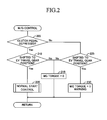
- step 205 the ECU determines whether or not the clutch pedal CP has been depressed. This determination can be made, for example, by determining whether or not the depression amount (clutch stroke) of the clutch pedal CP is equal to or greater than a predetermined value.
- step 210 determines in step 210 whether or not the shift lever SL has been shifted from the neutral position to the EV travel gear position (the "1-st gear”). In the case where the ECU makes a "No” determination, the ECU maintains the MG torque at "0" in step 215. Meanwhile, in the case where the ECU makes a "Yes” determination in step 210; that is, the case where the EV travel gear position (the "1-st gear”) has been selected in a state in which the clutch pedal CP is determined to have been depressed, in step 220, the ECU executes the "normal start control" in which the above-described MG torque is utilized.
- step 225 the ECU determines in step 225 whether or not the shift lever SL has been shifted from the neutral position to the EV travel gear position (the "1-st gear”). In the case where the ECU makes a "No” determination, the ECU maintains the MG torque at "0" in step 215.
- the ECU in the case where the ECU makes a "Yes" determination in step 225; that is, the case where the EV travel gear position (the "1-st gear") has been selected in a state in which the clutch pedal CP is determined not to have been depressed, in step 230, the ECU maintains the MG torque at "0" instead of executing the "normal start control" in which the above-described MG torque is utilized.
- the ECU provides a warning to the driver of the vehicle through utilization of a warning device W (see FIG. 1 ).
- the warning device W may be a buzzer, a lamp, a display in an instrument panel, etc.
- the driver selects the EV travel gear position (the "1-st gear") without depressing the clutch pedal CP
- the MG torque is maintained at "0" even when the accelerator pedal AP is depressed. Therefore, the vehicle cannot start. Furthermore, a warning is provided. Thus, the driver is prompted to operate the clutch pedal CP. In other words, it is possible to prompt the driver to again shift the shift lever from the neutral position to the EV travel gear position (the "1-st gear”) in a state in which he or she has depressed the clutch pedal CP.
- the driver becomes unlikely to acquire the habit of operating the shift lever without depressing the clutch pedal CP when he or she starts the vehicle.
- the power transmission control apparatus employs a structure which can establish a power transmission system between the output shafts Am and Ao in a state in which one of the "2-nd gear” to the "5-th gear," which are EG travel gear positions, is selected, it is possible to make up for insufficiency of the EG torque by use of the MG torque.
- the MG torque is maintained at "0.”
- the embodiment may be modified to adjust the MG toque to a torque (> 0) smaller than the torque determined in the above-described "normal start control.”
- the MG torque whose magnitude corresponds to the accelerator opening cannot be obtained at the time when the vehicle is started through EV travel. Accordingly, it is possible to prompt the driver to operate the clutch pedal CP.
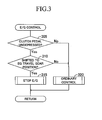
- the above-described embodiment assumes the situation where the driver selects the EV travel gear position (the "1-st gear") without depressing the clutch pedal CP. However, there may occur a situation where the driver selects an EG travel gear position (any of the "2-nd gear” to the "5-th gear") without depressing the clutch pedal CP. In view of this, the ECU may perform the processing shown in FIG. 3 .
- the ECU maintains the engine E/G in the stop state instead of executing the above-described "ordinary control of E/G" (step 315).
- the driver is prompted to operate the clutch pedal CP.
- the driver is prompted to again move the shift lever from the neutral position to the EG travel gear position (any of the "2-nd gear” to the "5-th gear") in a state in which he or she has depressed the clutch pedal CP.
- the expression “maintains the engine E/G in the stop state” in step 315 refers to an operation of preventing the engine E/G from being started despite the fact that the condition for starting the engine E/G is satisfied when the shift lever is shifted to an E/G travel gear position in a state in which the E/G is stopped, for example, when the shift lever is shifted from the EV travel gear position (the "1-st gear") to an EG travel gear position (the "2-nd gear” or the like). That is, in the case where the driver shifts the shift lever from the "1-st gear” to the "2-nd gear” in a state in which he or she has depressed the clutch pedal CP, the engine E/G is started. Meanwhile, in the case where the driver shifts the shift lever from the "1-st gear” to the "2-nd gear” in a state in which he or she has not depressed the clutch pedal CP, the engine E/G is not started.
- the expression “maintains the engine E/G in the stop state” in step 315 refers to an operation of forcedly stopping the engine E/G in a state in which the engine E/G is operating, for example, when the shift lever is shifted from one EG travel gear position (any of the "2-nd gear” to the "5-th gear") to another EG travel gear position (any of the "2-nd gear” to the “5-th gear”). That is, in the case where the driver shifts the shift lever from the "2-nd gear” to the "3-rd gear” in a state in which he or she has depressed the clutch pedal CP, the operation of the engine E/G is maintained. Meanwhile, in the case where the driver shifts the shift lever from the "2-nd gear” to the "3-rd gear” in a state in which he or she has not depressed the clutch pedal CP, the engine E/G is forcedly stopped.
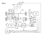
- each of the "1-st gear” and the “2-nd gear” may be the EV travel gear position
- each of the "3-rd gear” to the "5-th gear” may be the EG travel gear position.
Landscapes
- Engineering & Computer Science (AREA)
- Mechanical Engineering (AREA)
- Transportation (AREA)
- Chemical & Material Sciences (AREA)
- Combustion & Propulsion (AREA)
- Power Engineering (AREA)
- Automation & Control Theory (AREA)
- General Engineering & Computer Science (AREA)
- Hybrid Electric Vehicles (AREA)
- Electric Propulsion And Braking For Vehicles (AREA)
- Control Of Vehicle Engines Or Engines For Specific Uses (AREA)
Applications Claiming Priority (2)
| Application Number | Priority Date | Filing Date | Title |
|---|---|---|---|
| JP2010281112A JP5769956B2 (ja) | 2010-12-17 | 2010-12-17 | 車両の動力伝達制御装置 |
| PCT/JP2011/075256 WO2012081324A1 (fr) | 2010-12-17 | 2011-11-02 | Dispositif de commande de transmission de puissance pour véhicule |
Publications (2)
| Publication Number | Publication Date |
|---|---|
| EP2653364A1 true EP2653364A1 (fr) | 2013-10-23 |
| EP2653364A4 EP2653364A4 (fr) | 2016-04-27 |
Family
ID=46244437
Family Applications (1)
| Application Number | Title | Priority Date | Filing Date |
|---|---|---|---|
| EP11848936.8A Withdrawn EP2653364A4 (fr) | 2010-12-17 | 2011-11-02 | Dispositif de commande de transmission de puissance pour véhicule |
Country Status (4)
| Country | Link |
|---|---|
| EP (1) | EP2653364A4 (fr) |
| JP (1) | JP5769956B2 (fr) |
| CN (1) | CN103298672B (fr) |
| WO (1) | WO2012081324A1 (fr) |
Cited By (4)
| Publication number | Priority date | Publication date | Assignee | Title |
|---|---|---|---|---|
| EP2682646A4 (fr) * | 2011-03-01 | 2014-08-20 | Aisin Ai Co Ltd | Transmission manuelle |
| EP2716934A4 (fr) * | 2011-05-25 | 2015-06-17 | Aisin Ai Co Ltd | Boîte de vitesses manuelle |
| US10668801B2 (en) | 2014-11-17 | 2020-06-02 | Alpraaz Ab | Powertrain for a vehicle |
| DE102021001317A1 (de) | 2021-03-11 | 2022-09-15 | Mercedes-Benz Group AG | Hybridantriebssystem für ein Kraftfahrzeug |
Families Citing this family (3)
| Publication number | Priority date | Publication date | Assignee | Title |
|---|---|---|---|---|
| CN104514878B (zh) * | 2014-12-24 | 2017-03-15 | 潍柴动力股份有限公司 | 一种车辆换挡控制方法及tcu |
| JP6187497B2 (ja) * | 2015-02-18 | 2017-08-30 | トヨタ自動車株式会社 | 車両の制御装置、および、車両 |
| JP7363711B2 (ja) * | 2020-08-07 | 2023-10-18 | トヨタ自動車株式会社 | 電気自動車 |
Family Cites Families (10)
| Publication number | Priority date | Publication date | Assignee | Title |
|---|---|---|---|---|
| EP1759915A3 (fr) * | 1998-07-21 | 2007-03-14 | TOKYO R&D CO., LTD. | Véhicule hybride et procédé de gestion du déplacement du véhicule |
| JP2000224710A (ja) | 1999-01-27 | 2000-08-11 | Mitsubishi Motors Corp | ハイブリッド車 |
| WO2007102762A1 (fr) * | 2006-03-09 | 2007-09-13 | Volvo Technology Corporation | Groupe motopropulseur hybride |
| DE102007024363A1 (de) * | 2007-05-24 | 2008-11-27 | Zf Friedrichshafen Ag | Verfahren zur Steuerung eines Antriebsstrangs eines Kraftfahrzeugs |
| JP5151704B2 (ja) * | 2008-06-05 | 2013-02-27 | マツダ株式会社 | 車両の駆動制御装置及び方法 |
| JP5151707B2 (ja) * | 2008-06-09 | 2013-02-27 | マツダ株式会社 | 車両の駆動制御装置及び方法 |
| JP5189524B2 (ja) * | 2009-02-19 | 2013-04-24 | トヨタ自動車株式会社 | 車両用動力伝達装置の制御装置 |
| JP5298960B2 (ja) * | 2009-03-04 | 2013-09-25 | トヨタ自動車株式会社 | ハイブリッド車両の制御装置 |
| JP5267303B2 (ja) * | 2009-04-22 | 2013-08-21 | トヨタ自動車株式会社 | 車両用駆動装置 |
| GB2469864A (en) * | 2009-05-01 | 2010-11-03 | Ford Global Tech Llc | Hybrid vehicle and control method |
-
2010
- 2010-12-17 JP JP2010281112A patent/JP5769956B2/ja not_active Expired - Fee Related
-
2011
- 2011-11-02 CN CN201180064611.7A patent/CN103298672B/zh not_active Expired - Fee Related
- 2011-11-02 WO PCT/JP2011/075256 patent/WO2012081324A1/fr not_active Ceased
- 2011-11-02 EP EP11848936.8A patent/EP2653364A4/fr not_active Withdrawn
Cited By (7)
| Publication number | Priority date | Publication date | Assignee | Title |
|---|---|---|---|---|
| EP2682646A4 (fr) * | 2011-03-01 | 2014-08-20 | Aisin Ai Co Ltd | Transmission manuelle |
| EP2716934A4 (fr) * | 2011-05-25 | 2015-06-17 | Aisin Ai Co Ltd | Boîte de vitesses manuelle |
| US9267573B2 (en) | 2011-05-25 | 2016-02-23 | Aisin Ai Co., Ltd. | Manual transmission |
| US10668801B2 (en) | 2014-11-17 | 2020-06-02 | Alpraaz Ab | Powertrain for a vehicle |
| US11046168B2 (en) | 2014-11-17 | 2021-06-29 | Alpraaz Ab | Powertrain for a vehicle |
| DE102021001317A1 (de) | 2021-03-11 | 2022-09-15 | Mercedes-Benz Group AG | Hybridantriebssystem für ein Kraftfahrzeug |
| DE102021001317B4 (de) | 2021-03-11 | 2024-07-04 | Mercedes-Benz Group AG | Hybridantriebssystem für ein Kraftfahrzeug |
Also Published As
| Publication number | Publication date |
|---|---|
| WO2012081324A1 (fr) | 2012-06-21 |
| CN103298672B (zh) | 2016-01-06 |
| EP2653364A4 (fr) | 2016-04-27 |
| JP5769956B2 (ja) | 2015-08-26 |
| CN103298672A (zh) | 2013-09-11 |
| JP2012126318A (ja) | 2012-07-05 |
Similar Documents
| Publication | Publication Date | Title |
|---|---|---|
| US8712622B2 (en) | Power transmission control device for vehicle | |
| JP5521151B2 (ja) | 車両の動力伝達制御装置 | |
| EP2653363B1 (fr) | Dispositif de commande de transmission de puissance pour véhicule | |
| US8727940B2 (en) | Device for controlling power transmission of vehicle | |
| EP2653364A1 (fr) | Dispositif de commande de transmission de puissance pour véhicule | |
| US8725336B2 (en) | Power transmission control device for vehicle | |
| US20140083247A1 (en) | Manual transmission | |
| EP2548780A2 (fr) | Dispositif de commande de transmission de puissance pour véhicule | |
| US8758194B2 (en) | Power transmission control device for vehicle | |
| JP5715848B2 (ja) | 車両の動力伝達制御装置 | |
| JP2012121433A (ja) | 車両の動力伝達制御装置 | |
| JP2011220135A (ja) | 車両の制御装置 | |
| JP2012126317A (ja) | 車両の動力伝達制御装置 | |
| JP2008120378A (ja) | 車両の走行制御装置 | |
| WO2012077382A1 (fr) | Dispositif de commande de transmission de puissance de véhicule | |
| JP5650262B2 (ja) | 車両の動力伝達制御装置 |
Legal Events
| Date | Code | Title | Description |
|---|---|---|---|
| PUAI | Public reference made under article 153(3) epc to a published international application that has entered the european phase |
Free format text: ORIGINAL CODE: 0009012 |
|
| 17P | Request for examination filed |
Effective date: 20130625 |
|
| AK | Designated contracting states |
Kind code of ref document: A1 Designated state(s): AL AT BE BG CH CY CZ DE DK EE ES FI FR GB GR HR HU IE IS IT LI LT LU LV MC MK MT NL NO PL PT RO RS SE SI SK SM TR |
|
| DAX | Request for extension of the european patent (deleted) | ||
| RAP1 | Party data changed (applicant data changed or rights of an application transferred) |
Owner name: AISIN AI CO., LTD. |
|
| RA4 | Supplementary search report drawn up and despatched (corrected) |
Effective date: 20160331 |
|
| RIC1 | Information provided on ipc code assigned before grant |
Ipc: B60W 10/02 20060101ALI20160323BHEP Ipc: B60L 11/14 20060101ALI20160323BHEP Ipc: F02D 29/02 20060101ALI20160323BHEP Ipc: B60K 6/48 20071001ALI20160323BHEP Ipc: B60W 10/08 20060101ALI20160323BHEP Ipc: B60W 10/10 20120101ALI20160323BHEP Ipc: B60W 10/06 20060101ALI20160323BHEP Ipc: B60K 6/547 20071001ALI20160323BHEP Ipc: B60W 20/00 20160101AFI20160323BHEP |
|
| GRAP | Despatch of communication of intention to grant a patent |
Free format text: ORIGINAL CODE: EPIDOSNIGR1 |
|
| INTG | Intention to grant announced |
Effective date: 20180507 |
|
| STAA | Information on the status of an ep patent application or granted ep patent |
Free format text: STATUS: THE APPLICATION IS DEEMED TO BE WITHDRAWN |
|
| RIC1 | Information provided on ipc code assigned before grant |
Ipc: B60L 11/14 20060101ALI20160323BHEP Ipc: B60W 10/06 20060101ALI20160323BHEP Ipc: B60W 10/10 20120101ALI20160323BHEP Ipc: B60W 10/08 20060101ALI20160323BHEP Ipc: F02D 29/02 20060101ALI20160323BHEP Ipc: B60W 20/00 20160101AFI20160323BHEP Ipc: B60W 10/02 20060101ALI20160323BHEP Ipc: B60K 6/547 20071001ALI20160323BHEP Ipc: B60K 6/48 20071001ALI20160323BHEP |
|
| 18D | Application deemed to be withdrawn |
Effective date: 20180918 |