EP2653381A2 - Système d'actionnement de pas de pale d'hélice améliorée - Google Patents
Système d'actionnement de pas de pale d'hélice améliorée Download PDFInfo
- Publication number
- EP2653381A2 EP2653381A2 EP13163302.6A EP13163302A EP2653381A2 EP 2653381 A2 EP2653381 A2 EP 2653381A2 EP 13163302 A EP13163302 A EP 13163302A EP 2653381 A2 EP2653381 A2 EP 2653381A2
- Authority
- EP
- European Patent Office
- Prior art keywords
- drain line
- pcm
- valve
- blade pitch
- aircraft
- Prior art date
- Legal status (The legal status is an assumption and is not a legal conclusion. Google has not performed a legal analysis and makes no representation as to the accuracy of the status listed.)
- Granted
Links
Images


Classifications
-
- B—PERFORMING OPERATIONS; TRANSPORTING
- B64—AIRCRAFT; AVIATION; COSMONAUTICS
- B64C—AEROPLANES; HELICOPTERS
- B64C11/00—Propellers, e.g. of ducted type; Features common to propellers and rotors for rotorcraft
- B64C11/30—Blade pitch-changing mechanisms
- B64C11/38—Blade pitch-changing mechanisms fluid, e.g. hydraulic
Definitions
- the present invention relates to a propeller blade pitch actuation system.
- the invention relates to increasing a pressure force available for changing the pitch of a propeller blade.
- Propeller driven aircraft typically include a system for adjusting the pitch of each propeller blade.
- Blade pitch generally ranges from a fine pitch position, where the blade has a low level of attack, to a coarse pitch position, where the blade has a high angle of attack.
- the fine pitch position the blade moves relatively little air with each rotation, permitting operation when little forward thrust is desired.
- the blade pitch becomes coarser, moving more air with each rotation.
- Increased engine power and gears between the engine and the propeller provide the increased torque necessary to keep the propeller moving at a desired speed as the blade pitch becomes coarser.
- the extreme coarse pitch position, or feathered position the blade is pitched in the direction of flight to minimize propeller drag in the event of engine failure.
- the blade is pitched past the fine pitch position to a negative angle of attack to produce reverse thrust.
- Reverse thrust may be employed to slow the aircraft once it has landed. In either forward or reverse thrust conditions, as the blade pitch moves away from a fine pitch position, increasingly greater force is required to adjust the blade pitch.
- blade pitch changes are driven by a propeller actuator connected by a trunnion pin to each blade.
- the propeller actuator is a translating piston which moves when a pressure force, in the form of a hydraulic pressure difference, is applied to the piston.
- the translation of the piston is transmitted through the trunnion pin to the blade which rotates on a bearing assembly.
- Providing a pressure force sufficient to move the blade pitch to full coarse and full reverse positions under desired operating conditions often requires a high-pressure hydraulic pump to provide the necessary hydraulic pressure.
- a propeller actuator, hydraulic lines and fittings must be strong enough to withstand the hydraulic pressure. Increasing the pressure force by increasing the hydraulic pressure requires increasingly heavy or expensive pumps, pressure actuators, lines, and fittings.
- the present invention is a propeller blade pitch actuation system including a propeller control module (PCM), a PCM drain line, a first drain line, a drain line restriction, a second drain line, and a valve.
- the PCM adjusts blade pitch on at least one propeller blade.
- the PCM drain line is connected to the PCM to drain hydraulic fluid employed in adjusting the propeller blade pitch.
- the first drain line is downstream of the PCM drain line and the drain line restriction is downstream of the first drain line.
- the second drain line is downstream of the PCM drain line.
- the valve includes a first valve position and a second valve position. The first valve position connects the PCM drain line to the first drain line and the second valve position connects the PCM drain line to the second drain line. Hydraulic pressure of the first drain line between the valve and the drain line restriction is greater than hydraulic pressure of the second drain line.
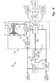
- FIG. 1 is a schematic representation of a powerplant lubrication and blade pitch actuation system embodying the present invention.
- FIG. 2 is a schematic representation of another embodiment of a powerplant lubrication and blade pitch actuation system of the present invention.
- FIG. 3 is a schematic representation of another embodiment of a powerplant lubrication and blade pitch actuation system of the present invention.
- FIG. 4 is a schematic representation of another embodiment of a powerplant lubrication and blade pitch actuation system of the present invention.
- a propeller actuator is controlled by a propeller control module (PCM), which supplies hydraulic fluid from a high-pressure pump to a chamber on one side of the propeller actuator piston while draining hydraulic fluid from a chamber on the other side of the piston.
- PCM propeller control module
- a combination of the pressure difference between the two chambers and differential areas of the chambers results in the hydraulic pressure force that moves the piston, thus changing blade pitch.
- the pressure difference between the chambers is limited by the hydraulic pressure available from the high-pressure pump and the hydraulic pressure in the PCM drain line.
- hydraulic fluid in the PCM drain line flows to other components and is employed by those components. The use of the hydraulic fluid by those components restricts the flow of hydraulic fluid in the drain line downstream from the PCM drain line. Back pressure from such drain line restrictions downstream from the PCM drain line increase the hydraulic pressure in the PCM drain line, reducing the hydraulic pressure force available to move the piston.
- the present invention is a propeller blade pitch actuation system employing a valve to selectively connect a PCM drain line to either a drain line having a drain line restriction or, under conditions where a larger pressure force is required by the PCM, to a lower pressure drain line not having the drain line restriction.
- the ability to switch to a lower pressure drain line under conditions calling for a greater hydraulic pressure force to move the propeller actuator piston permits the use of lighter or less expensive pumps, pressure actuators, lines, and fittings.
- bypassing the drain line restriction to provide increased pressure force is employed only when the aircraft is on the ground, such as when full reverse is desired, and when bypassing the drain line restriction for such a short time is not detrimental to the operation or longevity of the aircraft.
- FIG. 1 is a schematic representation of a powerplant lubrication and blade pitch actuation system embodying the present invention.
- FIG. 1 illustrates a portion of powerplant lubrication and blade pitch actuation system 110 including hydraulic pump 12, scavenge sump 14, and propeller blade pitch actuation system 120.
- Propeller blade pitch actuation system 120 includes high pressure pump 22, propeller control module (PCM) 24, PCM drain line 26, coarse pitch hydraulic line 28, fine pitch hydraulic line 30, propeller actuator 32, first drain line 140, second drain line 42, valve 44, and drain line restriction 150.
- Propeller actuator 32 includes propeller actuator piston 34, coarse pitch hydraulic chamber 36, and fine pitch hydraulic chamber 38.
- hydraulic pump 12 is connected by hydraulic lines on one side to high-pressure pump 22 and to a propeller gear box (not shown).
- High-pressure pump 22 is connected to PCM 24.
- PCM 24 is connected to valve 44 by way of PCM drain line 26.
- PCM 24 is also connected to propeller actuator 32 at coarse pitch hydraulic chamber 36 by coarse pitch hydraulic line 28 and at fine pitch hydraulic chamber 38 by fine pitch hydraulic line 30.
- Propeller actuator piston 34 is within propeller actuator 32, bounded on one end by coarse pitch hydraulic chamber 36 and on an opposite end by fine pitch hydraulic chamber 38.
- Propeller actuator piston 34 is also connected to a blade (not shown) by way of a trunnion (not shown), as discussed above.
- Valve 44 is connected to a first drain line 140 and second drain line 42.
- First drain line 140 is connected to drain line restriction 150. Drain line restriction 150 and second drain line 42 both connect to scavenge sump 14, as does a return hydraulic line from the propeller gear box. Scavenge sump 14 is connected to hydraulic pump 12 to complete a hydraulic circulation loop.
- hydraulic pump 12 pumps hydraulic fluid from scavenge sump 14 to high-pressure pump 22, as well as to the propeller gear box for lubrication of the gear box.
- High-pressure pump 22 increases the pressure of the hydraulic fluid for use by PCM 24.
- PCM 24 selectively connects the pressurized hydraulic fluid from high-pressure pump 22 to one of either coarse pitch hydraulic line 28 or fine pitch hydraulic line 30 and connects PCM drain line 26 to the other one of coarse pitch hydraulic line 28 or fine pitch hydraulic line 30, depending on the desired blade pitch change direction.
- PCM 24 connects the pressurized hydraulic fluid from high-pressure pump 22 to fine pitch hydraulic line 30, pressurizing fine pitch hydraulic chamber 38.
- PCM 24 connects coarse pitch hydraulic line 28 to PCM drain line 26, reducing the pressure within coarse pitch hydraulic chamber 36 to that of PCM drain line 26.
- the pressure and area differences between the two chambers creates a hydraulic pressure force that causes propeller actuator piston 34 to move in fine pitch direction Df as hydraulic fluid fills an expanding fine pitch hydraulic chamber 38 and drains from a shrinking coarse pitch hydraulic chamber 36.
- PCM 24 connects the pressurized hydraulic fluid from high-pressure pump 22 to coarse pitch hydraulic line 28, pressurizing coarse pitch hydraulic chamber 36.
- PCM 24 connects fine pitch hydraulic line 30 to PCM drain line 26, reducing the pressure within fine pitch hydraulic chamber 38 to that of PCM drain line 26.
- valve 44 Hydraulic fluid in PCM drain line 26 flows to valve 44.
- valve 44 is an electromechanical valve, such as a solenoid valve, and is electrically selectable to be in one of two valve positions: a first valve position and a second valve position.
- first valve position hydraulic fluid flows from PCM drain line 26, through valve 44, into first drain line 140 to drain line restriction 150.
- Drain line restriction 150 employs the hydraulic fluid from first drain line 140 to perform a function generally useful during operation of the aircraft, particularly when in flight. However, to perform this function, drain line restriction 150 necessarily creates a back pressure in PCM drain line 26, increasing the hydraulic pressure in PCM drain line 26.
- PCM drain line 26 reduces the pressure difference between fine pitch hydraulic chamber 38 and coarse pitch hydraulic chamber 36, reducing the hydraulic pressure force available to move propeller actuator piston 34 and change the propeller blade pitch. From drain line restriction 150, hydraulic fluid flows to scavenge sump 14 where it is available once again to hydraulic pump 12.
- valve 44 may be directed to bypass drain line restriction 150 to provide increased pressure force only when the increased pressure force is necessary for a limited time and when bypassing drain line restriction 150 for the limited time is not detrimental to the operation or longevity of the aircraft.
- the surface area of propeller actuator piston 34 bounding coarse pitch hydraulic chamber 36 is significantly larger than the surface area of propeller actuator piston 34 bounding fine pitch hydraulic chamber 38.
- This piston area asymmetry works well during normal flight conditions and conditions where forward thrust is desired by effectively reducing the pressure high-pressure pump 22 must produce to move propeller actuator piston 34 in coarse pitch direction Dc.
- this area imbalance makes it more difficult to move the blade past the fine pitch position to a negative pitch position required to produce full reverse thrust.
- Embodiments of the present invention solve this problem by selecting the second valve position of valve 44 when reverse thrust is required.
- PCM drain line 26 By connecting PCM drain line 26 to second drain line 42, the hydraulic pressure force available to move propeller actuator piston 34 is increased enough to move the blade to the negative pitch position required to produce full reverse thrust.
- a pressure force is provided that is sufficient to move the blade pitch throughout its range under desired operating conditions without resorting to heavier or more expensive components.
- valve 44 may switch from the first valve position to the second valve position in response to a signal indicating the aircraft is not in flight.
- valve 44 is electrically connected to weight on wheels sensor 60, throttle position sensor 62 and Electronic Engine Control (EEC) or Full Authority Digital Engine Control (FADEC) 66.
- Airspeed sensor 64 is electrically connected to EEC or FADEC 66, as are weight on wheels sensor 60 and throttle position 62.
- Weight on wheels sensor 60 detects weight on at least one aircraft landing gear wheel and produces a corresponding electrical signal.
- Throttle position sensor 62 detects a position of an engine throttle indicating a reverse throttle selection and produces a corresponding electrical signal.
- Airspeed sensor 64 measures airspeed and produces a corresponding electrical signal.
- EEC or FADEC 66 is an electronic control system that receives cockpit commands in the form of a signal indicative of a performance level required from an engine, in addition to signals from a variety of sensors and other systems around the engine and the aircraft.
- EEC or FADEC 66 applies a set of control rules to the received signals and determines control signals to send to systems on and around the engine, including valve 44 and PCM 24 (electrical connection to PCM 24 not shown).
- weight on wheels sensor 60 upon landing, weight on wheels sensor 60 detects weight on at least one aircraft landing gear wheel, producing an electrical signal. Weight on wheels sensor 60 may send an electrical signal to valve 44 directly to switch valve 44 from the first valve position to the second valve position, providing the increased pressure force necessary to move the blade to full reverse thrust.
- throttle position sensor 62 may instead be employed to signal valve 44 directly once a reverse throttle position is detected.
- EEC or FACED 66 may determine, based on the signal from airspeed sensor 64 indicating that measured airspeed is below an airspeed necessary for the aircraft to be in flight, that the aircraft has landed and reverse thrust is required. Then EEC or FADEC 66 sends an electrical signal to valve 44 causing it to switch to the second valve position to provide the increased pressure force necessary for full reverse thrust. Alternatively, EEC or FADEC 66 may send an electrical signal to valve 44 based on electrical signals from weight on wheels sensor 60, throttle position sensor 62, or airspeed sensor 64 or any combination of these sensors. It is further understood that, although valve 44 is illustrated as an electromechanical valve, the present invention encompasses embodiments in which the valve is signaled by other means, including pneumatic, hydraulic, or mechanical means.
- FIG. 2 is a schematic representation of another embodiment of a powerplant lubrication and blade pitch actuation system of the present invention.
- the embodiment of FIG. 2 is like the embodiment of FIG. 1 , except that in propeller blade pitch actuation system 220 of powerplant lubrication and blade pitch actuation system 210, the drain line restriction is auxiliary tank 250.
- Auxiliary tank 250 is connected to PCM 24 by auxiliary feather pump 252.
- Auxiliary tank 250 is a tank for storing hydraulic fluid to be employed by PCM 24 in the event of a failure of a supply of hydraulic fluid to propeller blade pitch actuation system 220.
- auxiliary tank 250 stores just enough hydraulic fluid for PCM 24, by way of auxiliary feather pump 252, to provide the pressure force necessary for feathering the propeller blades.
- auxiliary tank 250 employs the hydraulic fluid from first drain line 240 to perform a function generally useful during operation of the aircraft - providing a reservoir of hydraulic fluid sufficient to feather the propeller in the event of engine failure. This function is generally only of critical importance when the aircraft is in flight.
- valve 44 may be directed to bypass auxiliary tank 250 to provide increased pressure force for reverse thrust while landing.
- the increased pressure force is necessary for a limited time (while landing) and bypassing auxiliary tank 250 while landing is not detrimental to the operation or longevity of the aircraft.
- FIG. 3 is a schematic representation of another embodiment of a powerplant lubrication and blade pitch actuation system of the present invention.
- the embodiment of FIG. 3 is like the embodiment of FIG. 1 , except that in powerplant lubrication and blade pitch actuation system 310, the drain line restriction is heat exchanger 350.
- Heat exchanger 350 employs the hydraulic fluid from first drain line 340 to perform a function generally useful during operation of the aircraft - transferring heat between the hydraulic fluid employed in PCM 24 to another fluid stream.
- the hydraulic fluid may absorb heat from mechanical components (e.g. the gear box, hydraulic pump 12, high-pressure pump 22, etc.) and need to be cooled by transferring heat to a cooling airstream.
- the heat of the hydraulic fluid may be employed in heat exchanger 350 to preheat fuel for the aircraft engine.
- This function is generally only of critical importance when the aircraft is in flight.
- valve 44 may be directed to bypass heat exchanger 350 to provide increased pressure force for reverse thrust while landing. During landing, the increased pressure force is necessary for a limited time (while landing) and bypassing heat exchanger 350 for a limited time is not detrimental to the operation or longevity of the aircraft.
- FIG. 4 is a schematic representation of another embodiment of a powerplant lubrication and blade pitch actuation system of the present invention.
- the embodiment of FIG. 4 is like the embodiment of FIG. 1 , except that in powerplant lubrication and blade pitch actuation system 410, the drain line restriction is orifice 450.
- Orifice 450 is part of lubrication system 470, which also includes lubrication jets 472.
- Lubrication system 470 employs the hydraulic fluid from first drain line 440 to perform a function generally useful during operation of the aircraft - lubricating mechanical components (e.g. the gear box).
- Orifice 450 produces back pressure sufficient for lubrication jets 472 to spray the hydraulic fluid (also employed as a lubricant) on the mechanical components.
- valve 44 may be directed to bypass lubrication system 470 and orifice 450 to provide increased pressure force for reverse thrust while landing.
- the increased pressure force is necessary for a limited time (while landing) and bypassing lubrication system 470 and orifice 450 for a limited time is not detrimental to the operation or longevity of the aircraft.
- a propeller blade pitch actuation system is provided with a greater hydraulic pressure force by employing a valve to selectively connect a propeller control module drain line to either a drain line having a drain line restriction or, under conditions where a larger pressure force is required by the propeller control module, to a lower-pressure drain line without the drain line restriction.
- Making a greater hydraulic pressure force available to move a propeller actuator piston in this way eliminates the need for heavier or more expensive pumps, pressure actuators, lines, and fittings that would otherwise be required.
- bypassing the drain line restriction to provide increased pressure force is employed when the aircraft is on the ground when full reverse is desired and when bypassing the drain line restriction for such a short time is not detrimental to the operation or longevity of the aircraft.
Landscapes
- Engineering & Computer Science (AREA)
- Aviation & Aerospace Engineering (AREA)
- Fluid-Pressure Circuits (AREA)
- Wind Motors (AREA)
- General Details Of Gearings (AREA)
- Valve Device For Special Equipments (AREA)
Applications Claiming Priority (1)
| Application Number | Priority Date | Filing Date | Title |
|---|---|---|---|
| US13/449,483 US9120559B2 (en) | 2012-04-18 | 2012-04-18 | Propeller blade pitch actuation system |
Publications (3)
| Publication Number | Publication Date |
|---|---|
| EP2653381A2 true EP2653381A2 (fr) | 2013-10-23 |
| EP2653381A3 EP2653381A3 (fr) | 2015-06-03 |
| EP2653381B1 EP2653381B1 (fr) | 2017-03-08 |
Family
ID=48139727
Family Applications (1)
| Application Number | Title | Priority Date | Filing Date |
|---|---|---|---|
| EP13163302.6A Active EP2653381B1 (fr) | 2012-04-18 | 2013-04-11 | Système d'actionnement de pas de pale d'hélice améliorée |
Country Status (3)
| Country | Link |
|---|---|
| US (1) | US9120559B2 (fr) |
| EP (1) | EP2653381B1 (fr) |
| ES (1) | ES2619452T3 (fr) |
Cited By (1)
| Publication number | Priority date | Publication date | Assignee | Title |
|---|---|---|---|---|
| CN110803277A (zh) * | 2018-08-06 | 2020-02-18 | 普拉特 - 惠特尼加拿大公司 | 可变桨距螺旋桨控制系统 |
Families Citing this family (14)
| Publication number | Priority date | Publication date | Assignee | Title |
|---|---|---|---|---|
| US10464668B2 (en) | 2015-09-02 | 2019-11-05 | Jetoptera, Inc. | Configuration for vertical take-off and landing system for aerial vehicles |
| EP4306789A3 (fr) | 2015-09-02 | 2024-06-12 | Jetoptera, Inc. | Système propulsif fluidique |
| US11001378B2 (en) | 2016-08-08 | 2021-05-11 | Jetoptera, Inc. | Configuration for vertical take-off and landing system for aerial vehicles |
| US10683082B2 (en) * | 2016-04-29 | 2020-06-16 | Ratier-Figeac Sas | Hydraulic actuation systems |
| US10501169B2 (en) * | 2016-06-17 | 2019-12-10 | Pratt & Whitney Canada Corp. | Propeller blade angle control system |
| US10472050B2 (en) | 2016-08-31 | 2019-11-12 | Honeywell International Inc. | Propeller pitch control actuation system |
| CA3068569A1 (fr) | 2017-06-27 | 2019-01-03 | Jetoptera, Inc. | Configuration pour systeme de decollage et d'atterrissage vertical pour vehicules aeriens |
| US10864980B2 (en) * | 2018-07-10 | 2020-12-15 | Pratt & Whitney Canada Corp. | System and method for feathering an aircraft propeller |
| US10899433B2 (en) * | 2018-07-10 | 2021-01-26 | Pratt & Whitney Canada Corp. | System and method for feathering an aircraft propeller |
| US10807701B2 (en) | 2019-02-08 | 2020-10-20 | Honeywell International Inc. | Aircraft turboprop engine propeller pitch control system including a controllable feather valve |
| US11414175B2 (en) | 2019-04-01 | 2022-08-16 | Pratt & Whitney Canada Corp. | Method and system for operating an aircraft powerplant |
| US11530027B2 (en) * | 2019-12-02 | 2022-12-20 | Pratt & Whitney Canada Corp. | Propeller control unit with bypass drain line |
| IT202300000423A1 (it) | 2023-01-13 | 2024-07-13 | Ge Avio Srl | Sistema di bloccaggio del passo |
| US12060812B1 (en) | 2023-03-16 | 2024-08-13 | General Electric Company | Turbo engine having blade pitch actuation system for variable pitch fan |
Family Cites Families (10)
| Publication number | Priority date | Publication date | Assignee | Title |
|---|---|---|---|---|
| US3067825A (en) | 1956-12-18 | 1962-12-11 | Dowty Rotol Ltd | Coarse pitch conduit valve and operator for hydraulic variable pitch propellers |
| US5213471A (en) * | 1990-09-04 | 1993-05-25 | General Electric Company | Propeller pitch control |
| US6077040A (en) | 1998-05-01 | 2000-06-20 | United Technologies Corporation | Control system for blades for a variable pitch propeller |
| US6019717A (en) * | 1998-08-19 | 2000-02-01 | Fleetguard, Inc. | Nozzle inlet enhancement for a high speed turbine-driven centrifuge |
| WO2002053880A2 (fr) * | 2001-01-05 | 2002-07-11 | Ingersoll-Rand Company | Systeme de soupapes hydrauliques |
| US6422816B1 (en) | 2001-05-21 | 2002-07-23 | Hamilton Sundstrand Corporation | Variable pitch propeller control system |
| US6811376B2 (en) | 2002-03-19 | 2004-11-02 | Hamilton Sundstrand | Actuation system for a controllable pitch propeller |
| US7118336B2 (en) | 2003-12-19 | 2006-10-10 | Pratt & Whitney Canada Corp. | Pressurized oil supply for propeller engine system |
| US7172391B2 (en) | 2004-08-03 | 2007-02-06 | Hamilton Sundstrand | Propeller actuation system |
| US7976279B2 (en) | 2007-06-11 | 2011-07-12 | Hamilton Sundstrand Corporation | Blade pitch actuation mechanism |
-
2012
- 2012-04-18 US US13/449,483 patent/US9120559B2/en active Active
-
2013
- 2013-04-11 EP EP13163302.6A patent/EP2653381B1/fr active Active
- 2013-04-11 ES ES13163302.6T patent/ES2619452T3/es active Active
Non-Patent Citations (1)
| Title |
|---|
| None |
Cited By (1)
| Publication number | Priority date | Publication date | Assignee | Title |
|---|---|---|---|---|
| CN110803277A (zh) * | 2018-08-06 | 2020-02-18 | 普拉特 - 惠特尼加拿大公司 | 可变桨距螺旋桨控制系统 |
Also Published As
| Publication number | Publication date |
|---|---|
| EP2653381A3 (fr) | 2015-06-03 |
| ES2619452T3 (es) | 2017-06-26 |
| EP2653381B1 (fr) | 2017-03-08 |
| US9120559B2 (en) | 2015-09-01 |
| US20130280065A1 (en) | 2013-10-24 |
Similar Documents
| Publication | Publication Date | Title |
|---|---|---|
| US9120559B2 (en) | Propeller blade pitch actuation system | |
| US7118336B2 (en) | Pressurized oil supply for propeller engine system | |
| EP3712058B1 (fr) | Soupape de commande combinée de survitesse, de mise en drapeau et de déclenchement inverse pour un ensemble d'hélice | |
| US12486811B2 (en) | Propeller assembly and pitch control unit | |
| CN109305330B (zh) | 用于飞行器的螺旋桨控制系统 | |
| US9718536B2 (en) | Counter-rotating open-rotor (CROR) | |
| US8651812B2 (en) | Machine such as a gas turbine engine | |
| CN111225851A (zh) | 螺旋桨控制单元 | |
| JP4312158B2 (ja) | 補強型飛行制御面作動システムおよび方法 | |
| EP2192307A2 (fr) | Système de commande de pas de pale | |
| EP3378763B1 (fr) | Systèmes hydrauliques d'aéronef possédant des composants partagés | |
| EP1623921B1 (fr) | Système d'actionnement d'hélices | |
| US8075271B2 (en) | Electrohydraulic propeller governor | |
| US20090099750A1 (en) | Manuever-based aircraft gas turbine engine speed control system and method | |
| US20250290425A1 (en) | Electronically piloted low pitch stop protection | |
| CA3262214A1 (fr) | Protection de butée petit pas pilotée électroniquement | |
| Jacazio et al. | A Robust Adaptive Hydraulic Power Generation System for Jet Engines | |
| Jacazio et al. | Robust and Adaptive Power Generation, Control and Actuation System for Air Flow Control of Jet Engines |
Legal Events
| Date | Code | Title | Description |
|---|---|---|---|
| PUAI | Public reference made under article 153(3) epc to a published international application that has entered the european phase |
Free format text: ORIGINAL CODE: 0009012 |
|
| AK | Designated contracting states |
Kind code of ref document: A2 Designated state(s): AL AT BE BG CH CY CZ DE DK EE ES FI FR GB GR HR HU IE IS IT LI LT LU LV MC MK MT NL NO PL PT RO RS SE SI SK SM TR |
|
| AX | Request for extension of the european patent |
Extension state: BA ME |
|
| PUAL | Search report despatched |
Free format text: ORIGINAL CODE: 0009013 |
|
| AK | Designated contracting states |
Kind code of ref document: A3 Designated state(s): AL AT BE BG CH CY CZ DE DK EE ES FI FR GB GR HR HU IE IS IT LI LT LU LV MC MK MT NL NO PL PT RO RS SE SI SK SM TR |
|
| AX | Request for extension of the european patent |
Extension state: BA ME |
|
| RIC1 | Information provided on ipc code assigned before grant |
Ipc: B64C 11/38 20060101AFI20150424BHEP |
|
| 17P | Request for examination filed |
Effective date: 20151203 |
|
| RBV | Designated contracting states (corrected) |
Designated state(s): AL AT BE BG CH CY CZ DE DK EE ES FI FR GB GR HR HU IE IS IT LI LT LU LV MC MK MT NL NO PL PT RO RS SE SI SK SM TR |
|
| GRAP | Despatch of communication of intention to grant a patent |
Free format text: ORIGINAL CODE: EPIDOSNIGR1 |
|
| INTG | Intention to grant announced |
Effective date: 20160919 |
|
| GRAS | Grant fee paid |
Free format text: ORIGINAL CODE: EPIDOSNIGR3 |
|
| GRAA | (expected) grant |
Free format text: ORIGINAL CODE: 0009210 |
|
| AK | Designated contracting states |
Kind code of ref document: B1 Designated state(s): AL AT BE BG CH CY CZ DE DK EE ES FI FR GB GR HR HU IE IS IT LI LT LU LV MC MK MT NL NO PL PT RO RS SE SI SK SM TR |
|
| REG | Reference to a national code |
Ref country code: GB Ref legal event code: FG4D |
|
| REG | Reference to a national code |
Ref country code: CH Ref legal event code: EP Ref country code: AT Ref legal event code: REF Ref document number: 873263 Country of ref document: AT Kind code of ref document: T Effective date: 20170315 |
|
| REG | Reference to a national code |
Ref country code: FR Ref legal event code: PLFP Year of fee payment: 5 |
|
| REG | Reference to a national code |
Ref country code: IE Ref legal event code: FG4D |
|
| REG | Reference to a national code |
Ref country code: DE Ref legal event code: R096 Ref document number: 602013018192 Country of ref document: DE |
|
| REG | Reference to a national code |
Ref country code: ES Ref legal event code: FG2A Ref document number: 2619452 Country of ref document: ES Kind code of ref document: T3 Effective date: 20170626 |
|
| REG | Reference to a national code |
Ref country code: LT Ref legal event code: MG4D |
|
| REG | Reference to a national code |
Ref country code: NL Ref legal event code: MP Effective date: 20170308 |
|
| PG25 | Lapsed in a contracting state [announced via postgrant information from national office to epo] |
Ref country code: LT Free format text: LAPSE BECAUSE OF FAILURE TO SUBMIT A TRANSLATION OF THE DESCRIPTION OR TO PAY THE FEE WITHIN THE PRESCRIBED TIME-LIMIT Effective date: 20170308 Ref country code: FI Free format text: LAPSE BECAUSE OF FAILURE TO SUBMIT A TRANSLATION OF THE DESCRIPTION OR TO PAY THE FEE WITHIN THE PRESCRIBED TIME-LIMIT Effective date: 20170308 Ref country code: GR Free format text: LAPSE BECAUSE OF FAILURE TO SUBMIT A TRANSLATION OF THE DESCRIPTION OR TO PAY THE FEE WITHIN THE PRESCRIBED TIME-LIMIT Effective date: 20170609 Ref country code: HR Free format text: LAPSE BECAUSE OF FAILURE TO SUBMIT A TRANSLATION OF THE DESCRIPTION OR TO PAY THE FEE WITHIN THE PRESCRIBED TIME-LIMIT Effective date: 20170308 Ref country code: NO Free format text: LAPSE BECAUSE OF FAILURE TO SUBMIT A TRANSLATION OF THE DESCRIPTION OR TO PAY THE FEE WITHIN THE PRESCRIBED TIME-LIMIT Effective date: 20170608 |
|
| REG | Reference to a national code |
Ref country code: AT Ref legal event code: MK05 Ref document number: 873263 Country of ref document: AT Kind code of ref document: T Effective date: 20170308 |
|
| PG25 | Lapsed in a contracting state [announced via postgrant information from national office to epo] |
Ref country code: SE Free format text: LAPSE BECAUSE OF FAILURE TO SUBMIT A TRANSLATION OF THE DESCRIPTION OR TO PAY THE FEE WITHIN THE PRESCRIBED TIME-LIMIT Effective date: 20170308 Ref country code: RS Free format text: LAPSE BECAUSE OF FAILURE TO SUBMIT A TRANSLATION OF THE DESCRIPTION OR TO PAY THE FEE WITHIN THE PRESCRIBED TIME-LIMIT Effective date: 20170308 Ref country code: BG Free format text: LAPSE BECAUSE OF FAILURE TO SUBMIT A TRANSLATION OF THE DESCRIPTION OR TO PAY THE FEE WITHIN THE PRESCRIBED TIME-LIMIT Effective date: 20170608 Ref country code: LV Free format text: LAPSE BECAUSE OF FAILURE TO SUBMIT A TRANSLATION OF THE DESCRIPTION OR TO PAY THE FEE WITHIN THE PRESCRIBED TIME-LIMIT Effective date: 20170308 |
|
| PG25 | Lapsed in a contracting state [announced via postgrant information from national office to epo] |
Ref country code: NL Free format text: LAPSE BECAUSE OF FAILURE TO SUBMIT A TRANSLATION OF THE DESCRIPTION OR TO PAY THE FEE WITHIN THE PRESCRIBED TIME-LIMIT Effective date: 20170308 |
|
| PG25 | Lapsed in a contracting state [announced via postgrant information from national office to epo] |
Ref country code: SK Free format text: LAPSE BECAUSE OF FAILURE TO SUBMIT A TRANSLATION OF THE DESCRIPTION OR TO PAY THE FEE WITHIN THE PRESCRIBED TIME-LIMIT Effective date: 20170308 Ref country code: AT Free format text: LAPSE BECAUSE OF FAILURE TO SUBMIT A TRANSLATION OF THE DESCRIPTION OR TO PAY THE FEE WITHIN THE PRESCRIBED TIME-LIMIT Effective date: 20170308 Ref country code: RO Free format text: LAPSE BECAUSE OF FAILURE TO SUBMIT A TRANSLATION OF THE DESCRIPTION OR TO PAY THE FEE WITHIN THE PRESCRIBED TIME-LIMIT Effective date: 20170308 Ref country code: CZ Free format text: LAPSE BECAUSE OF FAILURE TO SUBMIT A TRANSLATION OF THE DESCRIPTION OR TO PAY THE FEE WITHIN THE PRESCRIBED TIME-LIMIT Effective date: 20170308 Ref country code: EE Free format text: LAPSE BECAUSE OF FAILURE TO SUBMIT A TRANSLATION OF THE DESCRIPTION OR TO PAY THE FEE WITHIN THE PRESCRIBED TIME-LIMIT Effective date: 20170308 |
|
| PG25 | Lapsed in a contracting state [announced via postgrant information from national office to epo] |
Ref country code: PT Free format text: LAPSE BECAUSE OF FAILURE TO SUBMIT A TRANSLATION OF THE DESCRIPTION OR TO PAY THE FEE WITHIN THE PRESCRIBED TIME-LIMIT Effective date: 20170710 Ref country code: SM Free format text: LAPSE BECAUSE OF FAILURE TO SUBMIT A TRANSLATION OF THE DESCRIPTION OR TO PAY THE FEE WITHIN THE PRESCRIBED TIME-LIMIT Effective date: 20170308 Ref country code: IS Free format text: LAPSE BECAUSE OF FAILURE TO SUBMIT A TRANSLATION OF THE DESCRIPTION OR TO PAY THE FEE WITHIN THE PRESCRIBED TIME-LIMIT Effective date: 20170708 Ref country code: PL Free format text: LAPSE BECAUSE OF FAILURE TO SUBMIT A TRANSLATION OF THE DESCRIPTION OR TO PAY THE FEE WITHIN THE PRESCRIBED TIME-LIMIT Effective date: 20170308 |
|
| REG | Reference to a national code |
Ref country code: CH Ref legal event code: PL |
|
| REG | Reference to a national code |
Ref country code: DE Ref legal event code: R097 Ref document number: 602013018192 Country of ref document: DE |
|
| PLBE | No opposition filed within time limit |
Free format text: ORIGINAL CODE: 0009261 |
|
| STAA | Information on the status of an ep patent application or granted ep patent |
Free format text: STATUS: NO OPPOSITION FILED WITHIN TIME LIMIT |
|
| REG | Reference to a national code |
Ref country code: IE Ref legal event code: MM4A |
|
| PG25 | Lapsed in a contracting state [announced via postgrant information from national office to epo] |
Ref country code: DK Free format text: LAPSE BECAUSE OF FAILURE TO SUBMIT A TRANSLATION OF THE DESCRIPTION OR TO PAY THE FEE WITHIN THE PRESCRIBED TIME-LIMIT Effective date: 20170308 Ref country code: MC Free format text: LAPSE BECAUSE OF FAILURE TO SUBMIT A TRANSLATION OF THE DESCRIPTION OR TO PAY THE FEE WITHIN THE PRESCRIBED TIME-LIMIT Effective date: 20170308 |
|
| 26N | No opposition filed |
Effective date: 20171211 |
|
| PG25 | Lapsed in a contracting state [announced via postgrant information from national office to epo] |
Ref country code: SI Free format text: LAPSE BECAUSE OF FAILURE TO SUBMIT A TRANSLATION OF THE DESCRIPTION OR TO PAY THE FEE WITHIN THE PRESCRIBED TIME-LIMIT Effective date: 20170308 Ref country code: LU Free format text: LAPSE BECAUSE OF NON-PAYMENT OF DUE FEES Effective date: 20170411 Ref country code: LI Free format text: LAPSE BECAUSE OF NON-PAYMENT OF DUE FEES Effective date: 20170430 Ref country code: CH Free format text: LAPSE BECAUSE OF NON-PAYMENT OF DUE FEES Effective date: 20170430 |
|
| REG | Reference to a national code |
Ref country code: BE Ref legal event code: MM Effective date: 20170430 |
|
| REG | Reference to a national code |
Ref country code: FR Ref legal event code: PLFP Year of fee payment: 6 |
|
| PG25 | Lapsed in a contracting state [announced via postgrant information from national office to epo] |
Ref country code: IE Free format text: LAPSE BECAUSE OF NON-PAYMENT OF DUE FEES Effective date: 20170411 |
|
| PG25 | Lapsed in a contracting state [announced via postgrant information from national office to epo] |
Ref country code: BE Free format text: LAPSE BECAUSE OF NON-PAYMENT OF DUE FEES Effective date: 20170430 |
|
| PG25 | Lapsed in a contracting state [announced via postgrant information from national office to epo] |
Ref country code: MT Free format text: LAPSE BECAUSE OF NON-PAYMENT OF DUE FEES Effective date: 20170411 |
|
| PG25 | Lapsed in a contracting state [announced via postgrant information from national office to epo] |
Ref country code: HU Free format text: LAPSE BECAUSE OF FAILURE TO SUBMIT A TRANSLATION OF THE DESCRIPTION OR TO PAY THE FEE WITHIN THE PRESCRIBED TIME-LIMIT; INVALID AB INITIO Effective date: 20130411 |
|
| PG25 | Lapsed in a contracting state [announced via postgrant information from national office to epo] |
Ref country code: CY Free format text: LAPSE BECAUSE OF NON-PAYMENT OF DUE FEES Effective date: 20170308 |
|
| PG25 | Lapsed in a contracting state [announced via postgrant information from national office to epo] |
Ref country code: MK Free format text: LAPSE BECAUSE OF FAILURE TO SUBMIT A TRANSLATION OF THE DESCRIPTION OR TO PAY THE FEE WITHIN THE PRESCRIBED TIME-LIMIT Effective date: 20170308 |
|
| PG25 | Lapsed in a contracting state [announced via postgrant information from national office to epo] |
Ref country code: TR Free format text: LAPSE BECAUSE OF FAILURE TO SUBMIT A TRANSLATION OF THE DESCRIPTION OR TO PAY THE FEE WITHIN THE PRESCRIBED TIME-LIMIT Effective date: 20170308 |
|
| PG25 | Lapsed in a contracting state [announced via postgrant information from national office to epo] |
Ref country code: AL Free format text: LAPSE BECAUSE OF FAILURE TO SUBMIT A TRANSLATION OF THE DESCRIPTION OR TO PAY THE FEE WITHIN THE PRESCRIBED TIME-LIMIT Effective date: 20170308 |
|
| REG | Reference to a national code |
Ref country code: DE Ref legal event code: R082 Ref document number: 602013018192 Country of ref document: DE |
|
| P01 | Opt-out of the competence of the unified patent court (upc) registered |
Effective date: 20230522 |
|
| PGFP | Annual fee paid to national office [announced via postgrant information from national office to epo] |
Ref country code: DE Payment date: 20250319 Year of fee payment: 13 |
|
| PGFP | Annual fee paid to national office [announced via postgrant information from national office to epo] |
Ref country code: ES Payment date: 20250502 Year of fee payment: 13 |
|
| PGFP | Annual fee paid to national office [announced via postgrant information from national office to epo] |
Ref country code: GB Payment date: 20260319 Year of fee payment: 14 |
|
| PGFP | Annual fee paid to national office [announced via postgrant information from national office to epo] |
Ref country code: IT Payment date: 20260319 Year of fee payment: 14 |
|
| PGFP | Annual fee paid to national office [announced via postgrant information from national office to epo] |
Ref country code: FR Payment date: 20260320 Year of fee payment: 14 |