EP2653611A1 - Weichenzungenrollervorrichtung und hiermit ausgestattete Weiche - Google Patents
Weichenzungenrollervorrichtung und hiermit ausgestattete Weiche Download PDFInfo
- Publication number
- EP2653611A1 EP2653611A1 EP13163953.6A EP13163953A EP2653611A1 EP 2653611 A1 EP2653611 A1 EP 2653611A1 EP 13163953 A EP13163953 A EP 13163953A EP 2653611 A1 EP2653611 A1 EP 2653611A1
- Authority
- EP
- European Patent Office
- Prior art keywords
- connecting bracket
- switch blade
- blade roller
- roller
- roller holder
- Prior art date
- Legal status (The legal status is an assumption and is not a legal conclusion. Google has not performed a legal analysis and makes no representation as to the accuracy of the status listed.)
- Withdrawn
Links
- 241001669679 Eleotris Species 0.000 claims description 4
- 238000006073 displacement reaction Methods 0.000 claims description 4
- 230000007704 transition Effects 0.000 claims description 4
- 238000012423 maintenance Methods 0.000 description 6
- 230000008901 benefit Effects 0.000 description 2
- 238000000034 method Methods 0.000 description 2
- 230000008569 process Effects 0.000 description 2
- 238000013461 design Methods 0.000 description 1
- 238000012986 modification Methods 0.000 description 1
- 230000004048 modification Effects 0.000 description 1
- 230000000737 periodic effect Effects 0.000 description 1
- 230000008707 rearrangement Effects 0.000 description 1
- 230000000717 retained effect Effects 0.000 description 1
- 210000002105 tongue Anatomy 0.000 description 1
- 238000012549 training Methods 0.000 description 1
Images




Classifications
-
- E—FIXED CONSTRUCTIONS
- E01—CONSTRUCTION OF ROADS, RAILWAYS, OR BRIDGES
- E01B—PERMANENT WAY; PERMANENT-WAY TOOLS; MACHINES FOR MAKING RAILWAYS OF ALL KINDS
- E01B7/00—Switches; Crossings
- E01B7/02—Tongues; Associated constructions
-
- E—FIXED CONSTRUCTIONS
- E01—CONSTRUCTION OF ROADS, RAILWAYS, OR BRIDGES
- E01B—PERMANENT WAY; PERMANENT-WAY TOOLS; MACHINES FOR MAKING RAILWAYS OF ALL KINDS
- E01B2202/00—Characteristics of moving parts of rail systems, e.g. switches, special frogs, tongues
- E01B2202/04—Nature of the support or bearing
- E01B2202/044—Rolling
- E01B2202/046—Rolling with rolls on fixed part
Definitions
- the invention relates to a switch blade roller device and a turnout provided therewith.
- Rail-bound traffic makes use of turnouts in order to guide a rail-bound vehicle such as a train or tram onto or off a chosen rail route. It is known to apply slide chairs with a switch blade roller at such turnouts.
- the switch rail in an operative position, wherein it lies against the stock rail, rests on the slide chair. In a rest position, wherein the switch rail lies at a position remote from the stock rail, the switch rail is supported by a switch blade roller.
- a great advantage of applying slide chairs with a switch blade roller is that relatively small switching forces of the switch machine are required without the slide chairs having to be lubricated.
- Switch blade roller devices have to be set after being arranged on a turnout. It is important here that the setting takes place in a correct manner in order to guarantee a reliable operation of the turnout. There is therefore a need for a switch blade roller device which can be set in simple and correct manner.
- Periodic turnout maintenance comprises of rearranging the ballast so that the turnout is once again supported in stable and flat manner by the ballast bed.
- Switch blade roller devices arranged between sleepers can be damaged during this rearranging of the ballast.
- An object of the present invention is to provide a switch blade roller device wherein said drawbacks do not occur, or at least do so to lesser extent.
- switch blade roller device comprising:
- Such a switch blade roller device can be arranged on and removed from sleepers of a turnout with simple means so that the switch blade roller device can be temporarily removed in simple manner for the purpose of rearranging the ballast supporting a turnout. The risk of damage to the switch blade roller device due to this rearrangement is then prevented.
- the rotation shaft of the switch blade roller arranged rotatably in the roller holder is substantially parallel to the longitudinal direction of the connecting bracket, this rotation shaft is also substantially parallel to a (switch) rail of the turnout.
- switch rail When the turnout is operated, the switch rail will displace in transverse direction and roll onto the switch blade roller.
- the switch rail will exert only a limited tilting moment, or no tilting moment, on the connecting bracket of the switch blade roller device. It hereby suffices for the switch blade roller device according to the invention to be arranged with only the two connecting bracket outer ends on or at adjacent sleepers, and one or more additional supporting points adjacently of the connecting bracket are unnecessary.
- the switch blade roller device according to the invention moreover retains its setting relative to the turnout when it is temporarily removed from the turnout for maintenance operations.
- the connecting bracket with roller holder mounted thereon can be temporarily removed here as a whole from the sleepers, after which the turnout maintenance can take place.
- the setting of the switch blade roller device is therefore only necessary before the first use thereof.
- the switch blade roller device can be assembled in a workshop, after which it has only to be placed and set on site before a first use.
- the reliability is greater than that of the switch blade roller devices currently applied in the rail network.
- This increased reliability can be attributed particularly to the smaller number of individual components, as well as the relative simplicity thereof.
- the roller holder With the exception of the roller holder, the other components can be manufactured in relatively simple manner. The most precise processes are moreover focussed on one component: the roller holder.
- the switch blade roller device comprises a single continuous connecting bracket. This has the advantage that the switch blade roller device is removable in one operation from the sleepers of a turnout while the setting thereof is retained.
- the continuous connecting bracket When a switch rail rolls onto the switch blade roller of the switch blade roller device, the continuous connecting bracket will be pressed several millimetres downward and the switch rail will thereby roll gradually onto the switch blade roller. Peak loads are prevented by the connecting bracket being pressed down in this way.
- connecting bracket transition parts which provide a distance between the connecting bracket outer ends and the connecting bracket middle part such that the upper side of a mounted switch blade roller, which is arranged rotatably in the roller holder arranged on the connecting bracket middle part, extends some distance above the connecting bracket outer ends.
- the switch blade roller When mounted on a turnout, the switch blade roller is hereby located at a height level at which it lifts the switch rail relative to the slide chair when the switch rail is situated in a rest position remote from the stock rail.
- the switch blade roller device comprises setting means which are arranged at a higher level than the connecting bracket middle part and directly above the surface of the connecting bracket, and which are configured to thereby set the position of the switch blade roller relative to the connecting bracket middle part of the connecting bracket.
- a correct setting is important in guaranteeing safe operation of the turnout.
- the setting means comprise both a height setting and a transverse setting.
- the transverse direction is defined here as transversely of the connecting bracket, and so also transversely of the longitudinal direction of the (switch) rail.
- the roller holder comprises a roller holder base plate and the setting means comprise at least a slot-like recess arranged in the roller holder base plate.
- This slot-like recess enables sliding of the roller holder relative to the connecting bracket middle part of the connecting bracket. After being slid to a desired position, the connection between the connecting bracket and the roller holder is fixed using fixing means, such as a bolt connection.
- the roller holder comprises at least two roller holder flange parts extending transversely from the roller holder base plate and having slot-like recesses arranged therein;
- one or more height-setting parts are arrangeable between the connecting bracket middle part and the roller holder base plate. Arranging one or more height-setting parts makes the height adjustable.
- the height-setting part comprises a substantially flat sole plate.
- Such sole plates can be supplied in different thicknesses. It is also possible to envisage a slot extending as far as an edge being provided which makes it possible to slide in the sole plate without full disassembly being necessary.
- the height-setting part comprises a wedge-shaped sole part.
- the height is adjustable by sliding the wedge shape, wherein it is advantageous that separate sole plates are unnecessary.
- the roller holder base plate has a chamfered form co-acting with the wedge-shaped height setting part, although it is alternatively possible to envisage applying two co-acting chamfered height-setting parts.
- the invention further relates to a turnout, comprising:
- the mounting means comprise a mounting bracket releasably arrangeable on the sleeper.
- the turnout shown in Figure 1 comprises a stock rail 6 and a switch rail 4, wherein in the rest position shown in Figure 1 switch rail 4 lies some distance from stock rail 6. In this rest position shown in Figure 1 switch rail 4 is supported by a switch blade roller 82 of a switch blade roller device 1. Such switch blade roller devices 1 are arranged at the locations shown with circles in Figure 1 .
- FIG. 2 The top view of Figure 2 shows how such a switch blade roller device 1 is arranged between two sleepers 10 of a turnout.
- Switch rail 4 is shown with broken lines in Figure 2 and is in a rest position, wherein switch rail 4 is in a position remote from stock rail 6 and is supported by switch blade roller 82. In an operative position, wherein switch rail 4 would lie against stock rail 6, it would be supported by slide chair 8 of switch blade roller device 1.
- Switch blade roller 82 is accommodated in a roller holder 44 ( Figure 2 ).
- This roller holder 44 comprises a roller holder base plate 46 with slot-like recesses 50 therein.
- Roller holder 44 can be arranged on the connecting bracket middle part 30 of connecting bracket 24 and the position of switch blade roller 82 relative to connecting bracket 24 is adjustable using the slot-like recess 50.
- Connecting bracket 24 comprises connecting bracket outer ends 26 which can be arranged on sleepers 10 and a connecting bracket middle part 30 present between the connecting bracket outer ends 26.
- the connecting bracket outer ends 26 are arranged releasably on a sleeper 10 using a mounting bracket 12.
- connecting bracket transition parts 28 Situated between the connecting bracket outer ends 26 and the connecting bracket middle part 30 are connecting bracket transition parts 28 which ensure that the connecting bracket middle part 30 lies a distance under the connecting bracket outer ends 26 such that there is sufficient overall height for placing a roller holder 44 with switch blade roller 82 arranged therein.
- switch blade roller 82 extends some distance above the connecting bracket outer ends 26 so that it lifts switch rail 4 off slide chair 8 when switch rail 4 is situated in the rest position remote from stock rail 6.
- the position of the switch blade roller device between the sleepers protects the switch blade roller device to some extent from weather influences such as snow, rainwater or other fouling.
- Mounting brackets 12 comprise a strip part 14 having therein a receiving part 16 provided with protrusions 18 for receiving a connecting bracket outer end 26 therebetween.
- Mounting brackets 20 are provided on strip part 14 of mounting bracket 12 .
- Setting means are provided to enable setting of switch blade roller 82 at a desired position relative to the connecting bracket middle part 30 of connecting bracket 24.
- the setting means comprise a combination of a bolt 72, a first locking ring 74, a second locking ring 76 and an elastically deformable clamping ring 78 which can be pressed against a roughened part 58 of a roller holder flange part 48 of roller holder 44.
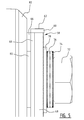
- the shaft 80 with switch blade roller 82 arranged rotatably thereon is adjustable in the height in the manner which will be further elucidated below with reference to Figures 7 and 8 .
- roller holder base plate 46 of roller holder 44 also comprises a roughened part 56 close to slot-like recess 50.
- a bolt 34, first and second locking rings 38, 40 and a clamping ring 42 are provided to thereby enable setting and fixing of the horizontal position of roller holder 44 relative to connecting bracket 24.
- Bolt 34 protrudes here through the hole 32 drilled in the connecting bracket middle part 30 and engages on the underside thereof on a nut 36.
- a height-setting part 64 consisting of a U-shaped profile part 64 with a rear wall 66 and side walls 68 provided with slot-like recesses 70. These side walls 68 of profile part 64 are arranged slidably along roller holder flange parts 48.
- a cover strip 60 is provided if desired on the upper side of roller holder flange parts 48 to prevent a height displacement of the U-shaped profile part 64.
- Cover strips 60 function here as stop edge for the upper edge of side walls 68 of height-setting part 64.
- the shaft 80 on which switch blade roller 82 is arranged extends through the opening where slot-like recesses 54 of the roller holder flange parts 48 coincide with the slot-like recesses 70 of side walls 68 of profile part 64. Because the slot-like recesses 70 in profile part 64 are lie at an angle relative to slot-like recesses 54 arranged in the roller holder flange parts 48, the height of switch blade roller 82 is adjustable via a displacement of profile part 64 relative to roller holder 44.
- switch blade roller 82 Once the height setting of switch blade roller 82 has been set as desired, this position is fixed by tightening the bolt 72 via locking rings 74, 76 and clamping ring 78. Switch blade roller 82 is arranged rotatably around shaft 80 in roller holder 44 over bearings 84.
- the height setting of switch blade roller 82 is further elucidated in Figures 7 and 8 .
- the shaft 80 on which switch blade roller 82 is rotatably arranged protrudes through the coinciding recess of slot 54 in the roller holder flange part 48 and slot 70 in side wall 68 of height-setting part 64. Because the slot-like recess 70 in profile part 64 is arranged at an angle relative to the slot-like recess 54 present in the roller holder flange part 48, the coinciding opening between the two slot-like recesses 54, 70 shifts in height direction when height-setting part 64 is moved laterally over the roller holder base plate 46 of roller holder 44.
- shaft 80 is in a first situation and in Figure 8 this shaft 80 is in a second, raised situation relative to the first situation shown in Figure 7 . Because shaft 80 is displaced in height direction, the switch blade roller 82 arranged rotatably around shaft 80 is also displaced in height direction.
- Figures 9 and 10 show alternative embodiments wherein the height setting of roller holder 44 relative to connecting bracket 24 takes place by arranging one or more height-setting parts 164, 264 between the roller holder base plate 46 and the connecting bracket middle part 30.
- these height-setting parts 164 are flat sole plates, while in the embodiment shown in Figure 10 the height-setting parts 264 have a wedge shape.
- the wedge-shaped height-setting means 264 co-act with a wedge-shaped underside of the roller holder base plate 46 of roller holder 44 or with a second wedge-shaped height-setting part (not shown) placeable between a flat roller holder base plate 46 and the wedge-shaped height-setting part 264 shown in Figure 10 .
- FIG. 9 Provided in Figure 9 is a slot-like recess through which shaft 80 fits and in which it is supported.
- a locking ring 92 clamped with nut 86 prevents the shaft 80 with switch blade roller 82 being able to displace upward out of slot-like recess 154 in the mounted state.
- roller holder 80 is arranged in a slot-like recess 254, after which it can be locked with a locking pin (not shown) through locking recesses 90.
Landscapes
- Engineering & Computer Science (AREA)
- Mechanical Engineering (AREA)
- Architecture (AREA)
- Civil Engineering (AREA)
- Structural Engineering (AREA)
- Railway Tracks (AREA)
Applications Claiming Priority (1)
| Application Number | Priority Date | Filing Date | Title |
|---|---|---|---|
| NL2008644A NL2008644C2 (nl) | 2012-04-16 | 2012-04-16 | Tongrolinrichting alsmede daarvan voorziene wissel. |
Publications (1)
| Publication Number | Publication Date |
|---|---|
| EP2653611A1 true EP2653611A1 (de) | 2013-10-23 |
Family
ID=48083060
Family Applications (1)
| Application Number | Title | Priority Date | Filing Date |
|---|---|---|---|
| EP13163953.6A Withdrawn EP2653611A1 (de) | 2012-04-16 | 2013-04-16 | Weichenzungenrollervorrichtung und hiermit ausgestattete Weiche |
Country Status (2)
| Country | Link |
|---|---|
| EP (1) | EP2653611A1 (de) |
| NL (1) | NL2008644C2 (de) |
Cited By (2)
| Publication number | Priority date | Publication date | Assignee | Title |
|---|---|---|---|---|
| CN115821659A (zh) * | 2022-12-23 | 2023-03-21 | 中铁山桥集团有限公司 | 一种可减少可动心轨辙叉的心轨转换阻力的装置 |
| US12359377B1 (en) | 2024-04-10 | 2025-07-15 | voestalpine Railway Systems Nortrak LLC | Switch point roller assembly |
Citations (3)
| Publication number | Priority date | Publication date | Assignee | Title |
|---|---|---|---|---|
| AT375697B (de) * | 1982-09-03 | 1984-08-27 | Maurer Gerhard | Rollenlagerung fuer weichenzungen |
| DE9317723U1 (de) * | 1993-11-19 | 1994-01-20 | Enzesfeld-Caro Metallwerke Ag, Enzesfeld | Weiche für Gleise des schienengebundenen Verkehrs |
| DE29913898U1 (de) * | 1999-05-14 | 2000-09-21 | Companhia Vale Do Rio Doce, Minas Gerais | Rollenausbildung zur Verschiebung von Eisenbahn-Weichenschienen |
-
2012
- 2012-04-16 NL NL2008644A patent/NL2008644C2/nl not_active IP Right Cessation
-
2013
- 2013-04-16 EP EP13163953.6A patent/EP2653611A1/de not_active Withdrawn
Patent Citations (3)
| Publication number | Priority date | Publication date | Assignee | Title |
|---|---|---|---|---|
| AT375697B (de) * | 1982-09-03 | 1984-08-27 | Maurer Gerhard | Rollenlagerung fuer weichenzungen |
| DE9317723U1 (de) * | 1993-11-19 | 1994-01-20 | Enzesfeld-Caro Metallwerke Ag, Enzesfeld | Weiche für Gleise des schienengebundenen Verkehrs |
| DE29913898U1 (de) * | 1999-05-14 | 2000-09-21 | Companhia Vale Do Rio Doce, Minas Gerais | Rollenausbildung zur Verschiebung von Eisenbahn-Weichenschienen |
Cited By (2)
| Publication number | Priority date | Publication date | Assignee | Title |
|---|---|---|---|---|
| CN115821659A (zh) * | 2022-12-23 | 2023-03-21 | 中铁山桥集团有限公司 | 一种可减少可动心轨辙叉的心轨转换阻力的装置 |
| US12359377B1 (en) | 2024-04-10 | 2025-07-15 | voestalpine Railway Systems Nortrak LLC | Switch point roller assembly |
Also Published As
| Publication number | Publication date |
|---|---|
| NL2008644C2 (nl) | 2013-10-17 |
Similar Documents
| Publication | Publication Date | Title |
|---|---|---|
| US8602317B2 (en) | Support for a system for fastening a rail and a system for fastening a rail | |
| US8757510B2 (en) | Laterally displaceable rail fastening | |
| US9103073B2 (en) | System for fastening a rail, and fastening of a rail on a substrate | |
| KR100704943B1 (ko) | 궤도 스판 높이 조절용 스크류 장치 | |
| JP5185136B2 (ja) | レールを固定するシステム | |
| IL204527A (en) | A rail reinforcing system and tensile clamps for this type of system | |
| EP2653611A1 (de) | Weichenzungenrollervorrichtung und hiermit ausgestattete Weiche | |
| EA038080B1 (ru) | Устройство крепления рельса и подкладная пластина для такого устройства крепления рельса | |
| EP4182504B1 (de) | Plattenspuranpassungsplatte und installationsverfahren | |
| EP3325717B1 (de) | Vorrichtung zum halten der schienenspurweite für weichen-/kreuzungsabschnitte für eisenbahngleis und verfaren zum halten der schienenspurweite | |
| CA2834013A1 (en) | Rail support assembly with improved shoulder | |
| CA2809062A1 (en) | System for fastening a rail and method for renovating a rail fastening point | |
| DK2851468T3 (en) | Mounting device for a rail | |
| CN1425092A (zh) | 悬轨固定组件 | |
| KR102079295B1 (ko) | 상승방지턱을 가진 분기기용 가드레일 체결장치 | |
| EP2888408B1 (de) | Eisenbahn | |
| CA2351360C (en) | Preloading rail clips in steel sleepers | |
| US7434768B2 (en) | Portable turnout system | |
| WO2018193253A1 (en) | A non-intrusive turnout system for a railway track | |
| KR101653575B1 (ko) | 탈선복구용 유압실린더 지지대 | |
| CN205343048U (zh) | 一种道岔可动心辙叉组装平台 | |
| DE2409510A1 (de) | Schotterloser oberbau | |
| KR102224226B1 (ko) | 철도 분기기의 가드레일 지지용 t블록 및 이를 이용한 목침목 분기기 pc침목화 시공방법 | |
| US1779212A (en) | Combination tie plate | |
| EP1975317A3 (de) | Schienenstreckensystem, Verfahren zur Herstellung sowie Verfahren zur Justierung eines Schienenstreckensystems |
Legal Events
| Date | Code | Title | Description |
|---|---|---|---|
| PUAI | Public reference made under article 153(3) epc to a published international application that has entered the european phase |
Free format text: ORIGINAL CODE: 0009012 |
|
| AK | Designated contracting states |
Kind code of ref document: A1 Designated state(s): AL AT BE BG CH CY CZ DE DK EE ES FI FR GB GR HR HU IE IS IT LI LT LU LV MC MK MT NL NO PL PT RO RS SE SI SK SM TR |
|
| AX | Request for extension of the european patent |
Extension state: BA ME |
|
| STAA | Information on the status of an ep patent application or granted ep patent |
Free format text: STATUS: THE APPLICATION IS DEEMED TO BE WITHDRAWN |
|
| 18D | Application deemed to be withdrawn |
Effective date: 20140424 |