EP2653638B1 - Mécanisme de verrouillage pour boîte à gants - Google Patents
Mécanisme de verrouillage pour boîte à gants Download PDFInfo
- Publication number
- EP2653638B1 EP2653638B1 EP20120164804 EP12164804A EP2653638B1 EP 2653638 B1 EP2653638 B1 EP 2653638B1 EP 20120164804 EP20120164804 EP 20120164804 EP 12164804 A EP12164804 A EP 12164804A EP 2653638 B1 EP2653638 B1 EP 2653638B1
- Authority
- EP
- European Patent Office
- Prior art keywords
- pinion
- lever
- locking mechanism
- bar
- handle
- Prior art date
- Legal status (The legal status is an assumption and is not a legal conclusion. Google has not performed a legal analysis and makes no representation as to the accuracy of the status listed.)
- Active
Links
Images

Classifications
-
- E—FIXED CONSTRUCTIONS
- E05—LOCKS; KEYS; WINDOW OR DOOR FITTINGS; SAFES
- E05B—LOCKS; ACCESSORIES THEREFOR; HANDCUFFS
- E05B83/00—Vehicle locks specially adapted for particular types of wing or vehicle
- E05B83/28—Locks for glove compartments, console boxes, fuel inlet covers or the like
- E05B83/30—Locks for glove compartments, console boxes, fuel inlet covers or the like for glove compartments
-
- E—FIXED CONSTRUCTIONS
- E05—LOCKS; KEYS; WINDOW OR DOOR FITTINGS; SAFES
- E05B—LOCKS; ACCESSORIES THEREFOR; HANDCUFFS
- E05B13/00—Devices preventing the key or the handle or both from being used
- E05B13/10—Devices preventing the key or the handle or both from being used formed by a lock arranged in the handle
- E05B13/101—Devices preventing the key or the handle or both from being used formed by a lock arranged in the handle for disconnecting the handle
-
- E—FIXED CONSTRUCTIONS
- E05—LOCKS; KEYS; WINDOW OR DOOR FITTINGS; SAFES
- E05C—BOLTS OR FASTENING DEVICES FOR WINGS, SPECIALLY FOR DOORS OR WINDOWS
- E05C9/00—Arrangements of simultaneously actuated bolts or other securing devices at well-separated positions on the same wing
- E05C9/04—Arrangements of simultaneously actuated bolts or other securing devices at well-separated positions on the same wing with two sliding bars moved in opposite directions when fastening or unfastening
- E05C9/041—Arrangements of simultaneously actuated bolts or other securing devices at well-separated positions on the same wing with two sliding bars moved in opposite directions when fastening or unfastening with rack and pinion mechanism
Definitions
- the invention relates to a locking mechanism for a glove box of a vehicle.
- Glove boxes for vehicles are known in the prior art. Glove boxes are located in the passenger compartments of vehicles and used to store goods. In order to lock the goods within the glove box, the glove box has a lid. The lid requires a mechanism which ensures that the goods in the glove box cannot fall out unintentionally. For this reason, the lid typically has a latch.
- US 7,036,852 B2 provides a system for operating the rod of a glove box capable of reducing the number of parts by simplifying the structure for operating the rod used in a locking device of the glove box and improving productability by decreasing the size of the installation space.
- EP 2 090 468 A1 provides a locking mechanism for a glove box of a vehicle comprising:
- a locking mechanism for a glove box of a vehicle comprising a vertically operable handle for accessing the glove box, wherein the handle comprises a lever. Further, the mechanism comprises at least two locking rods with pins for engagement of the pins with a counterpart locking recess of the vehicle. Each of the locking rods comprises a rack gear. Further, the mechanism comprises a pinion engaging simultaneously with the rack gears of the locking rods, wherein the pinion comprises a bar attached to the pinion and in contact with the lever, wherein the bar is adapted for converting a vertical movement of the lever into a rotational movement of the pinion.
- the contact region of the lever and the bar is disposed from the rotation axis of the pinion at a distance, wherein the distance is at least the diameter of the pinion.
- Embodiments of the present invention may have the advantage that a vertically operable handle can be combined with a horizontally operating latch mechanism for a glove box with minimized space requirements. Only a single pinion is required and thus the number of required parts for assembly of the locking mechanism is minimized. Further, due to the minimized number of parts, the friction within the individual components is reduced thus easing the operability of the locking mechanism by vertically operating the handle.
- a vehicle is understood as any kind of transportation system including a car, van, pickup, train, ship or plane, which is capable of transporting passengers.
- a glove box is understood as any lockable compartment within the vehicle which is able to store goods.
- the only requirement is that the handle of the glove box is operable by a vertical movement.
- a vertical movement is understood as the main movement direction when operating the handle to open the glove box. This may also comprise a further movement for example away from the glove box lid. In combination, this may thus comprise an elliptic or almost rotational movement of the handle.
- the pinion has two pinion gears located on opposite sides of the pinion, wherein the two pinion gears simultaneously engage directly with the rack gears.
- the lever has a direction of extension from the handle towards the bar, wherein the direction of the extension of the lever and the axis of the pinion are laterally displaced with respect to one another.
- the locking mechanism further comprises a lock cylinder attached to the handle, wherein the lever is attached to the lock cylinder.
- the axis of the lock cylinder and the axis of the pinion are excentric.
- the lever has a direction of extension from the handle towards the bar, wherein the direction of extension of the lever and the axis of the lock cylinder are laterally displaced with respect to one another.
- a first advantage may be that by only a small movement of the handle and thus the lock, a large displacement of the lever is obtained.
- a user of the locking mechanism only has to for example pull the handle and displace it vertically over a rather little distance, whereas nevertheless the pinion is operated smoothly for completely disengaging the pins from the counterpart locking recess of the vehicle.
- a further advantage may be given in case of the embodiment that the lock cylinder, the lever and the bar are arranged in that a rotational movement of the lock cylinder permits enabling or disenabling the contact of the lever and the bar.
- the rotational movement of the lock cylinder permits enabling or disenabling the contact of the lever and the bar.
- both the bar and the lever preferably have corresponding flat surface shapes.
- any other surface shapes are also possible.
- the locking mechanism further comprises a resetting spring for providing a torque force resetting the rotational movement of the pinion.
- the resetting spring comprises a torsion spring or a clock spring.
- the handle itself may also comprise a resetting spring thus forcing the handle back to its original position.
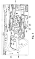
- Fig. 1 schematically illustrates a glove box 100 with a locking mechanism.
- the glove box 100 comprises a lid 122 which can rotate in direction 104 away from the interior space of the glove box upon operation of the locking mechanism.
- the locking mechanism is operated by pulling up the handle 120 in vertical direction 106.
- the pulling of the handle may also comprise a movement component in the direction away from the interior space of the glove box. Due to this pulling of the handle 120, the locking mechanism (not fully visible) in Fig. 1 is operated and the locking rods 114 and 116 are disengaged with their locking pins 118 from respective recesses 110 located in support parts 108 of the vehicle.
- the locking rods 114 and 116 are moved in a horizontal direction, for example the y-direction of the vehicle.
- the y-direction of the vehicle is the lateral direction of the vehicle
- the x-direction is the longitudinal direction of the vehicle
- the z-direction is the direction perpendicular to the x and y-direction, i.e. the vertical direction of the vehicle.
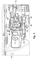
- Fig. 2 shows a perspective view of the locking mechanism in a non-operated stage of the handle 120.
- the handle 120 comprises a lever.
- the locking rods each comprise a respective rack gear 200 (the rack gear 200 of the locking rod 114 is not visible in Fig. 2 ).
- a pinion 204 is engaging simultaneously with the rack gears 200 of the locking rods 114 and 116.
- the pinion 204 comprises a bar 208 attached to the pinion 204 and in contact with the lever 206.
- the bar 208 is adapted for converting a vertical movement of the lever 206 into direction 212 into a rotational movement of the pinion 204.
- the pinion 204 has two pinion gears 202 located on opposite sides of the pinion 204. These two pinion gears 202 engage simultaneously and directly with the respective rack gears 200 of the locking rods 114 and 116. As a consequence, by movement of the latch 206 into direction 212, the bar 208 is also pushed into direction 212. This results in a rotation of the pinion 204 in a counter-clockwise direction. As a consequence, at the same time the locking rods 114 and 116 are moving. Thus, by means of the two pinion gears 202, an even transmission of forces onto the locking rods 114 and 116 is provided.
- the locking rods 114 and 116 can be arranged almost mirror inverted in the glove box. As a consequence, a constant movement process of the locking rods 114 and 116 upon operation of the handle 120 can be ensured.
- Fig. 3 shows the locking mechanism of Fig. 2 in a state in which the handle 120 is pulled up in the vertical direction 106. Due to the movement of the handle 120 into the vertical direction, which may comprise a rotational movement 106, the lever 206 is moved into the direction 212. This pushes the bar 208 which is in contact with the lever 206 into the same direction 212. As a consequence, the pinion 204 to which the bar 208 is attached is rotated counter-clockwise. The two pinion gears 202 engaged with the rack gears 200 thus push the locking rods 114 and 116 in a horizontal movement. This results in the above described disengagement of the pins of the two locking rods from the counterpart locking recess of the vehicle.
- the pinion or the bar comprises a stop bar 210.
- the stop bar 210 limits the rotational movement of the pinion 204 and thus the movement of the bar 208 to a predefined extent.
- the lever 206 is attached to the lock cylinder 112.
- the lock cylinder can be rotated thus disenabling the contact between the lever 206 and the bar 208.
- the direction of extension of the lever 206 and the axis of the lock cylinder 112 are laterally displaced with respect to one another.
- the lateral displacement of the extension of the lever and the axis of the lock cylinder is in vertical direction.
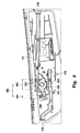
- Fig. 4 shows a front view of the locking mechanism discussed with respect to Fig. 2 .
- the locking rods 116 and 118 can be clearly seen including the respective pins 118 for engagement with the non-visible counterpart locking recesses of the vehicle.
- the bar 208 and the lever 206 of Fig. 2 both have a flat and even contact region which maximizes the area of force transmission between the lever 206 and the bar 208.
- the contact region of the lever and the bar which is the region 404 in Fig. 4 is disposed from the rotation axis of the pinion 204 by a distance 402.
- This distance 402 is at least the diameter 400 of the pinion 204. This maximizes the lever action at the bar 208 and thus minimizes the force required in order to operate the bar and thus the locking mechanism. Nevertheless, the total size of the locking mechanism is kept small.
- the handle By means of a movement of the handle (grip handle) into the z-direction, for example by means of a rotational movement about 30 degrees, a force is transmitted from the handle over the lever onto the bar of the pinion. As a result, the pinion is rotated. This results in a movement of the rack gears and thus the locking rods in a horizontal direction (y-direction). After the locking rods reached their final position, the pins of the locking rods are disengaged from the counterpart locking recesses of the vehicle and the lid of the glove box can be opened. Upon releasing the handle 120, no force is acting anymore onto the bar 208.
- the handle comprises a spring mechanism which forces the handle and thus the lever back into its non-operated position, i.e.
Landscapes
- Lock And Its Accessories (AREA)
- Vehicle Step Arrangements And Article Storage (AREA)
Claims (9)
- Mécanisme de verrouillage pour une boîte à gants (100) d'un véhicule, comprenant :- une poignée actionnable verticalement (120) pour l'accès à la boîte à gants (100), la poignée (120) comprenant un levier (206),- au moins deux tiges de verrouillage (114 ; 116) avec des goupilles (118) pour l'engagement des goupilles (118) avec un renfoncement de verrouillage correspondant du véhicule, chacune des tiges de verrouillage (114 ; 116) comprenant un engrenage à crémaillère,- un pignon (204) apte à s'engager simultanément avec les engrenages à crémaillère (200) des tiges de verrouillage (114 ; 116) comprend une barre (208) reliée au pignon (204) et en contact avec le levier (206), la barre (208) étant adaptée pour convertir un mouvement vertical du levier (206) en un mouvement de rotation du pignon (204),- dans lequel la région de contact (404) du levier (206) et de la barre (208) se trouve à une distance (402) de l'axe de rotation du pignon (204), la distance (402) étant au moins égale au diamètre (400) du pignon (204).
- Mécanisme de verrouillage selon la revendication 1, dans lequel le pignon (204) possède deux engrenages de pignon (202) situés sur des côtés opposés du pignon (204), les deux engrenages de pignon (202) étant aptes à s'engager directement avec les engrenages à crémaillère (200).
- Mécanisme de verrouillage selon la revendication 1 ou 2, dans lequel le levier (206) présente une direction d'extension allant de la poignée (120) vers la barre (208), la direction d'extension du levier (206) et de l'axe du pignon (204) étant décalées latéralement l'une par rapport à l'autre.
- Mécanisme de verrouillage selon l'une quelconque des revendications précédentes, dans lequel le mécanisme de verrouillage comprend en outre un cylindre de verrouillage (112) relié à la poignée (120) le levier (206) étant relié au cylindre de verrouillage (112).
- Mécanisme de verrouillage selon la revendication 4, dans lequel l'axe du cylindre de verrouillage (112) et l'axe du pignon (204) sont excentriques.
- Mécanisme de verrouillage selon la revendication 4 ou 5, dans lequel le levier (206) présente une direction d'extension allant de la poignée (120) vers la barre (208), la direction d'extension du levier (206) et l'axe du cylindre de verrouillage (112) étant décalées latéralement l'une par rapport à l'autre.
- Mécanisme de verrouillage selon la revendication 6, dans lequel le cylindre de verrouillage (112), le levier (206) et la barre (208) sont agencés de manière à ce qu'un mouvement de rotation du cylindre de verrouillage (112) permette la mise en contact ou la mise hors contact du levier (206) et de la barre (208).
- Mécanisme de verrouillage selon l'une quelconque des revendications précédentes, comprenant en outre un ressort de rappel pour fournir une force de couple rappelant le mouvement de rotation du pignon (204).
- Mécanisme de verrouillage selon la revendication 8, dans lequel le ressort de rappel comprend un ressort de torsion ou un ressort d'horloge.
Priority Applications (1)
| Application Number | Priority Date | Filing Date | Title |
|---|---|---|---|
| EP20120164804 EP2653638B1 (fr) | 2012-04-19 | 2012-04-19 | Mécanisme de verrouillage pour boîte à gants |
Applications Claiming Priority (1)
| Application Number | Priority Date | Filing Date | Title |
|---|---|---|---|
| EP20120164804 EP2653638B1 (fr) | 2012-04-19 | 2012-04-19 | Mécanisme de verrouillage pour boîte à gants |
Publications (2)
| Publication Number | Publication Date |
|---|---|
| EP2653638A1 EP2653638A1 (fr) | 2013-10-23 |
| EP2653638B1 true EP2653638B1 (fr) | 2014-07-30 |
Family
ID=45999688
Family Applications (1)
| Application Number | Title | Priority Date | Filing Date |
|---|---|---|---|
| EP20120164804 Active EP2653638B1 (fr) | 2012-04-19 | 2012-04-19 | Mécanisme de verrouillage pour boîte à gants |
Country Status (1)
| Country | Link |
|---|---|
| EP (1) | EP2653638B1 (fr) |
Families Citing this family (7)
| Publication number | Priority date | Publication date | Assignee | Title |
|---|---|---|---|---|
| CN104453487B (zh) * | 2014-12-09 | 2016-08-17 | 上海琦天汽车科技有限公司 | 侧翻式双侧锁定装置 |
| JP6599830B2 (ja) * | 2016-09-08 | 2019-10-30 | 株式会社ニフコ | ロック装置 |
| EP3775453B1 (fr) | 2018-04-03 | 2023-06-14 | Southco, Inc. | Serrure de boîte à gants d'un véhicule |
| US12116811B2 (en) * | 2018-08-23 | 2024-10-15 | Thomas Moloney Pty Limited | Lockable handle assembly with floating cam mechanism |
| JP7587572B2 (ja) | 2019-09-26 | 2024-11-20 | サウスコ,インコーポレイティド | 車両グローブボックスラッチ |
| JP7423508B2 (ja) * | 2020-12-25 | 2024-01-29 | 森六テクノロジー株式会社 | 開閉体のロック装置、及び、車両用収納装置 |
| EP4352329B1 (fr) * | 2021-06-11 | 2026-05-06 | Southco, Inc. | Connecteur à cliquet pour verrou de boîte à gants |
Family Cites Families (7)
| Publication number | Priority date | Publication date | Assignee | Title |
|---|---|---|---|---|
| DE10036945A1 (de) * | 2000-07-28 | 2002-02-07 | Volkswagen Ag | Verschluss, insbesondere Handschuhkastenverschluss für ein Kraftfahrzeug |
| JP3896028B2 (ja) * | 2002-04-19 | 2007-03-22 | 小島プレス工業株式会社 | 開閉ロック装置 |
| KR100535763B1 (ko) | 2003-11-19 | 2005-12-12 | 현대모비스 주식회사 | 글로브박스의 로드 작동장치 |
| EP2090468B1 (fr) * | 2008-02-12 | 2010-08-25 | Fiat Group Automobiles S.p.A. | Ensemble de boîte à gants pour le tableau de bord d'un véhicule à moteur |
| JP5367281B2 (ja) * | 2008-03-07 | 2013-12-11 | 株式会社パイオラックス | 開閉ロック装置 |
| JP5003554B2 (ja) * | 2008-03-27 | 2012-08-15 | 豊田合成株式会社 | サイドロック装置 |
| DE102008041724B4 (de) * | 2008-08-29 | 2013-09-05 | Faurecia Innenraum Systeme Gmbh | Verschluss für ein Staufach eines Kraftfahrzeugs |
-
2012
- 2012-04-19 EP EP20120164804 patent/EP2653638B1/fr active Active
Also Published As
| Publication number | Publication date |
|---|---|
| EP2653638A1 (fr) | 2013-10-23 |
Similar Documents
| Publication | Publication Date | Title |
|---|---|---|
| EP2653638A1 (fr) | Mécanisme de verrouillage pour boîte à gants | |
| EP2946051B1 (fr) | Élément de blocage pour véhicule à moteur | |
| US9109381B2 (en) | Door latch apparatus for vehicle | |
| US9316031B2 (en) | Interior apparatus of a vehicle | |
| CN105003133B (zh) | 用于机动车辆的门的闩锁 | |
| CN104863437B (zh) | 用于机动车辆的门的闩锁 | |
| EP3561204A1 (fr) | Dispositif de fermeture avec un element d'inertie | |
| US20100052341A1 (en) | Vehicle latch with secondary engagement between cam and auxiliary pawl | |
| WO2012107024A3 (fr) | Fermeture de portière de véhicule à moteur | |
| US9163434B2 (en) | Vehicle door lock apparatus | |
| US11066855B2 (en) | Glove compartment | |
| CN203592940U (zh) | 用于车辆收纳箱的锁定装置 | |
| CN107060534A (zh) | 用于释放缆索组件的惯性锁定装置 | |
| US20150069767A1 (en) | Door outside handle assembly for vehicle | |
| CN103452396B (zh) | 锁定装置、盖件及机动车辆 | |
| US11359420B2 (en) | Pivoted lockable latch actuator | |
| EP2725569B1 (fr) | Mécanisme de retenue d'affichage et dispositif d'affichage de type à ouverture et à fermeture | |
| CN103670083A (zh) | 一种用于机动车辆中能够被翻板闭合的隔室的闭合装置 | |
| CN107054229B (zh) | 一种汽车储物盒 | |
| CN103195313A (zh) | 汽车左中门锁体总成 | |
| KR101519247B1 (ko) | 슬라이드 도어 장치 | |
| CN210337764U (zh) | 用于车辆的手套箱 | |
| US20150367784A1 (en) | Vehicle trim element and an associated display system | |
| US20130241213A1 (en) | Locking system | |
| EP2295682B1 (fr) | Panneau d'instrument avec un dispositif de sécurité |
Legal Events
| Date | Code | Title | Description |
|---|---|---|---|
| PUAI | Public reference made under article 153(3) epc to a published international application that has entered the european phase |
Free format text: ORIGINAL CODE: 0009012 |
|
| 17P | Request for examination filed |
Effective date: 20121227 |
|
| AK | Designated contracting states |
Kind code of ref document: A1 Designated state(s): AL AT BE BG CH CY CZ DE DK EE ES FI FR GB GR HR HU IE IS IT LI LT LU LV MC MK MT NL NO PL PT RO RS SE SI SK SM TR |
|
| AX | Request for extension of the european patent |
Extension state: BA ME |
|
| REG | Reference to a national code |
Ref country code: DE Ref legal event code: R079 Ref document number: 602012002550 Country of ref document: DE Free format text: PREVIOUS MAIN CLASS: E05B0065120000 Ipc: E05B0083300000 |
|
| GRAP | Despatch of communication of intention to grant a patent |
Free format text: ORIGINAL CODE: EPIDOSNIGR1 |
|
| RIC1 | Information provided on ipc code assigned before grant |
Ipc: E05C 9/04 20060101ALN20140203BHEP Ipc: E05B 83/30 20140101AFI20140203BHEP |
|
| INTG | Intention to grant announced |
Effective date: 20140313 |
|
| GRAS | Grant fee paid |
Free format text: ORIGINAL CODE: EPIDOSNIGR3 |
|
| GRAA | (expected) grant |
Free format text: ORIGINAL CODE: 0009210 |
|
| AK | Designated contracting states |
Kind code of ref document: B1 Designated state(s): AL AT BE BG CH CY CZ DE DK EE ES FI FR GB GR HR HU IE IS IT LI LT LU LV MC MK MT NL NO PL PT RO RS SE SI SK SM TR |
|
| REG | Reference to a national code |
Ref country code: GB Ref legal event code: FG4D |
|
| REG | Reference to a national code |
Ref country code: CH Ref legal event code: EP |
|
| REG | Reference to a national code |
Ref country code: AT Ref legal event code: REF Ref document number: 680098 Country of ref document: AT Kind code of ref document: T Effective date: 20140815 |
|
| REG | Reference to a national code |
Ref country code: IE Ref legal event code: FG4D |
|
| REG | Reference to a national code |
Ref country code: DE Ref legal event code: R096 Ref document number: 602012002550 Country of ref document: DE Effective date: 20140911 |
|
| REG | Reference to a national code |
Ref country code: AT Ref legal event code: MK05 Ref document number: 680098 Country of ref document: AT Kind code of ref document: T Effective date: 20140730 |
|
| REG | Reference to a national code |
Ref country code: NL Ref legal event code: VDEP Effective date: 20140730 |
|
| REG | Reference to a national code |
Ref country code: LT Ref legal event code: MG4D |
|
| PG25 | Lapsed in a contracting state [announced via postgrant information from national office to epo] |
Ref country code: NO Free format text: LAPSE BECAUSE OF FAILURE TO SUBMIT A TRANSLATION OF THE DESCRIPTION OR TO PAY THE FEE WITHIN THE PRESCRIBED TIME-LIMIT Effective date: 20141030 Ref country code: BG Free format text: LAPSE BECAUSE OF FAILURE TO SUBMIT A TRANSLATION OF THE DESCRIPTION OR TO PAY THE FEE WITHIN THE PRESCRIBED TIME-LIMIT Effective date: 20141030 Ref country code: FI Free format text: LAPSE BECAUSE OF FAILURE TO SUBMIT A TRANSLATION OF THE DESCRIPTION OR TO PAY THE FEE WITHIN THE PRESCRIBED TIME-LIMIT Effective date: 20140730 Ref country code: LT Free format text: LAPSE BECAUSE OF FAILURE TO SUBMIT A TRANSLATION OF THE DESCRIPTION OR TO PAY THE FEE WITHIN THE PRESCRIBED TIME-LIMIT Effective date: 20140730 Ref country code: GR Free format text: LAPSE BECAUSE OF FAILURE TO SUBMIT A TRANSLATION OF THE DESCRIPTION OR TO PAY THE FEE WITHIN THE PRESCRIBED TIME-LIMIT Effective date: 20141031 Ref country code: ES Free format text: LAPSE BECAUSE OF FAILURE TO SUBMIT A TRANSLATION OF THE DESCRIPTION OR TO PAY THE FEE WITHIN THE PRESCRIBED TIME-LIMIT Effective date: 20140730 Ref country code: PT Free format text: LAPSE BECAUSE OF FAILURE TO SUBMIT A TRANSLATION OF THE DESCRIPTION OR TO PAY THE FEE WITHIN THE PRESCRIBED TIME-LIMIT Effective date: 20141202 Ref country code: SE Free format text: LAPSE BECAUSE OF FAILURE TO SUBMIT A TRANSLATION OF THE DESCRIPTION OR TO PAY THE FEE WITHIN THE PRESCRIBED TIME-LIMIT Effective date: 20140730 |
|
| PG25 | Lapsed in a contracting state [announced via postgrant information from national office to epo] |
Ref country code: PL Free format text: LAPSE BECAUSE OF FAILURE TO SUBMIT A TRANSLATION OF THE DESCRIPTION OR TO PAY THE FEE WITHIN THE PRESCRIBED TIME-LIMIT Effective date: 20140730 Ref country code: CY Free format text: LAPSE BECAUSE OF FAILURE TO SUBMIT A TRANSLATION OF THE DESCRIPTION OR TO PAY THE FEE WITHIN THE PRESCRIBED TIME-LIMIT Effective date: 20140730 Ref country code: IS Free format text: LAPSE BECAUSE OF FAILURE TO SUBMIT A TRANSLATION OF THE DESCRIPTION OR TO PAY THE FEE WITHIN THE PRESCRIBED TIME-LIMIT Effective date: 20141130 Ref country code: HR Free format text: LAPSE BECAUSE OF FAILURE TO SUBMIT A TRANSLATION OF THE DESCRIPTION OR TO PAY THE FEE WITHIN THE PRESCRIBED TIME-LIMIT Effective date: 20140730 Ref country code: LV Free format text: LAPSE BECAUSE OF FAILURE TO SUBMIT A TRANSLATION OF THE DESCRIPTION OR TO PAY THE FEE WITHIN THE PRESCRIBED TIME-LIMIT Effective date: 20140730 Ref country code: NL Free format text: LAPSE BECAUSE OF FAILURE TO SUBMIT A TRANSLATION OF THE DESCRIPTION OR TO PAY THE FEE WITHIN THE PRESCRIBED TIME-LIMIT Effective date: 20140730 Ref country code: RS Free format text: LAPSE BECAUSE OF FAILURE TO SUBMIT A TRANSLATION OF THE DESCRIPTION OR TO PAY THE FEE WITHIN THE PRESCRIBED TIME-LIMIT Effective date: 20140730 Ref country code: AT Free format text: LAPSE BECAUSE OF FAILURE TO SUBMIT A TRANSLATION OF THE DESCRIPTION OR TO PAY THE FEE WITHIN THE PRESCRIBED TIME-LIMIT Effective date: 20140730 |
|
| PG25 | Lapsed in a contracting state [announced via postgrant information from national office to epo] |
Ref country code: EE Free format text: LAPSE BECAUSE OF FAILURE TO SUBMIT A TRANSLATION OF THE DESCRIPTION OR TO PAY THE FEE WITHIN THE PRESCRIBED TIME-LIMIT Effective date: 20140730 Ref country code: SK Free format text: LAPSE BECAUSE OF FAILURE TO SUBMIT A TRANSLATION OF THE DESCRIPTION OR TO PAY THE FEE WITHIN THE PRESCRIBED TIME-LIMIT Effective date: 20140730 Ref country code: IT Free format text: LAPSE BECAUSE OF FAILURE TO SUBMIT A TRANSLATION OF THE DESCRIPTION OR TO PAY THE FEE WITHIN THE PRESCRIBED TIME-LIMIT Effective date: 20140730 Ref country code: DK Free format text: LAPSE BECAUSE OF FAILURE TO SUBMIT A TRANSLATION OF THE DESCRIPTION OR TO PAY THE FEE WITHIN THE PRESCRIBED TIME-LIMIT Effective date: 20140730 Ref country code: RO Free format text: LAPSE BECAUSE OF FAILURE TO SUBMIT A TRANSLATION OF THE DESCRIPTION OR TO PAY THE FEE WITHIN THE PRESCRIBED TIME-LIMIT Effective date: 20140730 Ref country code: CZ Free format text: LAPSE BECAUSE OF FAILURE TO SUBMIT A TRANSLATION OF THE DESCRIPTION OR TO PAY THE FEE WITHIN THE PRESCRIBED TIME-LIMIT Effective date: 20140730 |
|
| REG | Reference to a national code |
Ref country code: DE Ref legal event code: R097 Ref document number: 602012002550 Country of ref document: DE |
|
| PLBE | No opposition filed within time limit |
Free format text: ORIGINAL CODE: 0009261 |
|
| STAA | Information on the status of an ep patent application or granted ep patent |
Free format text: STATUS: NO OPPOSITION FILED WITHIN TIME LIMIT |
|
| 26N | No opposition filed |
Effective date: 20150504 |
|
| PG25 | Lapsed in a contracting state [announced via postgrant information from national office to epo] |
Ref country code: MC Free format text: LAPSE BECAUSE OF FAILURE TO SUBMIT A TRANSLATION OF THE DESCRIPTION OR TO PAY THE FEE WITHIN THE PRESCRIBED TIME-LIMIT Effective date: 20140730 Ref country code: LU Free format text: LAPSE BECAUSE OF FAILURE TO SUBMIT A TRANSLATION OF THE DESCRIPTION OR TO PAY THE FEE WITHIN THE PRESCRIBED TIME-LIMIT Effective date: 20150419 Ref country code: SI Free format text: LAPSE BECAUSE OF FAILURE TO SUBMIT A TRANSLATION OF THE DESCRIPTION OR TO PAY THE FEE WITHIN THE PRESCRIBED TIME-LIMIT Effective date: 20140730 |
|
| REG | Reference to a national code |
Ref country code: CH Ref legal event code: PL |
|
| REG | Reference to a national code |
Ref country code: IE Ref legal event code: MM4A |
|
| PG25 | Lapsed in a contracting state [announced via postgrant information from national office to epo] |
Ref country code: CH Free format text: LAPSE BECAUSE OF NON-PAYMENT OF DUE FEES Effective date: 20150430 Ref country code: LI Free format text: LAPSE BECAUSE OF NON-PAYMENT OF DUE FEES Effective date: 20150430 |
|
| REG | Reference to a national code |
Ref country code: FR Ref legal event code: PLFP Year of fee payment: 5 |
|
| PG25 | Lapsed in a contracting state [announced via postgrant information from national office to epo] |
Ref country code: IE Free format text: LAPSE BECAUSE OF NON-PAYMENT OF DUE FEES Effective date: 20150419 |
|
| PG25 | Lapsed in a contracting state [announced via postgrant information from national office to epo] |
Ref country code: BE Free format text: LAPSE BECAUSE OF FAILURE TO SUBMIT A TRANSLATION OF THE DESCRIPTION OR TO PAY THE FEE WITHIN THE PRESCRIBED TIME-LIMIT Effective date: 20140730 |
|
| GBPC | Gb: european patent ceased through non-payment of renewal fee |
Effective date: 20160419 |
|
| PG25 | Lapsed in a contracting state [announced via postgrant information from national office to epo] |
Ref country code: MT Free format text: LAPSE BECAUSE OF FAILURE TO SUBMIT A TRANSLATION OF THE DESCRIPTION OR TO PAY THE FEE WITHIN THE PRESCRIBED TIME-LIMIT Effective date: 20140730 |
|
| PG25 | Lapsed in a contracting state [announced via postgrant information from national office to epo] |
Ref country code: GB Free format text: LAPSE BECAUSE OF NON-PAYMENT OF DUE FEES Effective date: 20160419 |
|
| REG | Reference to a national code |
Ref country code: FR Ref legal event code: PLFP Year of fee payment: 6 |
|
| PG25 | Lapsed in a contracting state [announced via postgrant information from national office to epo] |
Ref country code: HU Free format text: LAPSE BECAUSE OF FAILURE TO SUBMIT A TRANSLATION OF THE DESCRIPTION OR TO PAY THE FEE WITHIN THE PRESCRIBED TIME-LIMIT; INVALID AB INITIO Effective date: 20120419 Ref country code: SM Free format text: LAPSE BECAUSE OF FAILURE TO SUBMIT A TRANSLATION OF THE DESCRIPTION OR TO PAY THE FEE WITHIN THE PRESCRIBED TIME-LIMIT Effective date: 20140730 |
|
| PG25 | Lapsed in a contracting state [announced via postgrant information from national office to epo] |
Ref country code: TR Free format text: LAPSE BECAUSE OF FAILURE TO SUBMIT A TRANSLATION OF THE DESCRIPTION OR TO PAY THE FEE WITHIN THE PRESCRIBED TIME-LIMIT Effective date: 20140730 |
|
| REG | Reference to a national code |
Ref country code: FR Ref legal event code: PLFP Year of fee payment: 7 |
|
| PG25 | Lapsed in a contracting state [announced via postgrant information from national office to epo] |
Ref country code: MK Free format text: LAPSE BECAUSE OF FAILURE TO SUBMIT A TRANSLATION OF THE DESCRIPTION OR TO PAY THE FEE WITHIN THE PRESCRIBED TIME-LIMIT Effective date: 20140730 |
|
| PG25 | Lapsed in a contracting state [announced via postgrant information from national office to epo] |
Ref country code: AL Free format text: LAPSE BECAUSE OF FAILURE TO SUBMIT A TRANSLATION OF THE DESCRIPTION OR TO PAY THE FEE WITHIN THE PRESCRIBED TIME-LIMIT Effective date: 20140730 |
|
| REG | Reference to a national code |
Ref country code: DE Ref legal event code: R082 Ref document number: 602012002550 Country of ref document: DE Representative=s name: PFENNING, MEINIG & PARTNER MBB PATENTANWAELTE, DE |
|
| PGFP | Annual fee paid to national office [announced via postgrant information from national office to epo] |
Ref country code: DE Payment date: 20250319 Year of fee payment: 14 |
|
| PGFP | Annual fee paid to national office [announced via postgrant information from national office to epo] |
Ref country code: FR Payment date: 20260319 Year of fee payment: 15 |