EP2653699A2 - Modulare Lüftungsöffnungs-Anordnung - Google Patents
Modulare Lüftungsöffnungs-Anordnung Download PDFInfo
- Publication number
- EP2653699A2 EP2653699A2 EP13163434.7A EP13163434A EP2653699A2 EP 2653699 A2 EP2653699 A2 EP 2653699A2 EP 13163434 A EP13163434 A EP 13163434A EP 2653699 A2 EP2653699 A2 EP 2653699A2
- Authority
- EP
- European Patent Office
- Prior art keywords
- louvers
- louver
- bleed
- discharge opening
- open position
- Prior art date
- Legal status (The legal status is an assumption and is not a legal conclusion. Google has not performed a legal analysis and makes no representation as to the accuracy of the status listed.)
- Withdrawn
Links
- 238000000034 method Methods 0.000 claims description 16
- 238000007599 discharging Methods 0.000 claims description 5
- 230000001052 transient effect Effects 0.000 claims description 5
- 239000000446 fuel Substances 0.000 claims description 4
- 239000007789 gas Substances 0.000 description 28
- 238000002485 combustion reaction Methods 0.000 description 3
- 238000011144 upstream manufacturing Methods 0.000 description 3
- 230000000740 bleeding effect Effects 0.000 description 2
- 230000006835 compression Effects 0.000 description 2
- 238000007906 compression Methods 0.000 description 2
- 230000000694 effects Effects 0.000 description 2
- 239000000567 combustion gas Substances 0.000 description 1
- 238000004891 communication Methods 0.000 description 1
- 239000002131 composite material Substances 0.000 description 1
- 238000001816 cooling Methods 0.000 description 1
- 238000013016 damping Methods 0.000 description 1
- 230000007423 decrease Effects 0.000 description 1
- 239000007769 metal material Substances 0.000 description 1
- 230000002093 peripheral effect Effects 0.000 description 1
- 238000010926 purge Methods 0.000 description 1
- 230000003685 thermal hair damage Effects 0.000 description 1
Images



Classifications
-
- F—MECHANICAL ENGINEERING; LIGHTING; HEATING; WEAPONS; BLASTING
- F02—COMBUSTION ENGINES; HOT-GAS OR COMBUSTION-PRODUCT ENGINE PLANTS
- F02C—GAS-TURBINE PLANTS; AIR INTAKES FOR JET-PROPULSION PLANTS; CONTROLLING FUEL SUPPLY IN AIR-BREATHING JET-PROPULSION PLANTS
- F02C6/00—Plural gas-turbine plants; Combinations of gas-turbine plants with other apparatus; Adaptations of gas-turbine plants for special use
- F02C6/04—Gas-turbine plants providing heated or pressurised working fluid for other apparatus, e.g. without mechanical power output
- F02C6/06—Gas-turbine plants providing heated or pressurised working fluid for other apparatus, e.g. without mechanical power output providing compressed gas
- F02C6/08—Gas-turbine plants providing heated or pressurised working fluid for other apparatus, e.g. without mechanical power output providing compressed gas the gas being bled from the gas-turbine compressor
-
- F—MECHANICAL ENGINEERING; LIGHTING; HEATING; WEAPONS; BLASTING
- F02—COMBUSTION ENGINES; HOT-GAS OR COMBUSTION-PRODUCT ENGINE PLANTS
- F02C—GAS-TURBINE PLANTS; AIR INTAKES FOR JET-PROPULSION PLANTS; CONTROLLING FUEL SUPPLY IN AIR-BREATHING JET-PROPULSION PLANTS
- F02C3/00—Gas-turbine plants characterised by the use of combustion products as the working fluid
- F02C3/04—Gas-turbine plants characterised by the use of combustion products as the working fluid having a turbine driving a compressor
- F02C3/13—Gas-turbine plants characterised by the use of combustion products as the working fluid having a turbine driving a compressor having variable working fluid interconnections between turbines or compressors or stages of different rotors
-
- F—MECHANICAL ENGINEERING; LIGHTING; HEATING; WEAPONS; BLASTING
- F02—COMBUSTION ENGINES; HOT-GAS OR COMBUSTION-PRODUCT ENGINE PLANTS
- F02C—GAS-TURBINE PLANTS; AIR INTAKES FOR JET-PROPULSION PLANTS; CONTROLLING FUEL SUPPLY IN AIR-BREATHING JET-PROPULSION PLANTS
- F02C9/00—Controlling gas-turbine plants; Controlling fuel supply in air- breathing jet-propulsion plants
- F02C9/16—Control of working fluid flow
- F02C9/18—Control of working fluid flow by bleeding, bypassing or acting on variable working fluid interconnections between turbines or compressors or their stages
-
- F—MECHANICAL ENGINEERING; LIGHTING; HEATING; WEAPONS; BLASTING
- F02—COMBUSTION ENGINES; HOT-GAS OR COMBUSTION-PRODUCT ENGINE PLANTS
- F02K—JET-PROPULSION PLANTS
- F02K3/00—Plants including a gas turbine driving a compressor or a ducted fan
- F02K3/02—Plants including a gas turbine driving a compressor or a ducted fan in which part of the working fluid by-passes the turbine and combustion chamber
- F02K3/04—Plants including a gas turbine driving a compressor or a ducted fan in which part of the working fluid by-passes the turbine and combustion chamber the plant including ducted fans, i.e. fans with high volume, low pressure outputs, for augmenting the jet thrust, e.g. of double-flow type
- F02K3/075—Plants including a gas turbine driving a compressor or a ducted fan in which part of the working fluid by-passes the turbine and combustion chamber the plant including ducted fans, i.e. fans with high volume, low pressure outputs, for augmenting the jet thrust, e.g. of double-flow type controlling flow ratio between flows
-
- F—MECHANICAL ENGINEERING; LIGHTING; HEATING; WEAPONS; BLASTING
- F05—INDEXING SCHEMES RELATING TO ENGINES OR PUMPS IN VARIOUS SUBCLASSES OF CLASSES F01-F04
- F05D—INDEXING SCHEME FOR ASPECTS RELATING TO NON-POSITIVE-DISPLACEMENT MACHINES OR ENGINES, GAS-TURBINES OR JET-PROPULSION PLANTS
- F05D2260/00—Function
- F05D2260/50—Kinematic linkage, i.e. transmission of position
-
- F—MECHANICAL ENGINEERING; LIGHTING; HEATING; WEAPONS; BLASTING
- F05—INDEXING SCHEMES RELATING TO ENGINES OR PUMPS IN VARIOUS SUBCLASSES OF CLASSES F01-F04
- F05D—INDEXING SCHEME FOR ASPECTS RELATING TO NON-POSITIVE-DISPLACEMENT MACHINES OR ENGINES, GAS-TURBINES OR JET-PROPULSION PLANTS
- F05D2260/00—Function
- F05D2260/60—Fluid transfer
- F05D2260/606—Bypassing the fluid
-
- Y—GENERAL TAGGING OF NEW TECHNOLOGICAL DEVELOPMENTS; GENERAL TAGGING OF CROSS-SECTIONAL TECHNOLOGIES SPANNING OVER SEVERAL SECTIONS OF THE IPC; TECHNICAL SUBJECTS COVERED BY FORMER USPC CROSS-REFERENCE ART COLLECTIONS [XRACs] AND DIGESTS
- Y02—TECHNOLOGIES OR APPLICATIONS FOR MITIGATION OR ADAPTATION AGAINST CLIMATE CHANGE
- Y02T—CLIMATE CHANGE MITIGATION TECHNOLOGIES RELATED TO TRANSPORTATION
- Y02T50/00—Aeronautics or air transport
- Y02T50/60—Efficient propulsion technologies, e.g. for aircraft
Definitions
- the subject matter disclosed herein relates generally to bleed air systems for gas turbine engines, and, more specifically, to bleed air systems capable of providing pressure drops, acoustic improvements, and desirable flow properties.
- air is pressurized in a compression module.
- the air channeled through the compression module is mixed with fuel in a combustor and ignited, generating hot combustion gases, which flow through turbine stages that extract energy therefrom for powering the fan and compressor rotors and generate engine thrust to propel an aircraft in flight or to power a load, such as an electrical generator.
- a portion of the high-pressure air such as, for example, bleed air from a compressor, may be extracted or bled from the compressor for various needs.
- these needs include, for example, compressor flow bleeding which may be used to improve operability as well as to provide turbine cooling, bearing sump pressurization, purge air, or aircraft environment control.
- the air may be bled off from the compressor using bleed slots located over specific portions or stages of the compressor.
- the compressor may pump more air than is required for needs including the combustion process.
- a portion of the excess bleed air from the compressor may be routed through bleed conduits and exhausted into the bypass flow stream, engine exhaust, or to ambient.
- the pressure and temperature of the air stream bled from the compressor may be very high.
- bleed air pressure may be greater than about 1375 kPa and the bleed air temperature may be greater than about 538 degrees C.
- TBV transient bleed valve system
- VBV variable bleed valve
- the exhaust area of some conventional bleed systems may be oversized to lower the flow velocity at the exhaust location to assure that the acoustic requirements are met for the application.
- the exhaust area, as well as the expansions between the source pressure and exhaust, may contribute to the large size and/or weight of these systems.
- the surrounding structure may be made of lightweight composite material or of other metallic material with lesser temperature capability.
- bypass duct components In some applications (e.g., aircraft), it may be necessary to direct bleed air flow into the bypass stream to avoid thermal damage to bypass duct components.
- At least one solution for the above-mentioned problem(s) is provided by the present disclosure to include example embodiments, provided for illustrative teaching and not meant to be limiting.
- An example louver system for a gas turbine engine bleed system may include a bleed system discharge opening arranged to vent bleed air from a bleed flow conduit and/or a plurality of pivotable louvers disposed proximate the discharge opening, the pivotable louvers being pivotable between a shut position and an open position. In the shut position, individual louvers may at least partially obstruct the discharge opening. In the open position, individual louvers may at least partially control a direction of flow of the bleed air exiting the discharge opening.
- An example gas turbine engine may include a compressor; a combustor arranged to combust fuel in compressed air received from the compressor; a turbine configured to receive hot, pressurized gas from the combustor and to drive the compressor; a bleed conduit arranged to receive bleed air from the compressor; and/or a louver system operatively coupled to the bleed conduit.
- the louver system may include a plurality of louvers disposed in a discharge opening, the plurality of louvers being pivotable between a shut position and an open position.
- An example method of operating a bleed system associated with a gas turbine engine may include receiving a flow of bleed air from a compressor of a gas turbine engine at a discharge opening; pivoting a plurality of louvers disposed in the discharge opening from a shut position to an open position; discharging the flow of bleed air through the discharge opening; and directing the flow of bleed air through the discharge opening using the plurality of louvers.
- the present disclosure includes, inter alia, gas turbine engines, bleed air systems, and methods of operating bleed air systems.
- FIG. 1 is a schematic cross-sectional view of a gas turbine engine (GTE) 10 including an example louver system 100, according to at least some aspects of the present disclosure.
- GTE 10 may include a bleed system 40, which may incorporate louver system 100.
- GTE 10 may include a core gas turbine engine 12 that includes a high-pressure compressor 14, a combustor 16, and/or a high-pressure turbine 18.
- GTE 10 may also include a low-pressure compressor 19, a low-pressure turbine 20, and/or a fan assembly 22.
- air may flow through fan assembly 22.
- a portion of the air discharged from fan assembly 22 may be channeled to high-pressure compressor 14, where it may be further compressed and channeled to combustor 16. Products of combustion from combustor 16 may be utilized to drive high-pressure turbine 18 and/or low-pressure turbine 20.
- Another portion of the air discharged from fan assembly 22 may bypass core gas turbine engine 10 and/or may be referred to as a bypass flow stream 4.
- bleed system 40 a portion of the compressed air produced by high-pressure compressor 14 may be routed through bleed system 40, thereby becoming bleed air 2.
- Bleed air 2 from high-pressure compressor 14 may enter a bleed flow conduit 44.
- Bleed air 2 may pass through bleed flow conduit 44, a muffling device 46, and/or louver system 100, which may direct bleed air 2 into a flow path, such as the bypass flow stream 4.
- Bypass flow stream 4 may flow through a duct at partially defined by bypass duct walls 148, 149.
- Flow of bleed air 2 through bleed flow conduit 44 may be controlled by a transient bleed valve 45.
- transient bleed valve 45 may fluidicly interpose compressor 14 and bleed conduit 44.
- Muffling device 46 may fluidicly interpose bleed conduit 44 and discharge opening 48.
- Louver system 100 may be in flow communication with bleed flow conduit 44 such that bleed air 2 is discharged as exit flow stream 5 into bypass flow stream 4. Louver system 100 may direct exit flow stream 5 and/or may facilitate mixing of exit flow stream 5 and bypass flow stream 4. Some example embodiments may include one or more structures configured to assist in controlling exit flow stream 5, such as an aero chimney, as described in U.S. Patent Application Publication No. 2011/0265490 , which is incorporated herein by reference.
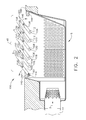
- FIG. 2 is a cross-sectional view of an example louver system 100 in an open position, according to at least some aspects of the present disclosure.
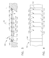
- FIG. 3 is a cross-sectional view of an example louver system 100 in a shut position, according to at least some aspects of the present disclosure.
- Louver system 100 may be disposed proximate a bleed system discharge opening 48, which may be arranged to vent bleed air from a bleed conduit 44.
- Louver system 100 may include a plurality of louvers 102, 104, 106, 108, 110, 112, which may pivotably disposed, such as by pivot pins 114, 116, 118, 120, 122, 124, respectively.
- Louvers 102, 104, 106, 108, 110, 112 may comprise respective trailing edges 150, 152, 154, 156, 158, 160.
- trailing edges 150, 152, 154, 156, 158, 160 may be located generally opposite pivot pins 114, 116, 118, 120, 122, 124, respectively.
- Pivot pins 114, 116, 118, 120, 122, 124 may be generally upstream and trailing edges 150, 152, 154, 156, 158, 160 may be generally downstream with respect to bleed air 2 and/or exit flow stream 5.
- Louvers 102, 104, 106, 108, 110, 112 may be pivotable between an open position (e.g., FIG. 2 ) and a shut position (e.g., FIG. 3 ).
- individual louvers 102, 104, 106, 108, 110, 112 may at least partially control a direction of exit flow stream 5 of bleed air 2 exiting discharge opening 48.
- louvers 102, 104, 106, 108, 110, 112 may direct exit flow stream 5 generally upward and to the right in FIG. 2 .
- An example louver system 100 installed in a turbofan aircraft engine may be configured to use louvers 102, 104, 106, 108, 110, 112 to direct exit flow 5 generally away from bypass duct walls 148, 149 ( FIG. 1 ).
- individual louvers 102, 104, 106, 108, 110, 112 may at least partially obstruct discharge opening 48.
- the plurality of louvers 102, 104, 106, 108, 110, 112 may substantially obstruct discharge opening 48.
- substantially obstructing discharge opening 48 when shut may enable louvers 102, 104, 106, 108, 110, 112 to prevent acoustic effects (e.g., whistling) and/or undesirable flow effects that may be caused by a substantially open discharge opening 48 with substantially no exit flow stream 5.
- louver system 48 may include a connecting rod 126 operatively coupled to two or more individual louvers 102, 104, 106, 108, 110, 112. Some example embodiments may include more than one connecting rod (see, e.g., FIG. 5 ).
- connecting rod 126 may be pivotably connected to louvers 102, 104, 106, 108, 110, 112 by pivot pins 128, 130, 132, 134, 136, 138.
- Connecting rod 126 may provide substantially coordinated pivoting of louvers 102, 104, 106, 108, 110, 112.
- louvers 102, 104, 106, 108, 110, 112 may pivot between open and shut positions in a substantially coordinated manner.
- louver system 100 may include an open position stopper 140, which may be arranged to limit pivoting of one or more of louvers 102, 104, 106, 108, 110, 112 in an opening direction 142 (e.g., FIG. 3 ).
- open position stopper 140 may directly limit pivoting of louver 102 in opening direction 142 by impeding rotation of louver 102 beyond a predetermined amount.
- Louvers 104, 106, 108, 110, 112 may also be limited in pivoting in opening direction 142 by louver 102 contacting open position stopper 140 because louvers 102, 104, 106, 108, 110, 112 may be linked together by connecting rod 126.
- louver system 100 may include a shut position stopper 144, which may be arranged to limit pivoting of one or more of louvers 102, 104, 106, 108, 110, 112 in a shutting direction 146 (e.g., FIG. 3 ).
- shut position stopper 144 may directly limit pivoting of louver 112 in shutting direction 146 by impeding rotation of louver 112 beyond a predetermined amount.
- Louvers 102, 104, 106, 108, 110 may also be limited in pivoting in shutting direction 146 by louver 112 contacting shut position stopper 144 because louvers 102, 104, 106, 108, 110, 112 may be linked together by connecting rod 126 and/or because louvers 102, 104, 106, 108, 110 may lie against louvers 104, 106, 108, 110, 112, respectively, in the shut position.
- Some example embodiments according to at least some aspects of the present disclosure may include more than one open position stopper 140 and/or more than one shut position stopper 144 (e.g., FIG. 3 ).
- An example embodiment may include open position stoppers 140 and/or shut position stoppers 144 associated with individual louvers 102, 104, 106, 108, 110, 112 and/or with groups of louvers 102, 104, 106, 108, 110, 112.
- louvers 102, 104, 106, 108, 110, 112 may pivot from the shut position to the open position upon receiving bleed air 2 flow from compressor 14. For example, a pressure differential across shut louvers 102, 104, 106, 108, 110, 112 may cause louvers 102, 104, 106, 108, 110, 112 to open. Upon substantially stopping the flow of bleed air 2 from compressor 14, louvers 102, 104, 106, 108, 110, 112 may pivot from the open position to the shut position. Louvers 102, 104, 106, 108, 110, 112 may remain in the shut position during conditions when there is substantially no bleed air 2 flow.
- FIG. 4 is a plan view of an example louver system 100, according to at least some aspects of the present disclosure.
- trailing edges 150, 152, 154, 156, 158, 160 may be generally straight and/or may include rounded peripheral corners.
- FIG. 5 is a cross-sectional view of an example louver system 200 including a first connecting rod 226 and a second connecting rod 227, according to at least some aspects of the present disclosure.
- Louver system 200 may be mounted in bleed system discharge opening 48.
- Louver system 200 may include a plurality of louvers 202, 204, 206, 208, 210, 212, which may pivotably disposed, such as by pivot pins 214, 216, 218, 220, 222, 224, respectively.
- Louvers 202, 204, 206, 208, 210, 212 may comprise respective trailing edges 250, 252, 254, 256, 258, 260 (e.g., FIG. 5 ).
- trailing edges 250, 252, 254, 256, 258, 260 may be located generally opposite pivot pins 214, 216, 218, 220, 222, 224, respectively.
- Pivot pins 214, 216, 218, 220, 222, 224 may be generally upstream and trailing edges 250, 252, 254, 256, 258, 260 may be generally downstream with respect to exit flow stream 5.
- louvers 202, 204, 206, 208, 210, 212 of louver system 200 may be pivotable between an open position (e.g., louvers 202, 204, 206) and a shut position (e.g., louvers 208, 210, 212) (e.g., FIG. 5 ).
- an open position e.g., louvers 202, 204, 206
- a shut position e.g., louvers 208, 210, 212
- individual louvers 202, 204, 206, 208, 210, 212 may at least partially control a direction of exit flow stream 5 of bleed air 2 exiting discharge opening 48.
- one or more louvers 202, 204, 206, 208, 210, 212 may direct exit flow stream 5 generally upward and to the right in FIG. 5 .
- An example louver system 200 installed in a turbofan aircraft engine may be configured to use one or more louvers 202, 204, 206, 208, 210, 212
- individual louvers 202, 204, 206, 208, 210, 212 may at least partially obstruct discharge opening 48.
- the plurality of louvers 202, 204, 206, 208, 210, 212 may substantially obstruct discharge opening 48.
- first connecting rod 226 may be operatively coupled to two or more individual louvers 202, 204, 206 comprising a first group 262 of louvers and/or second connecting rod 227 may be operatively coupled to two or more individual louvers 208, 210, 212 comprising a second group 264 of louvers (e.g., FIG. 5 ).
- First connecting rod 226 may be pivotably connected to louvers 202, 204, 206 by pivot pins 228, 230, 232.
- First connecting rod 226 may provide substantially coordinated pivoting of first group 262 of louvers.
- louvers 202, 204, 206 may pivot between open and shut positions in a substantially coordinated manner.
- Second connecting rod 227 may be pivotably connected to louvers 208, 210, 212 by pivot pins 234, 236, 238. Second connecting rod 227 may provide substantially coordinated pivoting of first group 264 of louvers. For example, louvers 208, 210, 212 may pivot between open and shut positions in a substantially coordinated manner.
- louver system 200 may include an open position stopper 240, which may be arranged to limit pivoting of one or more of louvers 202, 204, 206, 208, 210, 212 in an opening direction 242.
- open position stopper 240 may directly limit pivoting of louver 202 in opening direction 242 by impeding rotation of louver 202 beyond a predetermined amount.
- Louvers 204, 206 may also be limited in pivoting in opening direction 242 by louver 202 contacting open position stopper 240 because louvers 202, 204, 206 may be linked together by first connecting rod 226.
- louver system 200 may include a shut position stopper 244, which may be arranged to limit pivoting of one or more of louvers 202, 204, 206, 208, 210, 212 in a shutting direction 246.
- shut position stopper 244 may directly limit pivoting of louver 212 in shutting direction 246 by impeding rotation of louver 212 beyond a predetermined amount.
- Louvers 202, 204, 206, 208, 210 may also be limited in pivoting in shutting direction 246 by louver 212 contacting shut position stopper 244 because louvers 202, 204, 206, 208, 210, 212 may be linked together by first connecting rod 226 and/or second connecting rod 227 and/or because louvers 202, 204, 206, 208, 210 may lie against louvers 204, 206, 208, 210, 212, respectively, in the shut position.
- first connecting rod 226 and second connecting rod 227 may be independently operable such that first group 262 of louvers and second group 264 of louvers may be at least partially independently pivotable (e.g., FIG. 5 ).
- louver system 200 may be configured such that first group 262 of louvers may be open at low and high bleed air 2 flow rates and/or second group 264 of louvers may be open at relatively high bleed air 2 flow rates and may be shut at relatively low flow rates.
- bleed air 2 flow may initially cause first group 262 of louvers to open, thereby discharging bleed air 2 as exit flow stream 5.
- Second group 264 of louvers may be maintained in the shut position.
- second group 264 of louvers may pivot to the open position. If the flow rate of bleed air 2 decreases, second group 264 of louvers may pivot to the shut position.
- first group 262 of louvers may pivot from the open position to the shut position.
- FIG. 6 is a plan view of an example louver system 300 including louvers 302, 304, 306, 308, 310, 312 with scalloped trailing edges 350, 352, 354 and/or chevron-shaped trailing edges 356, 358, 360, respectively, according to at least some aspects of the present disclosure.
- An example scalloped trailing edge 350 may include a plurality of alternating, generally curved projections 370, 372, 374 and/or recesses 376, 378.
- Some example embodiments may include a plurality of louvers having substantially the same shape of trailing edge, and some example embodiments may include a plurality of louvers having a plurality of different trailing edge shapes.
- FIG. 7 is a perspective view of an example louver 400 including a grooved trailing edge 404, according to at least some aspects of the present disclosure.
- Louver 400 may be pivotably mounted in a louver system generally as described in connection with other embodiments herein.
- louver 400 may receive a pivot pin through hole 402.
- Trailing edge 404 may be grooved, including a plurality of recesses 406, 408, 410, 412 interposed between a plurality of projections 414, 416, 418, 420, 422.
- recesses 406, 408, 410, 412 may be located on an area of trailing edge 404 that is generally opposite bypass flow stream 4.
- trailing edges with mixing features may improve mixing of exit flow stream 5 with bypass flow stream 4, for example.
- the sizes, proportions, and/or locations of projections 370, 372, 374, recesses 376, 378, projections 414, 416, 418, 420, 422, and/or recesses 406, 408, 410, 412 may be adjusted to achieve desired flow mixing characteristics.
- Some example embodiments may include one or more dampers operatively connected to one or more louvers. Such dampers may prevent and or limit flutter of the louvers.
- An example damper 161 may comprise a torsion spring operatively coupled between louver 102 and pivot pin 114, which may be staitionary. Damper 161 may initially resist opening movement of louver 102 until the differential pressure across louver 102 is sufficient to overcome the spring force.
- Alternative example damping systems may include one or more dampers operatively coupled to connecting rod 126 and/or one or more dampers operatively coupled between a rotating pivot pin 114 and a stationary part, such as open position stopper 140.
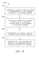
- FIG. 8 is flow chart of an example method 800 of operating a bleed system associated with a gas turbine engine, according to at least some aspects of the present disclosure.
- Method 800 may include an operation 802, which may include receiving a flow of bleed air from a compressor of a gas turbine engine at a discharge opening.
- Operation 802 may be followed by an operation 804, which may include pivoting a plurality of louvers disposed in the discharge opening from a shut position to an open position.
- Operation 804 may be followed by operation 806, which may include, discharging the flow of bleed air through the discharge opening.
- Operation 806 may be followed by operation 808, which may include directing the flow of bleed air through the discharge opening using the plurality of louvers.
Landscapes
- Engineering & Computer Science (AREA)
- Chemical & Material Sciences (AREA)
- Combustion & Propulsion (AREA)
- Mechanical Engineering (AREA)
- General Engineering & Computer Science (AREA)
- Physics & Mathematics (AREA)
- Fluid Mechanics (AREA)
- Structures Of Non-Positive Displacement Pumps (AREA)
- Control Of Turbines (AREA)
- Soundproofing, Sound Blocking, And Sound Damping (AREA)
- Air-Flow Control Members (AREA)
Applications Claiming Priority (1)
| Application Number | Priority Date | Filing Date | Title |
|---|---|---|---|
| US13/448,517 US9399951B2 (en) | 2012-04-17 | 2012-04-17 | Modular louver system |
Publications (2)
| Publication Number | Publication Date |
|---|---|
| EP2653699A2 true EP2653699A2 (de) | 2013-10-23 |
| EP2653699A3 EP2653699A3 (de) | 2017-05-17 |
Family
ID=48139736
Family Applications (1)
| Application Number | Title | Priority Date | Filing Date |
|---|---|---|---|
| EP13163434.7A Withdrawn EP2653699A3 (de) | 2012-04-17 | 2013-04-11 | Modulare Lüftungsöffnungs-Anordnung |
Country Status (6)
| Country | Link |
|---|---|
| US (1) | US9399951B2 (de) |
| EP (1) | EP2653699A3 (de) |
| JP (1) | JP2013221520A (de) |
| CN (1) | CN103375304B (de) |
| BR (1) | BR102013008566A2 (de) |
| CA (1) | CA2811821A1 (de) |
Cited By (6)
| Publication number | Priority date | Publication date | Assignee | Title |
|---|---|---|---|---|
| FR3018096A1 (fr) * | 2014-03-03 | 2015-09-04 | Snecma | Conduit de decharge pour une turbomachine |
| WO2016156739A1 (fr) * | 2015-04-01 | 2016-10-06 | Snecma | Conduit de veine de décharge d'une turbomachine comprenant une grille vbv à calage variable |
| FR3034462A1 (fr) * | 2015-04-01 | 2016-10-07 | Snecma | Conduit de veine de decharge d'une turbomachine comprenant une grille vbv a section variable |
| EP3088703A1 (de) * | 2015-04-30 | 2016-11-02 | General Electric Company | Turbinenmotorwärmeverwaltung |
| GB2550201A (en) * | 2016-05-13 | 2017-11-15 | Rolls Royce Plc | Gas turbine engine |
| FR3111948A1 (fr) * | 2020-06-30 | 2021-12-31 | Safran Aircraft Engines | vanne de décharge pour prélever du fluide circulant dans une veine de turbomachine |
Families Citing this family (19)
| Publication number | Priority date | Publication date | Assignee | Title |
|---|---|---|---|---|
| ES2621658T3 (es) * | 2012-08-09 | 2017-07-04 | MTU Aero Engines AG | Disposición conductora de corriente para la refrigeración de la carcasa de turbina de baja presión de un motor a reacción de turbina de gas |
| US20140338360A1 (en) * | 2012-09-21 | 2014-11-20 | United Technologies Corporation | Bleed port ribs for turbomachine case |
| GB201322833D0 (de) | 2013-12-23 | 2014-02-12 | Rolls Royce Plc | |
| FR3036136B1 (fr) * | 2015-05-15 | 2019-07-12 | Safran | Moyeu de carter intermediaire pour turboreacteur d'aeronef comportant un conduit de decharge composite |
| FR3037617B1 (fr) | 2015-06-17 | 2019-06-28 | Safran Aircraft Engines | Conduit de veine de decharge d'une turbomachine comprenant une grille vbv a section variable et actionnement passif |
| US10077740B2 (en) * | 2015-10-16 | 2018-09-18 | The Boeing Company | Folding door thrust reversers for aircraft engines |
| US10794282B2 (en) * | 2016-01-25 | 2020-10-06 | Rolls-Royce North American Technologies Inc. | Inlet turbine for high-mach engines |
| US10934942B2 (en) | 2016-02-16 | 2021-03-02 | Rolls-Royce North American Technologies Inc. | Inlet turbine and transmission for high-mach engines |
| ITUA20161507A1 (it) * | 2016-03-09 | 2017-09-09 | Gen Electric | Turbomotore a gas con una derivazione d'aria. |
| CN105840314B (zh) * | 2016-04-26 | 2017-09-19 | 中科合肥微小型燃气轮机研究院有限责任公司 | 带储热功能的燃气轮机试验台排气系统 |
| US10221773B2 (en) | 2016-10-07 | 2019-03-05 | General Electric Company | Bleed valve assembly for a gas turbine engine |
| US10233845B2 (en) | 2016-10-07 | 2019-03-19 | General Electric Company | Bleed valve assembly for a gas turbine engine |
| CN108267010B (zh) * | 2018-03-28 | 2023-10-27 | 中冶长天国际工程有限责任公司 | 一种消除侧风影响的燃气喷吹装置及喷吹方法 |
| GB201807267D0 (en) * | 2018-05-03 | 2018-06-20 | Rolls Royce Plc | Louvre offtake arrangement |
| GB201808852D0 (en) * | 2018-05-31 | 2018-07-18 | Rolls Royce Plc | Gas turbine engine |
| US11078842B2 (en) * | 2019-03-26 | 2021-08-03 | Raytheon Technologies Corporation | Exhaust distribution manifold |
| US10927761B2 (en) | 2019-04-17 | 2021-02-23 | General Electric Company | Refreshing heat management fluid in a turbomachine |
| US11702995B2 (en) | 2020-07-15 | 2023-07-18 | Pratt & Whitney Canada Corp. | Devices and methods for guiding bleed air in a turbofan engine |
| FR3115837B1 (fr) * | 2020-11-03 | 2025-09-19 | Safran Aircraft Engines | Ensemble pour turbomachine d’aeronef a double flux, l’ensemble etant equipe d’ailettes de decharge d’air pilotees en incidence |
Family Cites Families (101)
| Publication number | Priority date | Publication date | Assignee | Title |
|---|---|---|---|---|
| US700785A (en) | 1901-03-22 | 1902-05-27 | Albert L Kull | Muffler for explosive or other engines. |
| US1473349A (en) | 1921-04-01 | 1923-11-06 | Kach Robert | Gas mixer |
| US1539595A (en) | 1921-10-10 | 1925-05-26 | Powell Herbert Spencer | Muffler for explosive engines |
| US1697794A (en) | 1927-02-28 | 1929-01-01 | Gen Motors Corp | Exhaust-manifold muffler |
| US1794276A (en) | 1929-12-14 | 1931-02-24 | John J Bowes | Exhaust muffler |
| US2701557A (en) | 1950-11-24 | 1955-02-08 | Axiuer J Ramey | Atomizing and mixing device for internal-combustion engines |
| US2919761A (en) | 1957-05-13 | 1960-01-05 | Vernon N Holderman | Mufflers |
| US2929248A (en) | 1957-11-13 | 1960-03-22 | Bailey Meter Co | Flow meter |
| FR1245851A (fr) | 1958-12-29 | 1960-11-10 | Pot d'échappement pour véhicules à moteur à combustion interne | |
| US3016972A (en) | 1959-04-10 | 1962-01-16 | Rebert J Dugas | Muffler for an internal combustion engine |
| US3120877A (en) | 1960-10-27 | 1964-02-11 | Curtiss Wright Corp | Exhaust noise suppressor for reaction engines |
| US3159238A (en) | 1960-12-01 | 1964-12-01 | Curtiss Wright Corp | Diffuser screen with heat-insulating rungs for exhaust noise suppressor for reactionengines |
| US3105570A (en) | 1962-04-17 | 1963-10-01 | Bezemes Nicholas | Internal combustion engine exhaust muffler |
| US3191630A (en) | 1963-04-11 | 1965-06-29 | Cottrell Res Inc | Gas flow control system for sub-sonic divergent diffusers |
| US3338331A (en) | 1965-03-05 | 1967-08-29 | Walker Mfg Co | Exhaust system with plural silencing units |
| US3398881A (en) | 1967-01-10 | 1968-08-27 | United Aircraft Corp | Compressor bleed device |
| US3545492A (en) | 1968-05-16 | 1970-12-08 | Armco Steel Corp | Multiple plate throttling orifice |
| US3493169A (en) | 1968-06-03 | 1970-02-03 | United Aircraft Corp | Bleed for compressor |
| US3572391A (en) | 1969-07-10 | 1971-03-23 | Hirsch Abraham A | Flow uniformizing baffling for closed process vessels |
| US3632223A (en) | 1969-09-30 | 1972-01-04 | Gen Electric | Turbine engine having multistage compressor with interstage bleed air system |
| US3665965A (en) | 1970-05-26 | 1972-05-30 | Masonellan International Inc | Apparatus for reducing flowing fluid pressure with low noise generation |
| US3840051A (en) | 1971-03-11 | 1974-10-08 | Mitsubishi Heavy Ind Ltd | Straightener |
| US3692140A (en) | 1971-04-05 | 1972-09-19 | Cloyd D Smith | Exhaust noise suppressor for gas turbine |
| US4130173A (en) | 1971-10-01 | 1978-12-19 | Vought Corporation | Apparatus and method for reducing flow disturbances in a flowing stream of compressible fluid |
| US3777489A (en) | 1972-06-01 | 1973-12-11 | Gen Electric | Combustor casing and concentric air bleed structure |
| DE2458709C3 (de) | 1973-12-11 | 1978-10-12 | Electricite De France Service National, Paris | Axialgebläse |
| US3945759A (en) | 1974-10-29 | 1976-03-23 | General Electric Company | Bleed air manifold |
| US3964519A (en) | 1974-11-18 | 1976-06-22 | Air Monitor Corporation | Fluid velocity equalizing apparatus |
| DE2530800A1 (de) | 1975-07-10 | 1977-01-27 | Volkswagenwerk Ag | Verbindungsleitung innerhalb einer auspuffanlage eines kraftfahrzeuges |
| GB1547168A (en) | 1975-09-25 | 1979-06-06 | British Gas Corp | Gas-flow noise reduction systems |
| US4022112A (en) | 1975-12-15 | 1977-05-10 | The Bendix Corporation | Flow through cap for attenuating any noise caused by air flow in a pneumatic servomotor |
| NL181292C (nl) | 1976-06-08 | 1987-07-16 | Nederlandse Gasunie Nv | Inrichting voor het verbeteren van het stromingsprofiel in een gasleiding. |
| US4128769A (en) | 1976-09-27 | 1978-12-05 | The Garrett Corporation | Eductor muffler |
| FR2370867A1 (fr) | 1976-11-16 | 1978-06-09 | Pellerin Albert | Dispositif rendant plus homogene le melange air-essence dans les moteurs a explosion |
| US4156344A (en) | 1976-12-27 | 1979-05-29 | The Boeing Company | Inlet guide vane bleed system |
| US4244440A (en) | 1978-12-01 | 1981-01-13 | General Electric Company | Apparatus for suppressing internally generated gas turbine engine low frequency noise |
| US4244441A (en) | 1979-07-31 | 1981-01-13 | The Garrett Corporation | Broad band acoustic attenuator |
| US4375841A (en) | 1981-06-18 | 1983-03-08 | Fluid Kinetics Corporation | Fluid flow apparatus for accommodating a pressure drop |
| JPS5897515A (ja) * | 1981-12-04 | 1983-06-10 | Nissan Motor Co Ltd | ベンチレ−タグリル |
| US4463552A (en) | 1981-12-14 | 1984-08-07 | United Technologies Corporation | Combined surge bleed and dust removal system for a fan-jet engine |
| US4537277A (en) | 1982-12-03 | 1985-08-27 | The Secretary Of State For Defence In Her Britannic Majesty's Government Of The United Kingdom Of Great Britain And Northern Ireland | Silencer for high velocity gas flow |
| EP0122254B1 (de) | 1983-04-08 | 1987-06-10 | AVL Gesellschaft für Verbrennungskraftmaschinen und Messtechnik mbH.Prof.Dr.Dr.h.c. Hans List | Kraftfahrzeug |
| US4685533A (en) | 1985-12-27 | 1987-08-11 | General Dynamics, Pomona Division | Exhaust dissipator device |
| GB2196911B (en) * | 1986-10-30 | 1990-03-14 | Rolls Royce Plc | Thrust reverser |
| AU598944B2 (en) | 1987-07-22 | 1990-07-05 | Engenuity Pty Ltd | A gas blow-off attenuator |
| US4890691A (en) | 1988-11-16 | 1990-01-02 | Ching Ho Chen | Muffler |
| US4979587A (en) | 1989-08-01 | 1990-12-25 | The Boeing Company | Jet engine noise suppressor |
| JP2606466B2 (ja) * | 1991-03-25 | 1997-05-07 | 三菱電機株式会社 | 空気調和機の風向制御装置 |
| US5205719A (en) | 1992-01-13 | 1993-04-27 | Copeland Corporation | Refrigerant compressor discharge muffler |
| US5327941A (en) | 1992-06-16 | 1994-07-12 | The United States Of America As Represented By The Secretary Of The Navy | Cascade orificial resistive device |
| US5429102A (en) | 1992-06-23 | 1995-07-04 | Anhydrous Devices, Inc. | Fuel saving device |
| US5261228A (en) | 1992-06-25 | 1993-11-16 | General Electric Company | Apparatus for bleeding air |
| US5758488A (en) | 1993-05-11 | 1998-06-02 | Roderick Thomson | Core flow expansion chamber device system for reduction of jet turbine engine noise |
| US5495872A (en) | 1994-01-31 | 1996-03-05 | Integrity Measurement Partners | Flow conditioner for more accurate measurement of fluid flow |
| US5428954A (en) | 1994-04-11 | 1995-07-04 | Cowan, Sr.; Howard H. | System for suppressing engine exhaust noise |
| US5557917A (en) | 1994-09-13 | 1996-09-24 | Scientific Monitoring, Inc. | Engine stall and distortion suppression system |
| CA2133793A1 (en) * | 1994-10-06 | 1996-04-07 | William E. Carscallen | Inter compressor duct variable geometry annular diffuser/bleed valve |
| US5580307A (en) * | 1995-02-22 | 1996-12-03 | Arosio F. Lli S.N.C. | Shutter for air or smoke conduits |
| US5706649A (en) * | 1995-04-03 | 1998-01-13 | Boeing North American, Inc. | Multi axis thrust vectoring for turbo fan engines |
| FR2776033B1 (fr) | 1998-03-13 | 2000-08-18 | Gaz De France | Conditionneur d'ecoulement pour canalisation de transport de gaz |
| CA2275851A1 (en) | 1998-06-19 | 1999-12-19 | Kiyomori Asano | Two stroke, multiple cylinder engine for small vehicle |
| DE19959596A1 (de) | 1999-12-10 | 2001-06-13 | Rolls Royce Deutschland | Abblaseventil eines Verdichters, insbesondere für ein Zweistrahl-Flugtriebwerk |
| US6558137B2 (en) | 2000-12-01 | 2003-05-06 | Tecumseh Products Company | Reciprocating piston compressor having improved noise attenuation |
| US6695094B2 (en) | 2001-02-02 | 2004-02-24 | The Boeing Company | Acoustic muffler for turbine engine |
| US6733240B2 (en) * | 2001-07-18 | 2004-05-11 | General Electric Company | Serrated fan blade |
| US6565313B2 (en) | 2001-10-04 | 2003-05-20 | United Technologies Corporation | Bleed deflector for a gas turbine engine |
| ATE302339T1 (de) | 2001-11-21 | 2005-09-15 | Dunlop Aerospace Ltd | Anordnung zur schalldämpfung |
| JP3962981B2 (ja) * | 2001-12-07 | 2007-08-22 | 石川島播磨重工業株式会社 | ジェット噴流用ミキサ |
| US6807986B2 (en) | 2002-03-22 | 2004-10-26 | Dresser, Inc. | Noise reduction device for fluid flow systems |
| US7089963B2 (en) | 2002-11-26 | 2006-08-15 | David Meheen | Flow laminarizing device |
| US8580076B2 (en) | 2003-05-22 | 2013-11-12 | Lam Research Corporation | Plasma apparatus, gas distribution assembly for a plasma apparatus and processes therewith |
| GB2405666A (en) * | 2003-09-05 | 2005-03-09 | Dunlop Aerospace Ltd | Noise attenuator, eg for turbofan engine air bleed system |
| DE10341319B4 (de) | 2003-09-08 | 2006-02-02 | Veritas Ag | Schalldämpfer |
| US7147426B2 (en) | 2004-05-07 | 2006-12-12 | Pratt & Whitney Canada Corp. | Shockwave-induced boundary layer bleed |
| DE102004028744B3 (de) | 2004-06-14 | 2005-10-27 | Veritas Ag | Schalldämpfer |
| US7267297B2 (en) | 2004-09-02 | 2007-09-11 | The Boeing Company | Integrated axially varying engine muffler, and associated methods and systems |
| US7364116B2 (en) | 2004-09-27 | 2008-04-29 | The Boeing Company | Automatic control systems for aircraft auxiliary power units, and associated methods |
| US7344107B2 (en) | 2004-10-26 | 2008-03-18 | The Boeing Company | Dual flow APU inlet and associated systems and methods |
| US7513119B2 (en) | 2005-02-03 | 2009-04-07 | The Boeing Company | Systems and methods for starting aircraft engines |
| US7367424B2 (en) | 2005-02-14 | 2008-05-06 | Honeywell International, Inc. | Eccentric exhaust muffler for use with auxiliary power units |
| FR2882112B1 (fr) | 2005-02-16 | 2007-05-11 | Snecma Moteurs Sa | Prelevement en tete des roues mobiles de compresseur haute pression de turboreacteur |
| US7146961B1 (en) | 2005-02-18 | 2006-12-12 | Jeff Westcott | Engine air inlet flow enhancement device for internal combustion engines |
| WO2006091138A1 (en) * | 2005-02-25 | 2006-08-31 | Volvo Aero Corporation | A bleed structure for a bleed passage in a gas turbine engine |
| US7431125B2 (en) | 2005-03-15 | 2008-10-07 | Honeywell International Inc. | Composite muffler for use with airborne auxiliary power unit |
| US7624581B2 (en) * | 2005-12-21 | 2009-12-01 | General Electric Company | Compact booster bleed turbofan |
| US7946104B2 (en) * | 2006-05-12 | 2011-05-24 | Rohr, Inc. | Bleed air relief system for engines |
| US7797945B2 (en) | 2006-09-06 | 2010-09-21 | Honeywell International Inc. | Bleed valve outlet flow deflector |
| US7765784B2 (en) | 2006-09-25 | 2010-08-03 | The Boeing Company | Thermally compliant APU exhaust duct arrangements and associated systems and methods |
| GB2443418B (en) | 2006-11-02 | 2011-05-04 | Rolls Royce Plc | An acoustic arrangement |
| US7762374B2 (en) | 2006-11-22 | 2010-07-27 | Honeywell International Inc. | Turbine engine diffusing exhaust muffler |
| GB0801301D0 (en) * | 2008-01-25 | 2008-03-05 | Rolls Royce Plc | Aeroengine bleed valve |
| GB0810883D0 (en) | 2008-06-16 | 2008-07-23 | Rolls Royce Plc | A bleed valve arrangement |
| GB0820598D0 (en) | 2008-11-11 | 2008-12-17 | Rolls Royce Plc | A noise reduction device |
| GB0820597D0 (en) | 2008-11-11 | 2008-12-17 | Rolls Royce Plc | A noise reduction device |
| US7798285B2 (en) | 2008-11-14 | 2010-09-21 | Rohr, Inc. | Acoustic barrel for aircraft engine nacelle including crack and delamination stoppers |
| GB2468669C (en) | 2009-03-17 | 2013-11-13 | Rolls Royce Plc | A flow discharge device |
| US20110265490A1 (en) | 2010-04-30 | 2011-11-03 | Kevin Samuel Klasing | Flow mixing vent system |
| US8016071B1 (en) | 2010-06-21 | 2011-09-13 | Trane International Inc. | Multi-stage low pressure drop muffler |
| US8266888B2 (en) * | 2010-06-24 | 2012-09-18 | Pratt & Whitney Canada Corp. | Cooler in nacelle with radial coolant |
| US8307943B2 (en) | 2010-07-29 | 2012-11-13 | General Electric Company | High pressure drop muffling system |
| US8511096B1 (en) | 2012-04-17 | 2013-08-20 | General Electric Company | High bleed flow muffling system |
-
2012
- 2012-04-17 US US13/448,517 patent/US9399951B2/en active Active
-
2013
- 2013-04-04 CA CA2811821A patent/CA2811821A1/en not_active Abandoned
- 2013-04-09 BR BR102013008566A patent/BR102013008566A2/pt not_active IP Right Cessation
- 2013-04-11 EP EP13163434.7A patent/EP2653699A3/de not_active Withdrawn
- 2013-04-16 JP JP2013085744A patent/JP2013221520A/ja active Pending
- 2013-04-17 CN CN201310133088.XA patent/CN103375304B/zh active Active
Cited By (12)
| Publication number | Priority date | Publication date | Assignee | Title |
|---|---|---|---|---|
| FR3018096A1 (fr) * | 2014-03-03 | 2015-09-04 | Snecma | Conduit de decharge pour une turbomachine |
| WO2016156739A1 (fr) * | 2015-04-01 | 2016-10-06 | Snecma | Conduit de veine de décharge d'une turbomachine comprenant une grille vbv à calage variable |
| FR3034461A1 (fr) * | 2015-04-01 | 2016-10-07 | Snecma | Conduit de veine de decharge d'une turbomachine comprenant une grille vbv a calage variable |
| FR3034462A1 (fr) * | 2015-04-01 | 2016-10-07 | Snecma | Conduit de veine de decharge d'une turbomachine comprenant une grille vbv a section variable |
| RU2715766C2 (ru) * | 2015-04-01 | 2020-03-03 | Сафран Эркрафт Энджинз | Перепускной канал газотурбинного двигателя, содержащий решетку рпк с различными углами установки |
| US10794218B2 (en) | 2015-04-01 | 2020-10-06 | Safran Aircraft Engines | Discharge flow duct of a turbine engine comprising a VBV grating with variable setting |
| EP3088703A1 (de) * | 2015-04-30 | 2016-11-02 | General Electric Company | Turbinenmotorwärmeverwaltung |
| US10107200B2 (en) | 2015-04-30 | 2018-10-23 | General Electric Company | Turbine engine thermal management |
| US10934939B2 (en) | 2015-04-30 | 2021-03-02 | General Electric Company | Turbine engine thermal management |
| GB2550201A (en) * | 2016-05-13 | 2017-11-15 | Rolls Royce Plc | Gas turbine engine |
| GB2550201B (en) * | 2016-05-13 | 2020-01-08 | Rolls Royce Plc | Gas turbine engine |
| FR3111948A1 (fr) * | 2020-06-30 | 2021-12-31 | Safran Aircraft Engines | vanne de décharge pour prélever du fluide circulant dans une veine de turbomachine |
Also Published As
| Publication number | Publication date |
|---|---|
| JP2013221520A (ja) | 2013-10-28 |
| EP2653699A3 (de) | 2017-05-17 |
| US20130269366A1 (en) | 2013-10-17 |
| CN103375304B (zh) | 2016-06-29 |
| BR102013008566A2 (pt) | 2017-05-09 |
| CN103375304A (zh) | 2013-10-30 |
| CA2811821A1 (en) | 2013-10-17 |
| US9399951B2 (en) | 2016-07-26 |
Similar Documents
| Publication | Publication Date | Title |
|---|---|---|
| US9399951B2 (en) | Modular louver system | |
| JP5264184B2 (ja) | ガスタービンエンジンにおけるブリード通路用のブリード構造体 | |
| EP2944767B1 (de) | Fluidsystem | |
| EP3115588B1 (de) | Gekühltes kühlluftsystem für ein turbofan-triebwerk | |
| US10583933B2 (en) | Method and apparatus for undercowl flow diversion cooling | |
| US10018121B2 (en) | Flow outlet | |
| US8511096B1 (en) | High bleed flow muffling system | |
| US20190360398A1 (en) | Scoop Inlet | |
| CN108952823B (zh) | 用于前缘辅助叶片的方法和系统 | |
| US9657646B2 (en) | Aircraft engine driveshaft vessel assembly and method of assembling the same | |
| US10815789B2 (en) | Impingement holes for a turbine engine component | |
| JP2011256859A (ja) | 流動混合通気システム | |
| WO2014018126A2 (en) | High pressure muffling devices | |
| JP2005023935A (ja) | ガスタービンエンジンを組立てるための方法及び装置 | |
| EP3216999A1 (de) | Gas-turbinenmotor mit einer entnahme | |
| US10822953B2 (en) | Coolant flow redirection component | |
| US11193720B2 (en) | Gas turbine engine having a heat absorption device and an associated method thereof | |
| WO2017218068A1 (en) | Inlet particle separator for a turbine engine | |
| CN120830564A (zh) | 具有冷却系统的燃气涡轮发动机 | |
| US8596076B1 (en) | Variable pressure ratio gas turbine engine | |
| EP1856398B1 (de) | Entlüftungsstruktur für einen entlüftungsdurchgang in einem gasturbinenmotor | |
| US20260132746A1 (en) | Bleed valve system for gas turbine engine | |
| WO2008057627A2 (en) | Flow-control technique to vector bulk flow leaving a vane |
Legal Events
| Date | Code | Title | Description |
|---|---|---|---|
| PUAI | Public reference made under article 153(3) epc to a published international application that has entered the european phase |
Free format text: ORIGINAL CODE: 0009012 |
|
| AK | Designated contracting states |
Kind code of ref document: A2 Designated state(s): AL AT BE BG CH CY CZ DE DK EE ES FI FR GB GR HR HU IE IS IT LI LT LU LV MC MK MT NL NO PL PT RO RS SE SI SK SM TR |
|
| AX | Request for extension of the european patent |
Extension state: BA ME |
|
| PUAL | Search report despatched |
Free format text: ORIGINAL CODE: 0009013 |
|
| AK | Designated contracting states |
Kind code of ref document: A3 Designated state(s): AL AT BE BG CH CY CZ DE DK EE ES FI FR GB GR HR HU IE IS IT LI LT LU LV MC MK MT NL NO PL PT RO RS SE SI SK SM TR |
|
| AX | Request for extension of the european patent |
Extension state: BA ME |
|
| RIC1 | Information provided on ipc code assigned before grant |
Ipc: F02C 9/18 20060101ALI20170408BHEP Ipc: F02C 6/08 20060101AFI20170408BHEP Ipc: F02C 3/13 20060101ALI20170408BHEP Ipc: F02K 3/075 20060101ALI20170408BHEP |
|
| STAA | Information on the status of an ep patent application or granted ep patent |
Free format text: STATUS: THE APPLICATION IS DEEMED TO BE WITHDRAWN |
|
| 18D | Application deemed to be withdrawn |
Effective date: 20171118 |