EP2653723B1 - Soupape de commande de capacité - Google Patents
Soupape de commande de capacité Download PDFInfo
- Publication number
- EP2653723B1 EP2653723B1 EP11846740.6A EP11846740A EP2653723B1 EP 2653723 B1 EP2653723 B1 EP 2653723B1 EP 11846740 A EP11846740 A EP 11846740A EP 2653723 B1 EP2653723 B1 EP 2653723B1
- Authority
- EP
- European Patent Office
- Prior art keywords
- valve
- chamber
- suction
- valve part
- pressure
- Prior art date
- Legal status (The legal status is an assumption and is not a legal conclusion. Google has not performed a legal analysis and makes no representation as to the accuracy of the status listed.)
- Active
Links
Images




Classifications
-
- F—MECHANICAL ENGINEERING; LIGHTING; HEATING; WEAPONS; BLASTING
- F04—POSITIVE - DISPLACEMENT MACHINES FOR LIQUIDS; PUMPS FOR LIQUIDS OR ELASTIC FLUIDS
- F04B—POSITIVE-DISPLACEMENT MACHINES FOR LIQUIDS; PUMPS
- F04B27/00—Multi-cylinder pumps specially adapted for elastic fluids and characterised by number or arrangement of cylinders
- F04B27/08—Multi-cylinder pumps specially adapted for elastic fluids and characterised by number or arrangement of cylinders having cylinders coaxial with, or parallel or inclined to, main shaft axis
-
- B—PERFORMING OPERATIONS; TRANSPORTING
- B60—VEHICLES IN GENERAL
- B60H—ARRANGEMENTS OF HEATING, COOLING, VENTILATING OR OTHER AIR-TREATING DEVICES SPECIALLY ADAPTED FOR PASSENGER OR GOODS SPACES OF VEHICLES
- B60H1/00—Heating, cooling or ventilating devices
- B60H1/00485—Valves for air-conditioning devices, e.g. thermostatic valves
-
- F—MECHANICAL ENGINEERING; LIGHTING; HEATING; WEAPONS; BLASTING
- F04—POSITIVE - DISPLACEMENT MACHINES FOR LIQUIDS; PUMPS FOR LIQUIDS OR ELASTIC FLUIDS
- F04B—POSITIVE-DISPLACEMENT MACHINES FOR LIQUIDS; PUMPS
- F04B27/00—Multi-cylinder pumps specially adapted for elastic fluids and characterised by number or arrangement of cylinders
- F04B27/08—Multi-cylinder pumps specially adapted for elastic fluids and characterised by number or arrangement of cylinders having cylinders coaxial with, or parallel or inclined to, main shaft axis
- F04B27/14—Control
-
- F—MECHANICAL ENGINEERING; LIGHTING; HEATING; WEAPONS; BLASTING
- F04—POSITIVE - DISPLACEMENT MACHINES FOR LIQUIDS; PUMPS FOR LIQUIDS OR ELASTIC FLUIDS
- F04B—POSITIVE-DISPLACEMENT MACHINES FOR LIQUIDS; PUMPS
- F04B27/00—Multi-cylinder pumps specially adapted for elastic fluids and characterised by number or arrangement of cylinders
- F04B27/08—Multi-cylinder pumps specially adapted for elastic fluids and characterised by number or arrangement of cylinders having cylinders coaxial with, or parallel or inclined to, main shaft axis
- F04B27/14—Control
- F04B27/16—Control of pumps with stationary cylinders
- F04B27/18—Control of pumps with stationary cylinders by varying the relative positions of a swash plate and a cylinder block
- F04B27/1804—Controlled by crankcase pressure
-
- F—MECHANICAL ENGINEERING; LIGHTING; HEATING; WEAPONS; BLASTING
- F04—POSITIVE - DISPLACEMENT MACHINES FOR LIQUIDS; PUMPS FOR LIQUIDS OR ELASTIC FLUIDS
- F04B—POSITIVE-DISPLACEMENT MACHINES FOR LIQUIDS; PUMPS
- F04B27/00—Multi-cylinder pumps specially adapted for elastic fluids and characterised by number or arrangement of cylinders
- F04B27/08—Multi-cylinder pumps specially adapted for elastic fluids and characterised by number or arrangement of cylinders having cylinders coaxial with, or parallel or inclined to, main shaft axis
- F04B27/14—Control
- F04B27/16—Control of pumps with stationary cylinders
- F04B27/18—Control of pumps with stationary cylinders by varying the relative positions of a swash plate and a cylinder block
- F04B27/1804—Controlled by crankcase pressure
- F04B2027/1822—Valve-controlled fluid connection
- F04B2027/1827—Valve-controlled fluid connection between crankcase and discharge chamber
-
- F—MECHANICAL ENGINEERING; LIGHTING; HEATING; WEAPONS; BLASTING
- F04—POSITIVE - DISPLACEMENT MACHINES FOR LIQUIDS; PUMPS FOR LIQUIDS OR ELASTIC FLUIDS
- F04B—POSITIVE-DISPLACEMENT MACHINES FOR LIQUIDS; PUMPS
- F04B27/00—Multi-cylinder pumps specially adapted for elastic fluids and characterised by number or arrangement of cylinders
- F04B27/08—Multi-cylinder pumps specially adapted for elastic fluids and characterised by number or arrangement of cylinders having cylinders coaxial with, or parallel or inclined to, main shaft axis
- F04B27/14—Control
- F04B27/16—Control of pumps with stationary cylinders
- F04B27/18—Control of pumps with stationary cylinders by varying the relative positions of a swash plate and a cylinder block
- F04B27/1804—Controlled by crankcase pressure
- F04B2027/1822—Valve-controlled fluid connection
- F04B2027/1831—Valve-controlled fluid connection between crankcase and suction chamber
-
- Y—GENERAL TAGGING OF NEW TECHNOLOGICAL DEVELOPMENTS; GENERAL TAGGING OF CROSS-SECTIONAL TECHNOLOGIES SPANNING OVER SEVERAL SECTIONS OF THE IPC; TECHNICAL SUBJECTS COVERED BY FORMER USPC CROSS-REFERENCE ART COLLECTIONS [XRACs] AND DIGESTS
- Y10—TECHNICAL SUBJECTS COVERED BY FORMER USPC
- Y10T—TECHNICAL SUBJECTS COVERED BY FORMER US CLASSIFICATION
- Y10T137/00—Fluid handling
- Y10T137/7722—Line condition change responsive valves
- Y10T137/7758—Pilot or servo controlled
- Y10T137/7761—Electrically actuated valve
Definitions
- the present invention relates to a capacity control valve for variably controlling the capacity or pressure of a working fluid, and relates particularly to a capacity control valve for controlling the discharge amount of a variable-capacity compressor or the like used in an air conditioning system of an automobile or the like.
- a swash plate variable-capacity compressor used in an air conditioning system of an automobile or the like is provided with a rotating shaft driven by the rotational power of an engine, a swash plate connected so that the inclination angle thereof with respect to the rotating shaft is variable, a compression piston connected to the swash plate, and other components, and by varying the stroke of the piston by varying the inclination angle of the swash plate, the discharge amount of refrigerant gas is controlled.
- the inclination angle of the swash plate can be continuously varied by appropriately controlling the pressure in a control chamber through use of a capacity control valve opened and closed by electromagnetic force to adjust the balance of pressure acting on both sides of the piston, while utilizing the suction pressure of a suction chamber for drawing in refrigerant gas, the discharge pressure of a discharge chamber for discharging refrigerant gas that is pressurized by the piston, and the control chamber pressure of a control chamber (crankcase) which houses the swash plate.
- FIG. 6 shows an example of such a capacity control valve (referred to hereinafter as "Prior Art 1;” see Patent Document 1, for example) provided with discharge-side passages 73, 77 for communicating a discharge chamber and a control chamber; a first valve chamber 82 formed partway in the discharge-side passages; suction-side passages 71, 72 for communicating a suction chamber and the control chamber; a second valve chamber (working chamber) 83 formed partway in the suction-side passages; a valve body 81 formed so that a first valve part 76 disposed in the first valve chamber 82 to open and close the discharge-side passages 73, 77 and a second valve part 75 disposed in the second valve chamber 83 to open and close the suction-side passages 71, 71 integrally reciprocate while alternately opening and closing with respect to each other; a third valve chamber (capacity chamber) 84 formed partway in the suction-side passages 71, 72 closer to the control chamber; a pressure-sensitive body (bellows)
- This capacity control valve 70 is configured so that when the need arises to change the control chamber pressure during capacity control, the discharge chamber and the control chamber can be communicated and the pressure (control chamber pressure) Pc in the control chamber adjusted despite the variable-capacity compressor not being provided with a clutch mechanism.
- the third valve part (valve opening connection) 79 is disengaged from the valve seat (engaging part) 80 to open the suction-side passages and communicate the suction chamber and the control chamber.
- the liquid refrigerant in the control chamber (crankcase) must be drained as soon as possible in order to perform the desired capacity control immediately after starting.
- the second valve part 75 opens to open the communicating passages (suction-side passages) 72, 71, and the liquid refrigerant in the control chamber is therefore drained from the communicating passages (suction-side passages) 74, 72, 71 to the suction chamber of the variable-capacity compressor.
- the control chamber pressure Pc reaches a predetermined level or below
- the pressure-sensitive body 78 extends by elastic return
- the valve seat 80 engages with the third valve part 79 to close the valve, and the communicating passages (suction-side passages) 74, 72, 71 are blocked.
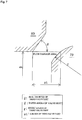
- FIG. 7 is a view showing the factors that determine the flow passage area of the third valve part 79 in FIG. 6 , and shows a state in which the view of FIG. 6 is rotated 90° clockwise.
- the factors determining the flow passage area of the third valve part 79 in Prior Art 1 are the seal diameter D of the third valve part, the taper angle ⁇ of the valve seat, the sphere radius r of the third valve part, and the stroke st of the third valve part.
- the equilibrium of forces on the third valve part 79 is as expressed below in the case that the bellows effective area A and the seal area B of the third seal part are such that A > B.
- the bellows effective diameter and the seal diameter D of the third valve part 79 must be set so as to be the same in order to eliminate dependence on the control chamber pressure Pc.
- the seal diameter D ultimately cannot be changed, due to the limitation placed thereon by the bellows effective diameter.
- Prior Art 2 is capable of accelerating drainage of the liquid refrigerant, but during operation, the control chamber (crankcase) and the suction chamber are always communicated. A flow from the control chamber (crankcase) to the suction chamber therefore occurs, which adversely affects the swash plate control speed during control of the variable-capacity compressor.
- the present invention was developed to solve the problems of Prior Art 1 and Prior Art 2 described above, and an object of the present invention is to provide a capacity control valve capable of enhancing the swash plate control speed during normal control (between maximum-capacity operation and minimum-capacity operation) and minimum-capacity operation and of increasing the ability to drain the liquid refrigerant of the control chamber during startup of the variable-capacity compressor, without changing the control valve characteristics of the capacity control valve.
- a capacity control valve in which the open area between the adapter and the third valve part can be increased and the valve-open state can be maintained until the suction pressure decreases further, the ability to drain the liquid refrigerant of the control chamber during starting of a variable-capacity compressor can be increased, and the swash plate control speed can be enhanced during normal control (between maximum-capacity operation and minimum-capacity operation) and minimum-capacity operation, without changing the control valve characteristics of the capacity control valve.
- the capacity control valve according to a second aspect of the present invention is the capacity control valve according to the first aspect, characterized in that the urging means comprises a coil spring.
- the manufacture and urging-force setting of the urging means are facilitated, and the flow of liquid refrigerant is not inhibited by increasing the pitch of the coil.
- the capacity control valve according to a third aspect of the present invention is the capacity control valve according to the first or second aspect, characterized in that the urging means is disposed on an internal peripheral side of the adapter.
- the space inside the adapter can be efficiently utilized, and the adapter and the third valve part can be compactly formed.
- the capacity control valve according to a fourth aspect of the present invention is the capacity control valve according to the first or second aspect, characterized in that the urging means is disposed on an external peripheral side of the adapter.
- the urging means can be easily attached and replaced.
- the present invention has advantageous effects such as those described below.
- a swash plate variable-capacity compressor M is provided with a discharge chamber 11, a control chamber (also referred to as a crankcase) 12, a suction chamber 13, a plurality of cylinders 14, a port 11b communicating the cylinders 14 and the discharge chamber 11 and opened and closed by a discharge valve 11a, a port 13b communicating the cylinders 14 and the suction chamber 13 and opened and closed by a suction valve 13a, a discharge port 11c and suction port 13c connected to an external refrigerant circuit, a communicating passage 15 as a discharge-side passage for communicating the discharge chamber 11 and the control chamber 12, a communicating passage 16 which serves both as the aforementioned discharge-side passage and as a suction-side passage for communicating the control chamber 12 and the suction chamber 13, a casing 10 for demarcating a communicating passage 17 as a suction-side passage and other components, a rotating shaft 20 protruding outward from inside the control chamber (crankcase) 12 and provided so as to be
- the swash plate variable-capacity compressor M is also provided with a communicating passage 18 for directly communicating the control chamber (crankcase) 12 and the suction chamber 13, and a fixed orifice 19 is provided to the communicating passage 18.
- a refrigerant circuit is also connected to the discharge port 11c and suction port 13c in the swash plate variable-capacity compressor M, and a condenser 25, an expansion valve 26, and an evaporator 27 are arranged in this order in the refrigerant circuit.
- the capacity control valve V is provided with a body 30 formed of a metal material or resin material; a valve body 40 disposed in the body 30 so as to be able to reciprocate; a pressure-sensitive body 50 for urging the valve body 40 in one direction; a solenoid 60 for exerting an electromagnetic driving force on the valve body 40, the solenoid 60 being connected to the body 30; and other components.
- the solenoid 60 is provided with a casing 62 connected to the body 30; a sleeve 63, one end of which is closed; a cylindrical fixed iron core 64 disposed inside the casing 62 and sleeve 63; a driving rod 65 forming a communicating passage 44, a distal end of the driving rod 65 being connected to the valve body 40, and the driving rod 65 being able to reciprocate inside the fixed iron core 64; a movable iron core 66 attached to the other end of the driving rod 65; a coil spring 67 for urging the movable iron core 66 in the direction of opening a first valve part 41; an excitation coil 68 coiled on the outside of the sleeve 63 via a bobbin; and other components.
- the body 30 is provided with communicating passages 31, 32, 33 which function as discharge-side passages, communicating passages 33, 34 which function as suction-side passages together with the communicating passage 44 of the valve body 40 described hereinafter, a first valve chamber 35 formed partway in a discharge-side passage, a second valve chamber 36 formed partway in a suction-side passage, a guide passage 37 for guiding the valve body 40, a third valve chamber 38 formed close to the control chamber 12 in the discharge-side passage and suction-side passage, and other components.
- a blocking member 39 demarcating the third valve chamber 38 and constituting a portion of the body 30 is screwed into and attached to the body 30.
- the communicating passage 33 and the third valve chamber 38 are formed so as to serve as a portion of both a discharge-side passage and a suction-side passage, and the communicating passage 32 communicates the first valve chamber 35 and the third valve chamber 38 and forms a valve hole through the valve body 40 (passing through the valve body 40 while maintaining a gap for fluid flow).
- a plurality (e.g., four spaced 90 degrees apart) of each of the communicating passages 31, 33, 34 is formed in the peripheral direction and radially arranged.
- the valve body 40 is formed in a substantially cylindrical shape and provided with the first valve part 41 at one end thereof and with the second valve part 42 at the other end thereof, a third valve part 43 connected by retrofitting to the opposite side of the valve body 40 from the second valve part 42 so as to sandwich the first valve part 41, a communicating passage 44 penetrating from the second valve part 42 to the third valve part 43 in the axial direction and functioning as a suction-side passage, and other components.
- the third valve part 43 passes through the communicating passage (valve hole) 32 and is formed so as to broaden toward the end from a small-diameter state from the first valve chamber 35 to the third valve chamber 38, and an annular engaging surface 43a which faces an adapter 53 described hereinafter is provided to an external peripheral edge of the third valve part 43 (see also FIG. 3 ).
- the engaging surface 43a of the third valve part 43 for engaging with the adapter 53 is formed as an outwardly concave spherical surface having a curvature radius R, and an end surface 47 as the installation surface for an urging means 48 described hereinafter is formed having a flat shape.
- the pressure-sensitive body 50 is provided with a bellows 51, the adapter 53, and other components.
- One end of the bellows 51 is fixed to the blocking member 39, and the adapter 53 is held at the other end (the free end) thereof.
- the adapter 53 has a hollow cylindrical part 53a substantially bracket-shaped in cross-section, a distal end of which engages with the third valve part 43, and a swelling part 53c which swells inside the bellows 51, and an annular seat surface 53b which engages and disengages with the opposing engaging surface 43a of the third valve part 43 is provided at a distal end of the hollow cylindrical part 53a.
- the seat surface 53b of the hollow cylindrical part 53a is formed as a tapered surface.
- a basal inside surface 53d of the hollow cylindrical part 53a is substantially flat.
- the pressure-sensitive body 50 is disposed inside the third valve chamber 38, and operates so as to exert an urging force in the direction of closing the first valve part 41 when extended (expanded), and to contract in conjunction with a pressure increase on the periphery thereof (in the third valve chamber 38 and the communicating passage 44 of the valve body 40) such that the urging force on the first valve part 41 is reduced.
- FIG. 3 is a sectional enlarged view showing the relevant parts of the capacity control valve of the first embodiment, and describes the equilibrium of forces when the third valve part is stroked.
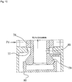
- the urging means 48 operating in the direction of opening the third valve part 43 and the adapter 53 is provided between the end surface 47 of the third valve part 43 and the basal inside surface 53d of the hollow cylindrical part 53a of the adapter 53.
- the urging means 48 is composed of a coil spring or other spring means, and a plurality thereof is arranged at equal intervals in the circumferential direction. In this case, since the coil spring is positioned in the path of drainage of liquid refrigerant, the pitch of the coil is preferably set to a large value.
- variable-capacity compressor When the variable-capacity compressor is left stopped for a long time in the state in which the communicating passages (suction-side passages) 34, 44 are blocked, a state occurs in which liquid refrigerant is accumulated in the control chamber (crankcase) 12 of the variable-capacity compressor, the pressure becomes uniform inside the variable-capacity compressor, and the control chamber pressure Pc becomes significantly higher than the suction pressure Ps and the control chamber pressure Pc that occurs during driving of the variable-capacity compressor.
- the electromagnetic driving force (urging force) of the solenoid 60 acting in the opposite direction from the urging force of the pressure-sensitive body 50 and the coil spring 67 causes the valve body 40 to move toward the bottom in FIG. 2 , and the first valve part 41 is seated on the seat surface 35a to block the communicating passages (discharge-side passages) 31, 32, whereupon the second valve part 42 separates from the 36a and opens the communicating passages (suction-side passages) 34, 44.
- the liquid refrigerant in the control chamber is drained immediately after this startup process, but because the control chamber pressure Pc is at or above a predetermined level, the bellows 51 contracts, the adapter 53 disengages from the third valve part 43, and the suction-side passages (33, 44, 34) are placed in the open state.
- the liquid refrigerant or the like accumulated in the control chamber 12 is drained to the suction chamber 13 through the communicating passages (suction-side passages) 33, 44, 34.
- the size of the drainage passage for the liquid refrigerant or the like is equal to the sum of the open area s1 of the fixed orifice 19 and the open area s2 between the engaging surface 43a of the third valve part 43 and the seat surface 53b of the adapter 53, but because the open area s2 is larger than that of Prior Art 1 by the amount obtained through the valve-opening force of the urging means 48, an adequately large drainage passage area can be maintained.
- FIG. 4 is a view showing the state of the opening in the third valve part.
- the suction pressure Ps is indicated on the horizontal axis
- the open area of the third valve part is indicated on the vertical axis
- the left side of the Ps control range MAX is the normal operating region.
- the spring force of the urging means 48 is set so that the third valve part is closed at a pressure a safe width ⁇ higher than the normal control region, so as to ensure that the control speed during normal control does not decrease.
- the open area s2 of the third valve part 43 is larger than that of Prior Art 1 by the amount obtained through the valve-opening force Fspr2.
- the swash plate 21 rotates integrally with the rotating shaft 20.
- the pistons 22 reciprocate in the cylinders 14 with a stroke that is in accordance with the inclination angle of the swash plate 21, and refrigerant gas taken into the cylinders 14 from the suction chamber 13 is compressed by the pistons 22 and discharged to the discharge chamber 11.
- the discharged refrigerant gas is fed to the evaporator 27 from the condenser 25 through the expansion valve 26 and returned to the suction chamber 13 as the refrigeration cycle is performed.
- the discharge amount of refrigerant gas in this instance is determined by the stroke of the pistons 22, and the stroke of the pistons 22 is determined by the inclination angle of the swash plate 21 controlled by the pressure (control chamber pressure Pc) inside the control chamber 12.
- blow-by gas from the clearance between the pistons 22 and the cylinders 14 continuously flows toward the control chamber 12 and acts to increase the pressure Pc of the control chamber 12.
- the fixed orifice 19 since the fixed orifice 19 is provided, a certain amount of pressure is released to the suction chamber from the control chamber 12 even when the communicating passages (suction-side passages) 33, 44, 34 are closed, and the appropriate pressure can be maintained in the control chamber 12.
- the pressure-sensitive body 50 When draining of the liquid refrigerant in the control chamber 12 is completed and the control chamber pressure Pc decreases to or below a predetermined level, the pressure-sensitive body 50 extends by elastic return, and the adapter 53 engages with the third valve part 43 to close the valve.
- the solenoid 60 (coil 68) is supplied with current at a predetermined current value (I)
- the movable iron core 66 and the driving rod 65 resist the urging force of the pressure-sensitive body 50 and the coil spring 67
- the valve body 40 moves to a position at which a state occurs in which the first valve part 41 is seated on the seat surface 35a to block the communicating passages (discharge-side passages) 31, 32, and the second valve part 42 is separated from the seat surface 36a to open the communicating passages (suction-side passages) 34, 44.
- the amount of power supplied to the solenoid 60 (coil 67) is appropriately controlled to vary the electromagnetic driving force (urging force) thereof.
- the position of the valve body 40 is appropriately adjusted by the electromagnetic driving force, and the opening amount of the first valve part 41 and the opening amount of the second valve part 42 are controlled to achieve the desired discharge amount.
- the third valve part 43 is closed in this state.
- the open area of the communicating passages (33, 44, 34) can be made about as small as that of the fixed orifice, and the communicating passages (33, 44, 34) can be blocked during minimum-capacity operation, it is possible to increase the swash plate control speed during normal control and minimum-capacity operation.
- FIG. 5 is a sectional front view showing a second embodiment of the capacity control valve of the present invention.
- FIG. 5 reference numerals that are the same as those in FIG. 2 refer to the same members, and no detailed description of such members is given hereinafter.
- a flange 45 extending through the entire circumference is provided on an outside surface positioned closer to the solenoid 60 than the end surface 47 of the third valve part 43, and a flange 54 extending through the entire circumference is also provided in the adapter 53 on a basal outside surface of the hollow cylindrical part 53a.
- the urging means 48 is installed between the flange 45 of the third valve part 43 and the flange 54 of the adapter 53, along the external periphery of the hollow cylindrical part 53a of the adapter 53, and acts in the valve-opening direction of the third valve part 43 and the adapter 53.
- the urging means 48 comprises a coil spring or other spring means, and a plurality thereof is arranged at equal intervals in the circumferential direction.
- the pitch of the coil is preferably set to a large value.
Landscapes
- Engineering & Computer Science (AREA)
- Mechanical Engineering (AREA)
- General Engineering & Computer Science (AREA)
- Physics & Mathematics (AREA)
- Thermal Sciences (AREA)
- Compressors, Vaccum Pumps And Other Relevant Systems (AREA)
- Control Of Positive-Displacement Pumps (AREA)
Claims (4)
- Soupape de commande de capacité (V) comprenant :un passage côté évacuation (31, 32) pour faire communiquer une chambre d'évacuation (11) pour évacuer un fluide et une chambre de contrôle (12) pour contrôler une quantité de fluide évacuée ;une première chambre de soupape (35) formée en partie dans ledit passage côté décharge (31, 32) ;un passage côté aspiration (34) pour faire communiquer ladite chambre de contrôle (12) et une chambre d'aspiration (13) pour aspirer du fluide ;une deuxième chambre de soupape (36) formée en partie dans ledit passage côté aspiration (34) ;un corps de soupape (40) ayant de manière intégrée une première partie de soupape (41) pour ouvrir et fermer ledit passage côté évacuation (31, 32) dans ladite première chambre de soupape (35) et une deuxième partie de soupape (42) pour ouvrir et fermer ledit passage côté aspiration (34) dans ladite deuxième chambre de soupape (36), la première partie de soupape (41) et la deuxième partie de soupape (42) s'ouvrant et se fermant alternativement l'une par rapport à l'autre par un mouvement de va-et-vient ;une troisième chambre de soupape (38) formée en partie dans ledit passage côté aspiration (34) plus proche de ladite chambre de contrôle (12) que de ladite deuxième chambre de soupape (36) ;un corps sensible à la pression (50) pour exercer une force de poussée dans la direction d'ouverture de ladite première partie de soupape (35) par extension du corps sensible à la pression (50) et par contraction en même temps qu'une augmentation de la pression ambiante, le corps sensible à la pression (50) étant disposé dans ladite troisième chambre de soupape (38);un adaptateur (53) prévu sur une extrémité libre dudit corps sensible à la pression (50) dans sa direction d'extension et de contraction et ayant une surface de siège annulaire (53b) ;une troisième partie de soupape (43) ayant une surface de mise en prise annulaire (43a) pour se déplacer d'un seul tenant avec ledit corps de soupape (40) dans ladite troisième chambre de soupape (38) et pour ouvrir et fermer ledit passage côté aspiration (34) par mise en prise et libération de la surface de siège (53b) dudit adaptateur (53) ; etun solénoïde (60) pour exercer une force d'entraînement électromagnétique sur le corps de soupape (40) dans la direction de fermeture de la première partie de soupape (41), caractérisé en ce quedes moyens de poussée (48) sont prévus pour agir dans la direction d'ouverture de soupape entre ledit adaptateur (53) et la troisième partie de soupape (43).
- Soupape de commande de capacité (V) selon la revendication 1, caractérisée en ce que les moyens de poussée (48) comprennent un ressort hélicoïdal (67).
- Soupape de commande de capacité (V) selon la revendication 1 ou 2, caractérisée en ce que les moyens de poussée (48) sont disposés sur un côté périphérique interne dudit adaptateur (53).
- Soupape de commande de capacité (V) selon la revendication 1 ou 2, caractérisée en ce que les moyens de poussée (48) sont disposés sur un côté périphérique externe dudit adaptateur (53).
Applications Claiming Priority (2)
| Application Number | Priority Date | Filing Date | Title |
|---|---|---|---|
| JP2010274162 | 2010-12-09 | ||
| PCT/JP2011/075460 WO2012077439A1 (fr) | 2010-12-09 | 2011-11-04 | Soupape de commande de capacité |
Publications (3)
| Publication Number | Publication Date |
|---|---|
| EP2653723A1 EP2653723A1 (fr) | 2013-10-23 |
| EP2653723A4 EP2653723A4 (fr) | 2018-01-24 |
| EP2653723B1 true EP2653723B1 (fr) | 2019-01-02 |
Family
ID=46206941
Family Applications (1)
| Application Number | Title | Priority Date | Filing Date |
|---|---|---|---|
| EP11846740.6A Active EP2653723B1 (fr) | 2010-12-09 | 2011-11-04 | Soupape de commande de capacité |
Country Status (6)
| Country | Link |
|---|---|
| US (1) | US9132714B2 (fr) |
| EP (1) | EP2653723B1 (fr) |
| JP (1) | JP5871281B2 (fr) |
| KR (1) | KR101375294B1 (fr) |
| CN (1) | CN103237986B (fr) |
| WO (1) | WO2012077439A1 (fr) |
Families Citing this family (56)
| Publication number | Priority date | Publication date | Assignee | Title |
|---|---|---|---|---|
| JP6091503B2 (ja) * | 2012-05-24 | 2017-03-08 | イーグル工業株式会社 | 容量制御弁 |
| JP6064131B2 (ja) * | 2012-10-17 | 2017-01-25 | 株式会社テージーケー | 可変容量圧縮機用制御弁 |
| KR101689241B1 (ko) * | 2012-12-12 | 2016-12-23 | 이구루코교 가부시기가이샤 | 용량 제어 밸브 |
| EP2952741B1 (fr) * | 2013-01-31 | 2019-03-13 | Eagle Industry Co., Ltd. | Compresseur à capacité variable |
| JP6136461B2 (ja) * | 2013-03-29 | 2017-05-31 | 株式会社豊田自動織機 | 可変容量型圧縮機 |
| JP6149239B2 (ja) * | 2013-06-28 | 2017-06-21 | 株式会社テージーケー | 可変容量圧縮機用制御弁 |
| CN107148527B (zh) * | 2014-11-25 | 2019-03-19 | 伊格尔工业股份有限公司 | 容量控制阀 |
| CN107489791B (zh) | 2016-06-13 | 2020-12-04 | 株式会社Tgk | 可变容量压缩机用控制阀 |
| WO2018043186A1 (fr) * | 2016-08-29 | 2018-03-08 | イーグル工業株式会社 | Vanne de commande de capacité |
| JP6632503B2 (ja) * | 2016-09-30 | 2020-01-22 | 株式会社不二工機 | 可変容量型圧縮機用制御弁 |
| EP3575647B1 (fr) * | 2017-01-26 | 2022-11-30 | Eagle Industry Co., Ltd. | Soupape de commande de capacité |
| US11542930B2 (en) | 2017-02-18 | 2023-01-03 | Eagle Industry Co., Ltd. | Capacity control valve |
| EP3604806B1 (fr) | 2017-03-28 | 2022-05-25 | Eagle Industry Co., Ltd. | Soupape de commande de capacité |
| JP6997536B2 (ja) * | 2017-05-09 | 2022-01-17 | サンデン・オートモーティブコンポーネント株式会社 | ソレノイド制御弁及びこれを備えた可変容量圧縮機 |
| EP3677820B1 (fr) | 2017-08-28 | 2025-07-16 | Eagle Industry Co., Ltd. | Soupape électromagnétique |
| US11542931B2 (en) | 2017-11-15 | 2023-01-03 | Eagle Industry Co., Ltd. | Capacity control valve and capacity control valve control method |
| CN107975470A (zh) * | 2017-11-27 | 2018-05-01 | 山西中航锦恒科技有限公司 | 一种内部带节流装置的电动控制阀 |
| US11512786B2 (en) | 2017-11-30 | 2022-11-29 | Eagle Industry Co., Ltd. | Capacity control valve and control method for capacity control valve |
| US11519399B2 (en) | 2017-12-08 | 2022-12-06 | Eagle Industry Co., Ltd. | Capacity control valve and method for controlling same |
| CN111417780B (zh) | 2017-12-14 | 2022-05-17 | 伊格尔工业股份有限公司 | 容量控制阀及容量控制阀的控制方法 |
| WO2019131693A1 (fr) * | 2017-12-27 | 2019-07-04 | イーグル工業株式会社 | Soupape de régulation de capacité et procédé de régulation associé |
| JP7114203B2 (ja) * | 2017-12-27 | 2022-08-08 | イーグル工業株式会社 | 容量制御弁 |
| US11486376B2 (en) | 2017-12-27 | 2022-11-01 | Eagle Industry Co., Ltd. | Capacity control valve and method for controlling same |
| WO2019142931A1 (fr) | 2018-01-22 | 2019-07-25 | イーグル工業株式会社 | Soupape de commande de capacité |
| JP7167067B2 (ja) | 2018-01-26 | 2022-11-08 | イーグル工業株式会社 | 容量制御弁 |
| CN111684157B (zh) | 2018-02-15 | 2022-05-03 | 伊格尔工业股份有限公司 | 容量控制阀 |
| US11401923B2 (en) | 2018-02-15 | 2022-08-02 | Eagle Industry Co., Ltd. | Capacity control valve |
| US11873804B2 (en) | 2018-02-27 | 2024-01-16 | Eagle Industry Co., Ltd. | Capacity control valve |
| US11225962B2 (en) * | 2018-05-23 | 2022-01-18 | Eagle Industry Co., Ltd. | Capacity control valve |
| WO2020013156A1 (fr) | 2018-07-12 | 2020-01-16 | イーグル工業株式会社 | Vanne de contröle de capacité |
| JP7289603B2 (ja) | 2018-08-08 | 2023-06-12 | イーグル工業株式会社 | 容量制御弁 |
| WO2020032087A1 (fr) | 2018-08-08 | 2020-02-13 | イーグル工業株式会社 | Soupape de régulation de capacité |
| KR102541900B1 (ko) | 2018-11-26 | 2023-06-13 | 이구루코교 가부시기가이샤 | 용량 제어 밸브 |
| DE102018132448A1 (de) * | 2018-12-17 | 2020-06-18 | ECO Holding 1 GmbH | Expansionsventil für Kältemittel und Klimaanlage, Wärmemanagementsystem und Batteriekühlsystem mit einem Expansionsventil |
| JP7423165B2 (ja) * | 2019-01-21 | 2024-01-29 | イーグル工業株式会社 | 容量制御弁 |
| WO2020204135A1 (fr) * | 2019-04-03 | 2020-10-08 | イーグル工業株式会社 | Soupape de commande de capacité |
| KR102744357B1 (ko) | 2019-04-03 | 2024-12-18 | 이구루코교 가부시기가이샤 | 용량 제어 밸브 |
| CN113646529A (zh) | 2019-04-03 | 2021-11-12 | 伊格尔工业股份有限公司 | 容量控制阀 |
| CN113661324B (zh) | 2019-04-03 | 2023-06-06 | 伊格尔工业股份有限公司 | 容量控制阀 |
| WO2020204134A1 (fr) | 2019-04-03 | 2020-10-08 | イーグル工業株式会社 | Soupape de régulation de capacité |
| KR102634942B1 (ko) | 2019-04-24 | 2024-02-08 | 이구루코교 가부시기가이샤 | 용량 제어 밸브 |
| CN113692491B (zh) * | 2019-04-24 | 2023-07-04 | 伊格尔工业股份有限公司 | 容量控制阀 |
| US12270476B2 (en) | 2020-04-22 | 2025-04-08 | Eagle Industry Co., Ltd. | Capacity control valve |
| EP4141259B1 (fr) | 2020-04-23 | 2025-10-01 | Eagle Industry Co., Ltd. | Vanne de régulation de capacité |
| JPWO2022030309A1 (fr) | 2020-08-03 | 2022-02-10 | ||
| US12298048B2 (en) | 2020-08-04 | 2025-05-13 | Eagle Industry Co., Ltd. | Expansion valve |
| JP7673070B2 (ja) | 2020-08-04 | 2025-05-08 | イーグル工業株式会社 | 弁 |
| CN116134254B (zh) | 2020-08-04 | 2025-11-07 | 伊格尔工业股份有限公司 | 阀 |
| CN116097026B (zh) | 2020-08-24 | 2025-11-11 | 伊格尔工业股份有限公司 | 阀 |
| US12264744B2 (en) | 2020-09-28 | 2025-04-01 | Eagle Industry Co., Ltd. | Valve |
| CN116457592A (zh) | 2020-10-01 | 2023-07-18 | 伊格尔工业股份有限公司 | 阀 |
| JP7631361B2 (ja) | 2020-10-01 | 2025-02-18 | イーグル工業株式会社 | 流体制御弁 |
| KR102785818B1 (ko) | 2020-12-17 | 2025-03-26 | 이구루코교 가부시기가이샤 | 밸브 |
| JP7780506B2 (ja) | 2021-03-29 | 2025-12-04 | イーグル工業株式会社 | 弁 |
| WO2022255188A1 (fr) | 2021-05-31 | 2022-12-08 | イーグル工業株式会社 | Vanne de régulation de fluide |
| CN117881912A (zh) | 2021-09-02 | 2024-04-12 | 伊格尔工业股份有限公司 | 流体控制阀 |
Family Cites Families (13)
| Publication number | Priority date | Publication date | Assignee | Title |
|---|---|---|---|---|
| JP3984724B2 (ja) * | 1998-09-10 | 2007-10-03 | 株式会社豊田自動織機 | 容量可変型斜板式圧縮機の制御弁及び斜板式圧縮機 |
| JP3583951B2 (ja) * | 1999-06-07 | 2004-11-04 | 株式会社豊田自動織機 | 容量制御弁 |
| JP4246975B2 (ja) * | 2002-02-04 | 2009-04-02 | イーグル工業株式会社 | 容量制御弁 |
| JP4046530B2 (ja) | 2002-03-26 | 2008-02-13 | 株式会社テージーケー | 可変容量圧縮機用容量制御弁 |
| JP4118587B2 (ja) * | 2002-04-09 | 2008-07-16 | サンデン株式会社 | 可変容量圧縮機 |
| US6939112B2 (en) * | 2002-04-25 | 2005-09-06 | Sanden Corporation | Variable displacement compressors |
| JP2005098197A (ja) * | 2003-09-04 | 2005-04-14 | Tgk Co Ltd | 可変容量圧縮機用容量制御弁 |
| JP4331667B2 (ja) | 2004-10-22 | 2009-09-16 | 株式会社テージーケー | 可変容量圧縮機用制御弁 |
| JP2006194114A (ja) * | 2005-01-12 | 2006-07-27 | Tgk Co Ltd | 可変容量圧縮機用制御弁 |
| CN100516516C (zh) | 2005-02-24 | 2009-07-22 | 株式会社丰田自动织机 | 容量控制阀 |
| JP4504243B2 (ja) * | 2005-04-12 | 2010-07-14 | 株式会社不二工機 | 可変容量型圧縮機用制御弁 |
| CN101410620B (zh) | 2006-03-15 | 2011-03-23 | 伊格尔工业股份有限公司 | 容量控制阀 |
| WO2011114841A1 (fr) * | 2010-03-16 | 2011-09-22 | イーグル工業株式会社 | Soupape de commande de volume |
-
2011
- 2011-11-04 US US13/816,626 patent/US9132714B2/en active Active
- 2011-11-04 EP EP11846740.6A patent/EP2653723B1/fr active Active
- 2011-11-04 KR KR1020137009941A patent/KR101375294B1/ko active Active
- 2011-11-04 JP JP2012547748A patent/JP5871281B2/ja active Active
- 2011-11-04 CN CN201180057901.9A patent/CN103237986B/zh active Active
- 2011-11-04 WO PCT/JP2011/075460 patent/WO2012077439A1/fr not_active Ceased
Non-Patent Citations (1)
| Title |
|---|
| None * |
Also Published As
| Publication number | Publication date |
|---|---|
| JP5871281B2 (ja) | 2016-03-01 |
| JPWO2012077439A1 (ja) | 2014-05-19 |
| KR101375294B1 (ko) | 2014-03-17 |
| EP2653723A1 (fr) | 2013-10-23 |
| CN103237986B (zh) | 2015-09-30 |
| WO2012077439A1 (fr) | 2012-06-14 |
| KR20130056349A (ko) | 2013-05-29 |
| US9132714B2 (en) | 2015-09-15 |
| CN103237986A (zh) | 2013-08-07 |
| US20130291963A1 (en) | 2013-11-07 |
| EP2653723A4 (fr) | 2018-01-24 |
Similar Documents
| Publication | Publication Date | Title |
|---|---|---|
| US9132714B2 (en) | Capacity control valve | |
| EP2549106B1 (fr) | Soupape de commande de volume | |
| JP4700048B2 (ja) | 容量制御弁 | |
| EP3339643B1 (fr) | Soupape de commande pour compresseur à déplacement variable | |
| EP2722524B1 (fr) | Soupape de réglage de la capacité | |
| EP2952741B1 (fr) | Compresseur à capacité variable | |
| EP2933487B1 (fr) | Soupape de commande de capacité | |
| EP2565452B1 (fr) | Soupape à commande de capacité | |
| JP4431462B2 (ja) | 斜板式容量可変型圧縮機および電磁制御弁 | |
| JP6626790B2 (ja) | 可変容量型圧縮機用制御弁 | |
| EP3604806B1 (fr) | Soupape de commande de capacité |
Legal Events
| Date | Code | Title | Description |
|---|---|---|---|
| PUAI | Public reference made under article 153(3) epc to a published international application that has entered the european phase |
Free format text: ORIGINAL CODE: 0009012 |
|
| 17P | Request for examination filed |
Effective date: 20130429 |
|
| AK | Designated contracting states |
Kind code of ref document: A1 Designated state(s): AL AT BE BG CH CY CZ DE DK EE ES FI FR GB GR HR HU IE IS IT LI LT LU LV MC MK MT NL NO PL PT RO RS SE SI SK SM TR |
|
| DAX | Request for extension of the european patent (deleted) | ||
| RA4 | Supplementary search report drawn up and despatched (corrected) |
Effective date: 20180104 |
|
| RIC1 | Information provided on ipc code assigned before grant |
Ipc: F04B 27/14 20060101AFI20171221BHEP Ipc: B60H 1/00 20060101ALI20171221BHEP Ipc: F04B 27/18 20060101ALI20171221BHEP |
|
| RIC1 | Information provided on ipc code assigned before grant |
Ipc: B60H 1/00 20060101ALI20180607BHEP Ipc: F04B 27/14 20060101AFI20180607BHEP Ipc: F04B 27/18 20060101ALI20180607BHEP |
|
| GRAP | Despatch of communication of intention to grant a patent |
Free format text: ORIGINAL CODE: EPIDOSNIGR1 |
|
| STAA | Information on the status of an ep patent application or granted ep patent |
Free format text: STATUS: GRANT OF PATENT IS INTENDED |
|
| INTG | Intention to grant announced |
Effective date: 20180802 |
|
| GRAS | Grant fee paid |
Free format text: ORIGINAL CODE: EPIDOSNIGR3 |
|
| GRAA | (expected) grant |
Free format text: ORIGINAL CODE: 0009210 |
|
| STAA | Information on the status of an ep patent application or granted ep patent |
Free format text: STATUS: THE PATENT HAS BEEN GRANTED |
|
| AK | Designated contracting states |
Kind code of ref document: B1 Designated state(s): AL AT BE BG CH CY CZ DE DK EE ES FI FR GB GR HR HU IE IS IT LI LT LU LV MC MK MT NL NO PL PT RO RS SE SI SK SM TR |
|
| REG | Reference to a national code |
Ref country code: GB Ref legal event code: FG4D |
|
| REG | Reference to a national code |
Ref country code: CH Ref legal event code: EP Ref country code: AT Ref legal event code: REF Ref document number: 1084719 Country of ref document: AT Kind code of ref document: T Effective date: 20190115 |
|
| REG | Reference to a national code |
Ref country code: IE Ref legal event code: FG4D |
|
| REG | Reference to a national code |
Ref country code: DE Ref legal event code: R096 Ref document number: 602011055461 Country of ref document: DE |
|
| REG | Reference to a national code |
Ref country code: NL Ref legal event code: MP Effective date: 20190102 |
|
| REG | Reference to a national code |
Ref country code: LT Ref legal event code: MG4D |
|
| REG | Reference to a national code |
Ref country code: AT Ref legal event code: MK05 Ref document number: 1084719 Country of ref document: AT Kind code of ref document: T Effective date: 20190102 |
|
| PG25 | Lapsed in a contracting state [announced via postgrant information from national office to epo] |
Ref country code: NL Free format text: LAPSE BECAUSE OF FAILURE TO SUBMIT A TRANSLATION OF THE DESCRIPTION OR TO PAY THE FEE WITHIN THE PRESCRIBED TIME-LIMIT Effective date: 20190102 |
|
| PG25 | Lapsed in a contracting state [announced via postgrant information from national office to epo] |
Ref country code: NO Free format text: LAPSE BECAUSE OF FAILURE TO SUBMIT A TRANSLATION OF THE DESCRIPTION OR TO PAY THE FEE WITHIN THE PRESCRIBED TIME-LIMIT Effective date: 20190402 Ref country code: LT Free format text: LAPSE BECAUSE OF FAILURE TO SUBMIT A TRANSLATION OF THE DESCRIPTION OR TO PAY THE FEE WITHIN THE PRESCRIBED TIME-LIMIT Effective date: 20190102 Ref country code: FI Free format text: LAPSE BECAUSE OF FAILURE TO SUBMIT A TRANSLATION OF THE DESCRIPTION OR TO PAY THE FEE WITHIN THE PRESCRIBED TIME-LIMIT Effective date: 20190102 Ref country code: PL Free format text: LAPSE BECAUSE OF FAILURE TO SUBMIT A TRANSLATION OF THE DESCRIPTION OR TO PAY THE FEE WITHIN THE PRESCRIBED TIME-LIMIT Effective date: 20190102 Ref country code: SE Free format text: LAPSE BECAUSE OF FAILURE TO SUBMIT A TRANSLATION OF THE DESCRIPTION OR TO PAY THE FEE WITHIN THE PRESCRIBED TIME-LIMIT Effective date: 20190102 Ref country code: PT Free format text: LAPSE BECAUSE OF FAILURE TO SUBMIT A TRANSLATION OF THE DESCRIPTION OR TO PAY THE FEE WITHIN THE PRESCRIBED TIME-LIMIT Effective date: 20190502 Ref country code: ES Free format text: LAPSE BECAUSE OF FAILURE TO SUBMIT A TRANSLATION OF THE DESCRIPTION OR TO PAY THE FEE WITHIN THE PRESCRIBED TIME-LIMIT Effective date: 20190102 |
|
| PG25 | Lapsed in a contracting state [announced via postgrant information from national office to epo] |
Ref country code: LV Free format text: LAPSE BECAUSE OF FAILURE TO SUBMIT A TRANSLATION OF THE DESCRIPTION OR TO PAY THE FEE WITHIN THE PRESCRIBED TIME-LIMIT Effective date: 20190102 Ref country code: RS Free format text: LAPSE BECAUSE OF FAILURE TO SUBMIT A TRANSLATION OF THE DESCRIPTION OR TO PAY THE FEE WITHIN THE PRESCRIBED TIME-LIMIT Effective date: 20190102 Ref country code: BG Free format text: LAPSE BECAUSE OF FAILURE TO SUBMIT A TRANSLATION OF THE DESCRIPTION OR TO PAY THE FEE WITHIN THE PRESCRIBED TIME-LIMIT Effective date: 20190402 Ref country code: HR Free format text: LAPSE BECAUSE OF FAILURE TO SUBMIT A TRANSLATION OF THE DESCRIPTION OR TO PAY THE FEE WITHIN THE PRESCRIBED TIME-LIMIT Effective date: 20190102 Ref country code: GR Free format text: LAPSE BECAUSE OF FAILURE TO SUBMIT A TRANSLATION OF THE DESCRIPTION OR TO PAY THE FEE WITHIN THE PRESCRIBED TIME-LIMIT Effective date: 20190403 Ref country code: IS Free format text: LAPSE BECAUSE OF FAILURE TO SUBMIT A TRANSLATION OF THE DESCRIPTION OR TO PAY THE FEE WITHIN THE PRESCRIBED TIME-LIMIT Effective date: 20190502 |
|
| REG | Reference to a national code |
Ref country code: DE Ref legal event code: R097 Ref document number: 602011055461 Country of ref document: DE |
|
| PG25 | Lapsed in a contracting state [announced via postgrant information from national office to epo] |
Ref country code: AT Free format text: LAPSE BECAUSE OF FAILURE TO SUBMIT A TRANSLATION OF THE DESCRIPTION OR TO PAY THE FEE WITHIN THE PRESCRIBED TIME-LIMIT Effective date: 20190102 Ref country code: DK Free format text: LAPSE BECAUSE OF FAILURE TO SUBMIT A TRANSLATION OF THE DESCRIPTION OR TO PAY THE FEE WITHIN THE PRESCRIBED TIME-LIMIT Effective date: 20190102 Ref country code: EE Free format text: LAPSE BECAUSE OF FAILURE TO SUBMIT A TRANSLATION OF THE DESCRIPTION OR TO PAY THE FEE WITHIN THE PRESCRIBED TIME-LIMIT Effective date: 20190102 Ref country code: AL Free format text: LAPSE BECAUSE OF FAILURE TO SUBMIT A TRANSLATION OF THE DESCRIPTION OR TO PAY THE FEE WITHIN THE PRESCRIBED TIME-LIMIT Effective date: 20190102 Ref country code: CZ Free format text: LAPSE BECAUSE OF FAILURE TO SUBMIT A TRANSLATION OF THE DESCRIPTION OR TO PAY THE FEE WITHIN THE PRESCRIBED TIME-LIMIT Effective date: 20190102 Ref country code: IT Free format text: LAPSE BECAUSE OF FAILURE TO SUBMIT A TRANSLATION OF THE DESCRIPTION OR TO PAY THE FEE WITHIN THE PRESCRIBED TIME-LIMIT Effective date: 20190102 Ref country code: RO Free format text: LAPSE BECAUSE OF FAILURE TO SUBMIT A TRANSLATION OF THE DESCRIPTION OR TO PAY THE FEE WITHIN THE PRESCRIBED TIME-LIMIT Effective date: 20190102 Ref country code: SK Free format text: LAPSE BECAUSE OF FAILURE TO SUBMIT A TRANSLATION OF THE DESCRIPTION OR TO PAY THE FEE WITHIN THE PRESCRIBED TIME-LIMIT Effective date: 20190102 |
|
| PLBE | No opposition filed within time limit |
Free format text: ORIGINAL CODE: 0009261 |
|
| STAA | Information on the status of an ep patent application or granted ep patent |
Free format text: STATUS: NO OPPOSITION FILED WITHIN TIME LIMIT |
|
| PG25 | Lapsed in a contracting state [announced via postgrant information from national office to epo] |
Ref country code: SM Free format text: LAPSE BECAUSE OF FAILURE TO SUBMIT A TRANSLATION OF THE DESCRIPTION OR TO PAY THE FEE WITHIN THE PRESCRIBED TIME-LIMIT Effective date: 20190102 |
|
| 26N | No opposition filed |
Effective date: 20191003 |
|
| PG25 | Lapsed in a contracting state [announced via postgrant information from national office to epo] |
Ref country code: SI Free format text: LAPSE BECAUSE OF FAILURE TO SUBMIT A TRANSLATION OF THE DESCRIPTION OR TO PAY THE FEE WITHIN THE PRESCRIBED TIME-LIMIT Effective date: 20190102 |
|
| PG25 | Lapsed in a contracting state [announced via postgrant information from national office to epo] |
Ref country code: TR Free format text: LAPSE BECAUSE OF FAILURE TO SUBMIT A TRANSLATION OF THE DESCRIPTION OR TO PAY THE FEE WITHIN THE PRESCRIBED TIME-LIMIT Effective date: 20190102 |
|
| REG | Reference to a national code |
Ref country code: CH Ref legal event code: PL |
|
| PG25 | Lapsed in a contracting state [announced via postgrant information from national office to epo] |
Ref country code: LI Free format text: LAPSE BECAUSE OF NON-PAYMENT OF DUE FEES Effective date: 20191130 Ref country code: LU Free format text: LAPSE BECAUSE OF NON-PAYMENT OF DUE FEES Effective date: 20191104 Ref country code: CH Free format text: LAPSE BECAUSE OF NON-PAYMENT OF DUE FEES Effective date: 20191130 Ref country code: MC Free format text: LAPSE BECAUSE OF FAILURE TO SUBMIT A TRANSLATION OF THE DESCRIPTION OR TO PAY THE FEE WITHIN THE PRESCRIBED TIME-LIMIT Effective date: 20190102 |
|
| REG | Reference to a national code |
Ref country code: BE Ref legal event code: MM Effective date: 20191130 |
|
| GBPC | Gb: european patent ceased through non-payment of renewal fee |
Effective date: 20191104 |
|
| PG25 | Lapsed in a contracting state [announced via postgrant information from national office to epo] |
Ref country code: IE Free format text: LAPSE BECAUSE OF NON-PAYMENT OF DUE FEES Effective date: 20191104 Ref country code: GB Free format text: LAPSE BECAUSE OF NON-PAYMENT OF DUE FEES Effective date: 20191104 |
|
| PG25 | Lapsed in a contracting state [announced via postgrant information from national office to epo] |
Ref country code: BE Free format text: LAPSE BECAUSE OF NON-PAYMENT OF DUE FEES Effective date: 20191130 |
|
| PG25 | Lapsed in a contracting state [announced via postgrant information from national office to epo] |
Ref country code: CY Free format text: LAPSE BECAUSE OF FAILURE TO SUBMIT A TRANSLATION OF THE DESCRIPTION OR TO PAY THE FEE WITHIN THE PRESCRIBED TIME-LIMIT Effective date: 20190102 |
|
| PG25 | Lapsed in a contracting state [announced via postgrant information from national office to epo] |
Ref country code: HU Free format text: LAPSE BECAUSE OF FAILURE TO SUBMIT A TRANSLATION OF THE DESCRIPTION OR TO PAY THE FEE WITHIN THE PRESCRIBED TIME-LIMIT; INVALID AB INITIO Effective date: 20111104 Ref country code: MT Free format text: LAPSE BECAUSE OF FAILURE TO SUBMIT A TRANSLATION OF THE DESCRIPTION OR TO PAY THE FEE WITHIN THE PRESCRIBED TIME-LIMIT Effective date: 20190102 |
|
| PG25 | Lapsed in a contracting state [announced via postgrant information from national office to epo] |
Ref country code: MK Free format text: LAPSE BECAUSE OF FAILURE TO SUBMIT A TRANSLATION OF THE DESCRIPTION OR TO PAY THE FEE WITHIN THE PRESCRIBED TIME-LIMIT Effective date: 20190102 |
|
| PGFP | Annual fee paid to national office [announced via postgrant information from national office to epo] |
Ref country code: FR Payment date: 20250930 Year of fee payment: 15 |
|
| PGFP | Annual fee paid to national office [announced via postgrant information from national office to epo] |
Ref country code: DE Payment date: 20250930 Year of fee payment: 15 |