EP2653725B1 - Appareil permettant de commander le démarrage et l'arrêt d'une pompe d'un réseau de distribution d'eau - Google Patents
Appareil permettant de commander le démarrage et l'arrêt d'une pompe d'un réseau de distribution d'eau Download PDFInfo
- Publication number
- EP2653725B1 EP2653725B1 EP13164394.2A EP13164394A EP2653725B1 EP 2653725 B1 EP2653725 B1 EP 2653725B1 EP 13164394 A EP13164394 A EP 13164394A EP 2653725 B1 EP2653725 B1 EP 2653725B1
- Authority
- EP
- European Patent Office
- Prior art keywords
- magnetic field
- pressure
- value
- chamber
- pump
- Prior art date
- Legal status (The legal status is an assumption and is not a legal conclusion. Google has not performed a legal analysis and makes no representation as to the accuracy of the status listed.)
- Active
Links
Images


Classifications
-
- F—MECHANICAL ENGINEERING; LIGHTING; HEATING; WEAPONS; BLASTING
- F04—POSITIVE - DISPLACEMENT MACHINES FOR LIQUIDS; PUMPS FOR LIQUIDS OR ELASTIC FLUIDS
- F04B—POSITIVE-DISPLACEMENT MACHINES FOR LIQUIDS; PUMPS
- F04B49/00—Control, e.g. of pump delivery, or pump pressure of, or safety measures for, machines, pumps, or pumping installations, not otherwise provided for, or of interest apart from, groups F04B1/00 - F04B47/00
- F04B49/02—Stopping, starting, unloading or idling control
- F04B49/022—Stopping, starting, unloading or idling control by means of pressure
-
- F—MECHANICAL ENGINEERING; LIGHTING; HEATING; WEAPONS; BLASTING
- F04—POSITIVE - DISPLACEMENT MACHINES FOR LIQUIDS; PUMPS FOR LIQUIDS OR ELASTIC FLUIDS
- F04B—POSITIVE-DISPLACEMENT MACHINES FOR LIQUIDS; PUMPS
- F04B49/00—Control, e.g. of pump delivery, or pump pressure of, or safety measures for, machines, pumps, or pumping installations, not otherwise provided for, or of interest apart from, groups F04B1/00 - F04B47/00
- F04B49/06—Control using electricity
- F04B49/065—Control using electricity and making use of computers
-
- F—MECHANICAL ENGINEERING; LIGHTING; HEATING; WEAPONS; BLASTING
- F04—POSITIVE - DISPLACEMENT MACHINES FOR LIQUIDS; PUMPS FOR LIQUIDS OR ELASTIC FLUIDS
- F04B—POSITIVE-DISPLACEMENT MACHINES FOR LIQUIDS; PUMPS
- F04B49/00—Control, e.g. of pump delivery, or pump pressure of, or safety measures for, machines, pumps, or pumping installations, not otherwise provided for, or of interest apart from, groups F04B1/00 - F04B47/00
- F04B49/08—Regulating by delivery pressure
-
- F—MECHANICAL ENGINEERING; LIGHTING; HEATING; WEAPONS; BLASTING
- F04—POSITIVE - DISPLACEMENT MACHINES FOR LIQUIDS; PUMPS FOR LIQUIDS OR ELASTIC FLUIDS
- F04D—NON-POSITIVE-DISPLACEMENT PUMPS
- F04D15/00—Control, e.g. regulation, of pumps, pumping installations or systems
- F04D15/02—Stopping of pumps, or operating valves, on occurrence of unwanted conditions
- F04D15/0209—Stopping of pumps, or operating valves, on occurrence of unwanted conditions responsive to a condition of the working fluid
-
- H—ELECTRICITY
- H01—ELECTRIC ELEMENTS
- H01H—ELECTRIC SWITCHES; RELAYS; SELECTORS; EMERGENCY PROTECTIVE DEVICES
- H01H35/00—Switches operated by change of a physical condition
- H01H35/02—Switches operated by change of position, inclination or orientation of the switch itself in relation to gravitational field
- H01H35/022—Switches operated by change of position, inclination or orientation of the switch itself in relation to gravitational field the switch being of the reed switch type
-
- H—ELECTRICITY
- H01—ELECTRIC ELEMENTS
- H01H—ELECTRIC SWITCHES; RELAYS; SELECTORS; EMERGENCY PROTECTIVE DEVICES
- H01H35/00—Switches operated by change of a physical condition
- H01H35/24—Switches operated by change of fluid pressure, by fluid pressure waves, or by change of fluid flow
-
- F—MECHANICAL ENGINEERING; LIGHTING; HEATING; WEAPONS; BLASTING
- F04—POSITIVE - DISPLACEMENT MACHINES FOR LIQUIDS; PUMPS FOR LIQUIDS OR ELASTIC FLUIDS
- F04B—POSITIVE-DISPLACEMENT MACHINES FOR LIQUIDS; PUMPS
- F04B2205/00—Fluid parameters
- F04B2205/05—Pressure after the pump outlet
-
- F—MECHANICAL ENGINEERING; LIGHTING; HEATING; WEAPONS; BLASTING
- F04—POSITIVE - DISPLACEMENT MACHINES FOR LIQUIDS; PUMPS FOR LIQUIDS OR ELASTIC FLUIDS
- F04B—POSITIVE-DISPLACEMENT MACHINES FOR LIQUIDS; PUMPS
- F04B2205/00—Fluid parameters
- F04B2205/09—Flow through the pump
Definitions
- the present invention relates to the field of water distribution systems and more in particular to an apparatus for controlling start-up and shut-down of a pump of water distribution network.
- pumps are used in water distribution systems to deliver water to utilities.
- Various solutions have been developed to enable adequate control of the start-up and shut-down of these pumps.
- Switching on, or start-up, of the pump is controlled by the flow switch and by the pressure switch, depending on different cases (start-up for opening of utilities, shut-down for closing of utilities, shut-down due to lack of water, system operating normally, system blocked, etc.).
- the pressure switch is formed by a stem fixed to an elastic membrane and associated with a spring.
- the pressure of the water in the chamber presses on the membrane overcoming the force of the spring and causing the stem to take a balanced position.
- Variation in pressure consequently also causes variation in the position of the stem, which can translate horizontally (each position of the stem corresponds to a different pressure value in the chamber).
- the stem is provided with a magnet to generate a magnetic field.
- the body with the chamber has a compartment separated from the chamber on the bottom thereof. The control electronics of the apparatus are arranged in this compartment.
- These electronics comprise a reed device adapted to interact with the magnet of the stem (as is known, a reed device is in practice a normally open reed switch that closes when immersed in a magnetic field of a given value).
- a reed device is in practice a normally open reed switch that closes when immersed in a magnetic field of a given value.
- the pressure in the chamber causes the stem, and consequently the magnet fixed thereto, to take a certain position.
- the magnet moves toward the reed and surrounds it with its magnetic field.
- the magnetic field becomes increasingly stronger toward the polarization axis of the magnet, so that when the magnet is sufficiently close to the reed to surround it with the magnetic field equal to the closing value of the same reed, the reed closes, closing an electrical circuit that controls switch-on of the pump.
- the cut-in pressure of the pump corresponds to the position of the stem that controls closing of the reed.
- the cut-in pressure value i.e. the pressure at which the pump starts up
- the cut-in pressure value is set in the factory, for example by regulating the axial position of the stem with respect to the spring. Once in use, this value can no longer be modified. This means that in the case of systems with pressure values variable in time or different to the design values, the cut-in pressure value may not be sufficient for requirements. In these cases, it is necessary to replace the apparatus with another one having a more suitable cut-in pressure value. If this is not possible, there is the risk that the pump will start up when this is not necessary or will fail to start up when required. Similar apparatuses are described in WO 98/36339 , WO 03/07.4873 , US 2010/189572 , EP1336761 .
- the object of the present invention is to solve the problems highlighted in apparatus for controlling start-up and shut-down of a pump of a water distribution network described above, and more in particular to produce an apparatus for controlling start-up and shut-down of a pump of a water distribution network which is particularly flexible when applied to various types of distribution systems.
- the apparatus comprises
- the apparatus is an electronic pressure and flow switch, i.e. a device adapted to drive a water pump, switching it on and off on the basis of the pressure conditions of the hydraulic system in which it is inserted and of the flow of water required by the user.
- an electronic pressure and flow switch i.e. a device adapted to drive a water pump, switching it on and off on the basis of the pressure conditions of the hydraulic system in which it is inserted and of the flow of water required by the user.
- Both the pressure of the system and the flow required are detected with a system that detects the presence or absence of both the aforesaid parameters (pressure, flow), identifying whether these are above or below a given threshold value.
- the threshold pressure is said cut-in pressure.
- the pump is switched on concurrently with the transition below this pressure value.
- apparatus of this type are characterized by a single cut-in pressure value, which is predetermined in the factory and maintained for the whole of the period of use of the apparatus (for example 1.5 bar).
- a distinctive feature of the invention is in practice that of providing the user with a plurality of cut-in pressure values, one of which can subsequently be chosen by the user on the basis of the conditions of the specific hydraulic system (for example, 3 levels: 1.5, 2.0, 2.5 bar).
- the cut-in pressure is detected through a system comprising, in its base elements, a magnet (mounted inside the movable stem of the apparatus), the position of which is variable along an axis, on the basis of the pressure of the system, and a reed device, mounted on the electronic card of the device, the position of which is fixed.
- a magnet mounted inside the movable stem of the apparatus
- a reed device mounted on the electronic card of the device, the position of which is fixed.
- the value of the cut-in pressure depends on the "sensitivity" of the reed contact to the field generated by the magnet; according to the invention, this value is varied by acting on the magnet-reed system.
- an example of embodiment provides for the positioning, on the electronic card of the apparatus according to the invention, for example, of two coils or inductors that can be polarized (i.e. capable of generating a magnetic field), which interact magnetically on the magnet-reed system, consequently modifying the behavior of the same reed.
- the coils are placed as adjacent as possible to the reed, in a fixed position on the electronic card; consequently, the magnet is the only moving element of the whole system.
- the coils are driven through a specific electronic circuit, which sets the polarization level (i.e. the intensity of the magnetic field generated) suitable to obtain the desired cut-in value: the higher the polarization value is, the greater the effective sensitivity of the reed, and consequently also the cut-in pressure, will be.
- the polarization level i.e. the intensity of the magnetic field generated
- a given polarization level which is maintained constant until the selection is modified by the user, corresponds to a given cut-in value; when a different value is chosen by the user, the polarization is modified, taking it to a new level.
- the choice of the cut-in pressure value i.e., in the preferred embodiment, the polarization level of the coils, is implemented by the user simply by pressing a button, viewing the selection, for example, through an LED indicator.
- the polarization levels are predetermined during manufacturing, through comparison with a pressure sensor of reference, and stored in the memory of the device permanently.
- the last setting selected is stored in the memory of the device.
- an apparatus for controlling start-up and shut-down of a pump of water distribution network is indicated as a whole with the number 10.
- This apparatus comprises a casing 11, which defines a first chamber 12 provided with an inlet 13 which can be operatively associated with the delivery side of a pump (not shown in the figures) and an outlet 14 to connect to the distribution network (also not shown in the figures).
- the casing 11 also comprises a second chamber 15, hydraulically isolated from the first chamber 12 by means of a wall 16.
- This second chamber houses therein at least part of the electronic means for controlling and managing the apparatus, and in particular a card 17 with electronic components mounted thereon, some of which are described below.
- a system for detecting and/or measuring the flow of water therethrough such as, in this example, a flow switch 18 of known type, which comprises, for example, a slider 19 arranged slidingly in the vertical portion of the outlet 14 and movable upward by the flow of water, when present, opposing its weight force.
- a slider 19 arranged slidingly in the vertical portion of the outlet 14 and movable upward by the flow of water, when present, opposing its weight force.
- the head 19A of the slider has a given hydraulic tightness with the outlet 14 and is dimensioned so that a minimum predetermined flow rate corresponds to the pressure jump sufficient to overcome the weight of the slider.
- the flow switch also comprises a first magnet 20A fixed on one side of the slider 19 close to the wall 16, and a first reed switch 20B arranged on the card 17.
- a first magnet 20A fixed on one side of the slider 19 close to the wall 16
- a first reed switch 20B arranged on the card 17.
- a device 21 for detecting and/or measuring the pressure in said chamber such as a pressure switch, adapted to emit a start-up signal for the pump upon reaching a preset value defined "cut-in pressure".
- the apparatus 10 comprises a plurality of preset cut-in pressure values stored in the electronic control and management means, so that the user is able to choose, according to needs, the cut-in pressure value most suitable for the actual plant design.
- the apparatus is provided with interface means available to the user to select one of the preset cut-in pressure values of said plurality.
- these interface means comprise, for example, a control panel Q arranged on the outside of the casing 11, on which there are available selection controls and other operating indicators.
- the control panel Q has three LEDs Q1 that indicate the cut-in pressure value currently in use (in the specific example 1.5/2/2.5 bar) and a button Q2 that enables selection of the most suitable value, by multiple pressing.
- this device 21 for detecting and/or measuring the pressure in the chamber 12 comprises sensor means 22, better described below, sensitive to the magnetic field and adapted to produce an effect or a signal when the size of the magnetic field that surrounds these sensor means exceeds a given operating value, corresponding to the cut-in pressure, and therefore the effect or signal generated by these sensor means 22 is correlated with the drive of the pump.
- the device 21 also comprises a body 23 sensitive to the pressure in the first chamber 12, movable along a direction as a function of the pressure value in the same chamber 12 in such a manner that a portion 23A thereof moves toward or away from the sensor means 22 on the basis of the pressure in the chamber.
- this body 23 is a stem constrained to translate in a predetermined direction (for example horizontal).
- this stem 23 is fixed to a membrane 24 and interacts with a spring 25 in such a manner that the stem is adapted to take an axial position inside the chamber as a function of the pressure present in the chamber.
- the stem is drawn by the membrane in a direction of compression of the spring 25, moving away from the wall 16 that divides the first chamber from the second chamber with the card 17 and the sensor means 22; when the pressure drops, the spring 25 thrusts the stem in the opposite direction (toward the wall 16).
- the end 23A of the stem 23 is adapted to enter a recess 16A defined on the wall 16, which extends inside the second chamber 15; the card 17 has a through hole 17A to enable arrangement of the recess 16A.
- the device 21 for detecting and/or measuring the pressure in the first chamber also comprises magnetic means 26 integral with the portion of the stem 23 that moves toward the sensor means 22. These magnetic means 26 are adapted to produce a magnetic field, hereinafter defined primary magnetic field, the field lines of which are indicated with the letter M1.
- the sensor means 22 can consist of a second reed device (hereinafter also indicated with the number 22) and the magnetic means 26 can consist of a magnet (hereinafter also indicated with the number 26), in such a manner that when the magnet 26 moves toward the second reed device, the reed switch is closed and a start-up signal for the pump is generated.
- the value of the primary magnetic field M1 that surrounds the sensor means 22, i.e. the reed device is correlated to the pressure value in the chamber, as the position of the stem 23 with respect to the reed device 22, i.e. the distance of the magnet 26 from this reed device, is a function of the pressure in the chamber.
- the device for detecting and/or measuring the pressure 21 comprises means 27 adapted to generate at least one secondary magnetic field (for example, two secondary magnetic fields, but which can also be considered as components of a single secondary magnetic field), distinct from the primary magnetic field generated by the magnet 26, adapted to surround the second reed device 22. Therefore, this second reed device 22 is surrounded by the at least one secondary magnetic field and, when the stem 23 moves the magnet 26 toward the reed, due to a negative pressure variation, also by the primary magnetic field M1 generated by the magnet 26.
- at least one secondary magnetic field for example, two secondary magnetic fields, but which can also be considered as components of a single secondary magnetic field
- the operating value of the magnetic field that causes on the reed device 22 closing of the switch and generation of the signal/effect that enables activation of the pump is given by the sum of the value of the secondary magnetic fields and of the value of the primary magnetic field that surrounds the second reed device 22.
- a correlated value of secondary magnetic field (or secondary magnetic fields) that surrounds the second reed device 22 correspond to each said preset cut-in pressure value of the plurality of values selectable by the user (in the example of the figures, three values, respectively 1.5, 2 and 2.5 bar; it is understood that in other examples these values can only be two or can also be more than three).
- the presence of a secondary magnetic field modifies the "sensitivity" of the second reed device 22, i.e. a lower value of primary magnetic field is sufficient (with respect to the case with no secondary magnetic field) to cause it to close, producing the effect/signal that activates the pump; a position of the magnet moved further away from the second reed device with respect to the case of no secondary magnetic field i.e. a position of the stem 23 corresponding to a higher cut-in pressure, corresponds to a lower value of primary magnetic field.
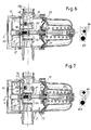
- Figs. 5 , 6 and 7 show the different positions of the stem 23 with the magnet 26 with respect to the second reed device 22, respectively corresponding to the cut-in pressures equal to 2.5 - 2 - 1.5 bar.
- the sensitivity of the second reed device 22 is indicated in the figures by an activation area S inside which the flow lines of the primary magnetic field M1 of the magnets must be contained. According to the value of the secondary magnetic field, this area S has larger or smaller dimensions.
- the lower cut-in pressure corresponds to the case in which the secondary magnetic field is substantially null, i.e. corresponds to the conventional case.
- the means 27 that generate the secondary magnetic field consist of at least one coil or inductance through which the electrical current circulates, thereby generating a magnetic field that surrounds the second reed device 22.
- the movement of the magnet is preferably orthogonal or almost orthogonal to the axes of the coils and to the card (and preferably orthogonal to the card).
- the electronic means for controlling and managing operation of the device preferably comprise a voltage stabilizer inside the circuit (not shown), a microcontroller processing circuit, with the program for managing the whole of the apparatus (not shown), a user interface (the control panel Q), a circuit for driving the pump (not shown), the first reed contact 20B for detecting the flow, the second reed contact 22 for detecting the pressure; a pair of coils (inductances) 28.
- the electronic control and management means also comprise means for varying the electrical current circulating along the coils 28, not described herein but of a type well known to the person skilled in the art.
- these variation means can be activated by pressing the button Q2 on the control panel Q.
- pressing the button Q2 this varies, through an appropriate drive circuit, the current circulating along the coils and therefore the total secondary magnetic field that surrounds the second reed device 22, varying the sensitivity thereof, as described above. Therefore, a given value of electrical current circulating along the coils (which can also be equal to "0") corresponds to each cut-in pressure.
- cut-in pressure the value of the hydraulic pressure for which the second reed 22 is activated is called cut-in pressure; the characteristic of the apparatus is that of providing a plurality of cut-in pressure values, which means that it can be regulated by the user.
- the cut-in pressure value depends firstly on the primary magnetic field generated by the magnet 26 (and therefore by its position with respect to the second reed device 22).
- the apparatus enables regulation of the cut-in pressure value by modifying the magnetic field that surrounds the reed 22 produced through the insertion of two coils (one or more) in position adjacent to the same reed device.
- the number of polarization levels corresponds to the number of cut-in pressures to be placed at the user's disposal.
- the values are pre-loaded in the memory of the electronic means, and determined during calibration of the apparatus.
Landscapes
- Engineering & Computer Science (AREA)
- Mechanical Engineering (AREA)
- General Engineering & Computer Science (AREA)
- Computer Hardware Design (AREA)
- Physics & Mathematics (AREA)
- Fluid Mechanics (AREA)
- Reciprocating Pumps (AREA)
- Control Of Non-Positive-Displacement Pumps (AREA)
- Control Of Positive-Displacement Pumps (AREA)
Claims (9)
- Appareil pour commander le démarrage et l'arrêt d'une pompe d'un réseau de distribution d'eau, comprenant :- une chambre (12) prévue avec une entrée (13) qui peut être associée fonctionnellement avec un côté de délivrance d'une pompe et une sortie (14) connectée de manière fonctionnelle au réseau hydrique,- un système (18) pour détecter et/ou mesurer le débit d'eau à travers ladite sortie (14) apte à émettre un signal de démarrage pour la pompe lorsqu'une valeur de seuil de débit prédéterminée est atteinte,- un dispositif (21) pour détecter et/ou mesurer la pression dans ladite chambre (12) apte à émettre un signal de démarrage pour la pompe du réseau lorsqu'une valeur prédéterminée définie comme étant une « redémarrage » est atteinte,- des moyens électroniques de commande et gestion (17) pour commander et gérer le fonctionnement du dispositif,- une pluralité de valeurs de pression de redémarrage prédéterminées stockées dans lesdits moyens électroniques de commande et de gestion (17) et des moyens d'interfaçage (Q) disponibles à l'utilisateur pour sélectionner l'une des valeurs de pression de redémarrage prédéterminées parmi ladite pluralité de valeurs de pression de redémarrage prédéterminées, caractérisé en ce que ledit dispositif pour détecter et/ou mesurer la pression (21) dans ladite chambre (12) comprend :- des moyens de détection (22), sensibles au champ magnétique, aptes à pour produire un effet/signal lorsque l'importance du champ magnétique qui entoure lesdits moyens de détection (22) excède une valeur de fonctionnement donnée, ledit effet/signal étant corrélé avec l'actionnement de ladite pompe,- un organe (23) sensible à la pression dans ladite chambre (12), déplaçable dans une direction en fonction de la valeur de la pression dans ladite chambre (12) de telle manière qu'une partie (23A) de cet organe se déplace vers ou s'éloigne desdits moyens de détection (22) sur la base de la pression dans ladite chambre (12),- des moyens magnétiques (26) intégrés à ladite partie (23A) de l'organe déplaçable, aptes à produire un champ magnétique défini comme étant un champ magnétique primaire (M1), la valeur du champ magnétique primaire (M1) qui entoure lesdits moyens de détection (22) étant corrélée à la valeur de la pression dans ladite chambre (12), la position dudit organe (23), ou la distance desdits moyens magnétiques (26) desdits moyens de détection (22) étant fonction de la pression dans ladite chambre (12).
- Appareil selon la revendication 1, dans lequel lesdits moyens de détection (22), sensibles au champ magnétique, comprennent un dispositif à lame.
- Appareil selon la revendication 1 ou 2, dans lequel lesdits moyens magnétiques comprennent au moins un aimant (26) intégré audit organe (23).
- Appareil selon une ou plusieurs des revendications 1, 2 ou 3, dans lequel ledit dispositif pour détecter et/ou mesurer la pression (21) dans ladite chambre (12) comprend des moyens (28) aptes à produire au moins un champ magnétique secondaire, distinct du champ magnétique primaire (M1) produit par lesdits moyens magnétiques (26), apte à entourer lesdits moyens de détection (22), ledit ou lesdits champ(s) magnétique(s) secondaire (s) entourant lesdits moyens de détection (22) avec une valeur telle qu'elle ne produit pas ledit effet/signal ; la valeur de fonctionnement qui produit ledit signal/effet étant donnée par la somme de la valeur du champ magnétique secondaire qui entoure lesdits moyens de détection (22) et de la valeur du champ magnétique primaire (M1) qui entoure les mêmes moyens de détection (22), une valeur corrélée dudit ou desdits champ(s) magnétique(s) secondaire(s) qui entoure lesdits moyens de détection (22) correspondant à chaque valeur de pression de redémarrage prédéterminée de ladite pluralité de valeurs sélectionnables par l'utilisateur.
- Appareil selon les revendications 2, 3 ou 4, dans lequel lesdits moyens pour produire ledit ou lesdits champ(s) magnétique(s) secondaire(s) comprennent au moins une bobine ou inductance (28) apte à générer un champ magnétique qui entoure ledit dispositif à lame.
- Appareil selon la revendication 5, dans lequel lesdits moyens de production dudit ou desdits champ(s) magnétique(s) secondaire(s) comprennent des moyens pour faire varier le courant circulant dans ladite bobine/inductance (28) associée avec lesdits moyens électroniques et avec lesdits moyens d'interfaçage (Q) sur lesquels il y a au moins une commande apte à faire varier la quantité dudit courant dans ladite ou lesdites bobine(s) (28).
- Appareil selon la revendication 5 ou 6, comprenant une carte électronique (17) dans laquelle est agencé ledit dispositif à lame et au moins une bobine (28) générant ledit ou lesdits champ(s) magnétique(s) secondaire(s) agencés du même côté de ladite carte (17) par rapport audit dispositif à lame.
- Appareil selon la revendication 5, 6 ou 7, comprenant au moins deux bobines (28) générant ledit ou lesdits champ(s) magnétique(s) secondaire(s) agencées avec leurs axes (x) de polarisation parallèles les uns aux autres ; l'axe de polarisation dudit ou desdits aimants (26) étant orthogonal au plan sur lequel les axes desdites bobines (28) s'étendent ; de préférence, la direction du mouvement dudit ou desdits aimant(s) (26) étant orthogonale au plan sur lequel les axes desdits bobines (28) s'étendent ; le plan sur lequel les axes desdits bobines (28) s'étendent étant de préférence sensiblement parallèles à ladite carte électronique (17).
- Appareil selon la revendication 8, dans lequel ledit dispositif à lame est compris dans un espace défini entre deux plans parallèles sur lesquels les axes desdites bobines (28) s'étendent.
Applications Claiming Priority (1)
| Application Number | Priority Date | Filing Date | Title |
|---|---|---|---|
| IT000079A ITFI20120079A1 (it) | 2012-04-20 | 2012-04-20 | "apparecchio per il controllo dell'avviamento e dell'arresto di una pompa di una rete di distribuzione idrica" |
Publications (2)
| Publication Number | Publication Date |
|---|---|
| EP2653725A1 EP2653725A1 (fr) | 2013-10-23 |
| EP2653725B1 true EP2653725B1 (fr) | 2017-05-17 |
Family
ID=46262148
Family Applications (1)
| Application Number | Title | Priority Date | Filing Date |
|---|---|---|---|
| EP13164394.2A Active EP2653725B1 (fr) | 2012-04-20 | 2013-04-19 | Appareil permettant de commander le démarrage et l'arrêt d'une pompe d'un réseau de distribution d'eau |
Country Status (3)
| Country | Link |
|---|---|
| EP (1) | EP2653725B1 (fr) |
| ES (1) | ES2637188T3 (fr) |
| IT (1) | ITFI20120079A1 (fr) |
Families Citing this family (4)
| Publication number | Priority date | Publication date | Assignee | Title |
|---|---|---|---|---|
| CN106401934A (zh) * | 2016-12-16 | 2017-02-15 | 浙江美泰泵业科技有限公司 | 水泵的智能控制结构 |
| ES2971291T3 (es) * | 2017-09-19 | 2024-06-04 | Trevitech S R L | Aparato de control de una bomba alimentada con corriente trifásica y método para controlar la fuente de alimentación de dicho aparato |
| CN108953126B (zh) * | 2018-09-04 | 2024-09-03 | 浙江耀达智能科技股份有限公司 | 一种免频繁启动、大功率电子开关 |
| ES1275679Y (es) * | 2021-03-29 | 2021-10-27 | Coelbo Control System S L | Dispositivo de control de encendido/ apagado de bomba hidráulica |
Family Cites Families (6)
| Publication number | Priority date | Publication date | Assignee | Title |
|---|---|---|---|---|
| IT1251968B (it) | 1991-10-21 | 1995-05-27 | Watertech Srl | Apparecchiatura per il controllo dell'avviamento e dell'arresto di unapompa di una rete di distribuzione di acqua. |
| DE19629136A1 (de) * | 1996-07-19 | 1998-01-22 | Gardena Kress & Kastner Gmbh | Steuereinrichtung für eine Förder-Pumpe o. dgl. |
| IT1295577B1 (it) * | 1997-02-13 | 1999-05-13 | Hydroservice S R L | Dispositivo per il comando di una pompa idraulica,a controllo proporzionale computerizzato autoregolante |
| ITMI20020275A1 (it) * | 2002-02-13 | 2003-08-13 | Schneider Electric Ind Italia | Dispositivo di comando per il funzionamento di una pompa autoclave diuna rete di distribuzione d'acqua |
| AU2002247957A1 (en) * | 2002-03-04 | 2003-09-16 | Watertech, S.P.A. | Apparatus for on/off controlling a pump in a liquid distribution network |
| US9360017B2 (en) * | 2009-01-23 | 2016-06-07 | Grundfos Pumps Corporation | Pump assembly having an integrated user interface |
-
2012
- 2012-04-20 IT IT000079A patent/ITFI20120079A1/it unknown
-
2013
- 2013-04-19 ES ES13164394.2T patent/ES2637188T3/es active Active
- 2013-04-19 EP EP13164394.2A patent/EP2653725B1/fr active Active
Also Published As
| Publication number | Publication date |
|---|---|
| ES2637188T3 (es) | 2017-10-11 |
| EP2653725A1 (fr) | 2013-10-23 |
| ITFI20120079A1 (it) | 2013-10-21 |
Similar Documents
| Publication | Publication Date | Title |
|---|---|---|
| EP2653725B1 (fr) | Appareil permettant de commander le démarrage et l'arrêt d'une pompe d'un réseau de distribution d'eau | |
| EP3282159B1 (fr) | Soupape de verrouillage | |
| KR101725621B1 (ko) | 물 배출 장치 및 그의 제어방법 | |
| US20090057583A1 (en) | Dual setpoint pressure controlled hydraulic valve | |
| US20100163768A1 (en) | Electromechanical Vlave | |
| EP2058442A2 (fr) | Appareil de contrôle de l'écoulement de l'eau | |
| EP3385971A1 (fr) | Pressostat électronique | |
| CN104095530A (zh) | 用电磁铁控制限压值的电压力锅 | |
| ES2653562T3 (es) | Aparato electrodoméstico con una electroválvula | |
| JP2016191501A (ja) | ドレンポンプ装置 | |
| KR102195871B1 (ko) | 고압 레귤레이터, 그의 압력 제어장치 및 제어방법 | |
| US20170184211A1 (en) | Electronic solenoid air vent | |
| CN203970088U (zh) | 用电磁铁控制限压值的电压力锅 | |
| JP2013101064A (ja) | 給水ユニットの制御装置 | |
| CN206451049U (zh) | 一种医用加速器水箱的自动补水装置 | |
| CN109965670A (zh) | 烹饪器具、烹饪器具的检测方法及检测系统 | |
| KR101856984B1 (ko) | 수위조절장치 및 이를 포함하는 수처리장치 | |
| KR101415969B1 (ko) | 보일러 온수용 가스제어 압전식 밸브 | |
| CN213757951U (zh) | 控制电路和料理机 | |
| EP2975485A1 (fr) | Ensemble de vannes adapté pour réaliser la connexion automatique d'un réseau d'alimentation en eau à un circuit primaire | |
| US20070023723A1 (en) | Electric valve for controlling the delivery of pressurized fluid | |
| CN105829785A (zh) | 具有电磁阀的家用器具 | |
| KR100913937B1 (ko) | 자석을 이용한 유량조절밸브 | |
| AU2009233609A1 (en) | Control assembly | |
| KR20110035157A (ko) | 전자식 급수밸브 |
Legal Events
| Date | Code | Title | Description |
|---|---|---|---|
| PUAI | Public reference made under article 153(3) epc to a published international application that has entered the european phase |
Free format text: ORIGINAL CODE: 0009012 |
|
| AK | Designated contracting states |
Kind code of ref document: A1 Designated state(s): AL AT BE BG CH CY CZ DE DK EE ES FI FR GB GR HR HU IE IS IT LI LT LU LV MC MK MT NL NO PL PT RO RS SE SI SK SM TR |
|
| AX | Request for extension of the european patent |
Extension state: BA ME |
|
| 17P | Request for examination filed |
Effective date: 20140418 |
|
| RBV | Designated contracting states (corrected) |
Designated state(s): AL AT BE BG CH CY CZ DE DK EE ES FI FR GB GR HR HU IE IS IT LI LT LU LV MC MK MT NL NO PL PT RO RS SE SI SK SM TR |
|
| GRAP | Despatch of communication of intention to grant a patent |
Free format text: ORIGINAL CODE: EPIDOSNIGR1 |
|
| INTG | Intention to grant announced |
Effective date: 20161207 |
|
| RAP1 | Party data changed (applicant data changed or rights of an application transferred) |
Owner name: TREVITECH S.R.L. |
|
| GRAS | Grant fee paid |
Free format text: ORIGINAL CODE: EPIDOSNIGR3 |
|
| GRAA | (expected) grant |
Free format text: ORIGINAL CODE: 0009210 |
|
| AK | Designated contracting states |
Kind code of ref document: B1 Designated state(s): AL AT BE BG CH CY CZ DE DK EE ES FI FR GB GR HR HU IE IS IT LI LT LU LV MC MK MT NL NO PL PT RO RS SE SI SK SM TR |
|
| REG | Reference to a national code |
Ref country code: GB Ref legal event code: FG4D |
|
| REG | Reference to a national code |
Ref country code: CH Ref legal event code: EP |
|
| REG | Reference to a national code |
Ref country code: IE Ref legal event code: FG4D |
|
| REG | Reference to a national code |
Ref country code: AT Ref legal event code: REF Ref document number: 894719 Country of ref document: AT Kind code of ref document: T Effective date: 20170615 |
|
| REG | Reference to a national code |
Ref country code: DE Ref legal event code: R096 Ref document number: 602013021163 Country of ref document: DE |
|
| REG | Reference to a national code |
Ref country code: NL Ref legal event code: MP Effective date: 20170517 |
|
| REG | Reference to a national code |
Ref country code: LT Ref legal event code: MG4D |
|
| REG | Reference to a national code |
Ref country code: ES Ref legal event code: FG2A Ref document number: 2637188 Country of ref document: ES Kind code of ref document: T3 Effective date: 20171011 |
|
| REG | Reference to a national code |
Ref country code: AT Ref legal event code: MK05 Ref document number: 894719 Country of ref document: AT Kind code of ref document: T Effective date: 20170517 |
|
| PG25 | Lapsed in a contracting state [announced via postgrant information from national office to epo] |
Ref country code: HR Free format text: LAPSE BECAUSE OF FAILURE TO SUBMIT A TRANSLATION OF THE DESCRIPTION OR TO PAY THE FEE WITHIN THE PRESCRIBED TIME-LIMIT Effective date: 20170517 Ref country code: FI Free format text: LAPSE BECAUSE OF FAILURE TO SUBMIT A TRANSLATION OF THE DESCRIPTION OR TO PAY THE FEE WITHIN THE PRESCRIBED TIME-LIMIT Effective date: 20170517 Ref country code: LT Free format text: LAPSE BECAUSE OF FAILURE TO SUBMIT A TRANSLATION OF THE DESCRIPTION OR TO PAY THE FEE WITHIN THE PRESCRIBED TIME-LIMIT Effective date: 20170517 Ref country code: AT Free format text: LAPSE BECAUSE OF FAILURE TO SUBMIT A TRANSLATION OF THE DESCRIPTION OR TO PAY THE FEE WITHIN THE PRESCRIBED TIME-LIMIT Effective date: 20170517 Ref country code: GR Free format text: LAPSE BECAUSE OF FAILURE TO SUBMIT A TRANSLATION OF THE DESCRIPTION OR TO PAY THE FEE WITHIN THE PRESCRIBED TIME-LIMIT Effective date: 20170818 Ref country code: NO Free format text: LAPSE BECAUSE OF FAILURE TO SUBMIT A TRANSLATION OF THE DESCRIPTION OR TO PAY THE FEE WITHIN THE PRESCRIBED TIME-LIMIT Effective date: 20170817 |
|
| PG25 | Lapsed in a contracting state [announced via postgrant information from national office to epo] |
Ref country code: PL Free format text: LAPSE BECAUSE OF FAILURE TO SUBMIT A TRANSLATION OF THE DESCRIPTION OR TO PAY THE FEE WITHIN THE PRESCRIBED TIME-LIMIT Effective date: 20170517 Ref country code: BG Free format text: LAPSE BECAUSE OF FAILURE TO SUBMIT A TRANSLATION OF THE DESCRIPTION OR TO PAY THE FEE WITHIN THE PRESCRIBED TIME-LIMIT Effective date: 20170817 Ref country code: RS Free format text: LAPSE BECAUSE OF FAILURE TO SUBMIT A TRANSLATION OF THE DESCRIPTION OR TO PAY THE FEE WITHIN THE PRESCRIBED TIME-LIMIT Effective date: 20170517 Ref country code: NL Free format text: LAPSE BECAUSE OF FAILURE TO SUBMIT A TRANSLATION OF THE DESCRIPTION OR TO PAY THE FEE WITHIN THE PRESCRIBED TIME-LIMIT Effective date: 20170517 Ref country code: LV Free format text: LAPSE BECAUSE OF FAILURE TO SUBMIT A TRANSLATION OF THE DESCRIPTION OR TO PAY THE FEE WITHIN THE PRESCRIBED TIME-LIMIT Effective date: 20170517 Ref country code: IS Free format text: LAPSE BECAUSE OF FAILURE TO SUBMIT A TRANSLATION OF THE DESCRIPTION OR TO PAY THE FEE WITHIN THE PRESCRIBED TIME-LIMIT Effective date: 20170917 Ref country code: SE Free format text: LAPSE BECAUSE OF FAILURE TO SUBMIT A TRANSLATION OF THE DESCRIPTION OR TO PAY THE FEE WITHIN THE PRESCRIBED TIME-LIMIT Effective date: 20170517 |
|
| PG25 | Lapsed in a contracting state [announced via postgrant information from national office to epo] |
Ref country code: CZ Free format text: LAPSE BECAUSE OF FAILURE TO SUBMIT A TRANSLATION OF THE DESCRIPTION OR TO PAY THE FEE WITHIN THE PRESCRIBED TIME-LIMIT Effective date: 20170517 Ref country code: EE Free format text: LAPSE BECAUSE OF FAILURE TO SUBMIT A TRANSLATION OF THE DESCRIPTION OR TO PAY THE FEE WITHIN THE PRESCRIBED TIME-LIMIT Effective date: 20170517 Ref country code: DK Free format text: LAPSE BECAUSE OF FAILURE TO SUBMIT A TRANSLATION OF THE DESCRIPTION OR TO PAY THE FEE WITHIN THE PRESCRIBED TIME-LIMIT Effective date: 20170517 Ref country code: SK Free format text: LAPSE BECAUSE OF FAILURE TO SUBMIT A TRANSLATION OF THE DESCRIPTION OR TO PAY THE FEE WITHIN THE PRESCRIBED TIME-LIMIT Effective date: 20170517 Ref country code: RO Free format text: LAPSE BECAUSE OF FAILURE TO SUBMIT A TRANSLATION OF THE DESCRIPTION OR TO PAY THE FEE WITHIN THE PRESCRIBED TIME-LIMIT Effective date: 20170517 |
|
| REG | Reference to a national code |
Ref country code: DE Ref legal event code: R097 Ref document number: 602013021163 Country of ref document: DE |
|
| PG25 | Lapsed in a contracting state [announced via postgrant information from national office to epo] |
Ref country code: SM Free format text: LAPSE BECAUSE OF FAILURE TO SUBMIT A TRANSLATION OF THE DESCRIPTION OR TO PAY THE FEE WITHIN THE PRESCRIBED TIME-LIMIT Effective date: 20170517 |
|
| PLBE | No opposition filed within time limit |
Free format text: ORIGINAL CODE: 0009261 |
|
| STAA | Information on the status of an ep patent application or granted ep patent |
Free format text: STATUS: NO OPPOSITION FILED WITHIN TIME LIMIT |
|
| 26N | No opposition filed |
Effective date: 20180220 |
|
| PG25 | Lapsed in a contracting state [announced via postgrant information from national office to epo] |
Ref country code: SI Free format text: LAPSE BECAUSE OF FAILURE TO SUBMIT A TRANSLATION OF THE DESCRIPTION OR TO PAY THE FEE WITHIN THE PRESCRIBED TIME-LIMIT Effective date: 20170517 |
|
| REG | Reference to a national code |
Ref country code: DE Ref legal event code: R119 Ref document number: 602013021163 Country of ref document: DE |
|
| PG25 | Lapsed in a contracting state [announced via postgrant information from national office to epo] |
Ref country code: MC Free format text: LAPSE BECAUSE OF FAILURE TO SUBMIT A TRANSLATION OF THE DESCRIPTION OR TO PAY THE FEE WITHIN THE PRESCRIBED TIME-LIMIT Effective date: 20170517 |
|
| REG | Reference to a national code |
Ref country code: CH Ref legal event code: PL |
|
| REG | Reference to a national code |
Ref country code: BE Ref legal event code: MM Effective date: 20180430 |
|
| GBPC | Gb: european patent ceased through non-payment of renewal fee |
Effective date: 20180419 |
|
| REG | Reference to a national code |
Ref country code: IE Ref legal event code: MM4A |
|
| PG25 | Lapsed in a contracting state [announced via postgrant information from national office to epo] |
Ref country code: DE Free format text: LAPSE BECAUSE OF NON-PAYMENT OF DUE FEES Effective date: 20181101 Ref country code: LU Free format text: LAPSE BECAUSE OF NON-PAYMENT OF DUE FEES Effective date: 20180419 |
|
| PG25 | Lapsed in a contracting state [announced via postgrant information from national office to epo] |
Ref country code: BE Free format text: LAPSE BECAUSE OF NON-PAYMENT OF DUE FEES Effective date: 20180430 Ref country code: GB Free format text: LAPSE BECAUSE OF NON-PAYMENT OF DUE FEES Effective date: 20180419 Ref country code: CH Free format text: LAPSE BECAUSE OF NON-PAYMENT OF DUE FEES Effective date: 20180430 Ref country code: LI Free format text: LAPSE BECAUSE OF NON-PAYMENT OF DUE FEES Effective date: 20180430 |
|
| PG25 | Lapsed in a contracting state [announced via postgrant information from national office to epo] |
Ref country code: FR Free format text: LAPSE BECAUSE OF NON-PAYMENT OF DUE FEES Effective date: 20180430 Ref country code: IE Free format text: LAPSE BECAUSE OF NON-PAYMENT OF DUE FEES Effective date: 20180419 |
|
| PG25 | Lapsed in a contracting state [announced via postgrant information from national office to epo] |
Ref country code: MT Free format text: LAPSE BECAUSE OF NON-PAYMENT OF DUE FEES Effective date: 20180419 |
|
| PG25 | Lapsed in a contracting state [announced via postgrant information from national office to epo] |
Ref country code: TR Free format text: LAPSE BECAUSE OF FAILURE TO SUBMIT A TRANSLATION OF THE DESCRIPTION OR TO PAY THE FEE WITHIN THE PRESCRIBED TIME-LIMIT Effective date: 20170517 |
|
| PG25 | Lapsed in a contracting state [announced via postgrant information from national office to epo] |
Ref country code: PT Free format text: LAPSE BECAUSE OF FAILURE TO SUBMIT A TRANSLATION OF THE DESCRIPTION OR TO PAY THE FEE WITHIN THE PRESCRIBED TIME-LIMIT Effective date: 20170517 Ref country code: HU Free format text: LAPSE BECAUSE OF FAILURE TO SUBMIT A TRANSLATION OF THE DESCRIPTION OR TO PAY THE FEE WITHIN THE PRESCRIBED TIME-LIMIT; INVALID AB INITIO Effective date: 20130419 |
|
| PG25 | Lapsed in a contracting state [announced via postgrant information from national office to epo] |
Ref country code: CY Free format text: LAPSE BECAUSE OF FAILURE TO SUBMIT A TRANSLATION OF THE DESCRIPTION OR TO PAY THE FEE WITHIN THE PRESCRIBED TIME-LIMIT Effective date: 20170517 Ref country code: MK Free format text: LAPSE BECAUSE OF NON-PAYMENT OF DUE FEES Effective date: 20170517 |
|
| PG25 | Lapsed in a contracting state [announced via postgrant information from national office to epo] |
Ref country code: AL Free format text: LAPSE BECAUSE OF FAILURE TO SUBMIT A TRANSLATION OF THE DESCRIPTION OR TO PAY THE FEE WITHIN THE PRESCRIBED TIME-LIMIT Effective date: 20170517 |
|
| PGFP | Annual fee paid to national office [announced via postgrant information from national office to epo] |
Ref country code: ES Payment date: 20250513 Year of fee payment: 13 |
|
| PGFP | Annual fee paid to national office [announced via postgrant information from national office to epo] |
Ref country code: IT Payment date: 20250422 Year of fee payment: 13 |