EP2653734A1 - Structure de joint de boulon - Google Patents
Structure de joint de boulon Download PDFInfo
- Publication number
- EP2653734A1 EP2653734A1 EP11848466.6A EP11848466A EP2653734A1 EP 2653734 A1 EP2653734 A1 EP 2653734A1 EP 11848466 A EP11848466 A EP 11848466A EP 2653734 A1 EP2653734 A1 EP 2653734A1
- Authority
- EP
- European Patent Office
- Prior art keywords
- joinable
- load
- bolts
- elastic modulus
- joint
- Prior art date
- Legal status (The legal status is an assumption and is not a legal conclusion. Google has not performed a legal analysis and makes no representation as to the accuracy of the status listed.)
- Granted
Links
Images

Classifications
-
- F—MECHANICAL ENGINEERING; LIGHTING; HEATING; WEAPONS; BLASTING
- F16—ENGINEERING ELEMENTS AND UNITS; GENERAL MEASURES FOR PRODUCING AND MAINTAINING EFFECTIVE FUNCTIONING OF MACHINES OR INSTALLATIONS; THERMAL INSULATION IN GENERAL
- F16B—DEVICES FOR FASTENING OR SECURING CONSTRUCTIONAL ELEMENTS OR MACHINE PARTS TOGETHER, e.g. NAILS, BOLTS, CIRCLIPS, CLAMPS, CLIPS OR WEDGES; JOINTS OR JOINTING
- F16B5/00—Joining sheets or plates, e.g. panels, to one another or to strips or bars parallel to them
- F16B5/02—Joining sheets or plates, e.g. panels, to one another or to strips or bars parallel to them by means of fastening members using screw-thread
-
- F—MECHANICAL ENGINEERING; LIGHTING; HEATING; WEAPONS; BLASTING
- F16—ENGINEERING ELEMENTS AND UNITS; GENERAL MEASURES FOR PRODUCING AND MAINTAINING EFFECTIVE FUNCTIONING OF MACHINES OR INSTALLATIONS; THERMAL INSULATION IN GENERAL
- F16B—DEVICES FOR FASTENING OR SECURING CONSTRUCTIONAL ELEMENTS OR MACHINE PARTS TOGETHER, e.g. NAILS, BOLTS, CIRCLIPS, CLAMPS, CLIPS OR WEDGES; JOINTS OR JOINTING
- F16B31/00—Screwed connections specially modified in view of tensile load; Break-bolts
- F16B31/06—Screwed connections specially modified in view of tensile load; Break-bolts having regard to possibility of fatigue rupture
-
- B—PERFORMING OPERATIONS; TRANSPORTING
- B64—AIRCRAFT; AVIATION; COSMONAUTICS
- B64C—AEROPLANES; HELICOPTERS
- B64C1/00—Fuselages; Constructional features common to fuselages, wings, stabilising surfaces or the like
- B64C1/06—Frames; Stringers; Longerons ; Fuselage sections
Definitions
- the present invention relates to a bolted joint structure suitable for use in a joint part which is strictly required to be lightweight and to have high joint strength, such as a joint part of a wing panel coupled to a body part of an airplane.
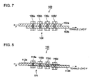
- FIG.7 A conventional bolted joint structure using a plurality of bolts is illustrated in FIG.7 .
- the bolt join structure 100 is configured such that a plurality of joint bolts 104a-104d (four bolts in FIG.7 ) for two plates 102a, 102 to be joined are arranged along a direction of tensile load F.
- bolts 104b, 104c disposed on a center side have less shared load than bolts 104a, 104d disposed on an outer end side due to small deflection difference of the plates which each transmit the load on the joint parts to the bolts. This state is indicated by line A in FIG.3 .
- the joint parts of the joinable member is made of a composite material
- the shared load between the bolts on the outer end side tend to be larger as the composite material has lower ductility than metal. Therefore, it is difficult to increase the load on the joint parts even by using more bolts to join the joint parts.
- the inventors have studied a variety of bolted joint structure for balancing the shared load on the bolts.
- the bolted joint structure invented by the inventors is illustrated in FIG.8 .
- the bolted joint structure 110 is configured so that the joinable plates 102a, 102b at the joint part each decrease in thickness toward its end.
- an elastic modulus of each plate 102a, 102b around each joining bolt decreases toward its end.
- stiffness of the plate can be reduced and thus the shared load is applied more evenly to the bolts than before.
- the bolted joint structure 110 has issues that, by reducing the thickness of the plates 102a, 102b at an outer part, the bolted joint structure 110 may not satisfy other design standards such as strength of the plate and also the shape of the joint part becomes more complicated, which results in more hours for machining the joint part.
- the joinable plate is made of a composite material which is formed by stacking a plurality of thin film sheets
- the number of stacked thin layer sheets must be reduced to change the thickness of the composite material. This may require more work and also strength symmetry or the like may be compromised by changing the thickness of the joint part.
- the inventors thought to reduce the width of the joinable plate 102a, 102b toward the end. As a result, the elastic modulus of the plate decreases toward the end and similarly the shared load among the bolts is balanced. However, this bolt joint structure may have an issue as far as satisfying the design standard such as the required strength or the like.
- a bolted joint structure according to the present invention comprises:
- elastic modulus of the joint parts or the load transfer member for transferring the load applied to the joint parts to the joining bolts is changed for each of the joining bolts. More specifically, a peripheral region of the joining bolt disposed on the outer end side is made of a material having a low elastic modulus to lower stiffness of the peripheral region. As a result, the shared load on the bolt on the outer end side is reduced. In this manner, the shared load is equalized among the joining bolts and thus the transferable load of the joint part increases in proportion to the number of the joining bolts. Further, the shared load of the joining bolts can be equalized regardless of configurations of the joint parts and thus, no extra work is needed to manufacture the joining parts.
- type and content of reinforcement fiber may vary in a base material of the joint part along the load direction so as to change the elastic modulus of the joint parts along the load direction.
- the load transfer member may be a reinforcing plate provided between the joint part of the joinable members and the joining bolts.
- the reinforcing plate whose elastic modulus varies along the load direction, no special process is needed for the joinable plate and joinable plate can be used regardless of its elastic modulus.
- the bolted joint structure can be made in a simple manner and at low cost.
- the load transfer member may be a sleeve, and the sleeve may be provided between the joint part of the joinable members and the joining bolts disposed on the outer end side of the joinable members and may have an elastic modulus lower than the joinable member.
- the sleeve of low elastic modulus only on the bolts disposed on the outer end side, it is possible to reduce the shared load on the bolts on the outer end side. Therefore, the joinable member may be used regardless of its elastic modulus and also the reinforcing plate is not needed. As a result, the bolted joint structure can be made in a simple manner and at low cost.
- the load transfer member may be a sleeve provided between the joint part of the joinable members and the joining bolts and the sleeve may have a lower elastic modulus on the outer end side of the joinable members.
- the bolted joint structure is configured with joinable members to be joined; and a plurality of joining bolts aligned along a load direction, the plurality of joining bolts joining the joinable members at joint parts, and the joint parts or a load transfer member for transferring the load applied to the joint parts to the joining bolts is made of a material having an elastic modulus lower at the joint part disposed on an outer end side of the joinable members so that shared load is applied evenly to each of the joining bolts.
- the shared load of the joining bolts can be equalized regardless of configurations of the joint parts. Therefore, no extra work is needed for the joining parts and it is possible to attain the bolted joint structure that does not conflict with the design standards.
- FIG.1 is a schematic illustration of a bolted joint structure 10 according to this embodiment.
- plate members 12a, 12b to be joined to each other are made of a composite material.
- Joint parts 14 of the plate members 12a, 12b each have four sections T 1 to T 4 that vary in elastic modulus from an inner side toward an outer end side of each joinable plate member.
- the elastic modulus (E 1 to E 4 ) of these sections have the following relationship. E 1 T 1 > E 2 T 2 > E 3 T 3 > E 4 T 4
- FIG.2 configurations of the joint parts 14 of the joinable plate members 12a, 12b are described below using the plate member 12a as an example.
- two types of fiber C and G are reinforcing agents of the composite material making the plate member 12a. Thick lines are the fiber C whereas thin lines are the fiber G.
- the fiber C and the fiber G has a relationship of elastic modulus, Fiber C > Fiber G.
- the fiber C is carbon fiber and the fiber G is glass fiber.
- the joinable plate member 12b is produced in the same manner as the joinable plate member 12a.
- the joinable plate member 12a, 12b may be produced by separately forming a plurality of thin-film sheets formed of fibers and matrix and then stacking the thin-film sheets together.
- the joinable plate member 12a, 12b may be produced as a plate member having a thickness of the joinable plate member without the stacking step.
- the joint parts of the joinable plate members 12a, 12b produced in this manner are joined together by arranging joining bolts 16a to 16d in the sections T 1 to T 4 respectively.
- the joint parts 14 are subjected to the tensile load F.
- the joinable plate members 12a, 12b decrease in elastic modulus toward the end and thus the joinable plate members 12a, 12b decrease in stiffness toward the end. Therefore, it is possible to reduce the shared load on the joining bolt disposed on the end side. More specifically, the load on each bolt changes as indicated by line B of FIG.3 .
- this bolted joint structure is applicable to joint parts where strict joint strength is required such as joint parts of a blade or a fuselage of an aircraft.
- this bolted joint structure is applicable to joint parts where strict joint strength is required such as joint parts of a blade or a fuselage of an aircraft.
- the thickness of the joinable plate members 12a, 12b is not changed and thus, the use of the composite material does not require additional processing.
- the joinable plate members 12a, 12b are made of a composite material, types and percentages of the fibers in the form of reinforcing agents may be changed. This makes it easier to change the elastic moduli of the sections along the load direction.
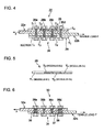
- a second embodiment of the present invention is described in reference to FIG.4 and FIG.5 .
- a bolted joint structure of this embodiment includes a reinforcing plate 28 at the joint parts 24.
- the joinable plate members 22a, 22b are made of a composite material. However, this composite material is not formed in such a manner that the elastic modulus varies in the load direction as in the case of the first embodiment.
- a pair of the reinforcing plates 28 is provided between the joinable plate member 22a and the joining bolts 26a to 26d, and between the joinable plate member 22a, 22b and each bolt.
- the reinforcing plate 28a is described in reference to FIG.5 .
- the reinforcing member is made of a composite material which is produced in the same manner as the joinable plates 12a, 12b of the first embodiment shown in FIG.2 .
- the reinforcing plate 28 has four sections T 1 to T 4 that vary in elastic modulus formed by changing types and percentages of the fibers in the form of reinforcing agents in the direction the tensile load F is applied.
- the elastic modulus (E 1 to E 4 ) of these sections have the following relationship. E 1 T 1 > E 2 T 2 > E 3 T 3 > E 4 T 4
- This pair of reinforcing plates 28 having the above configuration is arranged so that the section T 4 having low elastic modulus is positioned on the outer end side of the joint parts of the joinable plates 22a, 22b and the section T 1 having high elastic modulus is positioned on the center side.
- the tensile load F is transmitted from the joinable plates 22a, 22b via the reinforcing plates 28.
- the load is transmitted from the reinforcing plate 28 of low elastic modulus and low stiffness, thereby reducing the shared load. More specifically, the load applied on each of the joining bolts 26a-26d of this embodiment is indicated by line B in FIG.3 .
- a third embodiment of the present invention is described in reference to FIG.6 .
- a bolted joint structure 30 of this embodiment is configured such that four joining bolts 36a-36d are provided at a joint part 34b and a sleeve 38 is provided between a screw part 37 of each of the joining bolts 36a, 36d disposed on the outer end side and each of the joinable plates 32a, 32b.
- the joinable plates 32a, 32b of this embodiment uses a composite material whose elastic modulus is not varied, in the same manner as the second embodiment.
- the sleeve 38 is made of a material having lower elastic modulus than the joinable plates 32a, 32b.
- the tensile load F is transmitted via the sleeves 38.
- the shared load on the bolts 36a, 36d on the outer end side decreases as indicated by line B in FIG.3 , thereby applying the shared load evenly on each of the joining bolts 36a-36d.
- the joinable plates 32a, 32b may be made of a regular composite material. Further, it is not necessary to use the reinforcing plate 28 whose elastic modulus varies as in the case of the second embodiment.
- the sleeves 38 By simply providing at the bolts 36a, 36d the sleeves 38 having lower modulus than the joinable plates 32a, 32b, it is easy to process compared to the first and second embodiments.
- the sleeves 38 are provided at the bolts 36a, 36d disposed on the outer end side.
- the sleeves may be provided at the bolts 36b, 36c disposed on the center side in addition to the bolts 36a, 36d and the sleeves at the bolts 36b, 36c on the center side may have higher elastic modulus than the sleeves 38 at the bolts 36a, 36d on the outer end side.
- the shared load can be applied to each of the joining bolts evenly in this manner as well.
- the shared load is equalized among the joining bolts in a simple manner and at low cost and joint strength can be increased in proportion to the number of the joining bolts and the bolted joint structure is suitable for use in a joint part which requires lightweight and high joint strength, such as a joint part of a wing panel coupled to a body part of an airplane.
Landscapes
- Engineering & Computer Science (AREA)
- General Engineering & Computer Science (AREA)
- Mechanical Engineering (AREA)
- Connection Of Plates (AREA)
Applications Claiming Priority (2)
| Application Number | Priority Date | Filing Date | Title |
|---|---|---|---|
| JP2010277755A JP5693195B2 (ja) | 2010-12-14 | 2010-12-14 | ボルト継手構造 |
| PCT/JP2011/073411 WO2012081298A1 (fr) | 2010-12-14 | 2011-10-12 | Structure de joint de boulon |
Publications (3)
| Publication Number | Publication Date |
|---|---|
| EP2653734A1 true EP2653734A1 (fr) | 2013-10-23 |
| EP2653734A4 EP2653734A4 (fr) | 2016-01-06 |
| EP2653734B1 EP2653734B1 (fr) | 2018-04-18 |
Family
ID=46244413
Family Applications (1)
| Application Number | Title | Priority Date | Filing Date |
|---|---|---|---|
| EP11848466.6A Not-in-force EP2653734B1 (fr) | 2010-12-14 | 2011-10-12 | Structure de joint de boulon |
Country Status (7)
| Country | Link |
|---|---|
| US (1) | US9157462B2 (fr) |
| EP (1) | EP2653734B1 (fr) |
| JP (1) | JP5693195B2 (fr) |
| CN (1) | CN103154534B (fr) |
| BR (1) | BR112013010753B1 (fr) |
| CA (1) | CA2813166C (fr) |
| WO (1) | WO2012081298A1 (fr) |
Families Citing this family (2)
| Publication number | Priority date | Publication date | Assignee | Title |
|---|---|---|---|---|
| JP6460461B2 (ja) * | 2014-12-26 | 2019-01-30 | いすゞ自動車株式会社 | 車輪速センサの取付構造 |
| JP6985192B2 (ja) * | 2018-03-19 | 2021-12-22 | 三菱重工業株式会社 | 複合材組立体 |
Family Cites Families (15)
| Publication number | Priority date | Publication date | Assignee | Title |
|---|---|---|---|---|
| US3270410A (en) * | 1963-05-20 | 1966-09-06 | Briles Mfg | Method of prestressed fastening of materials |
| DE2736124C3 (de) * | 1977-08-11 | 1981-11-12 | Messerschmitt-Bölkow-Blohm GmbH, 8000 München | Verfahren und Wickelwerkzeug zum Herstellen eines an den Enden offenen schlaufenförmigen Kraftübertragungselements aus Faserverbundwerkstoff |
| US4579475A (en) * | 1984-01-23 | 1986-04-01 | The United States Of America As Represented By The Administrator Of The National Aeronautics And Space Administration | Optimized bolted joint |
| SU1224476A1 (ru) * | 1984-11-22 | 1986-04-15 | Московский авиационный технологический институт им.К.Э.Циолковского | Соединение деталей (его варианты) |
| JPH07156888A (ja) * | 1993-12-09 | 1995-06-20 | Mitsubishi Heavy Ind Ltd | 複合材フィッティング |
| US5720134A (en) * | 1997-01-02 | 1998-02-24 | Kurtz; William | Post having plastic base |
| JP2000141064A (ja) * | 1998-11-11 | 2000-05-23 | Nippon Steel Corp | 異強度材の高力ボルト摩擦接合用スプライスプレート |
| DE19925953C1 (de) * | 1999-06-08 | 2000-09-07 | Deutsch Zentr Luft & Raumfahrt | Bolzenverbindung für Faserverbundstrukturen |
| JP4238311B2 (ja) * | 2002-12-19 | 2009-03-18 | 防衛省技術研究本部長 | 3次元複合材継ぎ手 |
| DE102004045845B3 (de) * | 2004-09-20 | 2005-12-15 | Deutsches Zentrum für Luft- und Raumfahrt e.V. | Faserverbundstruktur mit einer Bolzenverbindung und Herstellungsverfahren dafür |
| EP1861227B1 (fr) * | 2005-03-23 | 2012-10-24 | Bell Helicopter Textron Inc. | Dispositif pour assembler des elements et ensemble constitue de ce dispositif et de ces elements |
| FR2883548B1 (fr) * | 2005-03-23 | 2007-06-15 | Airbus France Sas | Dispositif et procede d'eclissage mixte carbone-metal dissymetrique |
| US7837148B2 (en) * | 2006-06-13 | 2010-11-23 | The Boeing Company | Composite wing-body joint |
| GB0708333D0 (en) * | 2007-04-30 | 2007-06-06 | Airbus Uk Ltd | Composite structure |
| US8393068B2 (en) | 2007-11-06 | 2013-03-12 | The Boeing Company | Method and apparatus for assembling composite structures |
-
2010
- 2010-12-14 JP JP2010277755A patent/JP5693195B2/ja active Active
-
2011
- 2011-10-12 WO PCT/JP2011/073411 patent/WO2012081298A1/fr not_active Ceased
- 2011-10-12 CN CN201180049336.1A patent/CN103154534B/zh not_active Expired - Fee Related
- 2011-10-12 CA CA2813166A patent/CA2813166C/fr not_active Expired - Fee Related
- 2011-10-12 BR BR112013010753A patent/BR112013010753B1/pt not_active IP Right Cessation
- 2011-10-12 US US13/879,886 patent/US9157462B2/en active Active
- 2011-10-12 EP EP11848466.6A patent/EP2653734B1/fr not_active Not-in-force
Also Published As
| Publication number | Publication date |
|---|---|
| JP2012127387A (ja) | 2012-07-05 |
| CN103154534B (zh) | 2015-08-19 |
| CA2813166A1 (fr) | 2012-06-21 |
| US20130287490A1 (en) | 2013-10-31 |
| US9157462B2 (en) | 2015-10-13 |
| EP2653734A4 (fr) | 2016-01-06 |
| CN103154534A (zh) | 2013-06-12 |
| JP5693195B2 (ja) | 2015-04-01 |
| BR112013010753A2 (pt) | 2016-08-09 |
| WO2012081298A1 (fr) | 2012-06-21 |
| BR112013010753B1 (pt) | 2020-06-09 |
| EP2653734B1 (fr) | 2018-04-18 |
| CA2813166C (fr) | 2015-12-22 |
Similar Documents
| Publication | Publication Date | Title |
|---|---|---|
| EP2406071B1 (fr) | Structures composites employant des stratifiés quasi-isotropes | |
| US7857258B2 (en) | Assembly of panels of an airplane fuselage | |
| EP2484496A1 (fr) | Robot | |
| EP2305559B1 (fr) | Agencement d'un joint circonférentiel d'éléments structuraux avec un élément de couplage fabriqué en matériau composite | |
| CA2797195A1 (fr) | Membrure de poutre composite entre plaques de renforcement et procede de fabrication associe | |
| JP5654055B2 (ja) | 複合材構造体、これを備えた航空機主翼および航空機胴体 | |
| US20140377500A1 (en) | Composite structure, aircraft wing and aircraft fuselage including composite structure, and method of manufacturing composite structure | |
| JP2014237437A (ja) | 航空機翼アセンブリの外弦翼ボックスと中央翼セクションとの下側結合部 | |
| US10259557B2 (en) | Pressure bulkhead for an aircraft fuselage, and an aircraft comprising such a pressure bulkhead | |
| EP2532581B1 (fr) | Jonction de profil en T de matériaux composites | |
| US7851040B2 (en) | Methods for making composite material components especially useful for aircraft, and composite material components thereof | |
| CN101242992B (zh) | 用于机翼的支撑结构 | |
| EP2653734A1 (fr) | Structure de joint de boulon | |
| US8356771B2 (en) | Coupling for joining two frame segments | |
| US20100243804A1 (en) | Joint arrangement for composite-material structural members | |
| US9939026B2 (en) | Universal joints | |
| EP3770447A1 (fr) | Assemblage de matériau composite | |
| WO2017204451A1 (fr) | Panneau composite à fibres de renforcement ayant un raccord inséré horizontalement | |
| EP3769944A1 (fr) | Arbre d'entraînement composite selon un couple unidirectionnel dominant |
Legal Events
| Date | Code | Title | Description |
|---|---|---|---|
| PUAI | Public reference made under article 153(3) epc to a published international application that has entered the european phase |
Free format text: ORIGINAL CODE: 0009012 |
|
| 17P | Request for examination filed |
Effective date: 20130320 |
|
| AK | Designated contracting states |
Kind code of ref document: A1 Designated state(s): AL AT BE BG CH CY CZ DE DK EE ES FI FR GB GR HR HU IE IS IT LI LT LU LV MC MK MT NL NO PL PT RO RS SE SI SK SM TR |
|
| DAX | Request for extension of the european patent (deleted) | ||
| RA4 | Supplementary search report drawn up and despatched (corrected) |
Effective date: 20151204 |
|
| RIC1 | Information provided on ipc code assigned before grant |
Ipc: B64C 1/00 20060101ALI20151130BHEP Ipc: F16B 5/02 20060101AFI20151130BHEP Ipc: B64C 1/06 20060101ALN20151130BHEP Ipc: F16B 31/06 20060101ALI20151130BHEP |
|
| GRAP | Despatch of communication of intention to grant a patent |
Free format text: ORIGINAL CODE: EPIDOSNIGR1 |
|
| INTG | Intention to grant announced |
Effective date: 20171204 |
|
| GRAS | Grant fee paid |
Free format text: ORIGINAL CODE: EPIDOSNIGR3 |
|
| GRAA | (expected) grant |
Free format text: ORIGINAL CODE: 0009210 |
|
| AK | Designated contracting states |
Kind code of ref document: B1 Designated state(s): AL AT BE BG CH CY CZ DE DK EE ES FI FR GB GR HR HU IE IS IT LI LT LU LV MC MK MT NL NO PL PT RO RS SE SI SK SM TR |
|
| REG | Reference to a national code |
Ref country code: GB Ref legal event code: FG4D |
|
| REG | Reference to a national code |
Ref country code: CH Ref legal event code: EP |
|
| REG | Reference to a national code |
Ref country code: AT Ref legal event code: REF Ref document number: 990811 Country of ref document: AT Kind code of ref document: T Effective date: 20180515 |
|
| REG | Reference to a national code |
Ref country code: IE Ref legal event code: FG4D |
|
| REG | Reference to a national code |
Ref country code: DE Ref legal event code: R096 Ref document number: 602011047677 Country of ref document: DE |
|
| REG | Reference to a national code |
Ref country code: NL Ref legal event code: MP Effective date: 20180418 |
|
| REG | Reference to a national code |
Ref country code: LT Ref legal event code: MG4D |
|
| PG25 | Lapsed in a contracting state [announced via postgrant information from national office to epo] |
Ref country code: NL Free format text: LAPSE BECAUSE OF FAILURE TO SUBMIT A TRANSLATION OF THE DESCRIPTION OR TO PAY THE FEE WITHIN THE PRESCRIBED TIME-LIMIT Effective date: 20180418 |
|
| REG | Reference to a national code |
Ref country code: FR Ref legal event code: PLFP Year of fee payment: 8 |
|
| PG25 | Lapsed in a contracting state [announced via postgrant information from national office to epo] |
Ref country code: LT Free format text: LAPSE BECAUSE OF FAILURE TO SUBMIT A TRANSLATION OF THE DESCRIPTION OR TO PAY THE FEE WITHIN THE PRESCRIBED TIME-LIMIT Effective date: 20180418 Ref country code: FI Free format text: LAPSE BECAUSE OF FAILURE TO SUBMIT A TRANSLATION OF THE DESCRIPTION OR TO PAY THE FEE WITHIN THE PRESCRIBED TIME-LIMIT Effective date: 20180418 Ref country code: NO Free format text: LAPSE BECAUSE OF FAILURE TO SUBMIT A TRANSLATION OF THE DESCRIPTION OR TO PAY THE FEE WITHIN THE PRESCRIBED TIME-LIMIT Effective date: 20180718 Ref country code: SE Free format text: LAPSE BECAUSE OF FAILURE TO SUBMIT A TRANSLATION OF THE DESCRIPTION OR TO PAY THE FEE WITHIN THE PRESCRIBED TIME-LIMIT Effective date: 20180418 Ref country code: ES Free format text: LAPSE BECAUSE OF FAILURE TO SUBMIT A TRANSLATION OF THE DESCRIPTION OR TO PAY THE FEE WITHIN THE PRESCRIBED TIME-LIMIT Effective date: 20180418 Ref country code: PL Free format text: LAPSE BECAUSE OF FAILURE TO SUBMIT A TRANSLATION OF THE DESCRIPTION OR TO PAY THE FEE WITHIN THE PRESCRIBED TIME-LIMIT Effective date: 20180418 Ref country code: AL Free format text: LAPSE BECAUSE OF FAILURE TO SUBMIT A TRANSLATION OF THE DESCRIPTION OR TO PAY THE FEE WITHIN THE PRESCRIBED TIME-LIMIT Effective date: 20180418 Ref country code: BG Free format text: LAPSE BECAUSE OF FAILURE TO SUBMIT A TRANSLATION OF THE DESCRIPTION OR TO PAY THE FEE WITHIN THE PRESCRIBED TIME-LIMIT Effective date: 20180718 |
|
| PG25 | Lapsed in a contracting state [announced via postgrant information from national office to epo] |
Ref country code: LV Free format text: LAPSE BECAUSE OF FAILURE TO SUBMIT A TRANSLATION OF THE DESCRIPTION OR TO PAY THE FEE WITHIN THE PRESCRIBED TIME-LIMIT Effective date: 20180418 Ref country code: RS Free format text: LAPSE BECAUSE OF FAILURE TO SUBMIT A TRANSLATION OF THE DESCRIPTION OR TO PAY THE FEE WITHIN THE PRESCRIBED TIME-LIMIT Effective date: 20180418 Ref country code: GR Free format text: LAPSE BECAUSE OF FAILURE TO SUBMIT A TRANSLATION OF THE DESCRIPTION OR TO PAY THE FEE WITHIN THE PRESCRIBED TIME-LIMIT Effective date: 20180719 Ref country code: HR Free format text: LAPSE BECAUSE OF FAILURE TO SUBMIT A TRANSLATION OF THE DESCRIPTION OR TO PAY THE FEE WITHIN THE PRESCRIBED TIME-LIMIT Effective date: 20180418 |
|
| REG | Reference to a national code |
Ref country code: AT Ref legal event code: MK05 Ref document number: 990811 Country of ref document: AT Kind code of ref document: T Effective date: 20180418 |
|
| PG25 | Lapsed in a contracting state [announced via postgrant information from national office to epo] |
Ref country code: PT Free format text: LAPSE BECAUSE OF FAILURE TO SUBMIT A TRANSLATION OF THE DESCRIPTION OR TO PAY THE FEE WITHIN THE PRESCRIBED TIME-LIMIT Effective date: 20180820 |
|
| REG | Reference to a national code |
Ref country code: DE Ref legal event code: R097 Ref document number: 602011047677 Country of ref document: DE |
|
| PG25 | Lapsed in a contracting state [announced via postgrant information from national office to epo] |
Ref country code: AT Free format text: LAPSE BECAUSE OF FAILURE TO SUBMIT A TRANSLATION OF THE DESCRIPTION OR TO PAY THE FEE WITHIN THE PRESCRIBED TIME-LIMIT Effective date: 20180418 Ref country code: DK Free format text: LAPSE BECAUSE OF FAILURE TO SUBMIT A TRANSLATION OF THE DESCRIPTION OR TO PAY THE FEE WITHIN THE PRESCRIBED TIME-LIMIT Effective date: 20180418 Ref country code: EE Free format text: LAPSE BECAUSE OF FAILURE TO SUBMIT A TRANSLATION OF THE DESCRIPTION OR TO PAY THE FEE WITHIN THE PRESCRIBED TIME-LIMIT Effective date: 20180418 Ref country code: SK Free format text: LAPSE BECAUSE OF FAILURE TO SUBMIT A TRANSLATION OF THE DESCRIPTION OR TO PAY THE FEE WITHIN THE PRESCRIBED TIME-LIMIT Effective date: 20180418 Ref country code: RO Free format text: LAPSE BECAUSE OF FAILURE TO SUBMIT A TRANSLATION OF THE DESCRIPTION OR TO PAY THE FEE WITHIN THE PRESCRIBED TIME-LIMIT Effective date: 20180418 Ref country code: CZ Free format text: LAPSE BECAUSE OF FAILURE TO SUBMIT A TRANSLATION OF THE DESCRIPTION OR TO PAY THE FEE WITHIN THE PRESCRIBED TIME-LIMIT Effective date: 20180418 |
|
| PLBE | No opposition filed within time limit |
Free format text: ORIGINAL CODE: 0009261 |
|
| STAA | Information on the status of an ep patent application or granted ep patent |
Free format text: STATUS: NO OPPOSITION FILED WITHIN TIME LIMIT |
|
| PG25 | Lapsed in a contracting state [announced via postgrant information from national office to epo] |
Ref country code: IT Free format text: LAPSE BECAUSE OF FAILURE TO SUBMIT A TRANSLATION OF THE DESCRIPTION OR TO PAY THE FEE WITHIN THE PRESCRIBED TIME-LIMIT Effective date: 20180418 Ref country code: SM Free format text: LAPSE BECAUSE OF FAILURE TO SUBMIT A TRANSLATION OF THE DESCRIPTION OR TO PAY THE FEE WITHIN THE PRESCRIBED TIME-LIMIT Effective date: 20180418 |
|
| 26N | No opposition filed |
Effective date: 20190121 |
|
| PG25 | Lapsed in a contracting state [announced via postgrant information from national office to epo] |
Ref country code: SI Free format text: LAPSE BECAUSE OF FAILURE TO SUBMIT A TRANSLATION OF THE DESCRIPTION OR TO PAY THE FEE WITHIN THE PRESCRIBED TIME-LIMIT Effective date: 20180418 |
|
| REG | Reference to a national code |
Ref country code: CH Ref legal event code: PL |
|
| GBPC | Gb: european patent ceased through non-payment of renewal fee |
Effective date: 20181012 |
|
| REG | Reference to a national code |
Ref country code: BE Ref legal event code: MM Effective date: 20181031 |
|
| PG25 | Lapsed in a contracting state [announced via postgrant information from national office to epo] |
Ref country code: LU Free format text: LAPSE BECAUSE OF NON-PAYMENT OF DUE FEES Effective date: 20181012 Ref country code: MC Free format text: LAPSE BECAUSE OF FAILURE TO SUBMIT A TRANSLATION OF THE DESCRIPTION OR TO PAY THE FEE WITHIN THE PRESCRIBED TIME-LIMIT Effective date: 20180418 |
|
| REG | Reference to a national code |
Ref country code: IE Ref legal event code: MM4A |
|
| PG25 | Lapsed in a contracting state [announced via postgrant information from national office to epo] |
Ref country code: BE Free format text: LAPSE BECAUSE OF NON-PAYMENT OF DUE FEES Effective date: 20181031 Ref country code: CH Free format text: LAPSE BECAUSE OF NON-PAYMENT OF DUE FEES Effective date: 20181031 Ref country code: LI Free format text: LAPSE BECAUSE OF NON-PAYMENT OF DUE FEES Effective date: 20181031 |
|
| PG25 | Lapsed in a contracting state [announced via postgrant information from national office to epo] |
Ref country code: IE Free format text: LAPSE BECAUSE OF NON-PAYMENT OF DUE FEES Effective date: 20181012 Ref country code: GB Free format text: LAPSE BECAUSE OF NON-PAYMENT OF DUE FEES Effective date: 20181012 |
|
| PG25 | Lapsed in a contracting state [announced via postgrant information from national office to epo] |
Ref country code: MT Free format text: LAPSE BECAUSE OF NON-PAYMENT OF DUE FEES Effective date: 20181012 |
|
| PG25 | Lapsed in a contracting state [announced via postgrant information from national office to epo] |
Ref country code: TR Free format text: LAPSE BECAUSE OF FAILURE TO SUBMIT A TRANSLATION OF THE DESCRIPTION OR TO PAY THE FEE WITHIN THE PRESCRIBED TIME-LIMIT Effective date: 20180418 |
|
| PG25 | Lapsed in a contracting state [announced via postgrant information from national office to epo] |
Ref country code: HU Free format text: LAPSE BECAUSE OF FAILURE TO SUBMIT A TRANSLATION OF THE DESCRIPTION OR TO PAY THE FEE WITHIN THE PRESCRIBED TIME-LIMIT; INVALID AB INITIO Effective date: 20111012 Ref country code: CY Free format text: LAPSE BECAUSE OF FAILURE TO SUBMIT A TRANSLATION OF THE DESCRIPTION OR TO PAY THE FEE WITHIN THE PRESCRIBED TIME-LIMIT Effective date: 20180418 Ref country code: MK Free format text: LAPSE BECAUSE OF NON-PAYMENT OF DUE FEES Effective date: 20180418 |
|
| PG25 | Lapsed in a contracting state [announced via postgrant information from national office to epo] |
Ref country code: IS Free format text: LAPSE BECAUSE OF FAILURE TO SUBMIT A TRANSLATION OF THE DESCRIPTION OR TO PAY THE FEE WITHIN THE PRESCRIBED TIME-LIMIT Effective date: 20180818 |
|
| PGFP | Annual fee paid to national office [announced via postgrant information from national office to epo] |
Ref country code: FR Payment date: 20200914 Year of fee payment: 10 |
|
| PGFP | Annual fee paid to national office [announced via postgrant information from national office to epo] |
Ref country code: DE Payment date: 20200929 Year of fee payment: 10 |
|
| REG | Reference to a national code |
Ref country code: DE Ref legal event code: R119 Ref document number: 602011047677 Country of ref document: DE |
|
| PG25 | Lapsed in a contracting state [announced via postgrant information from national office to epo] |
Ref country code: DE Free format text: LAPSE BECAUSE OF NON-PAYMENT OF DUE FEES Effective date: 20220503 |
|
| PG25 | Lapsed in a contracting state [announced via postgrant information from national office to epo] |
Ref country code: FR Free format text: LAPSE BECAUSE OF NON-PAYMENT OF DUE FEES Effective date: 20211031 |