EP2653737A2 - Bearing race with defined contact areas - Google Patents
Bearing race with defined contact areas Download PDFInfo
- Publication number
- EP2653737A2 EP2653737A2 EP13164335.5A EP13164335A EP2653737A2 EP 2653737 A2 EP2653737 A2 EP 2653737A2 EP 13164335 A EP13164335 A EP 13164335A EP 2653737 A2 EP2653737 A2 EP 2653737A2
- Authority
- EP
- European Patent Office
- Prior art keywords
- raceway
- ball
- housing bore
- cage
- bearing housing
- Prior art date
- Legal status (The legal status is an assumption and is not a legal conclusion. Google has not performed a legal analysis and makes no representation as to the accuracy of the status listed.)
- Granted
Links
Images

Classifications
-
- F—MECHANICAL ENGINEERING; LIGHTING; HEATING; WEAPONS; BLASTING
- F16—ENGINEERING ELEMENTS AND UNITS; GENERAL MEASURES FOR PRODUCING AND MAINTAINING EFFECTIVE FUNCTIONING OF MACHINES OR INSTALLATIONS; THERMAL INSULATION IN GENERAL
- F16C—SHAFTS; FLEXIBLE SHAFTS; ELEMENTS OR CRANKSHAFT MECHANISMS; ROTARY BODIES OTHER THAN GEARING ELEMENTS; BEARINGS
- F16C29/00—Bearings for parts moving only linearly
- F16C29/04—Ball or roller bearings
- F16C29/06—Ball or roller bearings in which the rolling bodies circulate partly without carrying load
- F16C29/0602—Details of the bearing body or carriage or parts thereof, e.g. methods for manufacturing or assembly
- F16C29/0604—Details of the bearing body or carriage or parts thereof, e.g. methods for manufacturing or assembly of the load bearing section
-
- F—MECHANICAL ENGINEERING; LIGHTING; HEATING; WEAPONS; BLASTING
- F16—ENGINEERING ELEMENTS AND UNITS; GENERAL MEASURES FOR PRODUCING AND MAINTAINING EFFECTIVE FUNCTIONING OF MACHINES OR INSTALLATIONS; THERMAL INSULATION IN GENERAL
- F16C—SHAFTS; FLEXIBLE SHAFTS; ELEMENTS OR CRANKSHAFT MECHANISMS; ROTARY BODIES OTHER THAN GEARING ELEMENTS; BEARINGS
- F16C29/00—Bearings for parts moving only linearly
- F16C29/04—Ball or roller bearings
- F16C29/06—Ball or roller bearings in which the rolling bodies circulate partly without carrying load
- F16C29/068—Ball or roller bearings in which the rolling bodies circulate partly without carrying load with the bearing body fully encircling the guide rail or track
- F16C29/0683—Ball or roller bearings in which the rolling bodies circulate partly without carrying load with the bearing body fully encircling the guide rail or track the bearing body encircles a rail or rod of circular cross-section, i.e. the linear bearing is not suited to transmit torque
- F16C29/0685—Ball or roller bearings in which the rolling bodies circulate partly without carrying load with the bearing body fully encircling the guide rail or track the bearing body encircles a rail or rod of circular cross-section, i.e. the linear bearing is not suited to transmit torque with balls
- F16C29/069—Ball or roller bearings in which the rolling bodies circulate partly without carrying load with the bearing body fully encircling the guide rail or track the bearing body encircles a rail or rod of circular cross-section, i.e. the linear bearing is not suited to transmit torque with balls whereby discrete load bearing elements, e.g. discrete load bearing plates or discrete rods, are provided in a retainer and form the load bearing tracks
-
- F—MECHANICAL ENGINEERING; LIGHTING; HEATING; WEAPONS; BLASTING
- F16—ENGINEERING ELEMENTS AND UNITS; GENERAL MEASURES FOR PRODUCING AND MAINTAINING EFFECTIVE FUNCTIONING OF MACHINES OR INSTALLATIONS; THERMAL INSULATION IN GENERAL
- F16C—SHAFTS; FLEXIBLE SHAFTS; ELEMENTS OR CRANKSHAFT MECHANISMS; ROTARY BODIES OTHER THAN GEARING ELEMENTS; BEARINGS
- F16C33/00—Parts of bearings; Special methods for making bearings or parts thereof
- F16C33/30—Parts of ball or roller bearings
- F16C33/58—Raceways; Race rings
- F16C33/583—Details of specific parts of races
- F16C33/585—Details of specific parts of races of raceways, e.g. ribs to guide the rollers
-
- F—MECHANICAL ENGINEERING; LIGHTING; HEATING; WEAPONS; BLASTING
- F16—ENGINEERING ELEMENTS AND UNITS; GENERAL MEASURES FOR PRODUCING AND MAINTAINING EFFECTIVE FUNCTIONING OF MACHINES OR INSTALLATIONS; THERMAL INSULATION IN GENERAL
- F16C—SHAFTS; FLEXIBLE SHAFTS; ELEMENTS OR CRANKSHAFT MECHANISMS; ROTARY BODIES OTHER THAN GEARING ELEMENTS; BEARINGS
- F16C2240/00—Specified values or numerical ranges of parameters; Relations between them
- F16C2240/30—Angles, e.g. inclinations
-
- F—MECHANICAL ENGINEERING; LIGHTING; HEATING; WEAPONS; BLASTING
- F16—ENGINEERING ELEMENTS AND UNITS; GENERAL MEASURES FOR PRODUCING AND MAINTAINING EFFECTIVE FUNCTIONING OF MACHINES OR INSTALLATIONS; THERMAL INSULATION IN GENERAL
- F16C—SHAFTS; FLEXIBLE SHAFTS; ELEMENTS OR CRANKSHAFT MECHANISMS; ROTARY BODIES OTHER THAN GEARING ELEMENTS; BEARINGS
- F16C2240/00—Specified values or numerical ranges of parameters; Relations between them
- F16C2240/40—Linear dimensions, e.g. length, radius, thickness, gap
- F16C2240/70—Diameters; Radii
-
- F—MECHANICAL ENGINEERING; LIGHTING; HEATING; WEAPONS; BLASTING
- F16—ENGINEERING ELEMENTS AND UNITS; GENERAL MEASURES FOR PRODUCING AND MAINTAINING EFFECTIVE FUNCTIONING OF MACHINES OR INSTALLATIONS; THERMAL INSULATION IN GENERAL
- F16C—SHAFTS; FLEXIBLE SHAFTS; ELEMENTS OR CRANKSHAFT MECHANISMS; ROTARY BODIES OTHER THAN GEARING ELEMENTS; BEARINGS
- F16C2300/00—Application independent of particular apparatuses
- F16C2300/02—General use or purpose, i.e. no use, purpose, special adaptation or modification indicated or a wide variety of uses mentioned
Definitions
- Embodiments of the present invention relate to linear guides and in particular raceways of ball channels in such linear guides.
- a linear guide is generally understood to mean an arrangement which allows the most frictionless possible translation of one or more movable subassemblies of a machine and at the same time guarantees compliance with the direction of movement in the form of a linear path.
- linear guides can basically be subdivided into sliding guides and roller guides.
- Wälzfiihronne based on the principle of circulation of rolling elements between two relatively moving guide elements or parts.
- rolling elements as in a rotary rolling bearing, for example, balls, rollers, needles or other rolling elements serve.
- the Wälzfiihronne include, for example, profile rail guides or linear ball bearings, which can also be referred to as ball bushings.
- linear guides are not limited to linear movements. Rather, they allow a translational movement in comparison to rotary movements, which are guided by corresponding rotary bearings. Especially in the field of linear bearings, the terms “linear” and “translational” are therefore often used interchangeably.
- a linear guide generally has a guide rail, such.
- a linear or guide carriage which, according to some embodiments, in particular in linear ball bearings, may also be formed as a cylindrical sleeve, and which is arranged linearly movable on the guide rail.
- Kugelumlauffiihronne are often used.
- a Kugelumlauffihrung is characterized in that the carriage is mounted by means of balls movable relative to the guide rail and that the balls rotate on a closed, so quasi-endless, web.
- a Kugelumlauffiihrung thus allows any linear mobility of the guide carriage relative to the guide rail, which is limited only by the dimensions of the guide rail and possibly by an installation environment.
- linear ball bearings When referred to as ball bushings linear ball bearings typically surrounds designed as a cylindrical bushing carriage or cage with a substantially cylindrical cross-section acting as a guide rail, in particular round shaft, which is why this special form of linear guide can also be referred to as Wellenfiihrung.
- the sleeve is roller-mounted on the shaft, so that it forms an outer guide part of the linear ball bearing, while the shaft forms an inner guide part of the linear ball bearing.
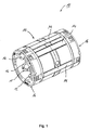
- the Fig. 1 shows by way of illustration a perspective view of a designed as a linear ball bearing 10 conventional linear guide.
- the conventional linear guide 10 includes one in the Fig. 1 not shown shaft as an inner guide member, and a sleeve surrounding the shaft cylindrical 11, which is also referred to below as a cage.
- the bush or the cage 11 in turn comprises a plurality of endless Wälz stresses- or ball circuits 12.
- An endless ball circulation 12 is formed by a ball channel, which can be divided into a flow or load / support channel and a return channel. In the flow channel is in each case one (during operation) currently bearing ball row, ie those balls 13 which support the cylindrical cage 11 relative to the shaft.
- the balls 13 located in the feed channel roll between a raceway formed by the shaft surface and a mating track 14 located on the side of the cage or the bush 11.
- bearing assembly 10 are housed in end rings 16, the balls 13 can be deflected from the flow channel into a corresponding load-free return passage of the cage 11 be, and vice versa. This results in an endless recirculating ball in the ball guide channel 12.
- the bearing assembly 10 can be sealed by means of seals located on the end rings 16 against an external environment.
- In the deflecting or closing rings 16 can also be lubricant deposits for lubrication of the rolling elements 13.
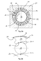
- the Fig. 2a shows a cross-sectional view of the linear guide assembly 10 according to Fig. 1 , which is installed in a housing 21.
- a total of six ball guide channels 22 can be seen, each of which in turn can be divided into flow and support channels 23 and return channels 24.
- the rolling elements or balls 13 roll between roller tracks 25, which are formed by the shaft surface of the shaft 26, and mating tracks 27 from.
- the mating tracks 27 are formed by fitted into the cage 11 track pieces or inserts 14, which may be made of hardened steel, for example.
- the guided in the flow channel 23 rolling elements 13 are by means of the basis of Fig. 1 deflecting regions 15 described deflected in a corresponding return channel 24, in which they are returned unloaded during operation of the linear guide 10, in turn, then enter the flow channel 23.
- the Fig. 2b shows an enlarged cross-sectional view of a ball feed channel 23, in which a ball 13 rolls between the shaft 26 and the raceway 14 inserted into the cage 11.
- the cylindrical cage 11 is located together with the track pieces 14 in a housing bore of the bearing housing 21.
- a cylindrical inner surface of the housing bore is in the Fig. 2b provided with the reference numeral 28.
- the career or the run web piece 14 has a circumferential balls 13 facing and concave shaped raceway surface 29.
- the concave or curved raceway surface 29 extends conventionally in cross-section arcuate, ie round.
- a curvature of the raceway surface 29 is less pronounced than a curvature of the spherical surface of the ball 13, which rolls between the raceway surface 29 and the surface of the shaft 26. Due to the lower curvature of the raceway surface 29 in comparison to the ball surface, two defined contact points between the ball 13, the shaft surface and the ball-facing raceway surface 29 result in the loaded state.
- the two defined contact points in the flow channel 23 are denoted by the reference numerals 30-1 and 30 -2 provided.
- one of the housing bore facing, radially outer surface 31 of the raceway 14 is adapted in its contour of the surface 28 of the housing bore.
- a curvature of the radially outer surface 31 of the track is equal to a curvature of the cylindrical housing bore.
- This predefined 2-point contact between ball and raceway (or 3-point contact, if the shaft is also taken into account) can increase the load capacity of the linear bearing or the linear guide.
- exemplary embodiments provide a correspondingly designed raceway for a linear guide.
- the linear guide comprises an inner guide part in the form of a shaft and an outer guide part comprising a cage.
- the outer and inner guide parts, d. H. that is, the cage and the shaft are movable relative to each other in the direction of the shaft axis by means of circulating balls in the cage.
- the track of the Linearfiihrung has a (in operation) rotating balls facing raceway surface on which the balls between the raceway surface and a surface of the shaft can roll during operation of the linear guide.
- the ball facing (ie, radially inner) raceway surface is formed such that on the raceway surface for a rolling off between the raceway surface and the shaft surface ball two predefined and circumferentially spaced ball contact areas or points are provided, where the Unroll ball.
- Predefined here means that the two contact areas do not arise randomly during operation, but that they are deliberately formed beforehand as predetermined contact areas or surfaces for circulating balls.
- the radially inner raceway surface is shaped such that exactly two predefined contact areas or points for the revolving balls are provided by their geometry during operation of the linear guide. Together with a contact point for a rotating ball on the shaft then arise for the ball then exactly three contact points in the ball supply passage during the ball circulation.
- This 3-point contact in the flow channel during operation between a rotating ball, the shaft and the mating track in the cage has a positive effect on a load rating of the linear guide.
- embodiments of the present invention can thus increase load ratings of linear ball bearings.
- the raceway surface of the (counter) track facing the balls which rotate during operation is substantially concave. That is, the raceway surface is curved so as to partially encircle a circumferential ball in the circumferential direction to guide it.
- Concavely curved includes, in cross-section perpendicular to the shaft axis, also straight-lined raceway surface portions.
- the raceway surface may have raceway surface portions protruding and recessed backward in a radial direction toward the ball, the two predefined contact areas of the raceway surface being formed by raceway surface portions at least partially projecting and circumferentially spaced from one another.
- Embodiments of the present invention include various track geometries that provide protruding and recessed track surface sections, respectively.
- the track in a plane perpendicular to an axial extent (corresponding to the longitudinal axis) of the linear guide or the raceway a polygonal cross-section, such as. B. have a partially polygonal cross-section.
- the concave raceway surface is in accordance with The embodiments not round but polygonal running with flat raceway surface sections.
- Some examples see z. B. three flat and parallel to the longitudinal direction of the track extending track surface sections, of which two flat Laufbahnobervidabexcellente the rotating balls tangential.D. That is, the two raceway surface sections, which include the two predefined contact areas are tangential surface portions which tangent to the spherical surface of a circulating in operation Ball run.
- the raceway surface facing the balls may have a substantially circular cross-section in a plane perpendicular to the axial extent of the raceway, with projections arranged circumferentially along the raceway surface at predefined intervals and serving as contact areas, radially inwardly facing projections.
- the two projecting raceway surface portions, i. H. the protrusions serving as the two contact surfaces are convex, for example, whereas the other recessed raceway surface portions may be concavely curved.
- the exactly two predefined and in the circumferential direction of the ball spaced contact areas or contact surfaces of the raceway surface are preferably arranged symmetrically to a running in the radial direction axis of symmetry of the track or a rolling ball on the track.
- a track according to the invention is used in particular for linear ball guides, in which the outer guide member or the cage is formed as a cylindrical sleeve which can be received by a cylindrical housing bore.
- the (counter) track can be inserted into the cylindrical bushing or the cage in such a way that the raceway surface facing the revolving balls points radially into the interior of the cage, that is to say in the direction of the shaft.
- One of the housing bore facing, ie radially outwardly facing surface of the track has, according to embodiments, a greater curvature than the housing bore.
- Exemplary embodiments therefore provide a track for a linear guide with an inner guide part formed as a shaft and a cage designed as a cylindrical bushing as the outer guide part.
- the cage is movable relative to the shaft by means of circulating balls in the cage.
- the cylindrical bushing or cage can be received by a cylindrical bearing housing bore.
- the raceway can be inserted into the cage formed by the cylindrical bushing such that a raceway surface facing the revolving balls, on which the balls can roll between the raceway and a surface of the shaft, points radially inward of the bushing.
- the track is designed such that two predefined contact areas which are spaced apart from one another in the circumferential direction of the ball are provided on the raceway surface facing the revolving balls (radially inner raceway surface) for a ball rolling between the track surface and the surface of the shaft can.
- one of the bearing housing bore facing (radially outer) raceway surface has a greater curvature than the cylindrical bearing housing bore, so that forms a linear contact area between the raceway and the bearing housing bore when inserting the cylindrical sleeve with the raceway inserted therein in the bearing housing bore.
- a line-shaped contact area between the outer raceway side and the housing bore can form during the introduction of the cylindrical bushing with the raceway into the housing bore.
- this in turn means a defined contact point between the raceway outside and housing bore.
- the curvature of the tread outside can be adapted to a smallest bearing size, and thus to a smallest housing diameter.
- For larger housing diameter then results when inserting the cage along with career described one-point or one-line contact between the raceway outside and housing bore. This allows for easier measuring of the track thickness and more reliable automation in an assembly machine.
- An influence of track thickness variations in the same ball sorting and an influence on the desired operating clearance can be minimized by embodiments.
- a linear guide is proposed with a cage designed as a cylindrical bush, in which at least one inventive track is used, wherein the cage with the at least one used or recorded raceway is mounted in the cylindrical bearing housing bore.
- the cage is thus installed in the housing bore, ie, is in the installed state.
- a stable 3-point position for a revolving ball results during operation of the ball guides.
- a stable 3-point position for the career Due to the proposed two-point contact between the ball and raceway a load rating can be increased, which in turn can result in longer lifetimes, especially for longer strokes of linear guides.
- load ratings allow embodiments lower hardness of the raceway material, resulting in a larger selection of base materials such. As drawing steels, results for careers. Softer base materials in turn allow easier processing of the raceway profiles, z. B. a processing of the inlet contour.
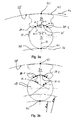
- the Fig. 3a shows an enlarged cross-sectional view of a flow channel of a linear guide according to the invention (linear ball bearing), wherein a ball 13 between a shaft 26 and a (counter) track 34 of the linear guide is guided.
- a cage which receives the (counter) track 34, not shown.
- the raceway 34 has a raceway surface 35 (ie radially inward) facing the revolving ball 13, on which the ball 13 can roll between the raceway surface 35 and a shaft surface 36 during operation of the linear guide.
- raceway surface 35 is formed such that on the raceway surface 35 for a rolling off between the raceway surface 35 and the shaft surface 36 ball 13 two predefined and circumferentially 37 of the ball spaced contact areas and points 38-1 and 38-2 are provided, on which the ball 13 can roll in the axial direction.
- An exact location of the contact points 38-1 and 38-2 is determined by the geometry of the raceway surface 35 and the ball diameter.
- the two predefined contact areas 38-1 and 38-2 are predefined contact points of the ball 13 with the raceway surface 35.
- these contact points 38-1 and 38 travel with the ball along the track 34 -2 each one substantially straight Line on the raceway surface 35 along the longitudinal or extension direction of the raceway 34.
- the raceway surface 35 in a plane perpendicular to the axial extent of the track 34 has a polygonal, in particular partially polygonal cross-section.
- the raceway surface 35 in the illustrated form has three planar raceway surface sections 35-1, 35-2 and 35-3, all of which are arranged parallel to the longitudinal axis or extension direction of the raceway 34 (into the plane of the drawing).
- the raceway surface 35 may thus according to some embodiments in a plane perpendicular to an axial extent of the track 34 have a polygonal, in particular partially polygonal, cross-section, so that the two contact portions 38-1, 38-2 by parallel to a longitudinal axis of the track 34 polygonal arranged, planar raceway surface portions 35-1 and 35-3 are formed.
- the tread 35 may thus be formed as a symmetrical polygonal channel with flat boundary surfaces 35-1, 35-2 and 35-3, two of which (35-1 and 35-3) provide the contact points 38-1 and 38-2.
- the three raceway surface sections 35-1 to 35-3 are arranged in an axisymmetric manner with respect to a radially extending symmetry axis 39 through the ball 13 or the raceway 34. While the middle surface portion 35-2 extends substantially perpendicular to the axis of symmetry 39, the two outer planar raceway surface portions 35-1 and 35-3 are disposed obliquely therewith, comparable to legs of an isosceles triangle.
- the two planar and sloping raceway surface portions 35-1 and 35-3 may, according to some embodiments, form tangential surface portions for the ball 13 encircling the race 34, the tangential surface portions 35-1 and 35-3 tangent to the spherical surface in the loaded condition of the bearing. More generally, therefore, the raceway surface 35 has (at least partially) projecting raceway surface portions 35-1 and 35-3 in a radial direction facing the ball 13 and a raceway surface portion 35-2 radially recessed.
- the two predefined contact areas 38-1 and 38-2 are formed by the raceway surface portions 35-1 and 35-3 projecting in the radial direction opposite to the tread portion 35-2 and circumferentially spaced from each other.
- Connecting lines 40-1 and 40-3 between a center of the revolving ball 13 and the contact points 38-1 and 38-2 close with the axis of symmetry 39 each have an angle ⁇ .
- the angle ⁇ depends, in addition to an inclination angle ⁇ of the two inclined tread portions 35-1, 35-3 with respect to the axis of symmetry 39, from an available space for the linear guide or a diameter of the rotating balls 13.
- Embodiments of the present invention provide geometries in which the angle ⁇ is preferably in a range of 20 ° to 45 °.
- the angle ⁇ is preferably in a range of 20 ° to 45 °.
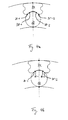
- the raceway surface 35 may also be substantially circular in a plane perpendicular to the axial extent of the raceway 34, with projections arranged circumferentially 37 along the raceway surface at predefined intervals and serving as contact areas in the direction of ball 13 (see FIG Fig. 4a ).
- the projecting raceway surface portions ie the projections, which serve as contact surfaces, for example, may be convex, whereas the other recessed raceway surface portions may be cylindrically shaped or concave (in FIG Fig. 4a not shown).
- prismatic contact surfaces 35-1, 35-3 instead of in the Fig. 3a shown straight, prismatic contact surfaces 35-1, 35-3 also a so-called gothic (ogival) profile can be used to allow a further increase in the load ratings (see Fig. 4b ).
- the raceway 34 On a radially outwardly facing side, the raceway 34 has an outer raceway surface 42 which is more curved than the surface 28 of the cylindrical housing bore. Due to these different degrees of curvature of the surfaces 42nd and 28 also results in a defined contact point 43 between the track 34 and the housing bore in cross section. "Curvature” is to be understood in the context of the present invention, a measure of the deviation of a surface of a tangent through the contact point 43. That is, as viewed in the circumferential direction 44 of the housing bore, soft spots on the outer raceway surface 42 are more distinct from the tangent through the point 43 than points on the housing bore surface 28. That is, a circle defining the outer raceway surface 42.
- the curvatures of the two surfaces 28 and 42 preferably do not differ by more than 40%.
- the curvature k B of the housing bore surface 28 deviates by no more than 40% from the curvature k L of the outer raceway surface 42, ie 0.6 k L ⁇ k B ⁇ k L or k B ⁇ k L ⁇ 1.4 k B.
- a difference of the two curvatures may be in a range below 20%. It is important that the two curvatures differ, not only because of manufacturing tolerances. That is, a difference of the two curvatures (starting from k B or k L ) should be at least 5%, preferably at least 10% and more preferably at least 15%.
- the hatched area 51 shows a curvature area in which the curvature k L of the upper raceway surface 42 should lie, so that the construction and its function remain stable.
- a raceway opening angle ⁇ depends on several factors, but mainly on the size of the linear bearing, ie, the size of the ball 13, width of the raceway 34, etc.
- the raceway opening angle ⁇ indirectly influences the raceway radius R L. The smaller the raceway opening angle ⁇ becomes, the smaller becomes a minimum raceway radius R L, min .
- a width b of the track 34 is crucial for the stable 2-point contact between ball 13 and track 34.
- the width of the extension of the stable zone 51 is limited by means of the outermost contact point of the ball 13 in the prism formed by the raceway surface 35.
- the minimum track radius R L, min can be defined by a height h, which in turn is the distance from the center of the ball and the contact point 43 of the track 34 to the housing bore. Only if h1 (ie the track radius R L ) is greater than h, the construction will always aim for a stable position. This means that the track radius R L , which defines the curvature k L , should lie between a radius R G of the housing bore and the distance h from the center of the sphere and to the contact point 43.
- Center points of arcs with the different radii are all on the axis 39. This allows the track 34 center itself, regardless of the radius R w of the shaft 26 and the radius R G of the bearing housing, as long as these two have a common origin. This is always the case. Even if both radii R w and R G should be infinite. In other words, a radial height h1 of the raceway 34 in the direction "hx" from the middle of the raceway should always be greater than h. Then theoretically, the angle career opening angle ⁇ can be up to 180 °.
- the construction remains stable and will center itself when in the entire system of linear bearings in the housing on a shaft with at least three raceways 34 (see Fig. 5b ) arise due to operating loads certain elastic deformations.
- the Fig. 3b shows the use of a track 34 according to the invention for different sized shaft diameter D1 and D2, which lead at the same housing bore to different sized ball diameters d1 and d2.
- the position of the contact point 43 does not change, so that in both cases the same track 34, but with different balls, can be used as long as the ball always two contact points 38-1, 38-2 with the Track has and the outer curvature of the track 34 still produces a line contact with the housing bore.
- aspects have been described in the context of a device or a linear guide, it is understood that these aspects also represent a description of a corresponding method, in particular an operating or manufacturing method, so that a block or a component of a device as a corresponding Process step or as a feature of a process step, for example, for the production or operation of a linear guide to understand.
- aspects described in connection with or as a method step also represent a description of a corresponding block or detail or feature of a corresponding device.
Landscapes
- Engineering & Computer Science (AREA)
- General Engineering & Computer Science (AREA)
- Mechanical Engineering (AREA)
- Bearings For Parts Moving Linearly (AREA)
Abstract
Description
Ausführungsbeispiele der vorliegenden Erfindung betreffen Linearführungen und insbesondere Laufbahnen von Kugelkanälen bei derartigen Linearführungen.Embodiments of the present invention relate to linear guides and in particular raceways of ball channels in such linear guides.
Unter einer Linearführung versteht man im Allgemeinen eine Anordnung, die eine möglichst reibungsfreie Translation einer oder mehrerer beweglicher Baugruppen einer Maschine ermöglicht und dabei gleichzeitig eine Einhaltung der Bewegungsrichtung in Form einer linearen Bahn garantiert. Man kann Linearführungen nach ihrer Lagerung grundsätzlich in Gleitfiihrungen und Wälzfiihrungen unterteilen. Wälzfiihrungen beruhen auf dem Prinzip der Umwälzung von Wälzkörpern zwischen zwei relativ zueinander bewegten Führungselementen bzw. -teilen. Als Wälzkörper können, wie bei einem Rotationswälzlager, beispielsweise Kugeln, Rollen, Nadeln oder andere Wälzkörper dienen. Zu den Wälzfiihrungen gehören beispielsweise Profilschienenführungen oder Linearkugellager, welche auch als Kugelbuchsen bezeichnet werden können. Hierbei sind Linearführungen nicht ausschließlich auf lineare Bewegungen beschränkt. Sie ermöglichen vielmehr eine translatorische Bewegung im Vergleich zu rotatorischen Bewegungen, die durch entsprechende Rotationswälzlager geführt werden. Gerade im Bereich der Linearlager werden die Begriffe "linear" und "translatorisch" daher häufig synonym verwendet.A linear guide is generally understood to mean an arrangement which allows the most frictionless possible translation of one or more movable subassemblies of a machine and at the same time guarantees compliance with the direction of movement in the form of a linear path. After storage, linear guides can basically be subdivided into sliding guides and roller guides. Wälzfiihrungen based on the principle of circulation of rolling elements between two relatively moving guide elements or parts. As rolling elements, as in a rotary rolling bearing, for example, balls, rollers, needles or other rolling elements serve. The Wälzfiihrungen include, for example, profile rail guides or linear ball bearings, which can also be referred to as ball bushings. Here linear guides are not limited to linear movements. Rather, they allow a translational movement in comparison to rotary movements, which are guided by corresponding rotary bearings. Especially in the field of linear bearings, the terms "linear" and "translational" are therefore often used interchangeably.
Mit Hilfe von Linearführungen lassen sich präzise Translationsbewegungen in vielfältigen Anwendungssituationen realisieren. Eine Linearführung weist im Allgemeinen eine Führungsschiene, wie z. B. eine Welle oder eine Profilschiene, und einen Linear- bzw. Führungswagen auf, der, gemäß manchen Ausführungsformen, insbesondere bei Linearkugellagern, auch als zylindrische Buchse ausgebildet sein kann, und welcher linear beweglich auf der Führungsschiene angeordnet ist. Insbesondere bei Anwendungssituationen, bei denen eine Amplitude der Linearbewegung in einer Größenordnung der Außenabmessungen des Führungswagens parallel zur Bewegungsrichtung liegt oder diese sogar übersteigt, werden häufig so genannte Kugelumlauffiihrungen eingesetzt. Eine Kugelumlauffiihrung zeichnet sich dadurch aus, dass der Führungswagen mittels Kugeln relativ zur Führungsschiene beweglich gelagert ist und dass die Kugeln auf einer geschlossenen, also quasi endlosen, Bahn umlaufen. Eine Kugelumlauffiihrung ermöglicht somit eine beliebige lineare Beweglichkeit des Führungswagens relativ zu Führungsschiene, die nur durch die Abmessungen der Führungsschiene und gegebenenfalls durch eine Einbauumgebung begrenzt wird.With the aid of linear guides, precise translational movements can be realized in a wide variety of application situations. A linear guide generally has a guide rail, such. As a wave or a rail, and a linear or guide carriage, which, according to some embodiments, in particular in linear ball bearings, may also be formed as a cylindrical sleeve, and which is arranged linearly movable on the guide rail. Especially in application situations in which an amplitude of the linear movement in an order of magnitude of the outer dimensions of the guide carriage is parallel to or even exceeds the direction of movement, so-called Kugelumlauffiihrungen are often used. A Kugelumlauffihrung is characterized in that the carriage is mounted by means of balls movable relative to the guide rail and that the balls rotate on a closed, so quasi-endless, web. A Kugelumlauffiihrung thus allows any linear mobility of the guide carriage relative to the guide rail, which is limited only by the dimensions of the guide rail and possibly by an installation environment.
Bei den auch als Kugelbuchsen bezeichneten Linearkugellagern umgreift typischerweise ein als zylindrische Buchse ausgebildeter Führungswagen oder Käfig mit einem im Wesentlichen zylindrischen Querschnitt eine als Führungsschiene wirkende, insbesondere runde, Welle, weshalb diese spezielle Form der Linearführung auch als Wellenfiihrung bezeichnet werden kann. Dabei ist die Buchse auf der Welle wälzgelagert, sodass sie einen äußeren Führungsteil des Linearkugellagers bildet, während die Welle einen inneren Führungsteil des Linearkugellagers bildet.When referred to as ball bushings linear ball bearings typically surrounds designed as a cylindrical bushing carriage or cage with a substantially cylindrical cross-section acting as a guide rail, in particular round shaft, which is why this special form of linear guide can also be referred to as Wellenfiihrung. In this case, the sleeve is roller-mounted on the shaft, so that it forms an outer guide part of the linear ball bearing, while the shaft forms an inner guide part of the linear ball bearing.
Die
Die herkömmliche Linearführung 10 umfasst eine in der
Die
In der Querschnittsdarstellung der
Gemäß der in der
Die
Des Weiteren lässt sich aus der
Es sind also Linearlager bekannt, deren Laufbahnkonturen nach außen einer Kontur der Gehäusebohrung und nach innen dem Kugeldurchmesser (Schmiegung mit einem herkömmlichen 1-Punkt-Kontakt) angepasst sind. Aus wirtschaftlichen Gründen werden oftmals gleiche Laufbahnprofile für mehrere Lagerbaugrößen eingesetzt. In solchen Fällen ist es notwendig, aufgrund der Kombination Laufbahnprofil mit kleinerer Kugel (wegen kleineren Baugrößen der Linearlager) und der daraus resultierenden größeren Schmiegung Tragzahlverluste zu akzeptieren. Dabei entsteht ein weiterer Nachteil für die abgeleiteten, kleineren Kugelreihen. Da die Laufbahnkontur auf der Außenseite nicht der Gehäusebohrung entspricht, ist eine Ermittlung der Kugelsortierung und die Abstimmung des Betriebsspiels erschwert. Größere Schwankungen im umfangreichen Fertigungsprozess der Laufbahnen, der z. B. Ziehen, Richten, Ablängen, Härten und Trowalisieren umfasst, können schnell zu Qualitätsproblemen des Endprodukts bzw. zu Reklamationen führen.So linear bearings are known whose career contours are adapted to the outside of a contour of the housing bore and inwardly the ball diameter (osculation with a conventional 1-point contact). For economic reasons, the same track profiles are often used for several bearing sizes. In such cases it is necessary, due to the combination of raceway profile with a smaller ball (due to smaller sizes of linear bearings) and the resulting greater osculation to accept load factor losses. This creates a further disadvantage for the derived, smaller rows of balls. Since the raceway contour on the outside does not correspond to the housing bore, a determination of the ball sorting and the tuning of the operating clearance is difficult. Larger fluctuations in the extensive manufacturing process of the raceways, the z. As pulling, straightening, cutting to length, hardening and Trowalisieren included, can quickly lead to quality problems of the final product or to complaints.
Es ist daher eine Aufgabe der vorliegenden Erfindung, ein verbessertes Konzept für kugelgelagerte Linearführungen bereitzustellen.It is therefore an object of the present invention to provide an improved concept for ball-bearing linear guides.
Diese Aufgabe wird gelöst durch eine Laufbahn für eine Linearführung mit den Merkmalen des Anspruchs 1, einer Linearführung gemäß Anspruch 9 und einem Verfahren zum Betreiben einer Linearführung gemäß Anspruch 10.This object is achieved by a track for a linear guide with the features of claim 1, a linear guide according to claim 9 and a method for operating a linear guide according to
Es ist ein Kerngedanke der vorliegenden Erfindung, ein Abrollverhalten einer Kugel in einem Vorlaufkanal einer Linearführung zu verbessern, indem während des Betriebs der Linearführung, d. h. unter Last, ein definierter 3-Punkt-Kontakt zwischen einer umlaufenden Kugel, einer Welle und einer (Gegen-) Laufbahn im Käfig geschaffen wird. In anderen Worten ausgedrückt bedeutet dies einen 2-Punkt-Kontakt zwischen einer im Vorlaufkanal umlaufenden Kugel und der am Käfig angeordneten Laufbahn. Durch diesen vordefinierten 2-Punkt-Kontakt zwischen Kugel und Laufbahn (bzw. 3-Punkt-Kontakt, wenn man zusätzlich die Welle berücksichtigt) kann eine Tragzahl des Linearlagers bzw. der Linearfiihrung erhöht werden.It is a core idea of the present invention to improve a rolling behavior of a ball in a flow channel of a linear guide, during operation of the linear guide, i. H. under load, a defined 3-point contact between a rotating ball, a shaft and a (counter) career is created in the cage. In other words, this means a 2-point contact between a circulating in the flow channel ball and the cage arranged on the track. This predefined 2-point contact between ball and raceway (or 3-point contact, if the shaft is also taken into account) can increase the load capacity of the linear bearing or the linear guide.
Dazu sehen Ausführungsbeispiele eine entsprechend ausgebildete Laufbahn für eine Linearfiihrung vor. Die Linearführung umfasst einen als Welle ausgebildeten inneren Führungsteil und einen Käfig umfassendes äußeres Führungsteil. Das äußere und das innere Führungsteil, d. h. also der Käfig und die Welle, sind vermittels in dem Käfig umlaufender Kugeln relativ zueinander in Richtung der Wellenachse beweglich. Die Laufbahn der Linearfiihrung weist eine (im Betrieb) umlaufenden Kugeln zugewandte Laufbahnoberfläche auf, auf welcher die Kugeln zwischen der Laufbahnoberfläche und einer Oberfläche der Welle während des Betriebs der Linearführung abrollen können. Dabei ist die den Kugeln zugewandte (d.h. radial innen liegende) Laufbahnoberfläche derart ausgebildet, dass an der Laufbahnoberfläche für eine zwischen der Laufbahnoberfläche und der Wellenoberfläche abrollende Kugel zwei vordefinierte und in Umfangsrichtung der Kugel voneinander beabstandete Kontaktbereiche bzw. -punkte bereitgestellt werden, an denen die Kugel abrollen kann. "Vordefiniert" meint hier, dass die beiden Kontaktbereiche sich während des Betriebs nicht zufällig ergeben, sondern dass sie vorab bewusst als vorbestimmte Kontaktbereiche bzw. -flächen für umlaufende Kugeln ausgebildet werden.For this purpose, exemplary embodiments provide a correspondingly designed raceway for a linear guide. The linear guide comprises an inner guide part in the form of a shaft and an outer guide part comprising a cage. The outer and inner guide parts, d. H. that is, the cage and the shaft are movable relative to each other in the direction of the shaft axis by means of circulating balls in the cage. The track of the Linearfiihrung has a (in operation) rotating balls facing raceway surface on which the balls between the raceway surface and a surface of the shaft can roll during operation of the linear guide. Here, the ball facing (ie, radially inner) raceway surface is formed such that on the raceway surface for a rolling off between the raceway surface and the shaft surface ball two predefined and circumferentially spaced ball contact areas or points are provided, where the Unroll ball. "Predefined" here means that the two contact areas do not arise randomly during operation, but that they are deliberately formed beforehand as predetermined contact areas or surfaces for circulating balls.
Dabei ist die radial innen liegende Laufbahnoberfläche derart geformt, dass durch ihre Geometrie im Betrieb der Linearführung genau zwei vordefinierte Kontaktbereiche bzw. - punkte für die umlaufenden Kugeln bereitgestellt werden. Zusammen mit einem Kontaktpunkt für eine umlaufende Kugel auf der Welle ergeben sich für die Kugel dann genau drei Kontaktstellen im Kugelvorlaufkanal während des Kugelumlaufs. Dieser 3-Punkt-Kontakt im Vorlaufkanal während des Betriebs zwischen einer umlaufenden Kugel, der Welle und der Gegenlaufbahn im Käfig wirkt sich positiv auf eine Tragzahl der Linearführung aus. In anderen Worten ausgedrückt können durch Ausführungsbeispiele der vorliegenden Erfindung Tragzahlen von linearen Kugelführungen also erhöht werden.In this case, the radially inner raceway surface is shaped such that exactly two predefined contact areas or points for the revolving balls are provided by their geometry during operation of the linear guide. Together with a contact point for a rotating ball on the shaft then arise for the ball then exactly three contact points in the ball supply passage during the ball circulation. This 3-point contact in the flow channel during operation between a rotating ball, the shaft and the mating track in the cage has a positive effect on a load rating of the linear guide. In other words, embodiments of the present invention can thus increase load ratings of linear ball bearings.
Betrachtet man eine erfindungsgemäße Linearführung im Querschnitt senkrecht zur Wellenachse, so sehen Ausführungsbeispiele also genau zwei vordefinierte und in Umfangsrichtung der umlaufenden Kugel voneinander beabstandete Kontaktpunkte an der Laufbahnoberfläche der (Gegen-) Laufbahn vor und einen zusätzlichen Kontaktpunkt zwischen umlaufender Kugel und Welle. Das bedeutet, dass die beiden vordefinierten Kontaktbereiche an der Laufbahnoberfläche derart ausgebildet sind, dass die Kugel im Betrieb der Linearführung beim Abrollen mit den zwei Kontaktbereichen jeweils eine im Wesentlichen gerade verlaufende Linie auf der ihr zugewandten Laufbahnoberfläche der Gegenlaufbahn im Käfig beschreibt.If you consider a linear guide according to the invention in cross section perpendicular to the shaft axis, so see embodiments exactly two predefined and in the circumferential direction of the rotating ball spaced contact points on the raceway surface of the (counter) career before and an additional contact point between the rotating ball and shaft. This means that the two predefined contact areas are formed on the raceway surface in such a way that during operation of the linear guide when rolling with the two contact areas each describes a substantially straight line on the facing raceway surface of the mating track in the cage.
Die den im Betrieb umlaufenden Kugeln zugewandte Laufbahnoberfläche der (Gegen-) Laufbahn ist im Wesentlichen konkav ausgebildet. Das heißt, die Laufbahnoberfläche ist derart gekrümmt, dass sie eine umlaufende Kugel in Umfangsrichtung teilweise umschließt, um sie zu führen."Konkav gekrümmt" umfasst dabei im Querschnitt senkrecht zur Wellenachse auch abschnittsweise gerade verlaufende Laufbahnoberflächenabschnitte. Generell kann die Laufbahnoberfläche in einer zur Kugel weisenden radialen Richtung vorstehende und demgegenüber zurückversetzte Laufbahnoberflächenabschnitte aufweisen, wobei die beiden vordefinierten Kontaktbereiche der Laufbahnoberfläche durch radial zumindest teilweise vorstehende und in Umfangsrichtung voneinander beabstandet angeordnete Laufbahnoberflächenabschnitte gebildet werden.The raceway surface of the (counter) track facing the balls which rotate during operation is substantially concave. That is, the raceway surface is curved so as to partially encircle a circumferential ball in the circumferential direction to guide it. "Concavely curved" includes, in cross-section perpendicular to the shaft axis, also straight-lined raceway surface portions. Generally, the raceway surface may have raceway surface portions protruding and recessed backward in a radial direction toward the ball, the two predefined contact areas of the raceway surface being formed by raceway surface portions at least partially projecting and circumferentially spaced from one another.
Ausführungsbeispiele der vorliegenden Erfindung umfassen verschiedene Laufbahngeometrien, welche vorstehende und demgegenüber zurückversetzte Laufbahnoberflächenabschnitte bereitstellen. Gemäß manchen Ausführungsbeispielen kann die Laufbahn in einer Ebene senkrecht zu einer axialen Erstreckung (entsprechend der Längsachse) der Linearführung bzw. der Laufbahn einen mehreckigen Querschnitt, wie z. B. einen teilweise polygonalen Querschnitt, aufweisen. Das bedeutet, die konkave Laufbahnoberfläche wird gemäß den Ausführungsbeispielen nicht rund, sondern mehreckig mit ebenen Laufbahnoberflächenabschnitten ausgeführt. Dabei sehen manche Ausführungsbeispiele z. B. drei ebene und parallel zur Längsrichtung der Laufbahn verlaufende Laufbahnoberflächenabschnitte vor, wobei davon zwei ebene Laufbahnoberflächenabschnitte die umlaufenden Kugeln tangential führen.Das heißt, die beiden Laufbahnoberflächenabschnitte, welche die beiden vordefinierten Kontaktbereiche umfassen, sind Tangentialflächenabschnitte, welche tangential zur Kugeloberfläche einer im Betrieb umlaufenden Kugel verlaufen.Embodiments of the present invention include various track geometries that provide protruding and recessed track surface sections, respectively. According to some embodiments, the track in a plane perpendicular to an axial extent (corresponding to the longitudinal axis) of the linear guide or the raceway a polygonal cross-section, such as. B. have a partially polygonal cross-section. This means that the concave raceway surface is in accordance with The embodiments not round but polygonal running with flat raceway surface sections. Some examples see z. B. three flat and parallel to the longitudinal direction of the track extending track surface sections, of which two flat Laufbahnoberflächenabschnitte the rotating balls tangential.D. That is, the two raceway surface sections, which include the two predefined contact areas are tangential surface portions which tangent to the spherical surface of a circulating in operation Ball run.
Gemäß anderen Ausführungsbeispielen kann die den Kugeln zugewandte Laufbahnoberfläche in einer Ebene senkrecht zur axialen Erstreckung der Laufbahn einen im Wesentlichen runden Querschnitt aufweisen, mit in Umfangsrichtung entlang der Laufbahnoberfläche in vordefinierten Abständen angeordneten und als Kontaktbereiche dienenden radial nach innen weisenden Vorsprüngen. Bei solchen Ausführungsbeispielen sind die beiden vorstehenden Laufbahnoberflächenabschnitte, d. h. die Vorsprünge, welche als die beiden Kontaktflächen dienen, beispielsweise konvex ausgebildet, wohingegen die übrigen zurückversetzten Laufbahnoberflächenabschnitte konkav gekrümmt geformt sein können.According to other embodiments, the raceway surface facing the balls may have a substantially circular cross-section in a plane perpendicular to the axial extent of the raceway, with projections arranged circumferentially along the raceway surface at predefined intervals and serving as contact areas, radially inwardly facing projections. In such embodiments, the two projecting raceway surface portions, i. H. the protrusions serving as the two contact surfaces are convex, for example, whereas the other recessed raceway surface portions may be concavely curved.
Die genau zwei vordefinierten und in Umfangsrichtung der Kugel voneinander beabstandeten Kontaktbereiche bzw. Kontaktflächen der Laufbahnoberfläche sind vorzugsweise symmetrisch zu einer in radialer Richtung verlaufenden Symmetrieachse der Laufbahn bzw. einer auf der Laufbahn abrollenden Kugel angeordnet. Das bedeutet, dass beispielsweise zwei ebene Laufbahnoberflächenabschnitte, welche Tangentialflächenabschnitte für eine auf der Laufbahn umlaufende Kugel bilden, mit der Symmetrieachse betragsmäßig gleiche Winkel einschließen. Das gilt ebenso für Lote der Tangentialflächenabschnitte durch die jeweiligen Kontaktpunkte zwischen Kugel und Tangentialflächenabschnitt.The exactly two predefined and in the circumferential direction of the ball spaced contact areas or contact surfaces of the raceway surface are preferably arranged symmetrically to a running in the radial direction axis of symmetry of the track or a rolling ball on the track. This means that, for example, two planar raceway surface sections, which form tangential surface sections for a ball rotating on the raceway, enclose equal angles with the symmetry axis in terms of magnitude. This also applies to solders of the tangential surface sections through the respective contact points between sphere and tangential surface section.
Gemäß Ausführungsbeispielen wird eine erfindungsgemäße Laufbahn insbesondere für lineare Kugelführungen eingesetzt, bei denen der äußere Führungsteil bzw. der Käfig als zylindrische Buchse ausgebildet ist, die von einer zylindrischen Gehäusebohrung aufgenommen werden kann. Die (Gegen-) Laufbahn kann dabei derart in die zylindrische Buchse bzw. den Käfig eingesetzt werden, dass die den umlaufenden Kugeln zugewandte Laufbahnoberfläche radial ins Innere des Käfigs, also in Richtung Welle, weist. Eine der Gehäusebohrung zugewandte, d. h. radial nach außen weisende Oberfläche der Laufbahn weist gemäß Ausführungsbeispielen eine größere Krümmung auf als die Gehäusebohrung. Ausführungsbeispiele stellen also eine Laufbahn bereit für eine Linearführung mit einem als Welle ausgebildeten inneren Führungsteil und einem als zylindrische Buchse ausgebildeten Käfig als äußeres Führungsteil. Der Käfig ist relativ zu der Welle vermittels in dem Käfig umlaufender Kugeln beweglich. Die die zylindrische Buchse bzw. der Käfig kann von einer zylindrischen Lagergehäusebohrung aufgenommen werden. Die Laufbahn kann derart in den durch die zylindrische Buchse gebildeten Käfig eingesetzt werden, dass eine den umlaufenden Kugeln zugewandte Laufbahnoberfläche, auf welcher die Kugeln zwischen der Laufbahn und einer Oberfläche der Welle abrollen können, radial ins Innere der Buchse weist. Gemäß Ausführungsbeispielen ist die Laufbahn derart ausgebildet, dass an der den umlaufenden Kugeln zugewandten (radial innere) Laufbahnoberfläche für eine zwischen der Laufbahnoberfläche und der Oberfläche der Welle abrollende Kugel zwei vordefinierte und in Umfangsrichtung der Kugel voneinander beabstandete Kontaktbereiche bereitgestellt werden, an denen die Kugel abrollen kann. Des Weiteren weist eine der Lagergehäusebohrung zugewandte (radial äußere) Laufbahnoberfläche eine größere Krümmung als die zylindrische Lagergehäusebohrung auf, so dass sich beim Einbringen der zylindrischen Buchse mit der darin eingesetzten Laufbahn in die Lagergehäusebohrung ein linienförmiger Kontaktbereich zwischen der Laufbahn und der Lagergehäusebohrung ausbildet. Dadurch kann sich beim Einbringen der zylindrischen Buchse mit der Laufbahn in die Gehäusebohrung ein linienförmiger Kontaktbereich zwischen Laufbahnaußenseite und Gehäusebohrung ausbilden. Im Querschnitt senkrecht zur Wellenachse bedeutet dies wiederum einen definierten Kontaktpunkt zwischen Laufbahnaußenseite und Gehäusebohrung. Dies hat den Vorteil, dass derart geformte Laufbahnen für mehrere Lagergrößen eingesetzt werden können. Beispielsweise kann die Krümmung der Laufflächenaußenseite an eine kleinste Lagergröße, und damit an einen kleinsten Gehäusedurchmesser, angepasst sein. Für größere Gehäusedurchmesser ergibt sich dann beim Einbringen des Käfigs samt Laufbahn der beschriebene Ein-Punkt- bzw. Ein-Linien-Kontakt zwischen Laufbahnaußenseite und Gehäusebohrung. Dies ermöglicht ein einfacheres Messen der Laufbahndicke und eine prozesssicherere Automatisierung in einer Montagemaschine. Ein Einfluss von Laufbahndickenschwankungen bei einer gleichen Kugelsortierung und ein Einfluss auf das gewünschte Betriebsspiel kann durch Ausführungsbeispiele minimiert werden.According to embodiments, a track according to the invention is used in particular for linear ball guides, in which the outer guide member or the cage is formed as a cylindrical sleeve which can be received by a cylindrical housing bore. The (counter) track can be inserted into the cylindrical bushing or the cage in such a way that the raceway surface facing the revolving balls points radially into the interior of the cage, that is to say in the direction of the shaft. One of the housing bore facing, ie radially outwardly facing surface of the track has, according to embodiments, a greater curvature than the housing bore. Exemplary embodiments therefore provide a track for a linear guide with an inner guide part formed as a shaft and a cage designed as a cylindrical bushing as the outer guide part. The cage is movable relative to the shaft by means of circulating balls in the cage. The cylindrical bushing or cage can be received by a cylindrical bearing housing bore. The raceway can be inserted into the cage formed by the cylindrical bushing such that a raceway surface facing the revolving balls, on which the balls can roll between the raceway and a surface of the shaft, points radially inward of the bushing. According to exemplary embodiments, the track is designed such that two predefined contact areas which are spaced apart from one another in the circumferential direction of the ball are provided on the raceway surface facing the revolving balls (radially inner raceway surface) for a ball rolling between the track surface and the surface of the shaft can. Furthermore, one of the bearing housing bore facing (radially outer) raceway surface has a greater curvature than the cylindrical bearing housing bore, so that forms a linear contact area between the raceway and the bearing housing bore when inserting the cylindrical sleeve with the raceway inserted therein in the bearing housing bore. As a result, a line-shaped contact area between the outer raceway side and the housing bore can form during the introduction of the cylindrical bushing with the raceway into the housing bore. In cross-section perpendicular to the shaft axis, this in turn means a defined contact point between the raceway outside and housing bore. This has the advantage that such shaped raceways can be used for multiple bearing sizes. For example, the curvature of the tread outside can be adapted to a smallest bearing size, and thus to a smallest housing diameter. For larger housing diameter then results when inserting the cage along with career described one-point or one-line contact between the raceway outside and housing bore. This allows for easier measuring of the track thickness and more reliable automation in an assembly machine. An influence of track thickness variations in the same ball sorting and an influence on the desired operating clearance can be minimized by embodiments.
Gemäß einem weiteren Aspekt der vorliegenden Erfindung wird eine Linearführung mit einem als zylindrische Buchse ausgebildeten Käfig vorgeschlagen, in welchen wenigstens eine erfindungsgemäße Laufbahn eingesetzt ist, wobei der Käfig mit der wenigstens einen eingesetzten bzw. aufgenommenen Laufbahn in der zylindrischen Lagergehäusebohrung gelagert ist. Der Käfig ist dabei also in die Gehäusebohrung eingebaut, d.h., befindet sich in eingebautem Zustand.According to a further aspect of the present invention, a linear guide is proposed with a cage designed as a cylindrical bush, in which at least one inventive track is used, wherein the cage with the at least one used or recorded raceway is mounted in the cylindrical bearing housing bore. The cage is thus installed in the housing bore, ie, is in the installed state.
Ein weiterer Aspekt sieht ein Verfahren zum Herstellen und/oder Betreiben einer Linearführung vor, mit einem als Welle ausgebildeten inneren Führungsteil und einem als zylindrische Buchse ausgebildeten Käfig als äußeres Führungsteil. Der Käfig ist relativ zu der Welle vermittels in dem Käfig umlaufender Kugeln beweglich. Die zylindrische Buchse bzw. der Käfig kann von einer zylindrischen Lagergehäusebohrung mit einem vorbestimmten Radius aufgenommen werden. Die Laufbahn kann derart in den durch die zylindrische Buchse gebildeten Käfig eingesetzt werden, dass eine den umlaufenden Kugeln zugewandte Laufbahnoberfläche, auf welcher die Kugeln zwischen der Laufbahn und einer Oberfläche der Welle während eines Betriebs der Linearführung abrollen können, radial ins Innere der Buchse weist. Gemäß Ausführungsbeispielen umfasst das Verfahren folgende Schritte:
- Bereitstellen der Laufbahn, sodass an der den umlaufenden Kugeln zugewandten Laufbahnoberfläche für eine zwischen der Laufbahnoberfläche und der Oberfläche der Welle abrollende Kugel zwei vordefinierte und in Umfangsrichtung der Kugel voneinander beabstandete Kontaktbereiche bereitgestellt werden, an denen die Kugel abrollen kann, und sodass eine der Lagergehäusebohrung zugewandte Oberfläche der Laufbahn eine größere Krümmung als die zylindrische Lagergehäusebohrung aufweist, sodass sich beim Einbringen der zylindrischen Buchse mit der Laufbahn in die Lagergehäusebohrung ein linienförmiger Kontakt zwischen Laufbahn und Lagergehäusebohrung ausbilden kann,
- Einsetzen der Laufbahn in den als zylindrische Buchse ausgebildeten Käfig, und
- Einbringen des zylindrischen Käfigs mit der darin befindlichen Laufbahn in die zylindrische Lagergehäusebohrung, sodass sich zwischen der der Lagergehäusebohrung zugewandten Oberfläche der Laufbahn und der Lagergehäusebohrung der linienförmige Kontakt zwischen Laufbahn und Lagergehäusebohrung ergibt.
- Providing the race so that two predefined and circumferentially spaced ball contact areas are provided on the raceway surface facing the revolving balls for a ball rolling between the raceway surface and the surface on which the ball can roll, and so that one of the bearing housing bores facing Surface of the track has a greater curvature than the cylindrical bearing housing bore, so that when inserting the cylindrical sleeve with the raceway in the bearing housing bore a linear contact between the raceway and bearing housing bore can form,
- Inserting the track in the cage formed as a cylindrical socket, and
- Introducing the cylindrical cage with the raceway therein in the cylindrical bearing housing bore, so that between the bearing housing bore facing surface of the raceway and the bearing housing bore of the linear contact between the raceway and bearing housing bore results.
Weitere vorteilhafte Ausführungsformen und Weiterbildungen sind Gegenstand der nachfolgenden detaillierten Beschreibung von Ausführungsbeispielen sowie der nachfolgenden abhängigen Ansprüche.Further advantageous embodiments and developments are the subject of the following detailed description of exemplary embodiments and the following dependent claims.
Durch das hier vorgeschlagene Laufbahnprofil für lineare Kugelfiihrungen ergibt sich während des Betriebs der Kugelfiihrungen eine stabile 3-Punkt-Lage für eine umlaufende Kugel. Ebenso ergibt sich im eingebauten Zustand der Linearführung in eine Gehäusebohrung durch manche Ausführungsbeispiele eine stabile 3-Punkt-Lage für die Laufbahn. Durch den vorgeschlagenen Zwei-Punkt-Kontakt zwischen Kugel und Laufbahn kann eine Tragzahl erhöht werden, wodurch sich wiederum längere Lebensdauern, insbesondere bei längeren Hüben, von Linearführungen ergeben können. Für im Vergleich zum Stand der Technik theoretisch gleiche Tragzahlen ermöglichen Ausführungsbeispiele eine geringere Härte des Laufbahnmaterials, wodurch sich eine größere Auswahl an Grundmaterialien, wie z. B. Ziehstähle, für Laufbahnen ergibt. Weichere Grundmaterialien ermöglichen wiederum eine einfachere Bearbeitung der Laufbahnprofile, z. B. eine Bearbeitung der Einlaufkontur.Due to the raceway profile for linear ball guides proposed here, a stable 3-point position for a revolving ball results during operation of the ball guides. Likewise, in the installed state of the linear guide in a housing bore by some embodiments, a stable 3-point position for the career. Due to the proposed two-point contact between the ball and raceway a load rating can be increased, which in turn can result in longer lifetimes, especially for longer strokes of linear guides. For in theory compared to the prior art load ratings allow embodiments lower hardness of the raceway material, resulting in a larger selection of base materials such. As drawing steels, results for careers. Softer base materials in turn allow easier processing of the raceway profiles, z. B. a processing of the inlet contour.
Einige Ausführungsbeispiele der vorliegenden Erfindung werden nachfolgend bezugnehmend auf die beiliegenden Figuren näher erläutert. Es zeigen:
- Fig. 1
- eine perspektivische Darstellung eines zylindrischen Käfigs mit herkömmlichen Laufbahnen für eine Linearkugellagerung;
- Fig. 2a
- eine Querschnittdarstellung einer in ein Gehäuse eingebauten herkömmlichen Linearführung mit Welle, Käfig und darin umlaufenden Kugeln;
- Fig. 2b
- eine vergrößerte Darstellung eines herkömmlichen Vorlaufkanals der Linearführung gemäß
Fig. 2a ; - Fig. 3a
- eine vergrößerte Querschnittdarstellung eines Vorlaufkanals einer Linearfiihrung mit einer Laufbahn gemäß einem Ausführungsbeispiel der vorliegenden Erfindung;
- Fig. 3b
- eine schematische Querschnittdarstellung zur Veranschaulichung des Einsatzes einer erfindungsgemäßen Laufbahn für unterschiedliche Kugeldurchmesser;
- Fig. 4a
- eine vergrößerte Querschnittdarstellung eines Vorlaufkanals einer Linearfiihrung mit einer Laufbahn gemäß einem weiten Ausführungsbeispiel der vorliegenden Erfindung;
- Fig. 4b
- eine vergrößerte Querschnittdarstellung eines Vorlaufkanals einer Linearfiihrung mit einer Laufbahn mit einem gotischen Profil, gemäß einem weiten Ausfiihrungsbeispiel der vorliegenden Erfindung;
- Fig. 5a
- eine Querschnittdarstellung zur Veranschaulichung einer Krümmung einer äußeren Laufbahnoberfläche im Vergleich zur Krümmung einer Gehäusebohrung; und
- Fig. 5b
- eine Darstellung eines Systems aus Linearlager in einem Gehäuse auf einer Welle mit mindestens drei Laufbahnen.
- Fig. 1
- a perspective view of a cylindrical cage with conventional raceways for a linear ball bearing;
- Fig. 2a
- a cross-sectional view of a built-in a housing conventional linear guide with shaft, cage and balls circulating therein;
- Fig. 2b
- an enlarged view of a conventional flow channel of the linear guide according to
Fig. 2a ; - Fig. 3a
- an enlarged cross-sectional view of a flow channel of a linear guide with a raceway according to an embodiment of the present invention;
- Fig. 3b
- a schematic cross-sectional view illustrating the use of a track according to the invention for different ball diameters;
- Fig. 4a
- an enlarged cross-sectional view of a flow channel of a linear guide with a raceway according to a wide embodiment of the present invention;
- Fig. 4b
- an enlarged cross-sectional view of a flow channel of a Linearfiihrung with a track with a Gothic profile, according to a wide embodiment of the present invention;
- Fig. 5a
- a cross-sectional view illustrating a curvature of an outer raceway surface compared to the curvature of a housing bore; and
- Fig. 5b
- a representation of a system of linear bearings in a housing on a shaft with at least three raceways.
In der nachfolgenden exemplarischen Beschreibung einiger Ausführungsbeispiele beziehen sich gleiche Bezugszeichen auf gleiche, ähnliche oder funktional gleiche Bauteile.In the following exemplary description of some embodiments, like reference numerals refer to like, similar or functionally identical components.
Nachdem anhand der
Die
In der Darstellung des Querschnitts senkrecht zur Wellenachse gemäß der
An dieser Stelle sei lediglich der Vollständigkeit halber erwähnt, dass die beiden vordefinierten und in Umfangsrichtung 37 beabstandeten Kontaktpunkte 38-1 und 38-2 auch durch andere Geometrien der Laufbahnoberfläche 35 erhalten werden können, wie es beispielhaft in den
An einer radial nach außen weisenden Seite weist die Laufbahn 34 eine äußere Laufbahnoberfläche 42 auf, welche stärker gekrümmt ist als die Oberfläche 28 der zylindrischen Gehäusebohrung. Durch diese unterschiedlich starken Krümmungen der Oberflächen 42 und 28 ergibt sich zwischen der Laufbahn 34 und der Gehäusebohrung im Querschnitt ebenfalls ein definierter Kontaktpunkt 43. Mit "Krümmung" soll im Rahmen der vorliegenden Erfindung ein Maß für die Abweichung einer Oberfläche von einer Tangente durch den Kontaktpunkt 43 verstanden werden. Das heißt, in Umfangsrichtung 44 der Gehäusebohrung gesehen weichen Punkte auf der äußeren Laufbahnoberfläche 42 stärker von der Tangente durch den Punkt 43 ab als Punkte auf der Gehäusebohrungsoberfläche 28. D.h., ein Kreis bzw. ein Kreisbogen, durch den die äußere Laufbahnoberfläche 42 definiert wird, weist einen kleineren Radius auf als ein Kreisbogen, durch den die Gehäusebohrungsoberfläche 28 definiert wird. Gemäß Ausführungsbeispielen unterscheiden sich die Krümmungen der beiden Oberflächen 28 und 42 vorzugsweise um nicht mehr als 40 %. Das bedeutet, dass die Krümmung kB der Gehäusebohrungsoberfläche 28 um nicht mehr als 40% von der Krümmung kL der äußeren Laufbahnoberfläche 42 abweicht, d.h. 0.6kL ≤ kB < kL oder kB < kL ≤ 1.4kB . Insbesondere kann ein Unterschied der beiden Krümmungen in einem Bereich unterhalb von 20 % liegen. Wichtig ist, dass sich die beiden Krümmungen voneinander unterscheiden, und zwar nicht nur aufgrund von Fertigungstoleranzen. D.h., ein Unterschied der beiden Krümmungen (ausgehend von kB oder kL ) sollte wenigstens 5%, bevorzugt wenigstens 10% und noch bevorzugter wenigstens 15 % betragen.On a radially outwardly facing side, the
Auf die Krümmung der äußeren Laufbahnoberfläche 42 wird im Nachfolgenden anhand der
Das schraffierte Feld 51 zeigt einen Krümmungsbereich, in dem die Krümmung kL der oberen Laufbahnoberfläche 42 liegen sollte, damit die Konstruktion und deren Funktion stabil bleibt. Einige Eckpunkte für Bedingungen, die eine stabile Konstruktion gewährleisten werden im Nachfolgenden dargelegt. Ein Laufbahnöffnungswinkel γ ist von mehreren Faktoren abhängig, hauptsächlich jedoch von der Größe des Linearlagers, d.h. der Größe der Kugel 13, Breite der Laufbahn 34, etc. Der Laufbahnöffnungswinkel γ nimmt indirekt Einfluss auf den Laufbahnradius RL. Je kleiner der Laufbahnöffnungswinkel γ wird, desto kleiner wird ein minimaler Laufbahnradius RL,min. Eine Breite b der Laufbahn 34 ist entscheidend für den stabilen 2-Punkt-Kontakt zwischen Kugel 13 und Laufbahn 34. Hier wird nur eine Schwenkung der Laufbahn 34 um die Kugelmitte betrachtet, solange der 2-Punkt-Kontakt der Laufbahn 34 mit der Kugel 13 bleibt. In der Skizze wird mit Hilfe des äußersten Kontaktpunktes der Kugel 13 in dem durch die Laufbahnoberfläche 35 gebildeten Prisma die Breite der Erstreckung der stabilen Zone 51 begrenzt.The hatched area 51 shows a curvature area in which the curvature k L of the
Der minimale Laufbahnradius RL,min kann durch eine Höhe h definiert werden, die wiederum als Entfernung von Kugelmitte und zum Kontaktpunkt 43 der Laufbahn 34 zur Gehäusebohrung ist. Nur wenn h1 (also der Laufbahnradius RL) größer als h ist, wird die Konstruktion immer eine stabile Lage anstreben. Das bedeutet also, dass Laufbahnradius RL, welcher die Krümmung kL definiert, zwischen einem Radius RG der Gehäusebohrung und der Entfernung h von Kugelmitte und zum Kontaktpunkt 43 liegen sollte. In anderen Worten liegt der Radius RL der der Gehäusebohrung zugewandten Oberfläche 42 der Laufbahn 34 in einem Bereich, dessen Untergrenze einer Entfernung h von einer Kugelmitte einer im Betrieb zwischen der Welle 26 und der Laufbahn 34 umlaufenden Kugel 13 zum Kontaktpunkt 43 zwischen der äußeren Laufbahnoberfläche 42 und der Gehäusebohrung entspricht, und dessen Obergrenze unterhalb des Radius RG der Gehäusebohrung liegt, so dass h ≤ RL < RG gilt. Mittelpunkte von Kreisbögen mit den unterschiedlichen Radien liegen dabei alle auf der Achse 39. Dadurch kann sich die Laufbahn 34 selbst zentrieren, unabhängig vom Radius Rw der Welle 26 und dem Radius RG des Lagergehäuses, solange diese beiden einen gemeinsamen Ursprung haben. Dies ist aber immer der Fall. Auch wenn beide Radien Rw und RG unendlich sein sollten. Mit anderen Worten, eine radiale Höhe h1 der Laufbahn 34 in der Richtung "hx" ab der Laufbahnmitte soll immer größer werden als h. Dann kann theoretisch der Winkel Laufbahnöffnungswinkel γ bis 180° groß werden.The minimum track radius R L, min can be defined by a height h, which in turn is the distance from the center of the ball and the
Weiterhin kann Stabilität der Konstruktion dadurch erreicht werden, wenn der Radius RL der Laufbahn 34 auf der Rückseite größer als der Radius RW der Welle 26 gewählt wird. Damit bleibt die Konstruktion auch stabil und wird sich selbst zentrieren, wenn im gesamten System aus Linearlager im Gehäuse auf einer Welle mit mindestens drei Laufbahnen 34 (siehe
Durch den durch die unterschiedlichen Krümmungen entstehenden Ein-Linien-Kontakt zwischen der äußeren Laufbahnoberfläche 42 und der Gehäusebohrungsoberfläche 28 kann eine Messung des Abstandes zwischen der Wellenoberfläche am Punkt 41 und der Gehäusebohrungsoberfläche am Punkt 43 für praktische Anwendungen stark vereinfacht werden. Der Dreipunkt-Kontakt der Laufbahn und die Selbstzentrierung die dadurch entsteht, machen die Messung der Laufbahndicke mit Hilfe einer Messkugel oder eines Prüfzylinders einfacher. Aufgrund von Fertigungstoleranzen der Laufbahnen 34 und/oder der Kugeln 13 kann es erforderlich sein, für eine Lagergröße (bzw. Gehäusebohrungsdurchmesser) unterschiedliche Kugeldurchmesser einzusetzen, um beispielsweise Fertigungstoleranzen bezüglich der radialen Erstreckung der Laufbahn 34 auszugleichen. Derartige Messungen können durch Ausführungsbeispiele der vorliegenden Erfindung gegenüber dem Stand der Technik, der anhand der
Die
Die in der vorstehenden Beschreibung, den nachfolgenden Ansprüchen und den Zeichnungen offenbarten Merkmale können sowohl einzeln als auch in beliebiger Kombination für die Verwirklichung der Erfindung in ihren verschiedenen Ausgestaltungen von Bedeutung sein.The features disclosed in the foregoing description, the appended claims and the drawings may be significant to the realization of the invention in its various forms both individually and in any combination thereof.
Obwohl manche Aspekte im Zusammenhang mit einer Vorrichtung bzw. einer Linearführung beschrieben wurden, versteht es sich, dass diese Aspekte auch eine Beschreibung eines entsprechenden Verfahrens, insbesondere eines Betriebs- oder Herstellungsverfahrens, darstellen, sodass ein Block oder ein Bauelement einer Vorrichtung auch als ein entsprechender Verfahrensschritt oder als ein Merkmal eines Verfahrensschritts, beispielsweise zur Herstellung oder zum Betreiben einer Linearführung, zu verstehen ist. Analog dazu stellen Aspekte, die im Zusammenhang mit einem oder als ein Verfahrensschritt beschrieben wurden, auch eine Beschreibung eines entsprechenden Blocks oder Details bzw. Merkmals einer entsprechenden Vorrichtung dar.Although some aspects have been described in the context of a device or a linear guide, it is understood that these aspects also represent a description of a corresponding method, in particular an operating or manufacturing method, so that a block or a component of a device as a corresponding Process step or as a feature of a process step, for example, for the production or operation of a linear guide to understand. Similarly, aspects described in connection with or as a method step also represent a description of a corresponding block or detail or feature of a corresponding device.
Die oben beschriebenen Ausführungsbeispiele stellen lediglich eine Veranschaulichung der Prinzipien der vorliegenden Erfindung dar. Es versteht sich, dass Modifikationen und Variationen der hierin beschriebenen Anordnungen und Einzelheiten anderen Fachleuten einleuchten werden. Deshalb ist beabsichtigt, dass die Erfindung lediglich durch den Schutzumfang der nachstehenden Ansprüche und nicht durch die spezifischen Einzelheiten, die anhand der Beschreibung und der Erläuterung der Ausführungsbeispiele präsentiert wurden, beschränkt ist.The embodiments described above are merely illustrative of the principles of the present invention. It will be understood that modifications and variations of the arrangements and details described herein will be apparent to others of ordinary skill in the art. Therefore, it is intended that the invention be limited only by the scope of the following claims and not by the specific details presented with the description and explanation of the embodiments.
Claims (10)
wobei die Laufbahn (14) derart ausgebildet ist, dass
an der den umlaufenden Kugeln (13) zugewandten Laufbahnoberfläche (35) für eine zwischen der Laufbahnoberfläche (35) und der Oberfläche (36) der Welle (26) abrollende Kugel (13) zwei vordefinierte und in Umfangsrichtung (37) der Kugel (13) voneinander beabstandete Kontaktbereiche (38-1; 38-2) bereitgestellt werden, an denen die Kugel (13) abrollen kann, und dass
eine der Lagergehäusebohrung zugewandte Oberfläche (42) der Laufbahn (34) eine größere Krümmung als die Lagergehäusebohrung aufweist, so dass sich beim Einbringen des Käfigs (11) mit der Laufbahn (34) in die Lagergehäusebohrung ein linienförmiger Kontaktbereich (43) zwischen der Laufbahn (34) und Lagergehäusebohrung ausbildet.Track (34) for a linear guide with an inner guide part designed as a shaft (26) and a cage (11) designed as a cylindrical bushing as an outer guide part which rotates relative to the shaft (26) by means of balls (13) circulating in the cage (11) ), wherein the cage (11) can be received by a bearing housing bore, and wherein the raceway (34) can be inserted into the cage (11) in such a way that the revolving balls (13) facing the raceway surface (35) which can roll the balls (13) between the raceway (14) and a surface (36) of the shaft (26) radially into the interior of the cage (11),
wherein the raceway (14) is formed such that
on the raceway surface (35) facing the revolving balls (13) for a ball (13) rolling between the raceway surface (35) and the surface (36) of the shaft (26), two predefined and circumferentially (37) balls (13) spaced contact areas (38-1, 38-2) are provided, on which the ball (13) can roll, and that
a bearing housing bore facing surface (42) of the raceway (34) has a greater curvature than the bearing housing bore, so that when introducing the cage (11) with the raceway (34) in the bearing housing bore a line-shaped contact region (43) between the raceway ( 34) and bearing housing bore forms.
Applications Claiming Priority (2)
| Application Number | Priority Date | Filing Date | Title |
|---|---|---|---|
| DE201220101437 DE202012101437U1 (en) | 2012-04-18 | 2012-04-18 | Track with defined contact areas |
| DE201210206373 DE102012206373A1 (en) | 2012-04-18 | 2012-04-18 | Track for ball channel in ball bearing-linear guide, is formed such that on track surface two predefined contact areas are provided on track for ball rolling between track surface and upper surface of shaft |
Publications (3)
| Publication Number | Publication Date |
|---|---|
| EP2653737A2 true EP2653737A2 (en) | 2013-10-23 |
| EP2653737A3 EP2653737A3 (en) | 2017-09-27 |
| EP2653737B1 EP2653737B1 (en) | 2023-08-30 |
Family
ID=48190111
Family Applications (1)
| Application Number | Title | Priority Date | Filing Date |
|---|---|---|---|
| EP13164335.5A Active EP2653737B1 (en) | 2012-04-18 | 2013-04-18 | Bearing race with defined contact areas |
Country Status (1)
| Country | Link |
|---|---|
| EP (1) | EP2653737B1 (en) |
Cited By (1)
| Publication number | Priority date | Publication date | Assignee | Title |
|---|---|---|---|---|
| FR3053417A1 (en) * | 2016-06-30 | 2018-01-05 | Aktiebolaget Skf | LINEAR BEARING CAGE |
Family Cites Families (7)
| Publication number | Priority date | Publication date | Assignee | Title |
|---|---|---|---|---|
| DE2849758C2 (en) * | 1978-11-16 | 1982-08-05 | Deutsche Star Kugelhalter Gmbh, 8720 Schweinfurt | Torque-transmitting, axially displaceable bearing of a shaft |
| GB2104162B (en) * | 1981-08-17 | 1985-06-26 | Skf Kugellagerfabriken Gmbh | A shaft and a housing mounted for longtitudinal movement relative to each other and torque transmission by a linear bearing |
| US4952075A (en) * | 1989-05-26 | 1990-08-28 | Thomson Industries, Inc. | Linear motion ball bearing assembly |
| DE10249975B4 (en) * | 2002-10-26 | 2009-06-10 | Ab Skf | Guide rail for a linear bearing |
| DE102006052597B4 (en) * | 2006-11-08 | 2019-03-07 | AMK Arnold Müller GmbH & Co. KG | linear bearings |
| DE102006060609A1 (en) * | 2006-12-21 | 2008-06-26 | AMK Arnold Müller GmbH & Co. KG | Linear rolling bearing element |
| DE102008039848B4 (en) * | 2008-08-27 | 2015-03-26 | Ab Skf | Rolling bearings for longitudinal movements |
-
2013
- 2013-04-18 EP EP13164335.5A patent/EP2653737B1/en active Active
Non-Patent Citations (1)
| Title |
|---|
| None |
Cited By (1)
| Publication number | Priority date | Publication date | Assignee | Title |
|---|---|---|---|---|
| FR3053417A1 (en) * | 2016-06-30 | 2018-01-05 | Aktiebolaget Skf | LINEAR BEARING CAGE |
Also Published As
| Publication number | Publication date |
|---|---|
| EP2653737B1 (en) | 2023-08-30 |
| EP2653737A3 (en) | 2017-09-27 |
Similar Documents
| Publication | Publication Date | Title |
|---|---|---|
| EP2507523B1 (en) | Ball bearing arrangement | |
| DE102016214347B3 (en) | Method and device for mounting a tapered roller bearing | |
| DE102011004374A1 (en) | Bearing cage segment, bearing cage and method of making same | |
| DE4015303C2 (en) | ||
| DE102015224859A1 (en) | A ball bearing retainer | |
| WO2007065414A1 (en) | Radial antifriction bearing, especially single-row grooved antifriction bearing | |
| WO2011018491A1 (en) | Cage segment for a plastic cage of a rolling bearing and rolling bearing with a cage segment of this type | |
| DE102016211906A1 (en) | Cage for crankshaft bearing | |
| DE212015000042U1 (en) | Ball Screw | |
| WO2000008344A1 (en) | Carriage for linear guiding device | |
| DE102016125258A1 (en) | roller bearing | |
| EP2210831A1 (en) | Conveyor device and transport body | |
| EP3810944B1 (en) | Thrust rolling bearing | |
| DE102021129190A1 (en) | Bearing cage for cylindrical rollers and cylindrical roller bearings with such a bearing cage | |
| DE102009032699A1 (en) | Roller bearing rolling body for roller bearing, comprises corpus with bearing surface, and spring element for impact of rolling body rigidity and profiling of bearing surface | |
| EP2653737B1 (en) | Bearing race with defined contact areas | |
| DE102012206373A1 (en) | Track for ball channel in ball bearing-linear guide, is formed such that on track surface two predefined contact areas are provided on track for ball rolling between track surface and upper surface of shaft | |
| DE202012101437U1 (en) | Track with defined contact areas | |
| WO2010072197A1 (en) | Segment cage | |
| DE102013206352B4 (en) | Concept for a ball guide channel of a ball-bearing linear guide | |
| DE202008017091U1 (en) | segment cage | |
| DE102006059186A1 (en) | control bearing | |
| DE2922625A1 (en) | Axial movement ball bearing - has island bodies interchangeable on outer sleeve to accommodate balls of different sizes | |
| DE102021126238B4 (en) | Angular contact ball bearings | |
| DE102014212075B4 (en) | Bearing cage for a tapered roller bearing |
Legal Events
| Date | Code | Title | Description |
|---|---|---|---|
| PUAI | Public reference made under article 153(3) epc to a published international application that has entered the european phase |
Free format text: ORIGINAL CODE: 0009012 |
|
| AK | Designated contracting states |
Kind code of ref document: A2 Designated state(s): AL AT BE BG CH CY CZ DE DK EE ES FI FR GB GR HR HU IE IS IT LI LT LU LV MC MK MT NL NO PL PT RO RS SE SI SK SM TR |
|
| AX | Request for extension of the european patent |
Extension state: BA ME |
|
| PUAL | Search report despatched |
Free format text: ORIGINAL CODE: 0009013 |
|
| AK | Designated contracting states |
Kind code of ref document: A3 Designated state(s): AL AT BE BG CH CY CZ DE DK EE ES FI FR GB GR HR HU IE IS IT LI LT LU LV MC MK MT NL NO PL PT RO RS SE SI SK SM TR |
|
| AX | Request for extension of the european patent |
Extension state: BA ME |
|
| RIC1 | Information provided on ipc code assigned before grant |
Ipc: F16C 29/06 20060101AFI20170823BHEP Ipc: F16C 33/58 20060101ALI20170823BHEP |
|
| STAA | Information on the status of an ep patent application or granted ep patent |
Free format text: STATUS: REQUEST FOR EXAMINATION WAS MADE |
|
| 17P | Request for examination filed |
Effective date: 20171220 |
|
| RBV | Designated contracting states (corrected) |
Designated state(s): AL AT BE BG CH CY CZ DE DK EE ES FI FR GB GR HR HU IE IS IT LI LT LU LV MC MK MT NL NO PL PT RO RS SE SI SK SM TR |
|
| RAP1 | Party data changed (applicant data changed or rights of an application transferred) |
Owner name: EWELLIX AB |
|
| STAA | Information on the status of an ep patent application or granted ep patent |
Free format text: STATUS: EXAMINATION IS IN PROGRESS |
|
| 17Q | First examination report despatched |
Effective date: 20210602 |
|
| RAP3 | Party data changed (applicant data changed or rights of an application transferred) |
Owner name: EWELLIX AB |
|
| GRAP | Despatch of communication of intention to grant a patent |
Free format text: ORIGINAL CODE: EPIDOSNIGR1 |
|
| STAA | Information on the status of an ep patent application or granted ep patent |
Free format text: STATUS: GRANT OF PATENT IS INTENDED |
|
| GRAJ | Information related to disapproval of communication of intention to grant by the applicant or resumption of examination proceedings by the epo deleted |
Free format text: ORIGINAL CODE: EPIDOSDIGR1 |
|
| STAA | Information on the status of an ep patent application or granted ep patent |
Free format text: STATUS: EXAMINATION IS IN PROGRESS |
|
| INTG | Intention to grant announced |
Effective date: 20230214 |
|
| INTC | Intention to grant announced (deleted) | ||
| GRAP | Despatch of communication of intention to grant a patent |
Free format text: ORIGINAL CODE: EPIDOSNIGR1 |
|
| STAA | Information on the status of an ep patent application or granted ep patent |
Free format text: STATUS: GRANT OF PATENT IS INTENDED |
|
| INTG | Intention to grant announced |
Effective date: 20230511 |
|
| P01 | Opt-out of the competence of the unified patent court (upc) registered |
Effective date: 20230514 |
|
| GRAS | Grant fee paid |
Free format text: ORIGINAL CODE: EPIDOSNIGR3 |
|
| GRAA | (expected) grant |
Free format text: ORIGINAL CODE: 0009210 |
|
| STAA | Information on the status of an ep patent application or granted ep patent |
Free format text: STATUS: THE PATENT HAS BEEN GRANTED |
|
| AK | Designated contracting states |
Kind code of ref document: B1 Designated state(s): AL AT BE BG CH CY CZ DE DK EE ES FI FR GB GR HR HU IE IS IT LI LT LU LV MC MK MT NL NO PL PT RO RS SE SI SK SM TR |
|
| REG | Reference to a national code |
Ref country code: GB Ref legal event code: FG4D Free format text: NOT ENGLISH |
|
| REG | Reference to a national code |
Ref country code: CH Ref legal event code: EP |
|
| REG | Reference to a national code |
Ref country code: DE Ref legal event code: R096 Ref document number: 502013016450 Country of ref document: DE |
|
| REG | Reference to a national code |
Ref country code: IE Ref legal event code: FG4D Free format text: LANGUAGE OF EP DOCUMENT: GERMAN |
|
| REG | Reference to a national code |
Ref country code: LT Ref legal event code: MG9D |
|
| REG | Reference to a national code |
Ref country code: NL Ref legal event code: MP Effective date: 20230830 |
|
| PG25 | Lapsed in a contracting state [announced via postgrant information from national office to epo] |
Ref country code: GR Free format text: LAPSE BECAUSE OF FAILURE TO SUBMIT A TRANSLATION OF THE DESCRIPTION OR TO PAY THE FEE WITHIN THE PRESCRIBED TIME-LIMIT Effective date: 20231201 |
|
| PG25 | Lapsed in a contracting state [announced via postgrant information from national office to epo] |
Ref country code: IS Free format text: LAPSE BECAUSE OF FAILURE TO SUBMIT A TRANSLATION OF THE DESCRIPTION OR TO PAY THE FEE WITHIN THE PRESCRIBED TIME-LIMIT Effective date: 20231230 |
|
| PG25 | Lapsed in a contracting state [announced via postgrant information from national office to epo] |
Ref country code: SE Free format text: LAPSE BECAUSE OF FAILURE TO SUBMIT A TRANSLATION OF THE DESCRIPTION OR TO PAY THE FEE WITHIN THE PRESCRIBED TIME-LIMIT Effective date: 20230830 Ref country code: RS Free format text: LAPSE BECAUSE OF FAILURE TO SUBMIT A TRANSLATION OF THE DESCRIPTION OR TO PAY THE FEE WITHIN THE PRESCRIBED TIME-LIMIT Effective date: 20230830 Ref country code: NO Free format text: LAPSE BECAUSE OF FAILURE TO SUBMIT A TRANSLATION OF THE DESCRIPTION OR TO PAY THE FEE WITHIN THE PRESCRIBED TIME-LIMIT Effective date: 20231130 Ref country code: LV Free format text: LAPSE BECAUSE OF FAILURE TO SUBMIT A TRANSLATION OF THE DESCRIPTION OR TO PAY THE FEE WITHIN THE PRESCRIBED TIME-LIMIT Effective date: 20230830 Ref country code: LT Free format text: LAPSE BECAUSE OF FAILURE TO SUBMIT A TRANSLATION OF THE DESCRIPTION OR TO PAY THE FEE WITHIN THE PRESCRIBED TIME-LIMIT Effective date: 20230830 Ref country code: IS Free format text: LAPSE BECAUSE OF FAILURE TO SUBMIT A TRANSLATION OF THE DESCRIPTION OR TO PAY THE FEE WITHIN THE PRESCRIBED TIME-LIMIT Effective date: 20231230 Ref country code: HR Free format text: LAPSE BECAUSE OF FAILURE TO SUBMIT A TRANSLATION OF THE DESCRIPTION OR TO PAY THE FEE WITHIN THE PRESCRIBED TIME-LIMIT Effective date: 20230830 Ref country code: GR Free format text: LAPSE BECAUSE OF FAILURE TO SUBMIT A TRANSLATION OF THE DESCRIPTION OR TO PAY THE FEE WITHIN THE PRESCRIBED TIME-LIMIT Effective date: 20231201 Ref country code: FI Free format text: LAPSE BECAUSE OF FAILURE TO SUBMIT A TRANSLATION OF THE DESCRIPTION OR TO PAY THE FEE WITHIN THE PRESCRIBED TIME-LIMIT Effective date: 20230830 |
|
| PG25 | Lapsed in a contracting state [announced via postgrant information from national office to epo] |
Ref country code: PL Free format text: LAPSE BECAUSE OF FAILURE TO SUBMIT A TRANSLATION OF THE DESCRIPTION OR TO PAY THE FEE WITHIN THE PRESCRIBED TIME-LIMIT Effective date: 20230830 Ref country code: NL Free format text: LAPSE BECAUSE OF FAILURE TO SUBMIT A TRANSLATION OF THE DESCRIPTION OR TO PAY THE FEE WITHIN THE PRESCRIBED TIME-LIMIT Effective date: 20230830 |
|
| PG25 | Lapsed in a contracting state [announced via postgrant information from national office to epo] |
Ref country code: ES Free format text: LAPSE BECAUSE OF FAILURE TO SUBMIT A TRANSLATION OF THE DESCRIPTION OR TO PAY THE FEE WITHIN THE PRESCRIBED TIME-LIMIT Effective date: 20230830 |
|
| PG25 | Lapsed in a contracting state [announced via postgrant information from national office to epo] |
Ref country code: SM Free format text: LAPSE BECAUSE OF FAILURE TO SUBMIT A TRANSLATION OF THE DESCRIPTION OR TO PAY THE FEE WITHIN THE PRESCRIBED TIME-LIMIT Effective date: 20230830 Ref country code: RO Free format text: LAPSE BECAUSE OF FAILURE TO SUBMIT A TRANSLATION OF THE DESCRIPTION OR TO PAY THE FEE WITHIN THE PRESCRIBED TIME-LIMIT Effective date: 20230830 Ref country code: ES Free format text: LAPSE BECAUSE OF FAILURE TO SUBMIT A TRANSLATION OF THE DESCRIPTION OR TO PAY THE FEE WITHIN THE PRESCRIBED TIME-LIMIT Effective date: 20230830 Ref country code: EE Free format text: LAPSE BECAUSE OF FAILURE TO SUBMIT A TRANSLATION OF THE DESCRIPTION OR TO PAY THE FEE WITHIN THE PRESCRIBED TIME-LIMIT Effective date: 20230830 Ref country code: DK Free format text: LAPSE BECAUSE OF FAILURE TO SUBMIT A TRANSLATION OF THE DESCRIPTION OR TO PAY THE FEE WITHIN THE PRESCRIBED TIME-LIMIT Effective date: 20230830 Ref country code: CZ Free format text: LAPSE BECAUSE OF FAILURE TO SUBMIT A TRANSLATION OF THE DESCRIPTION OR TO PAY THE FEE WITHIN THE PRESCRIBED TIME-LIMIT Effective date: 20230830 Ref country code: SK Free format text: LAPSE BECAUSE OF FAILURE TO SUBMIT A TRANSLATION OF THE DESCRIPTION OR TO PAY THE FEE WITHIN THE PRESCRIBED TIME-LIMIT Effective date: 20230830 Ref country code: PT Free format text: LAPSE BECAUSE OF FAILURE TO SUBMIT A TRANSLATION OF THE DESCRIPTION OR TO PAY THE FEE WITHIN THE PRESCRIBED TIME-LIMIT Effective date: 20240102 |
|
| PG25 | Lapsed in a contracting state [announced via postgrant information from national office to epo] |
Ref country code: IT Free format text: LAPSE BECAUSE OF FAILURE TO SUBMIT A TRANSLATION OF THE DESCRIPTION OR TO PAY THE FEE WITHIN THE PRESCRIBED TIME-LIMIT Effective date: 20230830 |
|
| REG | Reference to a national code |
Ref country code: DE Ref legal event code: R097 Ref document number: 502013016450 Country of ref document: DE |
|
| REG | Reference to a national code |
Ref country code: DE Ref legal event code: R081 Ref document number: 502013016450 Country of ref document: DE Owner name: SCHAEFFLER TECHNOLOGIES AG & CO. KG, DE Free format text: FORMER OWNER: EWELLIX AB, PARTILLE, GOETEBORG, SE Ref country code: DE Ref legal event code: R082 Ref document number: 502013016450 Country of ref document: DE Representative=s name: HEYERHOFF GEIGER GMBH & CO. KG, DE |
|
| PLBE | No opposition filed within time limit |
Free format text: ORIGINAL CODE: 0009261 |
|
| STAA | Information on the status of an ep patent application or granted ep patent |
Free format text: STATUS: NO OPPOSITION FILED WITHIN TIME LIMIT |
|
| PG25 | Lapsed in a contracting state [announced via postgrant information from national office to epo] |
Ref country code: SI Free format text: LAPSE BECAUSE OF FAILURE TO SUBMIT A TRANSLATION OF THE DESCRIPTION OR TO PAY THE FEE WITHIN THE PRESCRIBED TIME-LIMIT Effective date: 20230830 |
|
| 26N | No opposition filed |
Effective date: 20240603 |
|
| PG25 | Lapsed in a contracting state [announced via postgrant information from national office to epo] |
Ref country code: BG Free format text: LAPSE BECAUSE OF FAILURE TO SUBMIT A TRANSLATION OF THE DESCRIPTION OR TO PAY THE FEE WITHIN THE PRESCRIBED TIME-LIMIT Effective date: 20230830 |
|
| PG25 | Lapsed in a contracting state [announced via postgrant information from national office to epo] |
Ref country code: MC Free format text: LAPSE BECAUSE OF FAILURE TO SUBMIT A TRANSLATION OF THE DESCRIPTION OR TO PAY THE FEE WITHIN THE PRESCRIBED TIME-LIMIT Effective date: 20230830 |
|
| PG25 | Lapsed in a contracting state [announced via postgrant information from national office to epo] |
Ref country code: MC Free format text: LAPSE BECAUSE OF FAILURE TO SUBMIT A TRANSLATION OF THE DESCRIPTION OR TO PAY THE FEE WITHIN THE PRESCRIBED TIME-LIMIT Effective date: 20230830 Ref country code: BG Free format text: LAPSE BECAUSE OF FAILURE TO SUBMIT A TRANSLATION OF THE DESCRIPTION OR TO PAY THE FEE WITHIN THE PRESCRIBED TIME-LIMIT Effective date: 20230830 |
|
| REG | Reference to a national code |
Ref country code: CH Ref legal event code: PL |
|
| PG25 | Lapsed in a contracting state [announced via postgrant information from national office to epo] |
Ref country code: LU Free format text: LAPSE BECAUSE OF NON-PAYMENT OF DUE FEES Effective date: 20240418 |
|
| GBPC | Gb: european patent ceased through non-payment of renewal fee |
Effective date: 20240418 |
|
| REG | Reference to a national code |
Ref country code: BE Ref legal event code: MM Effective date: 20240430 |
|
| PG25 | Lapsed in a contracting state [announced via postgrant information from national office to epo] |
Ref country code: LU Free format text: LAPSE BECAUSE OF NON-PAYMENT OF DUE FEES Effective date: 20240418 |
|
| PG25 | Lapsed in a contracting state [announced via postgrant information from national office to epo] |
Ref country code: BE Free format text: LAPSE BECAUSE OF NON-PAYMENT OF DUE FEES Effective date: 20240430 |
|
| PG25 | Lapsed in a contracting state [announced via postgrant information from national office to epo] |
Ref country code: GB Free format text: LAPSE BECAUSE OF NON-PAYMENT OF DUE FEES Effective date: 20240418 |
|
| PG25 | Lapsed in a contracting state [announced via postgrant information from national office to epo] |
Ref country code: FR Free format text: LAPSE BECAUSE OF NON-PAYMENT OF DUE FEES Effective date: 20240430 |
|
| PG25 | Lapsed in a contracting state [announced via postgrant information from national office to epo] |
Ref country code: GB Free format text: LAPSE BECAUSE OF NON-PAYMENT OF DUE FEES Effective date: 20240418 Ref country code: FR Free format text: LAPSE BECAUSE OF NON-PAYMENT OF DUE FEES Effective date: 20240430 Ref country code: BE Free format text: LAPSE BECAUSE OF NON-PAYMENT OF DUE FEES Effective date: 20240430 Ref country code: CH Free format text: LAPSE BECAUSE OF NON-PAYMENT OF DUE FEES Effective date: 20240430 |
|
| PG25 | Lapsed in a contracting state [announced via postgrant information from national office to epo] |
Ref country code: IE Free format text: LAPSE BECAUSE OF NON-PAYMENT OF DUE FEES Effective date: 20240418 |
|
| REG | Reference to a national code |
Ref country code: DE Ref legal event code: R082 Ref document number: 502013016450 Country of ref document: DE Representative=s name: HEYERHOFF GEIGER GMBH & CO. KG, DE |
|
| REG | Reference to a national code |
Ref country code: AT Ref legal event code: MM01 Ref document number: 1605800 Country of ref document: AT Kind code of ref document: T Effective date: 20240418 |
|
| PGFP | Annual fee paid to national office [announced via postgrant information from national office to epo] |
Ref country code: DE Payment date: 20250618 Year of fee payment: 13 |
|
| PG25 | Lapsed in a contracting state [announced via postgrant information from national office to epo] |
Ref country code: AT Free format text: LAPSE BECAUSE OF NON-PAYMENT OF DUE FEES Effective date: 20240418 |
|
| PG25 | Lapsed in a contracting state [announced via postgrant information from national office to epo] |
Ref country code: CY Free format text: LAPSE BECAUSE OF FAILURE TO SUBMIT A TRANSLATION OF THE DESCRIPTION OR TO PAY THE FEE WITHIN THE PRESCRIBED TIME-LIMIT; INVALID AB INITIO Effective date: 20130418 |
|
| PG25 | Lapsed in a contracting state [announced via postgrant information from national office to epo] |
Ref country code: HU Free format text: LAPSE BECAUSE OF FAILURE TO SUBMIT A TRANSLATION OF THE DESCRIPTION OR TO PAY THE FEE WITHIN THE PRESCRIBED TIME-LIMIT; INVALID AB INITIO Effective date: 20130418 |
|
| REG | Reference to a national code |
Ref country code: DE Ref legal event code: R082 Ref document number: 502013016450 Country of ref document: DE |