EP2653746A2 - Support en élastomère pour le stockage d'un élément de stockage en forme de tige conçu comme un stabilisateur - Google Patents
Support en élastomère pour le stockage d'un élément de stockage en forme de tige conçu comme un stabilisateur Download PDFInfo
- Publication number
- EP2653746A2 EP2653746A2 EP13160071.0A EP13160071A EP2653746A2 EP 2653746 A2 EP2653746 A2 EP 2653746A2 EP 13160071 A EP13160071 A EP 13160071A EP 2653746 A2 EP2653746 A2 EP 2653746A2
- Authority
- EP
- European Patent Office
- Prior art keywords
- bearing
- elastomeric
- adhesive
- elastomer
- rod
- Prior art date
- Legal status (The legal status is an assumption and is not a legal conclusion. Google has not performed a legal analysis and makes no representation as to the accuracy of the status listed.)
- Withdrawn
Links
- 229920001971 elastomer Polymers 0.000 title claims abstract description 45
- 239000000806 elastomer Substances 0.000 title claims abstract description 45
- 230000003019 stabilising effect Effects 0.000 title 1
- 239000000853 adhesive Substances 0.000 claims abstract description 45
- 230000001070 adhesive effect Effects 0.000 claims abstract description 44
- 239000007787 solid Substances 0.000 claims abstract description 4
- 239000003381 stabilizer Substances 0.000 claims description 44
- 239000000463 material Substances 0.000 claims description 14
- 239000012790 adhesive layer Substances 0.000 claims description 13
- 239000000203 mixture Substances 0.000 claims description 6
- 239000007769 metal material Substances 0.000 claims description 5
- 230000015572 biosynthetic process Effects 0.000 abstract 1
- 230000035945 sensitivity Effects 0.000 abstract 1
- 239000004820 Pressure-sensitive adhesive Substances 0.000 description 15
- 238000005304 joining Methods 0.000 description 9
- 238000004073 vulcanization Methods 0.000 description 9
- 238000004519 manufacturing process Methods 0.000 description 6
- NIXOWILDQLNWCW-UHFFFAOYSA-M Acrylate Chemical compound [O-]C(=O)C=C NIXOWILDQLNWCW-UHFFFAOYSA-M 0.000 description 4
- 238000013461 design Methods 0.000 description 4
- 238000000034 method Methods 0.000 description 4
- 230000035882 stress Effects 0.000 description 4
- 239000010410 layer Substances 0.000 description 3
- 239000002904 solvent Substances 0.000 description 3
- 229910000831 Steel Inorganic materials 0.000 description 2
- 229910052782 aluminium Inorganic materials 0.000 description 2
- XAGFODPZIPBFFR-UHFFFAOYSA-N aluminium Chemical compound [Al] XAGFODPZIPBFFR-UHFFFAOYSA-N 0.000 description 2
- 239000011324 bead Substances 0.000 description 2
- 230000001419 dependent effect Effects 0.000 description 2
- 230000000694 effects Effects 0.000 description 2
- 239000004744 fabric Substances 0.000 description 2
- 230000000149 penetrating effect Effects 0.000 description 2
- 238000003825 pressing Methods 0.000 description 2
- 238000002203 pretreatment Methods 0.000 description 2
- 230000003014 reinforcing effect Effects 0.000 description 2
- 239000010959 steel Substances 0.000 description 2
- 239000003351 stiffener Substances 0.000 description 2
- 238000003860 storage Methods 0.000 description 2
- 238000012546 transfer Methods 0.000 description 2
- CBENFWSGALASAD-UHFFFAOYSA-N Ozone Chemical compound [O-][O+]=O CBENFWSGALASAD-UHFFFAOYSA-N 0.000 description 1
- NIXOWILDQLNWCW-UHFFFAOYSA-N acrylic acid group Chemical group C(C=C)(=O)O NIXOWILDQLNWCW-UHFFFAOYSA-N 0.000 description 1
- 239000002313 adhesive film Substances 0.000 description 1
- 239000002390 adhesive tape Substances 0.000 description 1
- 230000032683 aging Effects 0.000 description 1
- QVGXLLKOCUKJST-UHFFFAOYSA-N atomic oxygen Chemical compound [O] QVGXLLKOCUKJST-UHFFFAOYSA-N 0.000 description 1
- 239000012876 carrier material Substances 0.000 description 1
- 239000011248 coating agent Substances 0.000 description 1
- 238000000576 coating method Methods 0.000 description 1
- 230000000295 complement effect Effects 0.000 description 1
- 238000010276 construction Methods 0.000 description 1
- 238000013016 damping Methods 0.000 description 1
- 238000011161 development Methods 0.000 description 1
- 230000018109 developmental process Effects 0.000 description 1
- 238000003618 dip coating Methods 0.000 description 1
- 239000006185 dispersion Substances 0.000 description 1
- 239000000428 dust Substances 0.000 description 1
- 238000005538 encapsulation Methods 0.000 description 1
- 230000008020 evaporation Effects 0.000 description 1
- 238000001704 evaporation Methods 0.000 description 1
- 238000002474 experimental method Methods 0.000 description 1
- -1 for example Substances 0.000 description 1
- 239000004519 grease Substances 0.000 description 1
- 239000004615 ingredient Substances 0.000 description 1
- 238000009434 installation Methods 0.000 description 1
- 239000007788 liquid Substances 0.000 description 1
- 230000013011 mating Effects 0.000 description 1
- 239000003094 microcapsule Substances 0.000 description 1
- 239000004745 nonwoven fabric Substances 0.000 description 1
- 229910052760 oxygen Inorganic materials 0.000 description 1
- 239000001301 oxygen Substances 0.000 description 1
- 239000002245 particle Substances 0.000 description 1
- 230000035515 penetration Effects 0.000 description 1
- 230000002093 peripheral effect Effects 0.000 description 1
- 239000000843 powder Substances 0.000 description 1
- 238000012545 processing Methods 0.000 description 1
- 239000002356 single layer Substances 0.000 description 1
- 239000000126 substance Substances 0.000 description 1
Images
Classifications
-
- B—PERFORMING OPERATIONS; TRANSPORTING
- B60—VEHICLES IN GENERAL
- B60G—VEHICLE SUSPENSION ARRANGEMENTS
- B60G21/00—Interconnection systems for two or more resiliently-suspended wheels, e.g. for stabilising a vehicle body with respect to acceleration, deceleration or centrifugal forces
- B60G21/02—Interconnection systems for two or more resiliently-suspended wheels, e.g. for stabilising a vehicle body with respect to acceleration, deceleration or centrifugal forces permanently interconnected
- B60G21/04—Interconnection systems for two or more resiliently-suspended wheels, e.g. for stabilising a vehicle body with respect to acceleration, deceleration or centrifugal forces permanently interconnected mechanically
- B60G21/05—Interconnection systems for two or more resiliently-suspended wheels, e.g. for stabilising a vehicle body with respect to acceleration, deceleration or centrifugal forces permanently interconnected mechanically between wheels on the same axle but on different sides of the vehicle, i.e. the left and right wheel suspensions being interconnected
- B60G21/055—Stabiliser bars
- B60G21/0551—Mounting means therefor
-
- F—MECHANICAL ENGINEERING; LIGHTING; HEATING; WEAPONS; BLASTING
- F16—ENGINEERING ELEMENTS AND UNITS; GENERAL MEASURES FOR PRODUCING AND MAINTAINING EFFECTIVE FUNCTIONING OF MACHINES OR INSTALLATIONS; THERMAL INSULATION IN GENERAL
- F16F—SPRINGS; SHOCK-ABSORBERS; MEANS FOR DAMPING VIBRATION
- F16F1/00—Springs
- F16F1/02—Springs made of steel or other material having low internal friction; Wound, torsion, leaf, cup, ring or the like springs, the material of the spring not being relevant
- F16F1/14—Torsion springs consisting of bars or tubes
- F16F1/16—Attachments or mountings
-
- B—PERFORMING OPERATIONS; TRANSPORTING
- B60—VEHICLES IN GENERAL
- B60G—VEHICLE SUSPENSION ARRANGEMENTS
- B60G2204/00—Indexing codes related to suspensions per se or to auxiliary parts
- B60G2204/10—Mounting of suspension elements
- B60G2204/12—Mounting of springs or dampers
- B60G2204/122—Mounting of torsion springs
- B60G2204/1222—Middle mounts of stabiliser on vehicle body or chassis
-
- F—MECHANICAL ENGINEERING; LIGHTING; HEATING; WEAPONS; BLASTING
- F16—ENGINEERING ELEMENTS AND UNITS; GENERAL MEASURES FOR PRODUCING AND MAINTAINING EFFECTIVE FUNCTIONING OF MACHINES OR INSTALLATIONS; THERMAL INSULATION IN GENERAL
- F16F—SPRINGS; SHOCK-ABSORBERS; MEANS FOR DAMPING VIBRATION
- F16F2226/00—Manufacturing; Treatments
- F16F2226/04—Assembly or fixing methods; methods to form or fashion parts
- F16F2226/042—Gluing
Definitions
- the invention relates to an elastomeric bearing for supporting a stabilizer designed as a rod-shaped bearing element according to the preamble of patent claim 1 and a bearing assembly using such an elastomeric bearing according to claim 8.
- Generic elastomeric bearings or bearing arrangements are used in addition to the storage of stabilizers, for example, for the storage of handlebar components in chassis of motor vehicles.
- the stabilizers are usually delivered either with pre-assembled and materially connected to the stabilizer elastomer bearings or the assembly of elastomeric bearings and stabilizer takes place in the course of attachment of the stabilizer on the subframe or on the body.
- Cohesive connections between stabilizer and elastomeric bearings are realized by vulcanization or by bonding.
- a generic elastomeric bearing is known that is connected via an adhesive bond with a stabilizer.
- the joints of stabilizer and / or elastomeric bearings are coated with a spreadable or sprayable dispersion of a solvent and a microencapsulated adhesive to prepare the bond.
- the joining partners are subjected to pressure and / or a relative movement to each other to destroy a part or all of the microcapsules and release the adhesive therein.
- a fixation of, for example, 10 to 15 minutes duration and a subsequent several hours curing time a permanent connection between the elastomeric bearing and stabilizer or chassis member is given.
- the object of the invention is to provide an elastomer bearing, the process reliable and by the realization of short cycle times at the same time can be economically connected to the designed as a stabilizer rod-shaped bearing element.
- a bearing assembly for supporting a designed as a stabilizer rod-shaped bearing element to be provided using such an elastomeric bearing is provided using such an elastomeric bearing.
- the invention accordingly provides an elastomeric bearing for supporting a rod-shaped bearing element designed as a stabilizer, wherein the elastomeric bearing has at least one elastomeric body which comprises a receiving region for receiving the rod-shaped bearing element.
- This receiving region is designed such that the elastomeric body can enclose the bearing element and wherein the receiving region of the elastomeric body is provided with an adhesive for producing an at least indirect adhesive bond between the elastomeric body and the rod-shaped bearing element.
- the invention proposes that the adhesive is formed, at least in the initial state, as a permanently tacky PSA present in the solid state.
- initial state in this context means the state of the adhesive at the time of joining the elastomeric body and the rod-shaped bearing element.
- the invention makes it possible to reduce production cycle times since no waiting times required by a necessary evaporation of solvents or other waiting times necessary for a curing process are required. process-related Fixing phases do not occur except for a brief pressing after the joining process.
- the outer circumference of the elastomer body may be substantially round or even deviate from the circular shape.
- the opening penetrating the elastomeric body for receiving the stabilizer constitutes the receiving area and is generally column-shaped, preferably cylindrical.
- the elastomeric body is fully vulcanized during its production. A subsequent vulcanization after joining with the stabilizer is not required.
- the torsion angle to be absorbed by the elastomer body with a pivoting of the stabilizer caused by the driving operation is in the range of about 10 ° to 60 °.
- the elastomeric body preferably has a hardness of 50 to 60 Shore.
- a soft, elastic bearing body enables the required rotational degree of freedom through intermolecular shear deformation. In the torsional load of the ElasomerSystems should no tensile stresses occur in the elastomer, as they can significantly reduce the life of the elastomer body. In order to avoid undesirable tensile stresses occurring in the elastomer body during driving, this is mounted with a bias voltage.
- the volume of the relaxed elastomer body is therefore greater than the volume of the elastomeric body in the installed state.
- the required to adjust the bias excess of Elastomer Economics- blank is to choose at least as large that in the installed state at maximum torsion angle still no harmful tensile stresses in the elastomer occur.
- the elastomeric body can be made in one piece or in several parts.
- the one-piece design may have a slot which cuts through the wall at a position in the axial and radial directions, in order to permit mounting in the radial direction by attachment to the stabilizer. It may be advantageous to form the elastomeric body in two parts with a parting plane running through the central axis of the opening for receiving the stabilizer, in order to simplify the assembly and the application of the pressure-sensitive adhesive. Multi-part designs may be required due to manufacturing reasons or space requirements. By geometrically differently shaped and / or elastomeric body segments produced from different elastomer materials can be adjusted direction-dependent damping properties.
- Pressure-sensitive adhesives are highly viscous and permanently tacky on delivery. After application to the splice, the adhesive bond is made by squeezing the components to be joined. Pressure-sensitive adhesives are offered, inter alia, as a so-called transfer adhesive and can be obtained commercially, for example in the form of double-sided adhesive tape, on waxed transfer paper.
- Acrylic pressure-sensitive tapes are very often used for industrial applications. These have a high temperature stability and a high resistance to solvents and oily substances. In addition, acrylate PSAs have proven to be resistant to aging and weathering under the influence of oxygen or ozone.
- the adhesive may preferably be applied over the surface of the elastomeric body adjacent to the receiving region or onto the stabilizer in a planar manner. If necessary, the surfaces should be dried by suitable pre-treatment measures prior to the application of the adhesive and should be free from any possible residues of grease and dust or dirt particles.
- the stabilizer surface usually has a powder coating or is formed by a cathaphoretic dip coating (KTL).
- KTL cathaphoretic dip coating
- the PSA is applied advantageously without further pretreatment measures immediately after vulcanization on the adjacent to the receiving area surface of the elastomer body. If the adhesive is applied only some time after vulcanization, a pre-treatment of the elastomer surface is required to a negative effect on the Adhesive adhesion by temporarily out of the elastomer out-diffused ingredients to avoid.
- the PSA is preferably flat as at least one side, but advantageously formed on both sides by separating materials enclosed film with a layer thickness of about 0.1 to 0.5 millimeters. In this way, a uniform application of adhesive and the dosage of a precisely matched to the adhesive coat amount of adhesive is possible. A lateral leakage of excess adhesive from the joint and penetration of dirt and moisture in the junction of elastomeric body and stabilizer at too low an amount of adhesive are avoided.
- the PSA As prefabricated to the respective splice, enclosed on both sides by release materials adhesive pads or diecuts.
- the cover is peeled off.
- the application should be done by means of a device.
- the release material may be provided on one or both sides with a tab overhanging the edge of the adhesive pad.
- the receiving area of the elastomeric body comprises a tubular receiving element for receiving the rod-shaped bearing element.
- the tubular receiving element may preferably be divided in its longitudinal extension into a plurality of sub-elements, for example in two half-shells. Such a division improves accessibility for the application of the pressure-sensitive adhesive to the inner sides of the cup-shaped parts of the receiving element.
- the tubular design of the receiving element is not limited to circular cross-sections. It may also be advantageous to use cross sections which deviate from the circular shape, for example oval cross sections or polygonal profiles.
- the tubular receiving element can be adapted to the contour of the opposite joining region of the stabilizer. It may also be advantageous to deviate the tubular receiving element in the not yet bonded state from the geometry of the opposite adhesive surface of the stabilizer in order to adjust in the mounted final state in the vehicle desired bias conditions in the elastomeric body by the elasticity of the material used for the tubular receiving element.
- the elastomeric body and the tubular receiving element form a Vulkanisationsverbund.
- the tubular receiving element is formed from a metal material, a plastic or a hybrid material.
- metal materials for the tubular receiving elements are preferably materials based on steel or aluminum.
- the elastomeric body has at least one stiffening element.
- the stiffening element By the stiffening element, the stiffness of the elastomeric bearing can be increased in the radial direction. This is particularly desirable when using the elastomeric bearing for supporting a stabilizer.
- the aforementioned radial direction corresponds in this case in the vehicle installed in the final state of the vehicle longitudinal direction and the vehicle vertical direction.
- the stiffening element may preferably consist of a metal material, is at least substantially embedded in the elastomer of the elastomer body and arranged concentrically to the central axis of the elastomer body.
- the one or more stiffening elements may be flat or shell-shaped, in particular as a longitudinal section of a cylinder wall, or tubular.
- the stiffening elements distributed on their surfaces have several openings in the form of holes or punched holes.
- the elastomer if it is present in a liquid state during vulcanization, from one side of a Pass stiffening over the openings to the other side and so better "flow around" the stiffening elements on all sides, whereby an intimate connection between the elastomer and the stiffening elements can be made.
- the stiffening elements can also be contoured, for example, by the introduction of stiffening beads executed.
- a design of the elastomeric bearing with two elastomeric bodies is embedded in each of which a stiffening element such that the two stiffening elements in the assembled final state in the vehicle substantially form a cylinder.
- the peripheral portions according to the DE 100 49 611 C2 have a non-linear, mutually complementary edge profile.
- the adhesive preferably has a carrier.
- the strength of the adhesive film can be increased and thus the handling can be simplified.
- the properties of the adhesive bond can be positively influenced.
- carrier material for example, fabrics, nonwovens or knitted fabrics can be used.
- the adhesive is present in a first and a second adhesive layer, wherein the two adhesive layers have different compositions.
- the carrier is preferably arranged substantially centrally between the two adhesive layers.
- the proposed bearing arrangement for a chassis of a motor vehicle comprises an elastomer bearing as described above and a fixed in the receiving area of the elastomeric bearing by the adhesive rod-shaped bearing element.
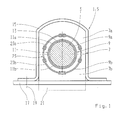
- Fig. 1 shows an elastomer bearing 1 with a stored therein, in section stabilizer 3 with a circular cross-section. This arrangement forms a bearing arrangement 5.
- the elastomer bearing 1 can generally be used for supporting rod-shaped bearing elements 3.
- the elastomeric bearing 1 has an elastomeric body 7.
- the elastomeric body 7 is divided in the embodiment in two halves 7a, 7b.
- the opening 7 penetrating the elastomer body 7 for receiving the stabilizer 3 represents the receiving area 9.
- the receiving area 9 is subdivided into two partial areas 9a, 9b in the exemplary embodiment, which are formed by two recesses in the elastomeric body 7 in the form of half-divided cylinders.
- the recesses are assigned to the elastomer body halves 7a, 7b.
- a tubular receiving element 11 is arranged on the inside of the circumference. This tubular receiving element 11 is also divided into two shell-shaped halves 11a, 11b, which in turn are associated with the subregions 9a and 9b.
- the receiving element 11 is connected by vulcanization with the elastomeric body 7.
- the stabilizer 3 is completely enclosed by the receiving element 11.
- the receiving element 11 consists of a metal material based on steel. It can also be formed of aluminum, plastic or a hybrid material.
- an adhesive 13 is arranged between the receiving element 11 and the stabilizer 3.
- the adhesive 13 is in the form of an adhesive layer 13, which substantially completely fills the space between the two joining partners stabilizer 3 and receiving element 11.
- the two joining partners are connected to each other substantially rotationally fixed.
- the elasticity of the adhesive layer 13 is negligible.
- Through the adhesive layer 13 a cohesive connection between the joining partners is made by their strength is ensured that the introduced via the stabilizer 3 and the receiving element 11 in the elastomer body 7 forces and moments are transmitted securely.
- the torsional movements of the stabilizer 3 while driving are absorbed by the elastomer of the elastomer body.
- the adhesive layer 13 is not shown to scale for illustrative purposes. The thickness of the adhesive layer 13 is actually in the tenth of a millimeter range or even lower.
- the adhesive 13 is formed as a pressure-sensitive adhesive 13 based on acrylate and is present in one layer without a carrier. It is likewise possible to use acrylate-based pressure-sensitive adhesives 13 which are multilayered without support or arranged on a support on both sides, it being possible for the two pressure-sensitive adhesives 13 in the latter case to have the same or different composition.
- the elastomer body enclosing the stabilizer 3 is in the in Fig. 1 shown installation state bordered by a ⁇ -shaped bracket 15 circumferentially.
- the bracket 15 is connected via through holes in the tabs of the bracket 15 with a vehicle body 17, which is only indicated schematically here. This is usually done by screw 19, which are also indicated here only schematically.
- the encapsulation of the elastomeric body 7 can also be effected by two substantially identical clamps, which embrace the elastomeric body 7 approximately in half. Such clamps are for example from the DE 10 2010 033 036 A1 known.
- the clamps or brackets 15 required for fastening the stabilizer 3 accommodated by the elastomeric body 7 preferably have beads extending in the circumferential direction, which, together with the form of corresponding recesses in the elastomeric body 7, counteract a wandering of the built-in stabilizer 3 in the vehicle transverse direction.
- the volume of the relaxed elastomer body 7 is therefore greater than the volume of the elastomeric body 7 in the installed state.
- the volume difference 21 between relaxed and installed state is indicated schematically.
- a tubular reinforcing element 23 is substantially completely embedded.
- the tubular reinforcing element 23 is divided into two shell-shaped halves 23a, 23b.
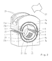
- FIG. 2 the elastomeric body 7 is shown in perspective. It can be seen that the receiving element 11 and the stiffening element 23 frontally slightly protruding from the elastomeric body 7. This has manufacturing reasons.
- the indicated adhesive layer 13 is protected in the delivery state of the elastomeric body 7 by a schematically shown, already withdrawn cover 27 made of a release material.
- bead-shaped recesses 29 extending in the vehicle longitudinal direction in the installed state, which are matched to the geometry of the bracket 15 in this area, can be seen.
- grooves 31 with a semicircular cross section are provided between the two aforementioned components on the left and right sides. These grooves 31 are required by the production and are in the in Fig. 1 illustrated biased state of the elastomeric body 7 closed by the bias again.
- the two-part construction of the elastomer body 7 shown in the exemplary embodiment with the components connected to it offers on the one hand the advantage that good accessibility for the application of the adhesive layer 13 is provided. On the other hand, the assembly with the stabilizer 3 is facilitated by the split structure.
Landscapes
- Engineering & Computer Science (AREA)
- Mechanical Engineering (AREA)
- General Engineering & Computer Science (AREA)
- Vibration Prevention Devices (AREA)
- Springs (AREA)
- Vehicle Body Suspensions (AREA)
- Support Of The Bearing (AREA)
Applications Claiming Priority (1)
| Application Number | Priority Date | Filing Date | Title |
|---|---|---|---|
| DE102012206453.2A DE102012206453B4 (de) | 2012-04-19 | 2012-04-19 | Elastomerlager zur Lagerung eines als Stabilisator ausgebildeten stabförmigen Lagerelements |
Publications (2)
| Publication Number | Publication Date |
|---|---|
| EP2653746A2 true EP2653746A2 (fr) | 2013-10-23 |
| EP2653746A3 EP2653746A3 (fr) | 2017-11-29 |
Family
ID=48044566
Family Applications (1)
| Application Number | Title | Priority Date | Filing Date |
|---|---|---|---|
| EP13160071.0A Withdrawn EP2653746A3 (fr) | 2012-04-19 | 2013-03-20 | Support en élastomère pour le stockage d'un élément de stockage en forme de tige conçu comme un stabilisateur |
Country Status (2)
| Country | Link |
|---|---|
| EP (1) | EP2653746A3 (fr) |
| DE (1) | DE102012206453B4 (fr) |
Cited By (1)
| Publication number | Priority date | Publication date | Assignee | Title |
|---|---|---|---|---|
| CN110891805A (zh) * | 2017-06-14 | 2020-03-17 | 蒂森克虏伯弹簧与稳定器有限责任公司 | 稳定器杆粘着支架、车辆稳定器杆和在车辆稳定器杆上形成稳定器杆粘着支架的方法 |
Families Citing this family (1)
| Publication number | Priority date | Publication date | Assignee | Title |
|---|---|---|---|---|
| DE102017108372A1 (de) | 2017-04-20 | 2018-07-12 | Schaeffler Technologies AG & Co. KG | Wankstabilisator für ein Kraftfahrzeug |
Citations (3)
| Publication number | Priority date | Publication date | Assignee | Title |
|---|---|---|---|---|
| DE10049611C2 (de) | 2000-10-05 | 2002-08-29 | Zf Lemfoerder Metallwaren Ag | Gummilager mit Versteifungselement |
| DE10231311B4 (de) | 2002-07-10 | 2004-09-30 | Vorwerk Autotec Gmbh & Co.Kg | Gummi-Lager |
| DE102010033036A1 (de) | 2010-08-02 | 2012-02-02 | Benteler Automobiltechnik Gmbh | Verfahren zur Herstellung eines Stabilisators mit Stabilisatorlager |
Family Cites Families (4)
| Publication number | Priority date | Publication date | Assignee | Title |
|---|---|---|---|---|
| GB9200905D0 (en) * | 1992-01-16 | 1992-03-11 | Tempered Spring Company The Li | Method of moulding a non-metallic component onto a metal bar |
| FR2766249A1 (fr) * | 1997-07-21 | 1999-01-22 | Caoutchouc Manuf Plastique | Palier elastique pour maintenir la barre de torsion d'un dispositif anti-devers |
| DE102004056884B4 (de) * | 2004-11-25 | 2007-11-22 | Vorwerk Autotec Gmbh & Co.Kg | Lager, insbesondere Gummi/Metall-Lager zur Anlenkung eines Stabilisators an einem Kraftfahrzeug |
| DE102010014257A1 (de) | 2010-04-08 | 2011-10-13 | Benteler Automobiltechnik Gmbh | Verfahren zur Verbindung eines Gummilagers oder eines Gummi-Metalllagers mit einer Lageraufnahme sowie Fahrwerkslager |
-
2012
- 2012-04-19 DE DE102012206453.2A patent/DE102012206453B4/de not_active Expired - Fee Related
-
2013
- 2013-03-20 EP EP13160071.0A patent/EP2653746A3/fr not_active Withdrawn
Patent Citations (3)
| Publication number | Priority date | Publication date | Assignee | Title |
|---|---|---|---|---|
| DE10049611C2 (de) | 2000-10-05 | 2002-08-29 | Zf Lemfoerder Metallwaren Ag | Gummilager mit Versteifungselement |
| DE10231311B4 (de) | 2002-07-10 | 2004-09-30 | Vorwerk Autotec Gmbh & Co.Kg | Gummi-Lager |
| DE102010033036A1 (de) | 2010-08-02 | 2012-02-02 | Benteler Automobiltechnik Gmbh | Verfahren zur Herstellung eines Stabilisators mit Stabilisatorlager |
Cited By (1)
| Publication number | Priority date | Publication date | Assignee | Title |
|---|---|---|---|---|
| CN110891805A (zh) * | 2017-06-14 | 2020-03-17 | 蒂森克虏伯弹簧与稳定器有限责任公司 | 稳定器杆粘着支架、车辆稳定器杆和在车辆稳定器杆上形成稳定器杆粘着支架的方法 |
Also Published As
| Publication number | Publication date |
|---|---|
| DE102012206453A1 (de) | 2013-10-24 |
| DE102012206453B4 (de) | 2019-02-28 |
| EP2653746A3 (fr) | 2017-11-29 |
Similar Documents
| Publication | Publication Date | Title |
|---|---|---|
| DE102011002065B4 (de) | Lageranordnung für eine Feder eines Fahrzeugfahrwerkes und Verfahren zur Bildung einer Lageranordnung | |
| DE19628651C2 (de) | Elastische Halterung mit zwei axial zusammengedrückten Elementen | |
| DE69617578T2 (de) | Vorrichtung zur Schwingungsisolation | |
| DE102008014695A1 (de) | Dichtungsbaugruppe eines Kugelgelenks sowie Kugelgelenk | |
| DE112006002536T5 (de) | Isolator | |
| DE102005058749A1 (de) | Fensterelement zum Einsetzen in einen Fensterausschnitt in einer Außenhaut eines Luftfahrzeugs | |
| DE102012013340B3 (de) | Scheibenbefestigung | |
| DE102019003884A1 (de) | Halterung für einen Fahrzeugstabilisator, Fahrzeugstabilisator und Verfahren | |
| DE10132379A1 (de) | Gummilager, vorzugsweise Stabilisatorlager, und Verfahren zur Montage des Lagers | |
| DE102016012538A1 (de) | Gummilager und Verfahren zum Herstellen eines Gummilagers | |
| DE102013002365B3 (de) | Faserverstärkte Versteifungsstrebe, Herstellverfahren und Kraftfahrzeugkarosserie | |
| DE102012206453B4 (de) | Elastomerlager zur Lagerung eines als Stabilisator ausgebildeten stabförmigen Lagerelements | |
| DE10226092A1 (de) | Elastisches Kopplungsbauteil, Anordnung mit zwei im Betrieb Schwingungen und/oder Vibrationen ausgesetzten Bauteilen und Träger zum Halten eines Bauteils an einem im Betrieb Schwingungen und/oder Vibrationen ausgesetzen Bauteil | |
| DE102016012731A1 (de) | Dämpfungskörper für eine obere Auflage | |
| WO2018219586A1 (fr) | Coussinet de palier | |
| DE102018131052A1 (de) | Verfahren zur Herstellung eines Bauteilverbunds und Kraftfahrzeug | |
| DE102022203022B4 (de) | Lageranordnung zur Verdrehsicherung eines Elastomerlagers | |
| DE19910308B4 (de) | Hydraulisch dämpfendes Gummilager mit Axialanschlägen sowie ein Verfahren zur Herstellung eines solchen hydraulisch dämpfenden Gummilagers mit integrierten Axialanschlägen | |
| DE102014221961A1 (de) | Nebenaggregat, insbesondere Scheibenwischeranlage, für ein Fahrzeug | |
| DE102017012168B4 (de) | Lageranordnung zur Verbindung zweier Bauteile | |
| DE102019206099B4 (de) | Vorrichtung zum Befestigen eines ersten Bauteils an einem zweiten Bauteil und zum Verpressen einer Dichtungsanordnung zwischen dem ersten Bauteil und einem dritten Bauteil | |
| DE102020208930B4 (de) | Brennstoffzellengehäuse, Brennstoffzelle und Verfahren zum Herstellen eines Brennstoffzellengehäuses | |
| DE102019200242B3 (de) | Halterung für eine Blattfeder und Verfahren zum Herstellen einer solchen Halterung | |
| DE102017127935B4 (de) | Blattfeder mit einem Federkörper aus einem Faserverbundwerkstoff und einer Mittenklemmung | |
| DE102017112841A1 (de) | Achskörper für ein Nutzfahrzeug und Herstellungsverfahren hierfür |
Legal Events
| Date | Code | Title | Description |
|---|---|---|---|
| PUAI | Public reference made under article 153(3) epc to a published international application that has entered the european phase |
Free format text: ORIGINAL CODE: 0009012 |
|
| AK | Designated contracting states |
Kind code of ref document: A2 Designated state(s): AL AT BE BG CH CY CZ DE DK EE ES FI FR GB GR HR HU IE IS IT LI LT LU LV MC MK MT NL NO PL PT RO RS SE SI SK SM TR |
|
| AX | Request for extension of the european patent |
Extension state: BA ME |
|
| PUAL | Search report despatched |
Free format text: ORIGINAL CODE: 0009013 |
|
| AK | Designated contracting states |
Kind code of ref document: A3 Designated state(s): AL AT BE BG CH CY CZ DE DK EE ES FI FR GB GR HR HU IE IS IT LI LT LU LV MC MK MT NL NO PL PT RO RS SE SI SK SM TR |
|
| AX | Request for extension of the european patent |
Extension state: BA ME |
|
| RIC1 | Information provided on ipc code assigned before grant |
Ipc: B60G 21/055 20060101ALI20171026BHEP Ipc: F16F 1/16 20060101AFI20171026BHEP |
|
| 17P | Request for examination filed |
Effective date: 20171120 |
|
| GRAJ | Information related to disapproval of communication of intention to grant by the applicant or resumption of examination proceedings by the epo deleted |
Free format text: ORIGINAL CODE: EPIDOSDIGR1 |
|
| GRAP | Despatch of communication of intention to grant a patent |
Free format text: ORIGINAL CODE: EPIDOSNIGR1 |
|
| INTG | Intention to grant announced |
Effective date: 20190211 |
|
| STAA | Information on the status of an ep patent application or granted ep patent |
Free format text: STATUS: THE APPLICATION IS DEEMED TO BE WITHDRAWN |
|
| 18D | Application deemed to be withdrawn |
Effective date: 20190622 |