EP2653767A1 - Verbindungsflansch - Google Patents
Verbindungsflansch Download PDFInfo
- Publication number
- EP2653767A1 EP2653767A1 EP12164503.0A EP12164503A EP2653767A1 EP 2653767 A1 EP2653767 A1 EP 2653767A1 EP 12164503 A EP12164503 A EP 12164503A EP 2653767 A1 EP2653767 A1 EP 2653767A1
- Authority
- EP
- European Patent Office
- Prior art keywords
- clamping piece
- joint flange
- parts
- expansion
- pipes
- Prior art date
- Legal status (The legal status is an assumption and is not a legal conclusion. Google has not performed a legal analysis and makes no representation as to the accuracy of the status listed.)
- Withdrawn
Links
- 230000000694 effects Effects 0.000 claims description 9
- 238000004064 recycling Methods 0.000 description 4
- 230000008602 contraction Effects 0.000 description 2
- 239000012530 fluid Substances 0.000 description 2
- 238000000034 method Methods 0.000 description 2
- 230000005540 biological transmission Effects 0.000 description 1
- 239000007789 gas Substances 0.000 description 1
- 239000007788 liquid Substances 0.000 description 1
- 238000012986 modification Methods 0.000 description 1
- 230000004048 modification Effects 0.000 description 1
Images


Classifications
-
- F—MECHANICAL ENGINEERING; LIGHTING; HEATING; WEAPONS; BLASTING
- F16—ENGINEERING ELEMENTS AND UNITS; GENERAL MEASURES FOR PRODUCING AND MAINTAINING EFFECTIVE FUNCTIONING OF MACHINES OR INSTALLATIONS; THERMAL INSULATION IN GENERAL
- F16L—PIPES; JOINTS OR FITTINGS FOR PIPES; SUPPORTS FOR PIPES, CABLES OR PROTECTIVE TUBING; MEANS FOR THERMAL INSULATION IN GENERAL
- F16L51/00—Expansion-compensation arrangements for pipe-lines
- F16L51/02—Expansion-compensation arrangements for pipe-lines making use of a bellows or an expansible folded or corrugated tube
- F16L51/022—Expansion-compensation arrangements for pipe-lines making use of a bellows or an expansible folded or corrugated tube with a single corrugation
-
- F—MECHANICAL ENGINEERING; LIGHTING; HEATING; WEAPONS; BLASTING
- F16—ENGINEERING ELEMENTS AND UNITS; GENERAL MEASURES FOR PRODUCING AND MAINTAINING EFFECTIVE FUNCTIONING OF MACHINES OR INSTALLATIONS; THERMAL INSULATION IN GENERAL
- F16L—PIPES; JOINTS OR FITTINGS FOR PIPES; SUPPORTS FOR PIPES, CABLES OR PROTECTIVE TUBING; MEANS FOR THERMAL INSULATION IN GENERAL
- F16L23/00—Flanged joints
- F16L23/02—Flanged joints the flanges being connected by members tensioned axially
- F16L23/032—Flanged joints the flanges being connected by members tensioned axially characterised by the shape or composition of the flanges
Definitions
- the present invention relates to a joint flange A, and more particularly to a joint flange A which provides for combining an expansion fitting 2 with pipes 3, so that the expansion fitting 2 can be subjected to a uniform force after combining, in order to prevent the expansion fitting 2 from damage by being subjected to too large a force and to allow a leak-proof effect to an expansion connector to be more rigorous, thereby enabling the joint flange A to be assembled and dismembered more conveniently.
- a pipe is to provide a path of transmission for all kinds of fluids, including liquids and gases. All kinds of expansion connectors in the pipes are used primarily to absorb expansion or contraction resulted from a change of temperature, avoiding damage by the expansion or contraction and reducing leakage of the fluids in the pipes.
- FIG. 1 it shows a conventional expansion connector having an annular joint flange 1. A surface of the joint flange 1 is provided with plural fixing holes 11 that are spaced apart. After the joint flange 1 has been sheathed on a contracted rim of an expansion fitting 2, pipes 3 with fixing holes 31 are put at openings of the expansion fitting 2 and then the fixing holes 31, 11 are locked by screws 4.
- This conventional expansion connector is provided with following shortcomings upon assembling:
- the present invention discloses a leak-proof structure of an expansion connector, such that the expansion connector can be assembled more conveniently and can be easily dismembered for recycling.
- the primary object of the present invention is to provide a joint flange, allowing an expansion fitting to be subjected to a uniform force after the expansion fitting has been joined with the joint flange, in order to prevent the expansion fitting from damage by being subjected to too large a force and to enable a leak-proof effect to an expansion connector to be more rigorous, thereby allowing the joint flange to be assembled and dismembered more conveniently to facilitate dismembering and recycling the joint flange for environment protection.
- the abovementioned joint flange is assembled by a first clamping piece and a second clamping piece.
- the first clamping piece and the second clamping piece are roughly in a C-shape to form clamp opening at a center of inner rim of the clamping pieces.
- a periphery of the first clamping piece and the second clamping piece is provided with a protruding wall that is extended upward vertically with a proper height; whereas, two ends of the first clamping piece and the second clamping piece are provided respectively with latching parts and positioning parts.
- a surface of the first clamping piece and the second clamping piece is provided with plural fixing holes that are spaced apart.
- the first clamping piece and the second clamping piece are clamped opposite to each other in a contracted rim of an expansion fitting and are locked with pipes from the fixing holes by joining the latching parts with the positioning parts. Furthermore, limitation is constituted by the protruding walls, allowing the expansion fitting to be subjected to a uniform force, so that the expansion fitting can be prevented from damage by being subjected to too large a force and a leak-proof effect to an expansion connector can be more rigorous, thereby allowing the joint flange to be assembled and dismembered more conveniently.
- two ends of the latching parts and the positioning parts of the first clamping piece and the second clamping piece are provided respectively with corresponding stage parts to constitute positioning by latching the stage parts with respect to each other.
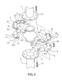
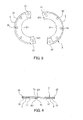
- FIG. 2 and FIG. 3 it shows a three-dimensional exploded view of the present invention and a plan view of clamping pieces of the present invention.
- the present invention discloses a joint flange A that is assembled by a first clamping piece 5 and a second clamping piece 6.
- the first clamping piece 5 and the second clamping piece 6 are roughly in a C-shape to form clamp openings 51, 61 at a center of inner rim of the first and second clamping piece 5, 6.
- a periphery of the first clamping piece 5 and the second clamping piece 6 is provided with a protruding wall 52, 62 that is extended upward vertically with a proper height.
- An end of the first clamping piece 5 and the second clamping piece 6 is provided with a latching part 53, 63 constituted by a stage part 531, 631; whereas, the other end is provided with a positioning part 54, 64 constituted by a stage part 541, 641.
- a surface of the first clamping piece 5 and the second clamping piece 6 is provided with plural fixing holes 55, 65 that are spaced apart.
- the joint flange A is formed, such that when using the joint flange A, the first clamping piece 5 and the second clamping piece 6 are clamped opposite to each other in a contracted rim of an expansion fitting 2 and by joining the latching parts 53, 63 with the positioning parts 54, 64, pipes 3 are put above and below the expansion fitting 2, followed by using screws 4 to penetrate from fixing holes 31 of the pipes 3 as well as the fixing holes 55, 65 of the first clamping piece 5 and the second clamping piece 6 to lock the first clamping piece 5 and the second clamping piece 6 with the pipes 3.
- limitation to the expansion fitting 2 is formed by the protruding walls 52, 62, so that the expansion fitting 2 can be subjected to a uniform force, thereby preventing the expansion fitting 2 from damage by being subjected to too large a force and allowing a leak-proof effect to an expansion connector to be more rigorous, which further facilitates assembling and dismembering the joint flange A.
- FIG. 4 it shows a schematic view of an implementation of joining the clamping pieces, according to the present invention.
- the first clamping piece 5 and the second clamping piece 6 are clamped opposite to each other in the contracted rim of the expansion fitting 2, and after the first clamping piece 5 and the second clamping piece 6 have been clamped, as the latching part 53 (63) and the positioning part 54 (64) at the ends are corresponding to the stage parts 531 (631), 541 (641), the stage parts 531 (631), 541 (641) can be overlapped with respect to each other to join the first clamping piece 5 with the second clamping piece 6, without requiring the flange to pass through the openings of the expansion fitting 2, like a conventional flange. Therefore, the assembling work is rather convenient and fast; in addition, when the expansion fitting 2 is damaged, the first clamping piece 5 can be separated with the second clamping piece 6 by just releasing the screws 4 to facilitate recycling the expansion fitting 2.
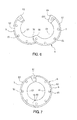
- FIG. 5 it shows a cutaway view of the present invention after being assembled.
- the first clamping piece 5 and the second clamping piece 6 are clamped opposite to each other in the contracted rim of the expansion fitting 2 and are joined by overlapping the corresponding stage parts, so as to constitute the joint flange A.
- the protruding walls 52, 62 at the peripheries are able to abut at bottom surfaces of the pipes 3 to form the function of limitation, such that the expansion fitting 2 can be subjected to a uniform force, thereby preventing the expansion fitting 2 from damage due to too large a force to be subjected and allowing the leak-proof effect to the expansion connector to be more rigorous.
- a second embodiment of the present invention includes a joint flange A that is formed by a first clamping piece 5 and a second clamping piece 6.
- the first clamping piece 5 and the second clamping piece 6 are roughly in a C-shape to form clamp openings 51, 61 at a center of inner rim of the first and second clamping piece 5, 6.
- a periphery of the first clamping piece 5 and the second clamping piece 6 is provided with a protruding wall 52, 62 that is extended upward vertically with a proper height.
- first clamping piece 5 and the second clamping piece 6 An end of the first clamping piece 5 and the second clamping piece 6 is provided respectively with a latching part 53 having a stage part 531 (not shown in the drawings, please refer to FIG. 2 ) and a positioning part 64 having a stage part 641.
- a surface of the first clamping piece 5 and the second clamping piece 6 is provided with plural fixing holes 55, 65 that are spaced apart; whereas, the other end of the first clamping piece 5 and the second clamping piece 6 is provided respectively with a pivot part 56, 66.
- the first clamping piece 5 and the second clamping piece 6 are opened and clamped opposite to each other in a contracted rim of an expansion fitting, so as to form a different type of assembling method to the joint flange A by joining the latching part 53 with the positioning part 64.
- the joint flange is formed by the clamping pieces having the latching parts and the positioning parts, along with the protruding walls at the peripheries of the clamping pieces.
- the present invention enables the expansion fitting to be subjected to a uniform force after the expansion fitting has been combined with the joint flange, so that the expansion fitting can be prevented from damage by being subjected to too large a force and the leak-proof effect to the expansion connector can be more rigorous, which allows the joint flange to be assembled and dismembered more conveniently and facilitates dismembering the joint flange for recycling to protect the environment.
Landscapes
- Engineering & Computer Science (AREA)
- General Engineering & Computer Science (AREA)
- Mechanical Engineering (AREA)
- Flanged Joints, Insulating Joints, And Other Joints (AREA)
Priority Applications (1)
| Application Number | Priority Date | Filing Date | Title |
|---|---|---|---|
| EP12164503.0A EP2653767A1 (de) | 2012-04-17 | 2012-04-17 | Verbindungsflansch |
Applications Claiming Priority (1)
| Application Number | Priority Date | Filing Date | Title |
|---|---|---|---|
| EP12164503.0A EP2653767A1 (de) | 2012-04-17 | 2012-04-17 | Verbindungsflansch |
Publications (1)
| Publication Number | Publication Date |
|---|---|
| EP2653767A1 true EP2653767A1 (de) | 2013-10-23 |
Family
ID=45976807
Family Applications (1)
| Application Number | Title | Priority Date | Filing Date |
|---|---|---|---|
| EP12164503.0A Withdrawn EP2653767A1 (de) | 2012-04-17 | 2012-04-17 | Verbindungsflansch |
Country Status (1)
| Country | Link |
|---|---|
| EP (1) | EP2653767A1 (de) |
Cited By (1)
| Publication number | Priority date | Publication date | Assignee | Title |
|---|---|---|---|---|
| CN108591647A (zh) * | 2018-04-25 | 2018-09-28 | 连云港格航工业设计有限公司 | 一种可拆卸型石英连接法兰 |
Citations (4)
| Publication number | Priority date | Publication date | Assignee | Title |
|---|---|---|---|---|
| US3761114A (en) * | 1971-08-30 | 1973-09-25 | Victaulic Co Ltd | Pipe to flange couplings |
| DE4108894A1 (de) * | 1991-03-19 | 1992-09-24 | Doering Ernst Werner Dipl Ing | Losflanschverbindung zum direkten oder nachtraeglichen einbau bei vorhandenen bundbuchsen im rohrleitungs-, behaelter- und apparatebau aus kunststoffen |
| US6264251B1 (en) * | 1999-10-15 | 2001-07-24 | Victaulic Company Of America | Segmented flange coupler for grooved pipe |
| EP1512899A1 (de) * | 2003-09-05 | 2005-03-09 | SANKEI GIKEN Co., Ltd. | Flansch |
-
2012
- 2012-04-17 EP EP12164503.0A patent/EP2653767A1/de not_active Withdrawn
Patent Citations (4)
| Publication number | Priority date | Publication date | Assignee | Title |
|---|---|---|---|---|
| US3761114A (en) * | 1971-08-30 | 1973-09-25 | Victaulic Co Ltd | Pipe to flange couplings |
| DE4108894A1 (de) * | 1991-03-19 | 1992-09-24 | Doering Ernst Werner Dipl Ing | Losflanschverbindung zum direkten oder nachtraeglichen einbau bei vorhandenen bundbuchsen im rohrleitungs-, behaelter- und apparatebau aus kunststoffen |
| US6264251B1 (en) * | 1999-10-15 | 2001-07-24 | Victaulic Company Of America | Segmented flange coupler for grooved pipe |
| EP1512899A1 (de) * | 2003-09-05 | 2005-03-09 | SANKEI GIKEN Co., Ltd. | Flansch |
Cited By (1)
| Publication number | Priority date | Publication date | Assignee | Title |
|---|---|---|---|---|
| CN108591647A (zh) * | 2018-04-25 | 2018-09-28 | 连云港格航工业设计有限公司 | 一种可拆卸型石英连接法兰 |
Similar Documents
| Publication | Publication Date | Title |
|---|---|---|
| JP5379120B2 (ja) | 導管連結器具 | |
| US20130270818A1 (en) | Joint flange | |
| US10583519B2 (en) | Friction stir welding method and assembly | |
| JP7061608B2 (ja) | フランジ継手の平型ガスケット用の取付装置 | |
| KR20150001595U (ko) | 파이프용 클램프 | |
| CN204254027U (zh) | 管道锁紧辅助治具及管道锁紧装置 | |
| EP2653767A1 (de) | Verbindungsflansch | |
| US20160050904A1 (en) | Utility conduit cover | |
| KR101821229B1 (ko) | 배관 피팅용 고정 장치 | |
| US11143239B2 (en) | Chain slider | |
| US20160161034A1 (en) | Modular pipe clamp | |
| CN104746984A (zh) | 滑移式铰链 | |
| US20190170287A1 (en) | Joint assembly for fluid carrying pipes | |
| CN206221852U (zh) | 一种可拆卸的法兰接头及管道对接装置 | |
| US1470485A (en) | Coupling clamp | |
| US10788153B2 (en) | Joint assembly for fluid carrying pipes | |
| KR200422136Y1 (ko) | 가스 흡 배출관의 연결 클램프 | |
| JP3208106U (ja) | ハウジング型管継手 | |
| CN105305327A (zh) | 一种低气压电缆密封装置及其制造方法 | |
| KR101895828B1 (ko) | 유로 연결을 위한 이지-실 개스킷 | |
| KR101776780B1 (ko) | 원터치 철근 커플러 조립방법 | |
| CN206512471U (zh) | 洗衣机 | |
| US9541222B2 (en) | Duct fittings | |
| CN202484288U (zh) | 深海耐压圆口法兰对接锁死解脱装置 | |
| CN207961840U (zh) | 管道接头 |
Legal Events
| Date | Code | Title | Description |
|---|---|---|---|
| PUAI | Public reference made under article 153(3) epc to a published international application that has entered the european phase |
Free format text: ORIGINAL CODE: 0009012 |
|
| 17P | Request for examination filed |
Effective date: 20120516 |
|
| AK | Designated contracting states |
Kind code of ref document: A1 Designated state(s): AL AT BE BG CH CY CZ DE DK EE ES FI FR GB GR HR HU IE IS IT LI LT LU LV MC MK MT NL NO PL PT RO RS SE SI SK SM TR |
|
| AX | Request for extension of the european patent |
Extension state: BA ME |
|
| STAA | Information on the status of an ep patent application or granted ep patent |
Free format text: STATUS: THE APPLICATION IS DEEMED TO BE WITHDRAWN |
|
| 18D | Application deemed to be withdrawn |
Effective date: 20140424 |