EP2653790A2 - Device for mounting a tube in a groove of a thermal conduction profile - Google Patents
Device for mounting a tube in a groove of a thermal conduction profile Download PDFInfo
- Publication number
- EP2653790A2 EP2653790A2 EP13001976.3A EP13001976A EP2653790A2 EP 2653790 A2 EP2653790 A2 EP 2653790A2 EP 13001976 A EP13001976 A EP 13001976A EP 2653790 A2 EP2653790 A2 EP 2653790A2
- Authority
- EP
- European Patent Office
- Prior art keywords
- groove
- wärmeleitprofil
- tube
- profile
- rollers
- Prior art date
- Legal status (The legal status is an assumption and is not a legal conclusion. Google has not performed a legal analysis and makes no representation as to the accuracy of the status listed.)
- Granted
Links
Images

Classifications
-
- F—MECHANICAL ENGINEERING; LIGHTING; HEATING; WEAPONS; BLASTING
- F24—HEATING; RANGES; VENTILATING
- F24D—DOMESTIC- OR SPACE-HEATING SYSTEMS, e.g. CENTRAL HEATING SYSTEMS; DOMESTIC HOT-WATER SUPPLY SYSTEMS; ELEMENTS OR COMPONENTS THEREFOR
- F24D3/00—Hot-water central heating systems
- F24D3/12—Tube and panel arrangements for ceiling, wall, or underfloor heating
- F24D3/14—Tube and panel arrangements for ceiling, wall, or underfloor heating incorporated in a ceiling, wall or floor
- F24D3/149—Tube-laying devices
-
- B—PERFORMING OPERATIONS; TRANSPORTING
- B25—HAND TOOLS; PORTABLE POWER-DRIVEN TOOLS; MANIPULATORS
- B25B—TOOLS OR BENCH DEVICES NOT OTHERWISE PROVIDED FOR, FOR FASTENING, CONNECTING, DISENGAGING, OR HOLDING
- B25B27/00—Hand tools, specially adapted for fitting together or separating parts or objects whether or not involving some deformation, not otherwise provided for
- B25B27/0092—Tools moving along strips, e.g. decorating or sealing strips, to insert them in, or remove them from, grooves or profiles
-
- B—PERFORMING OPERATIONS; TRANSPORTING
- B65—CONVEYING; PACKING; STORING; HANDLING THIN OR FILAMENTARY MATERIAL
- B65H—HANDLING THIN OR FILAMENTARY MATERIAL, e.g. SHEETS, WEBS, CABLES
- B65H51/00—Forwarding filamentary material
- B65H51/02—Rotary devices, e.g. with helical forwarding surfaces
- B65H51/04—Rollers, pulleys, capstans, or intermeshing rotary elements
- B65H51/08—Rollers, pulleys, capstans, or intermeshing rotary elements arranged to operate in groups or in co-operation with other elements
- B65H51/10—Rollers, pulleys, capstans, or intermeshing rotary elements arranged to operate in groups or in co-operation with other elements with opposed coacting surfaces, e.g. providing nips
-
- F—MECHANICAL ENGINEERING; LIGHTING; HEATING; WEAPONS; BLASTING
- F24—HEATING; RANGES; VENTILATING
- F24D—DOMESTIC- OR SPACE-HEATING SYSTEMS, e.g. CENTRAL HEATING SYSTEMS; DOMESTIC HOT-WATER SUPPLY SYSTEMS; ELEMENTS OR COMPONENTS THEREFOR
- F24D3/00—Hot-water central heating systems
- F24D3/12—Tube and panel arrangements for ceiling, wall, or underfloor heating
- F24D3/14—Tube and panel arrangements for ceiling, wall, or underfloor heating incorporated in a ceiling, wall or floor
- F24D3/148—Tube and panel arrangements for ceiling, wall, or underfloor heating incorporated in a ceiling, wall or floor with heat spreading plates
-
- B—PERFORMING OPERATIONS; TRANSPORTING
- B65—CONVEYING; PACKING; STORING; HANDLING THIN OR FILAMENTARY MATERIAL
- B65H—HANDLING THIN OR FILAMENTARY MATERIAL, e.g. SHEETS, WEBS, CABLES
- B65H2701/00—Handled material; Storage means
- B65H2701/30—Handled filamentary material
- B65H2701/33—Hollow or hose-like material
-
- Y—GENERAL TAGGING OF NEW TECHNOLOGICAL DEVELOPMENTS; GENERAL TAGGING OF CROSS-SECTIONAL TECHNOLOGIES SPANNING OVER SEVERAL SECTIONS OF THE IPC; TECHNICAL SUBJECTS COVERED BY FORMER USPC CROSS-REFERENCE ART COLLECTIONS [XRACs] AND DIGESTS
- Y02—TECHNOLOGIES OR APPLICATIONS FOR MITIGATION OR ADAPTATION AGAINST CLIMATE CHANGE
- Y02B—CLIMATE CHANGE MITIGATION TECHNOLOGIES RELATED TO BUILDINGS, e.g. HOUSING, HOUSE APPLIANCES OR RELATED END-USER APPLICATIONS
- Y02B30/00—Energy efficient heating, ventilation or air conditioning [HVAC]
Definitions
- the invention relates to a device for mounting a pipe in a groove of a planteoprofils.
- the device according to the invention is particularly applicable to politicians, which are part of a ceiling or a wall and are clad in the finished state with plasterboard.
- a device according to the invention is used when kilometersleitprofile are already mounted on a ceiling or wall and must be provided with pipes before they are covered with plasterboard.
- the object underlying the invention is to provide a device by means of which the assembly of a pipe in a groove of a already mounted on a wall or ceiling of a building shallleitprofils is simplified.
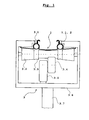
- the mounting device 3 knows each groove 1.1 of theticianleitprofils 1 in which a pipe 2 is clamped, at least three rollers 3.1, 3.2 3.3, whose rolling direction is aligned parallel to the profile direction of the sauitprofils 1.
- the two rollers 3.1, 3.2 are arranged at an axial distance from each other and press with their lateral surfaces with respect to the plane of the opening of the groove 1.1 from different sides to the heat transfer 1.
- the longitudinal section of a groove 1.1 located in the vicinity of this pair of rollers is widened so that its opening area there is at least approximately as wide as the diameter of the tube 2 if this is not deformed.
- the lateral surface of the third roller 3.3 is designed waisted and it protrudes at the opening surface of the groove 1.1.
- the tube 2 extends at the side facing the groove 1.1 side of the lateral surface of the roller 3.3.
- rollers 3.2 and 3.3 are arranged on a common axis, combined to form a common reel body and driven by a motor.
- the drive includes a motor 3.5 and a driven by this friction wheel 3.4 which rests with its peripheral surface on said roller body.
- Drive and rollers are held in an approximately C-shaped housing 3.6, which in turn is held on a stem 3.7, through which passes the power supply for the drive.
- the handle 3.7 the device be held and guided by a human and attached to an already on the ceiling of a room suspended heat conduction 1.
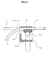
- the device 13 moves from Fig. 2 according to Fig. 2 from right to left.
- the device 13 is opposite to that of Fig. 1 supplemented by additional roles.
- roller 3.7 Just behind the roller 3.3, which introduces the tube 2 in the groove on the heat conduction and which presses with the roller 3.2 from below to the bathleitprofil, runs another roller 3.7, which also has a waisted lateral surface.
- the roller 3.7 presses on such a longitudinal region from the side of the slot opening of the shallleitprofils forth to the there located in the groove tube 2, at which the opening width of the groove on the heat conduction against the maximum expanded state is already slightly narrowed. The roller 3.7 thus ensures that the tube 2 is completely inserted into the groove.
- a set of rollers 3.8 is arranged with respect to the direction of movement of the device 13 on the furnishedleitprofil 1 in front of the roller 3.3, through which the tube 2 is introduced into the groove on the réelleleitprofil.
- the axes of rotation do not have to be parallel to the already discussed roles, a not yet clamped in the groove on the heat conduction longitudinal region of the clamped pipe 2 is directed him optimizing location and direction for further processing.
- the device according to the invention is particularly applicable to plantetprofilen, which are designed so that the serving for receiving in each case a tube grooves are particularly easy elastically expandable to bring the tube.
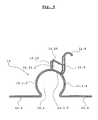
- Fig. 4 shows a section of a primafils 13 which is well produced by extrusion of aluminum. It has two respectively two-layer wall portions 11.3, 11.13, which is determined by the groove 11.1 which is intended for receiving a tube, project, and divide the boundary of the groove 11.1 in three surface areas 11.1.1, 11.1.2, 11.1.3, by the narrow gap between the two layers of a wall portion 11.3, 11.13 opens into the groove 11.1.
- a division of the Nutbegrenzung in only two sub-areas is the division of the Nutbegrenzung in three sub-areas, the opening of the groove 11.1 on and softer elastically expandable.
- the neutron-senor filament 13 has a profile wall 11.23, which protrudes from the wall portion 11.3 and just above the free end of the wall portion 11.13 protrudes.
- the profile wall 11.23 is connected only via a very thin web, so that the profile wall 11.23 against the wall portion 11.13 by plastic deformation of the thin web is pivotable without much effort.
- the profile wall 11.23 is pivoted downwards around the narrow connecting web to the wall region 11.3 so that its free end strikes the free end of the wall region 11.13 , while the wall portion 11.13 bends slightly away from the wall portion 11.3 away and finally locked at an angle range 11.13.1 of the wall portion.
- the process of pivoting the profile wall 11.23 can be achieved by another role of a device according to the invention, which is behind the rollers, which cause the insertion of the tube and presses from above on the profile wall 11.23.
- Fig. 5 shows a section of another rectifierfils 21 which is well produced by extrusion of aluminum and on which devices of the invention are well applicable. Also, this heat conduction profile has two two-layer wall portions 21.3, 21.13 through which the boundary surface of the groove 21.1 in which a pipe is clamped is divided into three sub-areas.
- the skilletleitprofil has two profile walls 21.23, which from the outside of the central boundary surface of the groove 21.1 in the vicinity of each of a two-layered Wall area 21.3, 21.13 protrude.
- the two wall regions 21.23 are bent by mechanical action about their junction with the boundary surface of the groove 21.1 so that they abut with their free end against the respective wall region 21.3, 21.13, deflecting them slightly and thereby engage the wall area 21.3 or 21.13.
- this results in a better contact between the tube and the boundary surfaces of the groove.
- the bending of the wall portions 21.23 can also be done by a device according to the invention.
- the rollers 3.1 would have to be made so narrow that they would fit between the foot points of the profile walls 21.23 on the outside of the boundary surface of the groove 21.1.
- the direction of movement of the device behind the rollers 3.1 is at about the same height and with the axes of the rollers 3.1 parallel axis alignment another role to install.
- the profile walls 21.23 must be bent in the manner discussed.
- this additional role must be so long that it rests against one of the foot points of the profile walls 21.23 remote wall portion of this profile walls and pushes down there.
- a roller which causes the widening of the opening of the groove relative to that role with waisted lateral surface, through which a tube is inserted into a groove of the varnishleitprofils, with respect to the direction of travel of the device at the bathleitprofil be slightly further forward , This facilitates the introduction of the tube into the groove.
- an additional set of rollers may be provided, which is arranged on the device behind the previously discussed sets of rollers and serves to any unwanted plastic deformation of the shallleitprofils and / or of the tube through the front Roll set were caused to undo again.
Landscapes
- Engineering & Computer Science (AREA)
- Mechanical Engineering (AREA)
- General Engineering & Computer Science (AREA)
- Chemical & Material Sciences (AREA)
- Combustion & Propulsion (AREA)
- Thermal Sciences (AREA)
- Physics & Mathematics (AREA)
- Steam Or Hot-Water Central Heating Systems (AREA)
- Conveying And Assembling Of Building Elements In Situ (AREA)
- Thermotherapy And Cooling Therapy Devices (AREA)
- Resistance Heating (AREA)
- Orthopedics, Nursing, And Contraception (AREA)
- Heat Treatment Of Articles (AREA)
- Supports For Pipes And Cables (AREA)
Abstract
Description
Die Erfindung betrifft eine Vorrichtung für die Montage eines Rohres in einer Nut eines Wärmeleitprofils.The invention relates to a device for mounting a pipe in a groove of a Wärmeleitprofils.
Die erfindungsgemäße Vorrichtung ist vor allem an Wärmeleitprofilen anwendbar, welche Teil einer Decke oder eine Wand sind und in fertigem Zustand mit Gipskartonplatten verkleidet sind. Im normalen Einsatzfall kommt eine erfindungsgemäße Vorrichtung dann zum Einsatz, wenn Wärmeleitprofile schon an einer Decke oder Wand montiert sind und mit Rohren versehen werden müssen, bevor sie mit Gipskartonplatten verkleidet werden.The device according to the invention is particularly applicable to Wärmeleitprofilen, which are part of a ceiling or a wall and are clad in the finished state with plasterboard. In normal use, a device according to the invention is used when Wärmeleitprofile are already mounted on a ceiling or wall and must be provided with pipes before they are covered with plasterboard.
Die Schriften
Die der Erfindung zu Grunde liegende Aufgabe besteht darin, eine Vorrichtung zu schaffen, mit Hilfe derer die Montage eines Rohres in einer Nut eines schon an einer Wand oder Decke eines Gebäudes montierten Wärmeleitprofils vereinfacht wird.The object underlying the invention is to provide a device by means of which the assembly of a pipe in a groove of a already mounted on a wall or ceiling of a building Wärmeleitprofils is simplified.
Für das Lösen der Aufgaben wird vorgeschlagen
- die Vorrichtung mit einem zwei gegenüberliegende offene Flächen aufweisenden Gehäuse und diesem gegenüber drehbaren Rollen auszustatten, wobei
- das Wärmeleitprofil durch das Gehäuse durchführbar ist und die Vorrichtung gegenüber dem Wärmeleitprofil entlang dessen Profilrichtung fortbewegbar ist, wobei
- die Rollrichtung der Rollen parallel zur Profilrichtung des Wärmeleitprofils ausgerichtet ist, wobei
- mindestens zwei Rollen an voneinander beabstandeten Querschnittsflächenbereichen des Wärmeleitprofils an dem Wärmeleitprofil unter Druck anliegen und eine Biegekraft um zur Profilrichtung parallel liegende Biegeachsen auf das Wärmeleitprofil ausüben durch welche die Öffnung einer als für die Aufnahme eines Rohres vorgesehenen Nut erweitert wird, wobei
- die Vorrichtung eine weitere Rolle aufweist, welche eine taillierte Mantelfläche hat, mit dieser an die Öffnungsfläche der für die Aufnahme eines Rohres vorgesehenen Nut am Wärmeleitprofil heranragt und wobei
- an der der Nut zugewandten Seite der letzteren Rolle das in die Nut einzubringende Rohr anliegt.
- to equip the device with a two opposing open surfaces having housing and this opposite rotatable rollers, wherein
- the Wärmeleitprofil is feasible through the housing and the device relative to the Wärmeleitprofil along the profile direction is wegbewegbar, wherein
- the rolling direction of the rollers is aligned parallel to the profile direction of the Wärmeleitprofils, wherein
- at least two rollers abut against each other at spaced-apart cross-sectional surface areas of the Wärmeleitprofils on the Wärmeleitprofil under pressure and exert a bending force to the profile direction lying parallel bending axes on the Wärmeleitprofil by which the opening of a designated as a receiving a pipe groove is widened
- the device has a further role, which has a waisted lateral surface, with this on the opening surface of the intended for receiving a pipe groove on the heat conduction and protrudes
- on the side facing the groove of the latter roll, the tube to be introduced into the groove rests.
Die Erfindung wird an Hand von Zeichnungen veranschaulicht.
- Fig. 1:
- zeigt in Teilschnittansicht eine Prinzipskizze einer ersten erfindungsgemäßen Montagevorrichtung im Einsatz. Die Blickrichtung liegt dabei parallel zur Profilrichtung des Wärmeleitprofils.
- Fig. 2:
- zeigt in Teilschnittansicht eine Prinzipskizze einer zweiten erfindungsgemäßen Montagevorrichtung im Einsatz. Die Blickrichtung liegt horizontal, normal zur Profilrichtung des Wärmeleitprofils.
- Fig. 3:
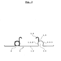
- zeigt in Profilansicht das Wärmeleitprofil von
Fig. 1 einschließlich einem darin eingeklemmten Rohr. - Fig. 4:
- zeigt in Profilansicht einen Ausschnitt eines zweiten Wärmeleitprofils an welchem eine erfindungsgemäße Vorrichtung auch gut anwendbar ist.
- Fig. 1:
- shows a partial sectional view of a schematic diagram of a first inventive mounting device in use. The viewing direction is parallel to the profile direction of the Wärmeleitprofils.
- Fig. 2:
- shows a partial sectional view of a schematic diagram of a second mounting device according to the invention in use. The viewing direction is horizontal, normal to the profile direction of the Wärmeleitprofils.
- 3:
- shows in profile view the heat conduction profile of
Fig. 1 including a clamped pipe. - 4:
- shows in profile view a section of a second Wärmeleitprofils on which a device according to the invention is also well applicable.
Die Montagevorrichtung 3 gemäß
Die beiden Rollen 3.1, 3.2 sind in einem Axialabstand zueinander angeordnet und drücken mit ihren Mantelflächen bezüglich der Ebene der Öffnung der Nut 1.1 von unterschiedlichen Seiten her an das Wärmeleitprofil 1 an. Dadurch wird der im Nahbereich dieses Rollenpaares befindliche Längsabschnitt einer Nut 1.1 aufgeweitet, sodass ihre Öffnungsfläche dort zumindest annähernd so breit wird wie der Durchmesser des Rohres 2 wenn dieses nicht verformt ist.The two rollers 3.1, 3.2 are arranged at an axial distance from each other and press with their lateral surfaces with respect to the plane of the opening of the groove 1.1 from different sides to the
Die Mantelfläche der dritten Rolle 3.3 ist tailliert ausgeführt und sie ragt an die Öffnungsfläche der Nut 1.1. Das Rohr 2 verläuft an der der Nut 1.1 zugewandten Seite der Mantelfläche der Rolle 3.3.The lateral surface of the third roller 3.3 is designed waisted and it protrudes at the opening surface of the groove 1.1. The
Indem die ganze Montagevorrichtung 3 in Profilrichtung des Wärmeleitprofils 1 bewegt wird, drückt die Rolle 3.3 den an ihr befindlichen Längsbereich des Rohrs 2 in die Nut 1.1, deren Flanken an diesem Längsbereich durch die Rollen 3.1, 3.2 gegenüber dem unverformten Zustand elastisch aufgeweitet sind.By the
In dem in
Bestimmungsgemäß bewegt sich die erfindungsgemäße Vorrichtung 13 von
An der Oberseite des Wärmeleitprofils rollt eine ganze Reihe von hintereinander angeordneten Rollen 3.1.At the top of the Wärmeleitprofils rolls a whole series of successively arranged rollers 3.1.
Genau hinter der Rolle 3.3, welche das Rohr 2 in die Nut am Wärmeleitprofil einführt und welche mit der Rolle 3.2 die von unten her an das Wärmeleitprofil andrückt, läuft eine weitere Rolle 3.7, welche ebenfalls eine taillierte Mantelfläche aufweist. Die Rolle 3.7 drückt an einem solchen Längsbereich von der Seite der Nutöffnung des Wärmeleitprofils her an das dort in der Nut befindliche Rohr 2, an welchem die Öffnungsbreite der Nut am Wärmeleitprofil gegenüber dem maximal aufgeweiteten Zustand schon wieder etwas verengt ist. Die Rolle 3.7 stellt damit sicher, dass das Rohr 2 ganz in die Nut eingebracht wird.Just behind the roller 3.3, which introduces the
Ein Satz von Rollen 3.8 ist bezüglich der Bewegungsrichtung der Vorrichtung 13 am Wärmeleitprofil 1 vor der Rolle 3.3 angeordnet, durch welche das Rohr 2 in die Nut am Wärmeleitprofil eingebracht wird. An den Mantelflächen dieser zusätzlichen Rollen 3.8, deren Drehachsen nicht parallel zu den schon besprochenen Rollen liegen müssen, wird bestimmungsgemäß ein noch nicht in die Nut am Wärmeleitprofil eingeklemmter Längsbereich des einzuklemmenden Rohres 2 ihn Ort und Richtung für die weitere Verarbeitung optimierend ausgerichtet.A set of rollers 3.8 is arranged with respect to the direction of movement of the
Indem bezüglich der Profilrichtung des Wärmeleitprofils 1 mehrere Rollen 3.1 bzw. 3.3, 3.7 hintereinanderliegend am Rohr 2 bzw. am Wärmeleitprofil anliegen, ist die Ausrichtung der Vorrichtung 13 um Schwenkachsen, welche bezüglich des Wärmeleitprofils parallel zur Verbindungsebene mit einer Gipskartonplatte (in
Die erfindungsgemäße Vorrichtung ist besonders gut an Wärmeleitprofilen anwendbar, welche so ausgebildet sind, dass die für die Aufnahme jeweils eines Rohres dienenden Nuten besonders leicht elastisch aufweitbar sind um das Rohr einzubringen.The device according to the invention is particularly applicable to Wärmeleitprofilen, which are designed so that the serving for receiving in each case a tube grooves are particularly easy elastically expandable to bring the tube.
Das kann gemäß dem Profilbeispiel von
Darüber hinaus weist das Wärmeleitprofil 13 eine Profilwand 11.23 auf, welche von dem Wandbereich 11.3 absteht und knapp über das freie Ende des Wandbereichs 11.13 ragt. Mit dem Wandbereich 11.3 ist die Profilwand 11.23 nur über einen sehr dünnen Steg verbunden, sodass die Profilwand 11.23 gegenüber dem Wandbereich 11.13 durch plastische Verformung des dünnen Steges ohne große Mühe schwenkbar ist.In addition, the
Bestimmungsgemäß wird dann, wenn ein Rohr mit einer erfindungsgemäßen Vorrichtung in die Nut 11.1 eingebracht wurde, die Profilwand 11.23 um den schmalen Verbindungssteg zum Wandbereich 11.3 nach unten geschwenkt, sodass sie mit ihrem freien Ende auf das freie Ende des Wandbereichs 11.13 trifft, an diesem abgleitet, dabei den Wandbereich 11.13 etwas vom Wandbereich 11.3 weg biegt und schließlich an einem Winkelbereich 11.13.1 des Wandbereichs verrastet. Der Vorgang des Schwenkens der Profilwand 11.23 kann durch eine weitere Rolle einer erfindungsgemäßen Vorrichtung erreicht werden, welche hinter den Rollen, welche das Einlegen des Rohres bewirken angeordnet ist und von oberhalb auf die Profilwand 11.23 drückt. Indem durch die Profilwand 11.23 die beiden Wandbereiche 11.13, 11.3 etwas voneinander weggebogen werden, entsteht jeweils ein Drehmoment zwischen dem mittleren Flächenbereich 11.1.2 und den äußeren Flächenbereichen 11.1.1 bzw. 11.1.3 der Begrenzungsflächen der Nut 11.1, durch welchen die Nut 11.1 verengt wird. Bei in der Nut 11.1 befindlichem Rohr kommt es dadurch zu einem besseren Kontakt zwischen dem Rohr und den Begrenzungsflächen der Nut.In accordance with the invention, when a pipe with a device according to the invention has been introduced into the groove 11.1, the profile wall 11.23 is pivoted downwards around the narrow connecting web to the wall region 11.3 so that its free end strikes the free end of the wall region 11.13 , while the wall portion 11.13 bends slightly away from the wall portion 11.3 away and finally locked at an angle range 11.13.1 of the wall portion. The process of pivoting the profile wall 11.23 can be achieved by another role of a device according to the invention, which is behind the rollers, which cause the insertion of the tube and presses from above on the profile wall 11.23. By the two wall portions 11.13, 11.3 are slightly bent away from each other by the profile wall 11.23, each creates a torque between the central surface area 11.1.2 and the outer surface areas 11.1.1 and 11.1.3 of the boundary surfaces of the groove 11.1, through which the groove 11.1 is narrowed. When in the groove 11.1 befindlichem tube, this results in a better contact between the tube and the boundary surfaces of the groove.
Das Biegen der Wandbereiche 21.23 kann auch durch eine erfindungsgemäße Vorrichtung erfolgen. An den Beispielen gemäß
Gegenüber dem Profil 11 von
In einer nicht dargestellten Ausführung einer erfindungsgemäßen Vorrichtung kann eine Rollen, welche das Aufweiten der Öffnung der Nut bewirkt gegenüber jener Rolle mit taillierter Mantelfläche, durch welche ein Rohr in eine Nut des Wärmeleitprofils eingebracht wird, bezüglich der Fortbewegungsrichtung der Vorrichtung am Wärmeleitprofil etwas weiter vorne liegen. Damit wird das Einbringen des Rohres in die Nut erleichtert. (Der damit verbunden Nachteil ist, dass um die Vorrichtung an einer Decke anwenden zu können, ein größerer Mindestabstand zwischen den Stirnseiten der Wärmeleitprofile und den die Decke tragenden Wänden erforderlich ist.)In a non-illustrated embodiment of a device according to the invention, a roller, which causes the widening of the opening of the groove relative to that role with waisted lateral surface, through which a tube is inserted into a groove of the Wärmeleitprofils, with respect to the direction of travel of the device at the Wärmeleitprofil be slightly further forward , This facilitates the introduction of the tube into the groove. (The disadvantage associated with this is that to apply the device to a ceiling to be able to, a greater minimum distance between the end faces of the Wärmeleitprofile and the ceiling supporting walls is required.)
In einer weiteren, nicht dargestellten Ausführungsform einer erfindungsgemäßen Vorrichtung kann ein zusätzlicher Satz von Rollen vorgesehen sein, welcher an der Vorrichtung hinter den schon besprochenen Rollensätzen angeordnet ist und dazu dient, etwaige unerwünschte plastische Verformungen des Wärmeleitprofils und/oder des Rohres, die durch den vorderen Rollensatz verursacht wurden, wieder rückgängig zu machen.In a further, not shown embodiment of a device according to the invention, an additional set of rollers may be provided, which is arranged on the device behind the previously discussed sets of rollers and serves to any unwanted plastic deformation of the Wärmeleitprofils and / or of the tube through the front Roll set were caused to undo again.
Claims (6)
dadurch gekennzeichnet, dass
characterized in that
Priority Applications (4)
| Application Number | Priority Date | Filing Date | Title |
|---|---|---|---|
| RS20181125A RS57832B1 (en) | 2012-04-19 | 2013-04-16 | Device for mounting a tube in a groove of a thermal conduction profile |
| PL13001976T PL2653790T3 (en) | 2012-04-19 | 2013-04-16 | Device for mounting a tube in a groove of a thermal conduction profile |
| SI201331175T SI2653790T1 (en) | 2012-04-19 | 2013-04-16 | Device for mounting a tube in a groove of a thermal conduction profile |
| HRP20181522TT HRP20181522T1 (en) | 2012-04-19 | 2018-09-26 | Device for mounting a tube in a groove of a thermal conduction profile |
Applications Claiming Priority (1)
| Application Number | Priority Date | Filing Date | Title |
|---|---|---|---|
| ATA481/2012A AT511960B1 (en) | 2012-04-19 | 2012-04-19 | Device for mounting a pipe in a groove of a Wärmeleitprofils |
Publications (3)
| Publication Number | Publication Date |
|---|---|
| EP2653790A2 true EP2653790A2 (en) | 2013-10-23 |
| EP2653790A3 EP2653790A3 (en) | 2016-02-10 |
| EP2653790B1 EP2653790B1 (en) | 2018-06-27 |
Family
ID=48190009
Family Applications (1)
| Application Number | Title | Priority Date | Filing Date |
|---|---|---|---|
| EP13001976.3A Active EP2653790B1 (en) | 2012-04-19 | 2013-04-16 | Device for mounting a tube in a groove of a thermal conduction profile |
Country Status (9)
| Country | Link |
|---|---|
| EP (1) | EP2653790B1 (en) |
| AT (1) | AT511960B1 (en) |
| DK (1) | DK2653790T3 (en) |
| ES (1) | ES2687441T3 (en) |
| HR (1) | HRP20181522T1 (en) |
| HU (1) | HUE040633T2 (en) |
| PL (1) | PL2653790T3 (en) |
| RS (1) | RS57832B1 (en) |
| SI (1) | SI2653790T1 (en) |
Cited By (2)
| Publication number | Priority date | Publication date | Assignee | Title |
|---|---|---|---|---|
| CN105922186A (en) * | 2016-05-30 | 2016-09-07 | 中国铁建大桥工程局集团有限公司 | Installation device and installation method for sealing rubber strip |
| AT527060A4 (en) * | 2024-01-18 | 2024-10-15 | Ke Kelit Gmbh | Support rail for fastening to drywall profiles |
Citations (5)
| Publication number | Priority date | Publication date | Assignee | Title |
|---|---|---|---|---|
| EP0733866A2 (en) | 1995-03-21 | 1996-09-25 | GIACOMINI Services and Engineering SA | Ceiling for heating or cooling |
| DE20106884U1 (en) | 2001-04-20 | 2001-06-21 | Lindner AG, 94424 Arnstorf | Ceiling construction |
| DE19803114C2 (en) | 1998-01-28 | 2002-08-08 | Emcal Waermesysteme Gmbh | Heat exchanger ceiling with heat conducting elements |
| DE102004057384B4 (en) | 2004-11-26 | 2008-06-26 | Peuckert Gmbh | Wärmeleitprofil and use thereof |
| WO2010121283A2 (en) | 2009-04-23 | 2010-10-28 | Lindner Gmbh | Heat conducting profile |
Family Cites Families (4)
| Publication number | Priority date | Publication date | Assignee | Title |
|---|---|---|---|---|
| US6340271B1 (en) * | 1999-02-26 | 2002-01-22 | Wireline Technologies, Inc. | Conduit cable feeding sheave |
| US6915549B2 (en) * | 2002-07-20 | 2005-07-12 | Bellsouth Intellectual Property Corporation | Tool for installing communication cable in a cleft |
| JP3723188B2 (en) * | 2003-05-20 | 2005-12-07 | 株式会社プラ技研 | Tube structure for hot water distribution in heating mat |
| US20040258480A1 (en) * | 2003-06-19 | 2004-12-23 | Prisby James V. | Conduit installation tool and method of use thereof |
-
2012
- 2012-04-19 AT ATA481/2012A patent/AT511960B1/en not_active IP Right Cessation
-
2013
- 2013-04-16 HU HUE13001976A patent/HUE040633T2/en unknown
- 2013-04-16 DK DK13001976.3T patent/DK2653790T3/en active
- 2013-04-16 SI SI201331175T patent/SI2653790T1/en unknown
- 2013-04-16 RS RS20181125A patent/RS57832B1/en unknown
- 2013-04-16 EP EP13001976.3A patent/EP2653790B1/en active Active
- 2013-04-16 ES ES13001976.3T patent/ES2687441T3/en active Active
- 2013-04-16 PL PL13001976T patent/PL2653790T3/en unknown
-
2018
- 2018-09-26 HR HRP20181522TT patent/HRP20181522T1/en unknown
Patent Citations (5)
| Publication number | Priority date | Publication date | Assignee | Title |
|---|---|---|---|---|
| EP0733866A2 (en) | 1995-03-21 | 1996-09-25 | GIACOMINI Services and Engineering SA | Ceiling for heating or cooling |
| DE19803114C2 (en) | 1998-01-28 | 2002-08-08 | Emcal Waermesysteme Gmbh | Heat exchanger ceiling with heat conducting elements |
| DE20106884U1 (en) | 2001-04-20 | 2001-06-21 | Lindner AG, 94424 Arnstorf | Ceiling construction |
| DE102004057384B4 (en) | 2004-11-26 | 2008-06-26 | Peuckert Gmbh | Wärmeleitprofil and use thereof |
| WO2010121283A2 (en) | 2009-04-23 | 2010-10-28 | Lindner Gmbh | Heat conducting profile |
Cited By (4)
| Publication number | Priority date | Publication date | Assignee | Title |
|---|---|---|---|---|
| CN105922186A (en) * | 2016-05-30 | 2016-09-07 | 中国铁建大桥工程局集团有限公司 | Installation device and installation method for sealing rubber strip |
| CN105922186B (en) * | 2016-05-30 | 2018-03-06 | 中国铁建大桥工程局集团有限公司 | A kind of sealing joint strip erector and installation method |
| AT527060A4 (en) * | 2024-01-18 | 2024-10-15 | Ke Kelit Gmbh | Support rail for fastening to drywall profiles |
| AT527060B1 (en) * | 2024-01-18 | 2024-10-15 | Ke Kelit Gmbh | Support rail for fastening to drywall profiles |
Also Published As
| Publication number | Publication date |
|---|---|
| EP2653790A3 (en) | 2016-02-10 |
| EP2653790B1 (en) | 2018-06-27 |
| HRP20181522T1 (en) | 2018-11-16 |
| HUE040633T2 (en) | 2019-03-28 |
| DK2653790T3 (en) | 2018-10-15 |
| SI2653790T1 (en) | 2018-10-30 |
| ES2687441T3 (en) | 2018-10-25 |
| PL2653790T3 (en) | 2018-11-30 |
| AT511960A4 (en) | 2013-04-15 |
| AT511960B1 (en) | 2013-04-15 |
| RS57832B1 (en) | 2018-12-31 |
Similar Documents
| Publication | Publication Date | Title |
|---|---|---|
| DE69318556T2 (en) | CLAMP | |
| DE3432073A1 (en) | HEAT EXCHANGER, ESPECIALLY FOR MOTOR VEHICLES, AND DEVICE AND METHOD FOR CONNECTING ITS PIPES AND LAMPS | |
| DE2755695C3 (en) | Thermally insulated composite profile for windows, doors and the like. | |
| DE202011051396U1 (en) | Profile wrapping machine | |
| CH669130A5 (en) | METHOD AND DEVICE FOR ROUNDING SHEETS, ESPECIALLY FOR CAN BODIES. | |
| DE2221179A1 (en) | MULTIPLE FRAME, IN PARTICULAR WINDOW OR DOOR FRAMES | |
| EP2435195B1 (en) | Roll-forming apparatus and method | |
| EP2653790B1 (en) | Device for mounting a tube in a groove of a thermal conduction profile | |
| EP0537594A2 (en) | Method of forming a flanged-joint-profile; flanged-joint-profile in particular for air-duct installations | |
| EP2653792B1 (en) | Heat conducting profile | |
| DE69709294T2 (en) | Device for re-profiling corrugated cardboard | |
| EP3786532B1 (en) | Area heat exchanger, system and method | |
| WO2010121283A2 (en) | Heat conducting profile | |
| DE3315069A1 (en) | Multi-part sectional frame, especially for windows and doors | |
| DE19912915C1 (en) | Metal ventilation grille, especially an aluminum alloy grille for a heater, has relatively wide ventilation slits between adjacent upright bent ribs | |
| DE9202767U1 (en) | Finite reinforcement element for reinforcing concrete parts, as well as device for its production | |
| DE102006040519B4 (en) | Method for producing a busbar | |
| DE3427369C2 (en) | ||
| DE3926472C1 (en) | ||
| DE3901394A1 (en) | Butt joint between two flat-oval ventilating-pipe lengths made of sheet metal | |
| DE3515256A1 (en) | Pushing-in and cable-pulling apparatus for intermediate floors and a plastic rod with a linked-belt guide | |
| DE10331812B4 (en) | Rod-shaped actuator for transmitting compressive forces | |
| DE3404623C2 (en) | ||
| DE202024102510U1 (en) | Scaffold housing with support surfaces for slide rails | |
| EP4650064A1 (en) | Frame housing with support surfaces for slide rails |
Legal Events
| Date | Code | Title | Description |
|---|---|---|---|
| PUAI | Public reference made under article 153(3) epc to a published international application that has entered the european phase |
Free format text: ORIGINAL CODE: 0009012 |
|
| AK | Designated contracting states |
Kind code of ref document: A2 Designated state(s): AL AT BE BG CH CY CZ DE DK EE ES FI FR GB GR HR HU IE IS IT LI LT LU LV MC MK MT NL NO PL PT RO RS SE SI SK SM TR |
|
| AX | Request for extension of the european patent |
Extension state: BA ME |
|
| PUAL | Search report despatched |
Free format text: ORIGINAL CODE: 0009013 |
|
| AK | Designated contracting states |
Kind code of ref document: A3 Designated state(s): AL AT BE BG CH CY CZ DE DK EE ES FI FR GB GR HR HU IE IS IT LI LT LU LV MC MK MT NL NO PL PT RO RS SE SI SK SM TR |
|
| AX | Request for extension of the european patent |
Extension state: BA ME |
|
| RIC1 | Information provided on ipc code assigned before grant |
Ipc: F24D 3/14 20060101AFI20160105BHEP Ipc: B65H 49/32 20060101ALI20160105BHEP Ipc: B25B 27/00 20060101ALI20160105BHEP |
|
| RBV | Designated contracting states (corrected) |
Designated state(s): AL AT BE BG CH CY CZ DE DK EE ES FI FR GB GR HR HU IE IS IT LI LT LU LV MC MK MT NL NO PL PT RO RS SE SI SK SM TR |
|
| 17P | Request for examination filed |
Effective date: 20160801 |
|
| RBV | Designated contracting states (corrected) |
Designated state(s): AL AT BE BG CH CY CZ DE DK EE ES FI FR GB GR HR HU IE IS IT LI LT LU LV MC MK MT NL NO PL PT RO RS SE SI SK SM TR |
|
| RIC1 | Information provided on ipc code assigned before grant |
Ipc: F24D 3/14 20060101AFI20171221BHEP Ipc: B25B 27/00 20060101ALI20171221BHEP Ipc: B65H 49/32 20060101ALI20171221BHEP |
|
| GRAP | Despatch of communication of intention to grant a patent |
Free format text: ORIGINAL CODE: EPIDOSNIGR1 |
|
| STAA | Information on the status of an ep patent application or granted ep patent |
Free format text: STATUS: GRANT OF PATENT IS INTENDED |
|
| INTG | Intention to grant announced |
Effective date: 20180214 |
|
| GRAS | Grant fee paid |
Free format text: ORIGINAL CODE: EPIDOSNIGR3 |
|
| GRAA | (expected) grant |
Free format text: ORIGINAL CODE: 0009210 |
|
| STAA | Information on the status of an ep patent application or granted ep patent |
Free format text: STATUS: THE PATENT HAS BEEN GRANTED |
|
| AK | Designated contracting states |
Kind code of ref document: B1 Designated state(s): AL AT BE BG CH CY CZ DE DK EE ES FI FR GB GR HR HU IE IS IT LI LT LU LV MC MK MT NL NO PL PT RO RS SE SI SK SM TR |
|
| REG | Reference to a national code |
Ref country code: GB Ref legal event code: FG4D Free format text: NOT ENGLISH |
|
| REG | Reference to a national code |
Ref country code: AT Ref legal event code: REF Ref document number: 1012672 Country of ref document: AT Kind code of ref document: T Effective date: 20180715 |
|
| REG | Reference to a national code |
Ref country code: IE Ref legal event code: FG4D Free format text: LANGUAGE OF EP DOCUMENT: GERMAN |
|
| REG | Reference to a national code |
Ref country code: DE Ref legal event code: R096 Ref document number: 502013010447 Country of ref document: DE |
|
| REG | Reference to a national code |
Ref country code: RO Ref legal event code: EPE |
|
| REG | Reference to a national code |
Ref country code: HR Ref legal event code: TUEP Ref document number: P20181522 Country of ref document: HR |
|
| REG | Reference to a national code |
Ref country code: NL Ref legal event code: FP |
|
| REG | Reference to a national code |
Ref country code: DK Ref legal event code: T3 Effective date: 20181008 |
|
| REG | Reference to a national code |
Ref country code: ES Ref legal event code: FG2A Ref document number: 2687441 Country of ref document: ES Kind code of ref document: T3 Effective date: 20181025 |
|
| PG25 | Lapsed in a contracting state [announced via postgrant information from national office to epo] |
Ref country code: SE Free format text: LAPSE BECAUSE OF FAILURE TO SUBMIT A TRANSLATION OF THE DESCRIPTION OR TO PAY THE FEE WITHIN THE PRESCRIBED TIME-LIMIT Effective date: 20180627 Ref country code: FI Free format text: LAPSE BECAUSE OF FAILURE TO SUBMIT A TRANSLATION OF THE DESCRIPTION OR TO PAY THE FEE WITHIN THE PRESCRIBED TIME-LIMIT Effective date: 20180627 Ref country code: NO Free format text: LAPSE BECAUSE OF FAILURE TO SUBMIT A TRANSLATION OF THE DESCRIPTION OR TO PAY THE FEE WITHIN THE PRESCRIBED TIME-LIMIT Effective date: 20180927 Ref country code: LT Free format text: LAPSE BECAUSE OF FAILURE TO SUBMIT A TRANSLATION OF THE DESCRIPTION OR TO PAY THE FEE WITHIN THE PRESCRIBED TIME-LIMIT Effective date: 20180627 Ref country code: BG Free format text: LAPSE BECAUSE OF FAILURE TO SUBMIT A TRANSLATION OF THE DESCRIPTION OR TO PAY THE FEE WITHIN THE PRESCRIBED TIME-LIMIT Effective date: 20180927 |
|
| REG | Reference to a national code |
Ref country code: LT Ref legal event code: MG4D |
|
| REG | Reference to a national code |
Ref country code: HR Ref legal event code: T1PR Ref document number: P20181522 Country of ref document: HR |
|
| PG25 | Lapsed in a contracting state [announced via postgrant information from national office to epo] |
Ref country code: GR Free format text: LAPSE BECAUSE OF FAILURE TO SUBMIT A TRANSLATION OF THE DESCRIPTION OR TO PAY THE FEE WITHIN THE PRESCRIBED TIME-LIMIT Effective date: 20180928 Ref country code: LV Free format text: LAPSE BECAUSE OF FAILURE TO SUBMIT A TRANSLATION OF THE DESCRIPTION OR TO PAY THE FEE WITHIN THE PRESCRIBED TIME-LIMIT Effective date: 20180627 |
|
| REG | Reference to a national code |
Ref country code: SK Ref legal event code: T3 Ref document number: E 28522 Country of ref document: SK |
|
| PG25 | Lapsed in a contracting state [announced via postgrant information from national office to epo] |
Ref country code: IS Free format text: LAPSE BECAUSE OF FAILURE TO SUBMIT A TRANSLATION OF THE DESCRIPTION OR TO PAY THE FEE WITHIN THE PRESCRIBED TIME-LIMIT Effective date: 20181027 Ref country code: EE Free format text: LAPSE BECAUSE OF FAILURE TO SUBMIT A TRANSLATION OF THE DESCRIPTION OR TO PAY THE FEE WITHIN THE PRESCRIBED TIME-LIMIT Effective date: 20180627 |
|
| PG25 | Lapsed in a contracting state [announced via postgrant information from national office to epo] |
Ref country code: SM Free format text: LAPSE BECAUSE OF FAILURE TO SUBMIT A TRANSLATION OF THE DESCRIPTION OR TO PAY THE FEE WITHIN THE PRESCRIBED TIME-LIMIT Effective date: 20180627 |
|
| REG | Reference to a national code |
Ref country code: HU Ref legal event code: AG4A Ref document number: E040633 Country of ref document: HU Ref country code: DE Ref legal event code: R097 Ref document number: 502013010447 Country of ref document: DE |
|
| PLBE | No opposition filed within time limit |
Free format text: ORIGINAL CODE: 0009261 |
|
| REG | Reference to a national code |
Ref country code: HR Ref legal event code: ODRP Ref document number: P20181522 Country of ref document: HR Payment date: 20190411 Year of fee payment: 7 |
|
| STAA | Information on the status of an ep patent application or granted ep patent |
Free format text: STATUS: NO OPPOSITION FILED WITHIN TIME LIMIT |
|
| 26N | No opposition filed |
Effective date: 20190328 |
|
| PG25 | Lapsed in a contracting state [announced via postgrant information from national office to epo] |
Ref country code: AL Free format text: LAPSE BECAUSE OF FAILURE TO SUBMIT A TRANSLATION OF THE DESCRIPTION OR TO PAY THE FEE WITHIN THE PRESCRIBED TIME-LIMIT Effective date: 20180627 |
|
| PG25 | Lapsed in a contracting state [announced via postgrant information from national office to epo] |
Ref country code: MC Free format text: LAPSE BECAUSE OF FAILURE TO SUBMIT A TRANSLATION OF THE DESCRIPTION OR TO PAY THE FEE WITHIN THE PRESCRIBED TIME-LIMIT Effective date: 20180627 |
|
| PG25 | Lapsed in a contracting state [announced via postgrant information from national office to epo] |
Ref country code: TR Free format text: LAPSE BECAUSE OF FAILURE TO SUBMIT A TRANSLATION OF THE DESCRIPTION OR TO PAY THE FEE WITHIN THE PRESCRIBED TIME-LIMIT Effective date: 20180627 |
|
| PG25 | Lapsed in a contracting state [announced via postgrant information from national office to epo] |
Ref country code: IE Free format text: LAPSE BECAUSE OF NON-PAYMENT OF DUE FEES Effective date: 20190416 |
|
| REG | Reference to a national code |
Ref country code: HR Ref legal event code: ODRP Ref document number: P20181522 Country of ref document: HR Payment date: 20200406 Year of fee payment: 8 |
|
| PG25 | Lapsed in a contracting state [announced via postgrant information from national office to epo] |
Ref country code: PT Free format text: LAPSE BECAUSE OF FAILURE TO SUBMIT A TRANSLATION OF THE DESCRIPTION OR TO PAY THE FEE WITHIN THE PRESCRIBED TIME-LIMIT Effective date: 20181029 |
|
| PG25 | Lapsed in a contracting state [announced via postgrant information from national office to epo] |
Ref country code: RO Free format text: LAPSE BECAUSE OF NON-PAYMENT OF DUE FEES Effective date: 20200416 |
|
| PG25 | Lapsed in a contracting state [announced via postgrant information from national office to epo] |
Ref country code: RS Free format text: LAPSE BECAUSE OF NON-PAYMENT OF DUE FEES Effective date: 20200416 |
|
| REG | Reference to a national code |
Ref country code: HR Ref legal event code: ODRP Ref document number: P20181522 Country of ref document: HR Payment date: 20210413 Year of fee payment: 9 |
|
| PG25 | Lapsed in a contracting state [announced via postgrant information from national office to epo] |
Ref country code: CY Free format text: LAPSE BECAUSE OF FAILURE TO SUBMIT A TRANSLATION OF THE DESCRIPTION OR TO PAY THE FEE WITHIN THE PRESCRIBED TIME-LIMIT Effective date: 20180627 |
|
| PG25 | Lapsed in a contracting state [announced via postgrant information from national office to epo] |
Ref country code: MT Free format text: LAPSE BECAUSE OF FAILURE TO SUBMIT A TRANSLATION OF THE DESCRIPTION OR TO PAY THE FEE WITHIN THE PRESCRIBED TIME-LIMIT Effective date: 20180627 |
|
| REG | Reference to a national code |
Ref country code: HR Ref legal event code: ODRP Ref document number: P20181522 Country of ref document: HR Payment date: 20220412 Year of fee payment: 10 |
|
| PG25 | Lapsed in a contracting state [announced via postgrant information from national office to epo] |
Ref country code: MK Free format text: LAPSE BECAUSE OF FAILURE TO SUBMIT A TRANSLATION OF THE DESCRIPTION OR TO PAY THE FEE WITHIN THE PRESCRIBED TIME-LIMIT Effective date: 20180627 |
|
| REG | Reference to a national code |
Ref country code: HR Ref legal event code: ODRP Ref document number: P20181522 Country of ref document: HR Payment date: 20230411 Year of fee payment: 11 |
|
| P01 | Opt-out of the competence of the unified patent court (upc) registered |
Effective date: 20230620 |
|
| PGFP | Annual fee paid to national office [announced via postgrant information from national office to epo] |
Ref country code: GB Payment date: 20230419 Year of fee payment: 11 |
|
| REG | Reference to a national code |
Ref country code: HR Ref legal event code: ODRP Ref document number: P20181522 Country of ref document: HR Payment date: 20240404 Year of fee payment: 12 |
|
| PGFP | Annual fee paid to national office [announced via postgrant information from national office to epo] |
Ref country code: DK Payment date: 20240423 Year of fee payment: 12 |
|
| PGFP | Annual fee paid to national office [announced via postgrant information from national office to epo] |
Ref country code: HR Payment date: 20240404 Year of fee payment: 12 |
|
| GBPC | Gb: european patent ceased through non-payment of renewal fee |
Effective date: 20240416 |
|
| PG25 | Lapsed in a contracting state [announced via postgrant information from national office to epo] |
Ref country code: GB Free format text: LAPSE BECAUSE OF NON-PAYMENT OF DUE FEES Effective date: 20240416 |
|
| PG25 | Lapsed in a contracting state [announced via postgrant information from national office to epo] |
Ref country code: GB Free format text: LAPSE BECAUSE OF NON-PAYMENT OF DUE FEES Effective date: 20240416 |
|
| PGFP | Annual fee paid to national office [announced via postgrant information from national office to epo] |
Ref country code: SI Payment date: 20250403 Year of fee payment: 13 |
|
| PGFP | Annual fee paid to national office [announced via postgrant information from national office to epo] |
Ref country code: NL Payment date: 20250418 Year of fee payment: 13 |
|
| PGFP | Annual fee paid to national office [announced via postgrant information from national office to epo] |
Ref country code: LU Payment date: 20250418 Year of fee payment: 13 |
|
| PGFP | Annual fee paid to national office [announced via postgrant information from national office to epo] |
Ref country code: PL Payment date: 20250403 Year of fee payment: 13 Ref country code: DE Payment date: 20250422 Year of fee payment: 13 |
|
| PGFP | Annual fee paid to national office [announced via postgrant information from national office to epo] |
Ref country code: ES Payment date: 20250529 Year of fee payment: 13 |
|
| PGFP | Annual fee paid to national office [announced via postgrant information from national office to epo] |
Ref country code: IT Payment date: 20250424 Year of fee payment: 13 Ref country code: BE Payment date: 20250418 Year of fee payment: 13 |
|
| PGFP | Annual fee paid to national office [announced via postgrant information from national office to epo] |
Ref country code: FR Payment date: 20250425 Year of fee payment: 13 |
|
| PGFP | Annual fee paid to national office [announced via postgrant information from national office to epo] |
Ref country code: CH Payment date: 20250501 Year of fee payment: 13 |
|
| PGFP | Annual fee paid to national office [announced via postgrant information from national office to epo] |
Ref country code: AT Payment date: 20250423 Year of fee payment: 13 |
|
| PGFP | Annual fee paid to national office [announced via postgrant information from national office to epo] |
Ref country code: SK Payment date: 20250407 Year of fee payment: 13 |
|
| PGFP | Annual fee paid to national office [announced via postgrant information from national office to epo] |
Ref country code: CZ Payment date: 20250407 Year of fee payment: 13 |
|
| REG | Reference to a national code |
Ref country code: HR Ref legal event code: PBON Ref document number: P20181522 Country of ref document: HR Effective date: 20250416 |
|
| PGFP | Annual fee paid to national office [announced via postgrant information from national office to epo] |
Ref country code: HU Payment date: 20251008 Year of fee payment: 13 |
|
| REG | Reference to a national code |
Ref country code: DK Ref legal event code: EBP Effective date: 20250430 |
|
| PG25 | Lapsed in a contracting state [announced via postgrant information from national office to epo] |
Ref country code: HR Free format text: LAPSE BECAUSE OF NON-PAYMENT OF DUE FEES Effective date: 20250416 |
|
| PG25 | Lapsed in a contracting state [announced via postgrant information from national office to epo] |
Ref country code: DK Free format text: LAPSE BECAUSE OF NON-PAYMENT OF DUE FEES Effective date: 20250430 |
|
| REG | Reference to a national code |
Ref country code: CH Ref legal event code: U11 Free format text: ST27 STATUS EVENT CODE: U-0-0-U10-U11 (AS PROVIDED BY THE NATIONAL OFFICE) Effective date: 20260501 |