EP2653791A2 - Procédé et dispositif de fixation de tubes - Google Patents
Procédé et dispositif de fixation de tubes Download PDFInfo
- Publication number
- EP2653791A2 EP2653791A2 EP13164071.6A EP13164071A EP2653791A2 EP 2653791 A2 EP2653791 A2 EP 2653791A2 EP 13164071 A EP13164071 A EP 13164071A EP 2653791 A2 EP2653791 A2 EP 2653791A2
- Authority
- EP
- European Patent Office
- Prior art keywords
- punch
- adhesive tape
- recess
- tube
- magazine
- Prior art date
- Legal status (The legal status is an assumption and is not a legal conclusion. Google has not performed a legal analysis and makes no representation as to the accuracy of the status listed.)
- Granted
Links
Images




Classifications
-
- F—MECHANICAL ENGINEERING; LIGHTING; HEATING; WEAPONS; BLASTING
- F24—HEATING; RANGES; VENTILATING
- F24D—DOMESTIC- OR SPACE-HEATING SYSTEMS, e.g. CENTRAL HEATING SYSTEMS; DOMESTIC HOT-WATER SUPPLY SYSTEMS; ELEMENTS OR COMPONENTS THEREFOR
- F24D3/00—Hot-water central heating systems
- F24D3/12—Tube and panel arrangements for ceiling, wall, or underfloor heating
- F24D3/14—Tube and panel arrangements for ceiling, wall, or underfloor heating incorporated in a ceiling, wall or floor
- F24D3/141—Tube mountings specially adapted therefor
-
- B—PERFORMING OPERATIONS; TRANSPORTING
- B65—CONVEYING; PACKING; STORING; HANDLING THIN OR FILAMENTARY MATERIAL
- B65H—HANDLING THIN OR FILAMENTARY MATERIAL, e.g. SHEETS, WEBS, CABLES
- B65H35/00—Delivering articles from cutting or line-perforating machines; Article or web delivery apparatus incorporating cutting or line-perforating devices, e.g. adhesive tape dispensers
- B65H35/0006—Article or web delivery apparatus incorporating cutting or line-perforating devices
- B65H35/0013—Article or web delivery apparatus incorporating cutting or line-perforating devices and applying the article or the web by adhesive to a surface
-
- F—MECHANICAL ENGINEERING; LIGHTING; HEATING; WEAPONS; BLASTING
- F24—HEATING; RANGES; VENTILATING
- F24D—DOMESTIC- OR SPACE-HEATING SYSTEMS, e.g. CENTRAL HEATING SYSTEMS; DOMESTIC HOT-WATER SUPPLY SYSTEMS; ELEMENTS OR COMPONENTS THEREFOR
- F24D3/00—Hot-water central heating systems
- F24D3/12—Tube and panel arrangements for ceiling, wall, or underfloor heating
- F24D3/14—Tube and panel arrangements for ceiling, wall, or underfloor heating incorporated in a ceiling, wall or floor
- F24D3/149—Tube-laying devices
-
- Y—GENERAL TAGGING OF NEW TECHNOLOGICAL DEVELOPMENTS; GENERAL TAGGING OF CROSS-SECTIONAL TECHNOLOGIES SPANNING OVER SEVERAL SECTIONS OF THE IPC; TECHNICAL SUBJECTS COVERED BY FORMER USPC CROSS-REFERENCE ART COLLECTIONS [XRACs] AND DIGESTS
- Y02—TECHNOLOGIES OR APPLICATIONS FOR MITIGATION OR ADAPTATION AGAINST CLIMATE CHANGE
- Y02B—CLIMATE CHANGE MITIGATION TECHNOLOGIES RELATED TO BUILDINGS, e.g. HOUSING, HOUSE APPLIANCES OR RELATED END-USER APPLICATIONS
- Y02B30/00—Energy efficient heating, ventilation or air conditioning [HVAC]
Definitions
- the invention relates to a method for fastening pipes on a flat surface with the aid of an adhesive tape, and to an apparatus for carrying out this method.
- the invention is concerned with a method for fixing heating pipes of a floor heating or wall heating on the floor or on a wall.
- a common method for attaching pipes of a floor heating on a thermal barrier coating of a floor so far is that the heating pipe is selectively secured by means of staples, which penetrate into the thermal barrier coating and are held therein by barbs.
- a hand-operated stapler can be used.
- a disadvantage of this mounting method is that the thermal barrier coating is locally damaged by the staples, so that undesirable cold and impact sound bridges arise.
- the heating tube is helically wrapped with a Velcro tape, and on the base is laid over the entire surface or in the form of individual strips a velcro strip in which the Velcro tape can get caught.
- the object of the invention is to provide an alternative method for fixing pipes by means of an adhesive tape.
- This object is achieved in that a portion of the adhesive tape is brought into an approximately perpendicular to the pipe extending position and is pressed against both sides of the tube against the surface with the aid of a cross-tube punch.
- the adhesive tape may be a Velcro tape or optionally also an adhesive tape.
- a manually or electrically operated setting tool For pressing the adhesive tape against the pad, a manually or electrically operated setting tool can be used.
- the setting tool may also have the shape of a carriage which is moved along the tube on the base and with which at certain longitudinal intervals a portion of the adhesive tape is attached.
- An apparatus for carrying out the method according to the invention consists in a setting device with a housing which can be placed on the base, in which a punch, which has a recess for the tube, is displaceably guided.
- a clipping device for the adhesive tape is attached to the housing.
- the drive of the capping device such as a cutting device, may be coupled to a drive for the punch so that a portion of suitable length is separated from the adhesive tape fed as an endless belt as soon as the punch is actuated to press this portion against the pad.
- the adhesive tape can be pulled off a supply roll, which is also attached to the housing of the device.
- a tape feed is coupled to the drive for the stamp, with which the adhesive tape at each stroke of the punch is transported by a distance that corresponds to the length of the cut off portion of the adhesive tape.
- pre-cut strips of the adhesive tape are fed to the stamp from a magazine.
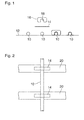
- Fig. 1 are shown in cross-section four parallel tubes 10, which are to be mounted on a flat surface 12.
- the tubes 10 may be heating pipes of a floor heating system.
- the pad 12 is then a floor on which the heating pipes are to be laid.
- an adhesive tape 14 is shown above the second tube from the left, which extends transversely to the longitudinal direction of the tube 10 and is to be pressed against the base 12 with a punch 16 on both sides of the tube 10, as in Fig. 1 is shown in the two tubes to the right.
- the punch 16 has a recess 18 which receives the cross section of the tube 10, while the parts of the punch lying on either side of the recess press against the base 12.
- the adhesive tape 14 in the example shown is a Velcro strip which cooperates with a full-surface or in the form of individual strips laid on the base 12 fleece web.
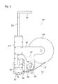
- Fig. 2 two parallel strips 20 of the fleece web are shown, which run at right angles to the pipe 10 to be laid and are fastened to the base 12, for example glued on.
- the width of each strip 20 is significantly greater than the width of the adhesive tape 14, so that when attaching the adhesive tape 14 no precise "aiming" is required.
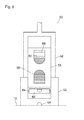
- a setting tool 22 which serves to the adhesive tape 14 in the in Fig. 1 shown manner on the base 12, so that the tube 10 is fixed with it.
- the setting device 22 has a housing 24 in which the punch 16 is guided vertically displaceable. From the housing 24 emerges upwards a drive rod 26, which has a handle 38 at the upper end, on which the entire setting tool 22 can be held and carried by hand.
- the housing 24 has two Zentrierfoue 30, which are shaped similar to the stamp 16 and the in Fig. 3 lie in the direction perpendicular to the plane one behind the other, so that their recesses form a tunnel for the tube 10.
- the setting tool 22 at the point where the tube 10 crosses a strip 20 of the loop tape, put by hand on the tube 10 so that the path of movement of the punch 16 is centered on the tube.
- a supply roll 34 for the adhesive tape 14 and a feed roller 36 are mounted by means of a holder 32.
- the adhesive tape 14 withdrawn from the supply roll 34 is frictionally transported via a tape guide 38 into a space in the interior of the housing 24, which lies below the punch 16.
- a drive arm 40 is guided vertically movable for the feed roller 36.
- a rack 42 is mounted, which meshes with a seated on the shaft of the feed roller 36 gear 44.
- the gear 44 is coupled to the feed roller 36 via a freewheel, so that the feed roller 36 is rotated only in a downward movement of the drive arm 40, while upon an upward movement of the drive arm 40, only the gear 44 is rotated without the feed roller 36 is taken.
- a capping device 46 On the side of the housing 24, which faces the feed roller 36, a capping device 46 is also attached, can be separated with the appropriate length portions of the advanced by the feed roller 36 adhesive tape 14.
- the tube 10 is to be fixed at a certain location on the base 12, then the setting tool 22 in the in Fig. 3 shown manner placed on the tube 10. Subsequently, the handle 28 is pressed down, so that the drive rod 26 enters the housing 24. As a result, the drive arm 40 is moved downwards, so that the feed roller 36 is rotated and the adhesive tape 14 advances, as in Fig. 4 is shown.
- the plunger 16 is extended downwardly in a delayed manner.
- a knife 48 of the capping mechanism 46 is actuated. At a suitable time, therefore, the blade 48 also moves downwardly and moves past a cutting edge so that the advanced portion of the adhesive tape 14 is severed, as in FIG Fig. 5 can be seen.
- the severed portion of the adhesive tape is then forced downwardly to wrap around the tube 10 as it enters the recess 18 of the punch.
- the ends of the severed portion of the adhesive tape protruding on both sides of the tube 10 are pressed against the strip 20 of the loop tape on the base 12, so that the tube is securely fixed on the base.
- the aforementioned impact mechanism ensures that the pressure of the adhesive tape against the pad is always done with the right speed and force.
- a return spring not shown, which, when the force applied to the handle 28 decreases force, the drive rod 26 extends back up out of the housing 24, wherein the carriage with the punch 16th and the knife 48 of the capping device are taken back to their original position.
- the punch 16 and the centering feet 30 are interchangeable and can be exchanged for punch and centering feet, the recesses are adapted to other pipe diameters.
- the rack 42 is removably attached to the drive arm 40. The length of this rack 42 determines the feed path by which the adhesive tape 14 is advanced in a single stroke. By replacing the rack can therefore also be adapted to this feed path to the respective pipe diameter.
- the feed travel may also be greater than the width of the housing 24. The advanced portion of the adhesive tape will then temporarily bulge somewhat upward within the housing 24 and below the punch 16 in the raised position.
- the adhesive tape 14 may also be formed by an adhesive tape, provided that the pad 12 is sufficiently smooth or is covered in a strip-shaped or full-surface with a sufficiently smooth film.
- the adhesive tape 14 may also have an alternating sequence of Velcro tape sections and more flexible sections that are easier to cut through and also better conform to the circumference of the pipe 10. The Velcro sections are then only in the areas that actually come into contact with the loop tape on the pad 12.
- a pivot lever or the like may be provided for actuating the punch 16.
- the setting tool can also have the shape of a car, which is movable in a position in which it engages over the pipe 10 to be fastened, in the longitudinal direction of the tube on the floor.
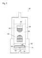
- This in Fig. 6 Setting tool 50 shown has a base 52 which, similar to the centering feet 30 in Fig. 3 can be placed on the substrate and has a tunnel 54 for receiving the pipe to be laid. On both sides of the tunnel 54, the base forms two uprising arms, in which a fork-shaped carriage 56 is guided, which has at its upper end a handle, not shown.
- a magazine 58 in the form is located on the base 52 a rectangular box attached, which receives a stack of precut strips 60 of the adhesive tape (Velcro). Below the lower end of the magazine 58, a punch 62 is vertically movably guided between the upstanding arms of the base 52.
- the punch 62 can be moved in the vertical direction and at the same time rotate by 180 ° about an axis 64 by means of a turning mechanism, as is known, for example, from date stampers.
- this mechanism serves to align the punch surface of the punch in the upper end position so that it points upwards and is pressed against an ink pad, while, when the punch is lowered in a stamping operation, it is turned into a position, in which she points down to the document to be stamped.
- the turning mechanism is used to align the punch 62 so that it assumes a strip 60 of the adhesive tape from the lower end of the stack in the magazine 58 in its upper end position and in its lower end position the acquired strip against the loop tape on the Pad 12 presses to fix the running through the tunnel 54 pipe.
- the magazine 58 has openings 66, which allow to control the level of the magazine.
- the strips 60 are biased downwardly against the lower end of the magazine 58, for example, by means of a weight 68 placed on topmost strip 60 of the stack.
- the sequence of movement of the setting device 50 is in Fig. 7 and 8th shown.
- Fig. 7 the carriage 56 has been pressed down slightly, as a result of which the axis 64 of the punch 62 has also moved downwards.
- the movement of the stamp can be translated into the fast by a gear (not shown) in the first embodiment, so that the lowering speed of the punch is at least in phases larger than that of the carriage 56.
- the punch 62 a rotational movement about the axis 64, so that in Fig. 7 into a recess 70 of the punch in which a single strip 60 (which has been removed from the bottom of the stack) is frictionally engaged is held.
- the stamp also has a tunnel 54 corresponding recess 72 for the pipe to be laid. However, this recess 72 is in Fig. 7 bridged by the strip 60.
- Fig. 8 the punch 62 has been further lowered, so that the recess 70 now points down and the strip is placed on the tube received in the tunnel.
- the tube would then enter into the recess 72 of the punch, while the portions of the strip 60 on both sides of the tube wrap around the tube and are finally pressed by means of the punch against the loop tape.
- the punch 62 performs the reverse sequence of movements to remove a new strip 60 from the magazine.
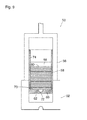
- Fig. 9 shows a view into the interior of the magazine 58 and a vertical section through the punch 62, which is here in its upper end position.
- the recess 70 has the shape of a flat bed whose depth is just about the thickness of a single strip 60.
- Guides 74 are formed on the vertical walls of the magazine, through which the strips 60 are centered, but remain movable in the magazine in a low-friction manner in the vertical direction.
- the punch 62 abuts with its peripheral wall surrounding the recess 70 at the lower ends of the guides 74, and by the weight of the weight 68, the lowermost strip 60 is pressed into the recess 70 with its peripheral edge somewhat wedged in the peripheral wall of the recess 70 becomes.
- Fig. 10 shows the state in which the punch 62 has already lowered slightly and removed from the lower ends of the guides 74.
- pivoted latches 76 prevent the rest of the stack from slipping.
- the latches 76 are also driven by the carriage 76 via a gear, not shown, so that their movement is precisely coordinated with the movement of the punch 62. Due to the mentioned translation, which accelerates the downward movement of the punch 62, moves the frictionally held in the recess 70 strip 60 faster down than the remaining strips of the stack, which are subject only to gravity. In this way arises between the bottom strip 60 and the rest of the stack a gap in which the latch 76 can retract. During the upward movement of the punch 62, the bolts 76 are withdrawn in time, so that the weight 68 can push the next strip into the recess 70.
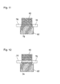
- Fig. 11 shows a section through the punch 62 in the state of the setting tool, which also in Fig. 9 is shown.
- the section plane runs here vertically, but at right angles to the cutting plane in Fig. 9 and 10 , Only the lowermost strips 60 of the stack received in the magazine are shown.
- the lowermost strip is located in the recess of the punch 62.
- the peripheral wall of the recess is interrupted at the points where the latch 76 are located, through slots 78, so that the bars can reach almost directly to the stack of strips 60.
- the bolts 76 move inwards so that they catch the next higher strip 60 before it can slip on its own weight.
- the latches 76 are resilient in the in Fig. 12 are biased shown engagement position, and they are urged outwardly during the upward movement of the punch, so that the next strip can fall into the recess 70.
- jaws are provided which are integrated with the lateral guides 74 and which clampably hold some strips 60 at the lower end of the stack in position while the punch moves downwardly with the strip received therein. When the punch reaches its upper end position again, the jaws are temporarily released, so that the next strip can enter the recess 70.
Landscapes
- Engineering & Computer Science (AREA)
- Physics & Mathematics (AREA)
- Thermal Sciences (AREA)
- Chemical & Material Sciences (AREA)
- Combustion & Propulsion (AREA)
- Mechanical Engineering (AREA)
- General Engineering & Computer Science (AREA)
- Folding Of Thin Sheet-Like Materials, Special Discharging Devices, And Others (AREA)
- Hooks, Suction Cups, And Attachment By Adhesive Means (AREA)
Applications Claiming Priority (1)
| Application Number | Priority Date | Filing Date | Title |
|---|---|---|---|
| DE102012103325A DE102012103325A1 (de) | 2012-04-17 | 2012-04-17 | Verfahren und Vorrichtung zum Befestigen von Rohren |
Publications (3)
| Publication Number | Publication Date |
|---|---|
| EP2653791A2 true EP2653791A2 (fr) | 2013-10-23 |
| EP2653791A3 EP2653791A3 (fr) | 2014-01-15 |
| EP2653791B1 EP2653791B1 (fr) | 2015-04-15 |
Family
ID=48092843
Family Applications (1)
| Application Number | Title | Priority Date | Filing Date |
|---|---|---|---|
| EP13164071.6A Not-in-force EP2653791B1 (fr) | 2012-04-17 | 2013-04-17 | Dispositif de fixation de tubes |
Country Status (2)
| Country | Link |
|---|---|
| EP (1) | EP2653791B1 (fr) |
| DE (1) | DE102012103325A1 (fr) |
Cited By (3)
| Publication number | Priority date | Publication date | Assignee | Title |
|---|---|---|---|---|
| DE202014100134U1 (de) | 2014-01-13 | 2015-04-14 | Walter Henkenjohann | Flauschbandroller |
| EP3144138A1 (fr) * | 2015-09-18 | 2017-03-22 | REHAU AG + Co | couche velcro de support pour système de montage pour système de régulation de température de surface, système de régulation de température de surface comprenant d'une telle couche et procédé mis en oeuvre dans un tel système |
| DE202019100079U1 (de) | 2018-01-09 | 2019-03-07 | herotec GmbH Flächenheizung | Rohrverlegeeinrichtung für eine Flächentemperiervorrichtung und Rohrklemmstreifen für eine derartige Rohrverlegeanordnung |
Families Citing this family (1)
| Publication number | Priority date | Publication date | Assignee | Title |
|---|---|---|---|---|
| DE202019104864U1 (de) * | 2019-09-03 | 2020-11-20 | herotec GmbH Flächenheizung | Verlegevorrichtung für eine Temperiervorrichtung mit Flächentemperier- oder Wärmespeichervorrichtung mit einer derartigen Verlegevorrichtung |
Family Cites Families (14)
| Publication number | Priority date | Publication date | Assignee | Title |
|---|---|---|---|---|
| DE2742402A1 (de) * | 1977-09-21 | 1979-03-29 | Hoechst Ag | Fussbodenheizung |
| DE2815416A1 (de) * | 1978-04-10 | 1979-10-18 | Ekkehard Friedl | Kunststoffrohrleitung fuer fussbodenheizung |
| DE8435744U1 (de) * | 1984-12-06 | 1985-05-09 | Schmidt, Hans, 5165 Hürtgenwald | Elektrisches heizelement |
| DE3509485C1 (de) * | 1985-03-15 | 1986-06-26 | Roth Werke Gmbh, 3563 Dautphetal | Vorrichtung zur Befestigung von in wärmeisolierende Platten einzustoßenden und sich dort verankernden Haltern für Heizrohre von Fußbodenheizungen |
| DE3819156A1 (de) * | 1988-06-04 | 1989-12-07 | Wirsbo Pex Gmbh | Waermetauscheranordnung |
| DE3838544A1 (de) * | 1988-11-14 | 1990-05-17 | Speiser Waerme Technik Alexand | Vorrichtung zur befestigung eines heizrohres |
| DE4009573A1 (de) * | 1990-03-24 | 1991-09-26 | Kolthoff & Co | Halter zur fixierung von rohren, schlaeuchen, kabel und aehnlichen gegenstaenden mit zylindrischer oberflaeche und setzgeraet fuer halter |
| DE29724694U1 (de) * | 1996-11-22 | 2003-03-13 | Fugo Ag, Triboltingen | Verlegevorrichtung für Heizungsrohre o.dgl. |
| DE29708455U1 (de) * | 1997-05-13 | 1998-09-17 | DiTom Verwaltungs GmbH, 98529 Suhl | Vorrichtung zum Befestigen von Fußbodenheizungsrohren auf Kunststoffisolierbahnen |
| DE10117195C1 (de) * | 2001-04-05 | 2003-01-30 | Horst Rock | Verlegevorrichtung zum Verlegen einer elektrisch betriebenen Flächenheizung |
| DE202004011405U1 (de) * | 2004-07-21 | 2004-10-07 | Schütz GmbH & Co. KGaA | Setzgerät für Rohrhalter zum Befestigen von Installationsrohren auf einer nachgiebigen Unterlage |
| DE202005008988U1 (de) * | 2005-06-07 | 2006-05-11 | Winkler, Wolfram, Dipl.-Ing. Dr. | Vorrichtung zum Einstoßen von Haltenadeln |
| FR2898585B1 (fr) * | 2006-03-16 | 2009-02-06 | Airbus France Sas | Dispositif de fixation d'un equipement sensiblement tubulaire sur un matelas d'isolation thermique et phonique d'aeronef |
| DE202010011520U1 (de) * | 2010-08-18 | 2011-11-23 | Uponor Innovation Ab | Klettsystem |
-
2012
- 2012-04-17 DE DE102012103325A patent/DE102012103325A1/de not_active Withdrawn
-
2013
- 2013-04-17 EP EP13164071.6A patent/EP2653791B1/fr not_active Not-in-force
Non-Patent Citations (1)
| Title |
|---|
| None |
Cited By (3)
| Publication number | Priority date | Publication date | Assignee | Title |
|---|---|---|---|---|
| DE202014100134U1 (de) | 2014-01-13 | 2015-04-14 | Walter Henkenjohann | Flauschbandroller |
| EP3144138A1 (fr) * | 2015-09-18 | 2017-03-22 | REHAU AG + Co | couche velcro de support pour système de montage pour système de régulation de température de surface, système de régulation de température de surface comprenant d'une telle couche et procédé mis en oeuvre dans un tel système |
| DE202019100079U1 (de) | 2018-01-09 | 2019-03-07 | herotec GmbH Flächenheizung | Rohrverlegeeinrichtung für eine Flächentemperiervorrichtung und Rohrklemmstreifen für eine derartige Rohrverlegeanordnung |
Also Published As
| Publication number | Publication date |
|---|---|
| DE102012103325A1 (de) | 2013-10-17 |
| EP2653791B1 (fr) | 2015-04-15 |
| EP2653791A3 (fr) | 2014-01-15 |
Similar Documents
| Publication | Publication Date | Title |
|---|---|---|
| DE3885895T2 (de) | System und verfahren zum schneiden und aufwinden eines papierbandes. | |
| EP0281942A1 (fr) | Machine d'enlèvement de fil | |
| EP0003004A1 (fr) | Dispositif pour placer des vis avec des rondelles | |
| EP0069108A2 (fr) | Procédé et dispositif pour fabriquer des corps de matelas soudés | |
| DE2254262C2 (de) | Vorrichtung zum Anbringen von Beschlägen auf Werkstücken | |
| EP2653791B1 (fr) | Dispositif de fixation de tubes | |
| AT518608A2 (de) | Kantenanleimvorrichtung | |
| DE1528050C2 (de) | Einrichtung zum maschinellen Buntaufteilen von Platten | |
| DE1931905U (de) | Vorrichtung zum herstellen von heizkoerpern in tafel- bzw. plattenform. | |
| DE1777137A1 (de) | Verfahren und Vorrichtung zum genauen Einstellen eines Werkstueckes | |
| DE2165664C3 (de) | Vorrichtung zum Umbinden von mehreren Gegenständen mit einer Bandschlaufe | |
| DE1566982C3 (de) | Vorrichtung zum Befestigen von elektrischen Verbindern an einer Platte | |
| DE576818C (de) | Heftklammer und Verfahren zum Eintreiben derselben | |
| DE2265005C3 (de) | Vorrichtung zum Herstellen eines Rolladenpanzers | |
| DE1411483A1 (de) | Verfahren und Maschine zum Verpacken von Gegenstaenden in Folien | |
| DE2712565A1 (de) | Gutbahn-zufuhreinrichtung | |
| CH671585A5 (fr) | ||
| EP1118405A1 (fr) | Appareil de dénudage manuel de tubes | |
| DE3642260A1 (de) | Vorrichtung zum positionieren eines blattstapels auf dem stanztisch einer stanzmaschine | |
| DE1909747B2 (de) | Gerät zum Fädeln von Fadenmaterial durch mindestens eine Öffnung eines Körpers | |
| DE19808538C2 (de) | Schneidvorrichtung und deren Verwendung | |
| EP0659538B1 (fr) | Dispositif pour placer des anses sur des récipients | |
| DE1286738B (de) | Einrichtung zum Verbinden von Werkstuecken an ihren Stirnenden mittels eines Bindemittels, insbesondere von Werkstuecken aus Holz | |
| DE2713012B2 (de) | Vorrichtung zum Ausstanzen von Etiketten mit Bildung von Stapeln zum Bündeln | |
| DE555688C (de) | Nietmaschine mit selbsttaetiger Zufuhr des Nietmaterials |
Legal Events
| Date | Code | Title | Description |
|---|---|---|---|
| PUAI | Public reference made under article 153(3) epc to a published international application that has entered the european phase |
Free format text: ORIGINAL CODE: 0009012 |
|
| AK | Designated contracting states |
Kind code of ref document: A2 Designated state(s): AL AT BE BG CH CY CZ DE DK EE ES FI FR GB GR HR HU IE IS IT LI LT LU LV MC MK MT NL NO PL PT RO RS SE SI SK SM TR |
|
| AX | Request for extension of the european patent |
Extension state: BA ME |
|
| PUAL | Search report despatched |
Free format text: ORIGINAL CODE: 0009013 |
|
| AK | Designated contracting states |
Kind code of ref document: A3 Designated state(s): AL AT BE BG CH CY CZ DE DK EE ES FI FR GB GR HR HU IE IS IT LI LT LU LV MC MK MT NL NO PL PT RO RS SE SI SK SM TR |
|
| AX | Request for extension of the european patent |
Extension state: BA ME |
|
| RIC1 | Information provided on ipc code assigned before grant |
Ipc: F24D 3/14 20060101AFI20131209BHEP Ipc: B65H 35/00 20060101ALI20131209BHEP |
|
| 17P | Request for examination filed |
Effective date: 20140709 |
|
| RBV | Designated contracting states (corrected) |
Designated state(s): AL AT BE BG CH CY CZ DE DK EE ES FI FR GB GR HR HU IE IS IT LI LT LU LV MC MK MT NL NO PL PT RO RS SE SI SK SM TR |
|
| GRAP | Despatch of communication of intention to grant a patent |
Free format text: ORIGINAL CODE: EPIDOSNIGR1 |
|
| RIC1 | Information provided on ipc code assigned before grant |
Ipc: F24D 3/14 20060101AFI20141009BHEP Ipc: B65H 35/00 20060101ALI20141009BHEP |
|
| INTG | Intention to grant announced |
Effective date: 20141024 |
|
| GRAS | Grant fee paid |
Free format text: ORIGINAL CODE: EPIDOSNIGR3 |
|
| GRAA | (expected) grant |
Free format text: ORIGINAL CODE: 0009210 |
|
| AK | Designated contracting states |
Kind code of ref document: B1 Designated state(s): AL AT BE BG CH CY CZ DE DK EE ES FI FR GB GR HR HU IE IS IT LI LT LU LV MC MK MT NL NO PL PT RO RS SE SI SK SM TR |
|
| REG | Reference to a national code |
Ref country code: GB Ref legal event code: FG4D Free format text: NOT ENGLISH Ref country code: CH Ref legal event code: EP |
|
| REG | Reference to a national code |
Ref country code: IE Ref legal event code: FG4D Free format text: LANGUAGE OF EP DOCUMENT: GERMAN |
|
| REG | Reference to a national code |
Ref country code: AT Ref legal event code: REF Ref document number: 722212 Country of ref document: AT Kind code of ref document: T Effective date: 20150515 |
|
| REG | Reference to a national code |
Ref country code: DE Ref legal event code: R096 Ref document number: 502013000548 Country of ref document: DE Effective date: 20150528 |
|
| REG | Reference to a national code |
Ref country code: CH Ref legal event code: NV Representative=s name: TROESCH SCHEIDEGGER WERNER AG, CH |
|
| REG | Reference to a national code |
Ref country code: LT Ref legal event code: MG4D |
|
| PG25 | Lapsed in a contracting state [announced via postgrant information from national office to epo] |
Ref country code: NO Free format text: LAPSE BECAUSE OF FAILURE TO SUBMIT A TRANSLATION OF THE DESCRIPTION OR TO PAY THE FEE WITHIN THE PRESCRIBED TIME-LIMIT Effective date: 20150715 Ref country code: ES Free format text: LAPSE BECAUSE OF FAILURE TO SUBMIT A TRANSLATION OF THE DESCRIPTION OR TO PAY THE FEE WITHIN THE PRESCRIBED TIME-LIMIT Effective date: 20150415 Ref country code: PT Free format text: LAPSE BECAUSE OF FAILURE TO SUBMIT A TRANSLATION OF THE DESCRIPTION OR TO PAY THE FEE WITHIN THE PRESCRIBED TIME-LIMIT Effective date: 20150817 Ref country code: LT Free format text: LAPSE BECAUSE OF FAILURE TO SUBMIT A TRANSLATION OF THE DESCRIPTION OR TO PAY THE FEE WITHIN THE PRESCRIBED TIME-LIMIT Effective date: 20150415 Ref country code: FI Free format text: LAPSE BECAUSE OF FAILURE TO SUBMIT A TRANSLATION OF THE DESCRIPTION OR TO PAY THE FEE WITHIN THE PRESCRIBED TIME-LIMIT Effective date: 20150415 Ref country code: HR Free format text: LAPSE BECAUSE OF FAILURE TO SUBMIT A TRANSLATION OF THE DESCRIPTION OR TO PAY THE FEE WITHIN THE PRESCRIBED TIME-LIMIT Effective date: 20150415 |
|
| PG25 | Lapsed in a contracting state [announced via postgrant information from national office to epo] |
Ref country code: IS Free format text: LAPSE BECAUSE OF FAILURE TO SUBMIT A TRANSLATION OF THE DESCRIPTION OR TO PAY THE FEE WITHIN THE PRESCRIBED TIME-LIMIT Effective date: 20150815 Ref country code: GR Free format text: LAPSE BECAUSE OF FAILURE TO SUBMIT A TRANSLATION OF THE DESCRIPTION OR TO PAY THE FEE WITHIN THE PRESCRIBED TIME-LIMIT Effective date: 20150716 Ref country code: LV Free format text: LAPSE BECAUSE OF FAILURE TO SUBMIT A TRANSLATION OF THE DESCRIPTION OR TO PAY THE FEE WITHIN THE PRESCRIBED TIME-LIMIT Effective date: 20150415 Ref country code: RS Free format text: LAPSE BECAUSE OF FAILURE TO SUBMIT A TRANSLATION OF THE DESCRIPTION OR TO PAY THE FEE WITHIN THE PRESCRIBED TIME-LIMIT Effective date: 20150415 |
|
| REG | Reference to a national code |
Ref country code: DE Ref legal event code: R097 Ref document number: 502013000548 Country of ref document: DE |
|
| REG | Reference to a national code |
Ref country code: IE Ref legal event code: MM4A |
|
| PG25 | Lapsed in a contracting state [announced via postgrant information from national office to epo] |
Ref country code: IT Free format text: LAPSE BECAUSE OF FAILURE TO SUBMIT A TRANSLATION OF THE DESCRIPTION OR TO PAY THE FEE WITHIN THE PRESCRIBED TIME-LIMIT Effective date: 20150415 Ref country code: EE Free format text: LAPSE BECAUSE OF FAILURE TO SUBMIT A TRANSLATION OF THE DESCRIPTION OR TO PAY THE FEE WITHIN THE PRESCRIBED TIME-LIMIT Effective date: 20150415 Ref country code: MC Free format text: LAPSE BECAUSE OF FAILURE TO SUBMIT A TRANSLATION OF THE DESCRIPTION OR TO PAY THE FEE WITHIN THE PRESCRIBED TIME-LIMIT Effective date: 20150415 Ref country code: DK Free format text: LAPSE BECAUSE OF FAILURE TO SUBMIT A TRANSLATION OF THE DESCRIPTION OR TO PAY THE FEE WITHIN THE PRESCRIBED TIME-LIMIT Effective date: 20150415 |
|
| PLBE | No opposition filed within time limit |
Free format text: ORIGINAL CODE: 0009261 |
|
| STAA | Information on the status of an ep patent application or granted ep patent |
Free format text: STATUS: NO OPPOSITION FILED WITHIN TIME LIMIT |
|
| PG25 | Lapsed in a contracting state [announced via postgrant information from national office to epo] |
Ref country code: RO Free format text: LAPSE BECAUSE OF NON-PAYMENT OF DUE FEES Effective date: 20150415 Ref country code: PL Free format text: LAPSE BECAUSE OF FAILURE TO SUBMIT A TRANSLATION OF THE DESCRIPTION OR TO PAY THE FEE WITHIN THE PRESCRIBED TIME-LIMIT Effective date: 20150415 Ref country code: SK Free format text: LAPSE BECAUSE OF FAILURE TO SUBMIT A TRANSLATION OF THE DESCRIPTION OR TO PAY THE FEE WITHIN THE PRESCRIBED TIME-LIMIT Effective date: 20150415 Ref country code: CZ Free format text: LAPSE BECAUSE OF FAILURE TO SUBMIT A TRANSLATION OF THE DESCRIPTION OR TO PAY THE FEE WITHIN THE PRESCRIBED TIME-LIMIT Effective date: 20150415 |
|
| 26N | No opposition filed |
Effective date: 20160118 |
|
| REG | Reference to a national code |
Ref country code: FR Ref legal event code: PLFP Year of fee payment: 4 |
|
| PG25 | Lapsed in a contracting state [announced via postgrant information from national office to epo] |
Ref country code: IE Free format text: LAPSE BECAUSE OF NON-PAYMENT OF DUE FEES Effective date: 20150417 |
|
| PG25 | Lapsed in a contracting state [announced via postgrant information from national office to epo] |
Ref country code: SI Free format text: LAPSE BECAUSE OF FAILURE TO SUBMIT A TRANSLATION OF THE DESCRIPTION OR TO PAY THE FEE WITHIN THE PRESCRIBED TIME-LIMIT Effective date: 20150415 |
|
| PG25 | Lapsed in a contracting state [announced via postgrant information from national office to epo] |
Ref country code: MT Free format text: LAPSE BECAUSE OF FAILURE TO SUBMIT A TRANSLATION OF THE DESCRIPTION OR TO PAY THE FEE WITHIN THE PRESCRIBED TIME-LIMIT Effective date: 20150415 |
|
| REG | Reference to a national code |
Ref country code: FR Ref legal event code: PLFP Year of fee payment: 5 |
|
| PG25 | Lapsed in a contracting state [announced via postgrant information from national office to epo] |
Ref country code: HU Free format text: LAPSE BECAUSE OF FAILURE TO SUBMIT A TRANSLATION OF THE DESCRIPTION OR TO PAY THE FEE WITHIN THE PRESCRIBED TIME-LIMIT; INVALID AB INITIO Effective date: 20130417 Ref country code: BG Free format text: LAPSE BECAUSE OF FAILURE TO SUBMIT A TRANSLATION OF THE DESCRIPTION OR TO PAY THE FEE WITHIN THE PRESCRIBED TIME-LIMIT Effective date: 20150415 |
|
| PG25 | Lapsed in a contracting state [announced via postgrant information from national office to epo] |
Ref country code: SE Free format text: LAPSE BECAUSE OF FAILURE TO SUBMIT A TRANSLATION OF THE DESCRIPTION OR TO PAY THE FEE WITHIN THE PRESCRIBED TIME-LIMIT Effective date: 20150415 Ref country code: CY Free format text: LAPSE BECAUSE OF FAILURE TO SUBMIT A TRANSLATION OF THE DESCRIPTION OR TO PAY THE FEE WITHIN THE PRESCRIBED TIME-LIMIT Effective date: 20150415 |
|
| PG25 | Lapsed in a contracting state [announced via postgrant information from national office to epo] |
Ref country code: BE Free format text: LAPSE BECAUSE OF NON-PAYMENT OF DUE FEES Effective date: 20150430 |
|
| PG25 | Lapsed in a contracting state [announced via postgrant information from national office to epo] |
Ref country code: TR Free format text: LAPSE BECAUSE OF FAILURE TO SUBMIT A TRANSLATION OF THE DESCRIPTION OR TO PAY THE FEE WITHIN THE PRESCRIBED TIME-LIMIT Effective date: 20150415 |
|
| PG25 | Lapsed in a contracting state [announced via postgrant information from national office to epo] |
Ref country code: LU Free format text: LAPSE BECAUSE OF NON-PAYMENT OF DUE FEES Effective date: 20150417 |
|
| GBPC | Gb: european patent ceased through non-payment of renewal fee |
Effective date: 20170417 |
|
| PG25 | Lapsed in a contracting state [announced via postgrant information from national office to epo] |
Ref country code: GB Free format text: LAPSE BECAUSE OF NON-PAYMENT OF DUE FEES Effective date: 20170417 |
|
| REG | Reference to a national code |
Ref country code: FR Ref legal event code: PLFP Year of fee payment: 6 |
|
| PG25 | Lapsed in a contracting state [announced via postgrant information from national office to epo] |
Ref country code: SM Free format text: LAPSE BECAUSE OF FAILURE TO SUBMIT A TRANSLATION OF THE DESCRIPTION OR TO PAY THE FEE WITHIN THE PRESCRIBED TIME-LIMIT Effective date: 20150415 |
|
| PG25 | Lapsed in a contracting state [announced via postgrant information from national office to epo] |
Ref country code: MK Free format text: LAPSE BECAUSE OF FAILURE TO SUBMIT A TRANSLATION OF THE DESCRIPTION OR TO PAY THE FEE WITHIN THE PRESCRIBED TIME-LIMIT Effective date: 20150415 |
|
| PG25 | Lapsed in a contracting state [announced via postgrant information from national office to epo] |
Ref country code: AL Free format text: LAPSE BECAUSE OF FAILURE TO SUBMIT A TRANSLATION OF THE DESCRIPTION OR TO PAY THE FEE WITHIN THE PRESCRIBED TIME-LIMIT Effective date: 20150415 |
|
| PGFP | Annual fee paid to national office [announced via postgrant information from national office to epo] |
Ref country code: FR Payment date: 20190423 Year of fee payment: 7 |
|
| PGFP | Annual fee paid to national office [announced via postgrant information from national office to epo] |
Ref country code: CH Payment date: 20200522 Year of fee payment: 8 |
|
| PG25 | Lapsed in a contracting state [announced via postgrant information from national office to epo] |
Ref country code: FR Free format text: LAPSE BECAUSE OF NON-PAYMENT OF DUE FEES Effective date: 20200430 |
|
| PG25 | Lapsed in a contracting state [announced via postgrant information from national office to epo] |
Ref country code: LI Free format text: LAPSE BECAUSE OF NON-PAYMENT OF DUE FEES Effective date: 20210430 Ref country code: CH Free format text: LAPSE BECAUSE OF NON-PAYMENT OF DUE FEES Effective date: 20210430 |
|
| PGFP | Annual fee paid to national office [announced via postgrant information from national office to epo] |
Ref country code: NL Payment date: 20240422 Year of fee payment: 12 |
|
| PGFP | Annual fee paid to national office [announced via postgrant information from national office to epo] |
Ref country code: DE Payment date: 20240418 Year of fee payment: 12 |
|
| PGFP | Annual fee paid to national office [announced via postgrant information from national office to epo] |
Ref country code: AT Payment date: 20240417 Year of fee payment: 12 |
|
| REG | Reference to a national code |
Ref country code: DE Ref legal event code: R119 Ref document number: 502013000548 Country of ref document: DE |
|
| REG | Reference to a national code |
Ref country code: NL Ref legal event code: MM Effective date: 20250501 |
|
| REG | Reference to a national code |
Ref country code: AT Ref legal event code: MM01 Ref document number: 722212 Country of ref document: AT Kind code of ref document: T Effective date: 20250417 |
|
| PG25 | Lapsed in a contracting state [announced via postgrant information from national office to epo] |
Ref country code: DE Free format text: LAPSE BECAUSE OF NON-PAYMENT OF DUE FEES Effective date: 20251104 |
|
| PG25 | Lapsed in a contracting state [announced via postgrant information from national office to epo] |
Ref country code: AT Free format text: LAPSE BECAUSE OF NON-PAYMENT OF DUE FEES Effective date: 20250417 |
|
| PG25 | Lapsed in a contracting state [announced via postgrant information from national office to epo] |
Ref country code: NL Free format text: LAPSE BECAUSE OF NON-PAYMENT OF DUE FEES Effective date: 20250501 |