EP2653794B2 - Pipe connector - Google Patents
Pipe connector Download PDFInfo
- Publication number
- EP2653794B2 EP2653794B2 EP13163342.2A EP13163342A EP2653794B2 EP 2653794 B2 EP2653794 B2 EP 2653794B2 EP 13163342 A EP13163342 A EP 13163342A EP 2653794 B2 EP2653794 B2 EP 2653794B2
- Authority
- EP
- European Patent Office
- Prior art keywords
- pipeline
- pipe
- pipe connector
- section
- housing part
- Prior art date
- Legal status (The legal status is an assumption and is not a legal conclusion. Google has not performed a legal analysis and makes no representation as to the accuracy of the status listed.)
- Active
Links
Images


Classifications
-
- F—MECHANICAL ENGINEERING; LIGHTING; HEATING; WEAPONS; BLASTING
- F24—HEATING; RANGES; VENTILATING
- F24D—DOMESTIC- OR SPACE-HEATING SYSTEMS, e.g. CENTRAL HEATING SYSTEMS; DOMESTIC HOT-WATER SUPPLY SYSTEMS; ELEMENTS OR COMPONENTS THEREFOR
- F24D19/00—Details
- F24D19/0097—Casings or frame structures for hydraulic components
-
- F—MECHANICAL ENGINEERING; LIGHTING; HEATING; WEAPONS; BLASTING
- F16—ENGINEERING ELEMENTS AND UNITS; GENERAL MEASURES FOR PRODUCING AND MAINTAINING EFFECTIVE FUNCTIONING OF MACHINES OR INSTALLATIONS; THERMAL INSULATION IN GENERAL
- F16L—PIPES; JOINTS OR FITTINGS FOR PIPES; SUPPORTS FOR PIPES, CABLES OR PROTECTIVE TUBING; MEANS FOR THERMAL INSULATION IN GENERAL
- F16L41/00—Branching pipes; Joining pipes to walls
- F16L41/02—Branch units, e.g. made in one piece, welded, riveted
- F16L41/03—Branch units, e.g. made in one piece, welded, riveted comprising junction pieces for four or more pipe members
-
- F—MECHANICAL ENGINEERING; LIGHTING; HEATING; WEAPONS; BLASTING
- F16—ENGINEERING ELEMENTS AND UNITS; GENERAL MEASURES FOR PRODUCING AND MAINTAINING EFFECTIVE FUNCTIONING OF MACHINES OR INSTALLATIONS; THERMAL INSULATION IN GENERAL
- F16L—PIPES; JOINTS OR FITTINGS FOR PIPES; SUPPORTS FOR PIPES, CABLES OR PROTECTIVE TUBING; MEANS FOR THERMAL INSULATION IN GENERAL
- F16L43/00—Bends; Siphons
- F16L43/008—Bends; Siphons made from plastic material
-
- F—MECHANICAL ENGINEERING; LIGHTING; HEATING; WEAPONS; BLASTING
- F16—ENGINEERING ELEMENTS AND UNITS; GENERAL MEASURES FOR PRODUCING AND MAINTAINING EFFECTIVE FUNCTIONING OF MACHINES OR INSTALLATIONS; THERMAL INSULATION IN GENERAL
- F16L—PIPES; JOINTS OR FITTINGS FOR PIPES; SUPPORTS FOR PIPES, CABLES OR PROTECTIVE TUBING; MEANS FOR THERMAL INSULATION IN GENERAL
- F16L47/00—Connecting arrangements or other fittings specially adapted to be made of plastics or to be used with pipes made of plastics
- F16L47/26—Connecting arrangements or other fittings specially adapted to be made of plastics or to be used with pipes made of plastics for branching pipes; for joining pipes to walls; Adaptors therefor
- F16L47/32—Branch units, e.g. made in one piece, welded, riveted
-
- F—MECHANICAL ENGINEERING; LIGHTING; HEATING; WEAPONS; BLASTING
- F16—ENGINEERING ELEMENTS AND UNITS; GENERAL MEASURES FOR PRODUCING AND MAINTAINING EFFECTIVE FUNCTIONING OF MACHINES OR INSTALLATIONS; THERMAL INSULATION IN GENERAL
- F16L—PIPES; JOINTS OR FITTINGS FOR PIPES; SUPPORTS FOR PIPES, CABLES OR PROTECTIVE TUBING; MEANS FOR THERMAL INSULATION IN GENERAL
- F16L9/00—Rigid pipes
- F16L9/22—Pipes composed of a plurality of segments
-
- F—MECHANICAL ENGINEERING; LIGHTING; HEATING; WEAPONS; BLASTING
- F24—HEATING; RANGES; VENTILATING
- F24D—DOMESTIC- OR SPACE-HEATING SYSTEMS, e.g. CENTRAL HEATING SYSTEMS; DOMESTIC HOT-WATER SUPPLY SYSTEMS; ELEMENTS OR COMPONENTS THEREFOR
- F24D19/00—Details
- F24D19/0002—Means for connecting central heating radiators to circulation pipes
Definitions
- the present invention relates to a pipe connector for a domestic installation having a housing and having at least one fluid-flowable pipe, wherein the housing consists of plastic and wherein at the ends of the at least one pipe connections for connection to further pipes are provided, wherein the housing at least two housing parts, wherein the first housing part has a lower pipeline section of the at least one pipeline, wherein the second housing part has an upper pipeline section of the at least one pipeline, wherein the lower pipeline section and / or the upper pipeline section of the at least one pipeline has at least one corner region, wherein a rounding is provided in the at least one corner region, wherein at least one further pipeline is provided, and wherein the first pipeline, the at least one further pipeline in an intersection region crosses. Furthermore, the invention relates to the use of a pipe connector in a drinking water, heating or cooling system.
- Pipe connection systems for domestic installation, in particular for heating systems, are usually made of gunmetal.
- gunmetal In addition to pipe connectors that connect two lines with each other, systems with four terminals are known, which are used for example as a connector of intersecting pipes.
- gunmetal is expensive to manufacture and also has the disadvantage that the production of a component, which is usually done by casting, due to the high copper content of gunmetal is very complex.
- the DE 2 412 303 relates to a piping manifold body for heating systems, which can be used optionally for single-pipe or twin-pipe central heating systems.
- An insert which can be installed in the manifold, separates two pipes in the area where they intersect.
- this manifold has the disadvantage that on the one hand it is very expensive to manufacture.
- a pipe constriction occurs in the crossing area, which causes a significant loss of flow.
- Pipe connectors made of plastic produced by casting are cast in one piece in the prior art by means of injection molding. In order to realize pipelines that can not be demoulded in a direction perpendicular to the mold, slides are used during the casting, which are removed from the mold in the direction of the longitudinal axis of the pipeline.
- the EP 2 420 629 A1 discloses a plastic housing consisting of two shell-shaped parts, which are produced by die-casting and which enclose a drinking water-conducting functional unit. In this case, the housing itself does not come into contact with the fluid flowing through the functional unit.
- WO 2011/066612 A1 discloses a system of fluid conduit components in an air conditioning system.
- the components may have plastic housing and connectable housing halves.
- the present invention has the object to provide a flow-optimized pipe connector made of plastic.
- the first housing part in the crossing region has a pipe segment of the first pipe and that the at least one further pipe in the crossing region has a ramp which is adapted to a fluid which flows through the at least one further pipe via the pipe segment to conduct the first pipeline.
- each pipeline section forms part of the cross section of the pipeline.
- a pipeline section is formed as a shell, which forms 50% of the cross section of the pipeline.
- the at least one pipe of the pipe connector may be formed, for example, as a straight connection or as a pipe bend or T-piece.
- a pipeline can be made by injection molding of a plastic housing consisting of two housing parts and that by the production of the pipe connector in at least two housing parts, which are joined together in a second step, a complex structure of the pipe connector can be realized.
- An injection-molded plastic housing is simple and inexpensive to manufacture. In addition, in contrast to housings, which are produced in a part by injection molding, no problems in demolding particular of parts having a complex structure, from the mold on.
- the lower pipeline section of the at least one pipeline can have at least one corner region, wherein a fillet is provided in the at least one corner region. This rounding off can reduce the formation of laminar flow vortices in the at least one pipeline and thus further optimize the flow behavior of the fluid within this pipeline.
- the upper pipe section of the at least one pipe may have at least one corner region, wherein in the at least one corner region, a fillet is provided.
- the at least two housing parts of the housing according to the invention are permanently joined together by gluing or welding.
- ultrasonic welding, vibration welding, heating element welding, laser welding or infrared welding are methods that are suitable for these purposes. Any other common joining method for plastic parts can also be used for this purpose.
- the lower pipe section of the first housing part and the upper pipe section of the second housing part together form the at least one pipeline.
- the pipe connector according to the invention can be installed to save space in a piping system in which the pipes are close together.
- heater body connections and floor heating pipes often have a small distance between the individual pipes.
- the lower and / or the upper pipeline section of the at least one further pipeline have at least one corner region, wherein a fillet is provided in the at least one corner region.
- the at least one further pipeline can be designed, for example, as a pipe bend or as a T-piece.
- the flow resistance of the fluid flowing through the at least one further pipeline can also be reduced further.
- the first pipe crosses the at least one further pipe in an intersection region.
- the first housing part in the crossing region on a pipe segment of the first pipe.
- the second housing part in the crossing region on a recess. In the connected state of the two housing parts thereby a cavity is formed above the pipe segment, so that it can be ensured that the fluid can flow around the pipe segment of the first pipe on one side.
- the at least one further pipeline has a ramp in the crossing area, which is suitable for directing a fluid which flows through the at least one further pipeline via the pipeline segment of the first pipeline.
- the ramp sets as little resistance to the flowing fluid, so that the flow behavior within the crossing region can be further optimized.
- a rounding is provided in at least one area of the edges of the ramp.
- the formation of laminar flow vortices at the edges can be further reduced by the rounding off.
- the rounding of at least one edge also contributes to the reduction of the flow resistance.
- the angle in the crossing region between the first pipeline and the at least one further pipeline is between 45 ° and 135 °.
- the angle is 90 °.
- the pipe connector can be easily installed in a pipe system.
- the crossing region may be designed so that no or only slight cross-sectional changes occur in both pipelines. If a cross-sectional change does occur, the change in cross section of the first pipeline in the crossing region is preferably less than 20%, in particular less than 10%. This ensures that the flow behavior of the fluid is not influenced too much, for example by a narrowing of the flow cross-section. Thus, the fluid can flow evenly through the first pipeline.
- the change in cross section of the at least one further pipeline in the crossing region may be less than 20%, in particular less than 10%.
- the pipe connector according to the invention can be particularly easily installed in piping systems in the floor or in the wall, in particular at locations where lines intersect.
- the at least one further pipeline has, in a next embodiment, at least two connections for the connection of the pipe connector with at least two further pipes.
- These connections can be designed as a compression connector or as a threaded connection.
- any other type of connection of two pipes, such as flanges or sleeves, may be provided for connection to other pipelines.
- a pipe connector according to any of the embodiments described above is preferably used in a drinking water, heating or cooling system.
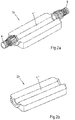
- Fig. 1 shows a pipe connector with a housing 2 and with a fluid-flowable pipe 4.
- the housing 2 has a first housing part 18 and a second housing part 20, wherein the two housing parts 18 and 20 are joined together by gluing or welding.
- the pipe 4, which is formed from the two housing parts 18 and 20, is formed as a straight pipe 12.
- connections 6 and 8 of the compound of the pipe 4 with other pipes which are not shown here.
- These connections can be formed, for example, as a compression connector or as a threaded connection.
- any other type of connection of two pipes, such as flanges or sleeves, may be provided for connection to other pipelines.
- Fig. 2a shows a first housing part 18 of a pipe connector.
- the first housing part 18 has a lower pipe section 4 ', wherein at the ends of the lower pipe section 4' terminals 6 and 8 are provided for connection to other pipes, which are not shown here.
- the lower pipe section 4 ' is formed as a straight pipe section.
- Fig. 2b shows a second housing part 20 of a pipe connector.
- the second housing part 20 has an upper pipe section 4 ", and this upper pipe section 4" is also formed as a straight pipe section.
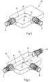
- Fig. 3 shows a first housing part 18 of a pipe connector with a lower pipe section 14 'of a first pipe 14.
- the pipe 14 is formed in this embodiment as a pipe bend.
- the first housing part 18 has a lower pipe section 14 'of the pipe bend 14 and connections 6 and 8 for the connection of the pipe bend 14 with further pipes.
- a fillet 24 is provided, which optimizes the flow behavior of the fluid flowing through the pipe bend 14.
- a second housing part which is not shown here, has a corresponding upper pipe section (correspondingly denoted by 14 ") of the pipe bend, so that the pipe bend 14 is formed by the joining of the two housing parts.
- Fig. 4 shows a first housing part 18 of a pipe connector, wherein the pipe 16 is formed as a T-piece.
- the first housing part 18 has a lower pipe section 16 'and connections 6, 8 and 10 for connection to further pipelines.
- Fillets 24 are provided in corner regions 22 of the lower pipe section 16 ', which reduce the occurrence of disturbances of the laminar flow of the fluid flowing through the pipe 16 and thus optimize the flow behavior within the pipe 16.
- the second housing part has an upper pipe section (here corresponding to 16 "), which is designed to be a T-piece in accordance with the previously described lower pipe section 16 '.
- a first housing part 18 of a first embodiment shows Fig. 5a ,
- a further pipe 28 is provided, wherein both pipes 4 and 28 are formed as straight pipes, which intersect in an intersection region 36.
- the first housing part 18 has a lower pipe section 12 'of the first pipe 12 and a lower pipe section 28' of the second pipe 28.
- the angle a between the lower pipe section 12 'and the lower pipe section 28' is 90 °.
- the first housing part 18 has a pipeline segment 5 of the first pipeline 4.
- a ramp 38 is provided in the crossing region 36, which has a one-sided flow around the pipe segment 5 of the first pipe 4.
- a ramp 38 is provided in the crossing region 36, which allows a one-sided flow around the pipe segment 5 of the first pipe 4.
- fillets 24 are provided in the region of the edges 40 of the ramp 38.
- Fig. 5b shows a second housing part 20 of the embodiment described above.
- the second housing part 20 has an upper pipe section 4 "of the first pipe 4 and an upper pipe section 28" of the second pipe 28, the upper pipe section 4 "of the first pipe 4 crossing the upper pipe section 28" of the second pipe 28 in an intersection area 36 , In the crossing region 36, the second housing part 20 has a recess 42.
- the housing parts 18, 20 form the Fig. 5a and 5b the pipes 4 and 28.
- the recess 42 in the crossing region 36 of the second housing part 20 can be ensured that the fluid flowing through the second pipe 28, the pipe segment 5 of the first pipe 4 can flow around, the flow cross-section is maintained or only slightly by 20%, preferably to 10%, can be reduced.
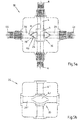
- Fig. 6a and b show a first housing part 18 and a second housing part 20 of a second embodiment of a pipe connector according to the invention, which put together a in Fig. 7 illustrated Form housing 2.
- two pipes 16 and 45 are provided, which are both formed as a tee.
- Fig. 6a shows the first housing part 18 with lower pipe sections 16 'and 45' of the pipes 16 and 45.
- fillets 24 are provided which minimize the flow resistance for the fluid flowing through the pipes 16 and 45.
- the lower pipe section 16 crosseses the lower pipe section 45'. The angle between the intersecting pipe sections is 90 °.
- the first housing part 18 has a pipeline segment 5 of the first pipeline 16. So that the fluid flowing through the second pipeline 45 can optimally flow around the pipeline segment 5 of the first pipeline 16 in the intersection region 36, a ramp 38 is provided which guides the fluid via the pipeline segment 5. In order to minimize the flow resistance, fillets 24 are provided in the region of the edges 40 of the ramp 38. At the ends of the lower pipe sections 16 'and 45', the first housing part 18 has connections 6, 8, 10, 44, 46 and 48 for connection to further pipelines.
- Fig. 6b shows a second housing part 20 of the second embodiment of the pipe connector according to the invention.
- the second housing part 20 has an upper pipe section 16 "of the first pipe 16 and an upper pipe section 45" of the second pipe 45, the upper pipe section 16 "crossing the upper pipe section 45" in an intersection area 36.
- corner regions 22 of the upper pipe sections 16 "and 45" fillets 24 are provided which further optimize the flow behavior of the fluid flowing through the pipe 16 and 45.
- the second housing part 20 has a recess 42.
- the two housing parts 18 and 20 form the Fig. 6a and 6b the pipes 16 and 45.
- Fig. 7 shows the housing 2 of the second embodiment, wherein the two housing parts 18, 20 of the Fig. 6a and 6b are joined together.
- the pipe connector shown has at the ends of the pipes 16 and 45 ports 6, 8, 10, 44, 46 and 48 for connection to other pipes, which are not shown here, on.
- This embodiment of a pipe connector according to the invention can be particularly well integrated into the laying of pipes in the floor or in the wall due to its low height.
Landscapes
- Engineering & Computer Science (AREA)
- General Engineering & Computer Science (AREA)
- Mechanical Engineering (AREA)
- Physics & Mathematics (AREA)
- Thermal Sciences (AREA)
- Chemical & Material Sciences (AREA)
- Combustion & Propulsion (AREA)
- Branch Pipes, Bends, And The Like (AREA)
- Quick-Acting Or Multi-Walled Pipe Joints (AREA)
Description
Die vorliegende Erfindung betrifft einen Rohrverbinder für eine Hausinstallation mit einem Gehäuse und mit mindestens einer mit einem Fluid durchströmbaren Rohrleitung, wobei das Gehäuse aus Kunststoff besteht und wobei an den Enden der mindestens einen Rohrleitung Anschlüsse für die Verbindung mit weiteren Rohrleitungen vorgesehen sind, wobei das Gehäuse mindestens zwei Gehäuseteile aufweist, wobei der erste Gehäuseteil einen unteren Rohrleitungsabschnitt der mindestens einen Rohrleitung aufweist, wobei der zweite Gehäuseteil einen oberen Rohrleitungsabschnitt der mindestens einen Rohrleitung aufweist, wobei der untere Rohrleitungsabschnitt und/oder der obere Rohrleitungsabschnitt der mindestens einen Rohrleitung mindestens einen Eckbereich aufweist, wobei in dem mindestens einen Eckbereich eine Ausrundung vorgesehen ist, wobei mindestens eine weitere Rohrleitung vorgesehen ist, und wobei die erste Rohrleitung die mindestens eine weitere Rohrleitung in einem Kreuzungsbereich kreuzt. Ferner betrifft die Erfindung die Verwendung eines Rohrverbinders in einem Trinkwasser-, Heizungs- oder Kühlsystem.The present invention relates to a pipe connector for a domestic installation having a housing and having at least one fluid-flowable pipe, wherein the housing consists of plastic and wherein at the ends of the at least one pipe connections for connection to further pipes are provided, wherein the housing at least two housing parts, wherein the first housing part has a lower pipeline section of the at least one pipeline, wherein the second housing part has an upper pipeline section of the at least one pipeline, wherein the lower pipeline section and / or the upper pipeline section of the at least one pipeline has at least one corner region, wherein a rounding is provided in the at least one corner region, wherein at least one further pipeline is provided, and wherein the first pipeline, the at least one further pipeline in an intersection region crosses. Furthermore, the invention relates to the use of a pipe connector in a drinking water, heating or cooling system.
Rohrverbindungssysteme für die Hausinstallation, insbesondere für Heizungssysteme, werden üblicherweise aus Rotguss hergestellt. Neben Rohrverbindern, die zwei Leitungen miteinander verbinden, sind auch Systeme mit vier Anschlüssen bekannt, die beispielsweise als Verbindungsstück von sich kreuzenden Rohrleitungen eingesetzt werden. Rotguss ist jedoch teuer in der Herstellung und hat darüber hinaus den Nachteil, dass die Herstellung eines Bauteils, die üblicherweise im Gussverfahren erfolgt, aufgrund des hohen Kupfergehaltes von Rotguss sehr aufwändig ist.Pipe connection systems for domestic installation, in particular for heating systems, are usually made of gunmetal. In addition to pipe connectors that connect two lines with each other, systems with four terminals are known, which are used for example as a connector of intersecting pipes. However, gunmetal is expensive to manufacture and also has the disadvantage that the production of a component, which is usually done by casting, due to the high copper content of gunmetal is very complex.
Die
Neben Verbindungsbauteilen aus Rotguss sind auch Rohrverbinder aus Kunststoff bekannt. Diese haben jedoch, insbesondere wenn sie Winkel oder Abzweigungen aufweisen, den Nachteil, dass große Strömungsverluste des sie durchströmenden Fluids auftreten. Im Gussverfahren hergestellte Rohrverbinder aus Kunststoff werden im Stand der Technik mittels Spritzgießen in einem Teil gegossen. Um Rohrleitungen zu realisieren, die nicht in einer Richtung senkrecht zur Gussform entformt werden können, werden während des Gießens Schieber eingesetzt, die in Richtung der Längsachse der Rohrleitung entformt werden.In addition to connecting components made of gunmetal and plastic pipe connectors are known. However, these have, in particular if they have angles or branches, the disadvantage that large flow losses of the fluid flowing through them occur. Pipe connectors made of plastic produced by casting are cast in one piece in the prior art by means of injection molding. In order to realize pipelines that can not be demoulded in a direction perpendicular to the mold, slides are used during the casting, which are removed from the mold in the direction of the longitudinal axis of the pipeline.
Des Weiteren ist bekannt, Werkstücke aus Kunststoff in zwei Teilen zu gießen.Furthermore, it is known to pour workpieces of plastic in two parts.
Die
In der
Ausgehend von diesem Stand der Technik liegt der vorliegenden Erfindung die Aufgabe zugrunde einen strömungsoptimierten Rohrverbinder aus Kunststoff anzugeben.Based on this prior art, the present invention has the object to provide a flow-optimized pipe connector made of plastic.
Diese Aufgabe wird dadurch gelöst, dass der erste Gehäuseteil im Kreuzungsbereich ein Rohrleitungssegment der ersten Rohrleitung aufweist und dass die mindestens eine weitere Rohrleitung im Kreuzungsbereich eine Rampe aufweist, die dazu geeignet ist, ein Fluid, welches die mindestens eine weitere Rohrleitung durchströmt, über das Rohrleitungssegment der ersten Rohrleitung zu leiten.This object is achieved in that the first housing part in the crossing region has a pipe segment of the first pipe and that the at least one further pipe in the crossing region has a ramp which is adapted to a fluid which flows through the at least one further pipe via the pipe segment to conduct the first pipeline.
Jeder Rohrleitungsabschnitt stellt dabei einen Teil des Querschnitts der Rohrleitung dar. In bevorzugter Weise ist ein Rohrleitungsabschnitt als Schale ausgebildet, die 50% des Querschnitts der Rohrleitung bildet.In this case, each pipeline section forms part of the cross section of the pipeline. In a preferred manner, a pipeline section is formed as a shell, which forms 50% of the cross section of the pipeline.
Die mindestens eine Rohrleitung des Rohrverbinders kann beispielsweise als gerade Verbindung oder als Rohrbogen oder als T-Stück ausgebildet sein.The at least one pipe of the pipe connector may be formed, for example, as a straight connection or as a pipe bend or T-piece.
Es wurde erkannt, dass eine Rohrleitung im Spritzgießverfahren aus einem Kunststoffgehäuse bestehend aus zwei Gehäuseteilen hergestellt werden kann und dass durch die Produktion des Rohrverbinders in mindestens zwei Gehäuseteilen, die in einem zweiten Arbeitsschritt zusammengefügt werden, ein komplexer Aufbau des Rohrverbinders realisiert werden kann.It has been recognized that a pipeline can be made by injection molding of a plastic housing consisting of two housing parts and that by the production of the pipe connector in at least two housing parts, which are joined together in a second step, a complex structure of the pipe connector can be realized.
Ein im Spritzgießverfahren hergestelltes Gehäuse aus Kunststoff ist einfach und günstig in der Herstellung. Zudem treten im Gegensatz zu Gehäusen, die in einem Teil im Spritzgießverfahren hergestellt werden, keine Probleme beim Entformen insbesondere von Teilen, die eine komplexe Struktur aufweisen, aus der Gussform auf.An injection-molded plastic housing is simple and inexpensive to manufacture. In addition, in contrast to housings, which are produced in a part by injection molding, no problems in demolding particular of parts having a complex structure, from the mold on.
Der untere Rohrleitungsabschnitt der mindestens einen Rohrleitung kann mindestens einen Eckbereich aufweisen, wobei in dem mindestens einen Eckbereich eine Ausrundung vorgesehen ist. Durch diese Ausrundung kann die Entstehung von Wirbeln der laminaren Strömung in der mindestens einen Rohrleitung reduziert und damit das Strömungsverhalten des Fluids innerhalb dieser Rohrleitung weiter optimiert werden.The lower pipeline section of the at least one pipeline can have at least one corner region, wherein a fillet is provided in the at least one corner region. This rounding off can reduce the formation of laminar flow vortices in the at least one pipeline and thus further optimize the flow behavior of the fluid within this pipeline.
Ebenso kann der obere Rohrleitungsabschnitt der mindestens einen Rohrleitung mindestens einen Eckbereich aufweisen, wobei in dem mindestens einen Eckbereich eine Ausrundung vorgesehen ist. Durch diese Ausrundung kann das Strömungsverhalten des Fluids innerhalb der ersten Rohrleitung weiter optimiert werden.Likewise, the upper pipe section of the at least one pipe may have at least one corner region, wherein in the at least one corner region, a fillet is provided. By this rounding off, the flow behavior of the fluid within the first pipeline can be further optimized.
Das Ausbilden von Ausrundungen in einem Kunststoffrohrverbinder ist erstmalig mit einem erfindungsgemäßen Rohrverbinder möglich. Da auf den Einsatz von Schiebern zur Realisation von Rohrleitungen verzichtet werden kann, können auch komplexe Strukturen, die von der gleichmäßigen, beispielsweise zylindrischen Kontur eines Schiebers abweichen, realisiert werden. Insbesondere in strömungskritischen Eckbereichen kann von der bisherigen Ausgestaltung der Kanten oder Ecken abgewichen werden.The formation of fillets in a plastic pipe connector is possible for the first time with a pipe connector according to the invention. Since it is possible to dispense with the use of slides for the realization of pipelines, even complex structures that deviate from the uniform, for example, cylindrical contour of a slide can be realized. In particular, in flow critical corner regions can be deviated from the previous design of the edges or corners.
Die mindestens zwei Gehäuseteile des erfindungsgemäßen Gehäuses werden dauerhaft mittels Kleben oder Schweißen zusammengefügt. Insbesondere Ultraschallschweißen, Vibrationsschweißen, Heizelementschweißen, Laserschweißen oder Infrarotschweißen sind Methoden, die für diese Zwecke geeignet sind. Jede weitere gängige Fügemethode für Kunststoffteile kann für diese Zwecke ebenfalls genutzt werden. Nach dem Fügeprozess bilden der untere Rohrleitungsabschnitt des ersten Gehäuseteils und der obere Rohrleitungsabschnitt des zweiten Gehäuseteils zusammen die mindestens eine Rohrleitung.The at least two housing parts of the housing according to the invention are permanently joined together by gluing or welding. In particular, ultrasonic welding, vibration welding, heating element welding, laser welding or infrared welding are methods that are suitable for these purposes. Any other common joining method for plastic parts can also be used for this purpose. After the joining process, the lower pipe section of the first housing part and the upper pipe section of the second housing part together form the at least one pipeline.
Neben der mindestens einen Rohrleitung ist eine weitere Rohrleitung vorgesehen. Hierdurch kann der erfindungsgemäße Rohrverbinder platzsparend in ein Rohrleitungssystem, in dem die Rohre dicht nebeneinander verlaufen, eingebaut werden. Insbesondere Heizungskörperanschlüsse und Fußbodenheizungsrohre weisen oft einen geringen Abstand der einzelnen Rohre auf.In addition to the at least one pipe another pipe is provided. As a result, the pipe connector according to the invention can be installed to save space in a piping system in which the pipes are close together. In particular, heater body connections and floor heating pipes often have a small distance between the individual pipes.
Der untere und/oder der obere Rohrleitungsabschnitt der mindestens einen weiteren Rohrleitung weisen mindestens einen Eckbereich auf, wobei in dem mindestens einen Eckbereich eine Ausrundung vorgesehen ist. Die mindestens eine weitere Rohrleitung kann hierzu beispielsweise als Rohrbogen oder als T-Stück ausgebildet sein.The lower and / or the upper pipeline section of the at least one further pipeline have at least one corner region, wherein a fillet is provided in the at least one corner region. For this purpose, the at least one further pipeline can be designed, for example, as a pipe bend or as a T-piece.
Durch das Ausbilden einer Ausrundung in einem Eckbereich des unteren und/oder oberen Rohrleitungsabschnitts der mindestens einen weiteren Rohrleitung kann der Strömungswiderstand des Fluids, das die mindestens eine weitere Rohrleitung durchströmt, ebenfalls weiter reduziert werden.By forming a fillet in a corner region of the lower and / or upper pipeline section of the at least one further pipeline, the flow resistance of the fluid flowing through the at least one further pipeline can also be reduced further.
Beim erfindungsgemäßen Rohrverbinder ist vorgesehen, dass die erste Rohrleitung die mindestens eine weitere Rohrleitung in einem Kreuzungsbereich kreuzt. Neben einem unteren Rohrleitungsabschnitt der ersten Rohrleitung und einem unteren Rohrleitungsabschnitt der mindestens einen weiteren Rohrleitung weist der erste Gehäuseteil im Kreuzungsbereich ein Rohrleitungssegment der ersten Rohrleitung auf.
Darüber hinaus weist der zweite Gehäuseteil im Kreuzungsbereich eine Vertiefung auf. Im verbundenen Zustand der beiden Gehäuseteile wird dadurch ein Hohlraum über dem Rohrleitungssegment ausgebildet, so dass sichergestellt werden kann, dass das Fluid das Rohrleitungssegment der ersten Rohrleitung einseitig umfließen kann.In the pipe connector according to the invention it is provided that the first pipe crosses the at least one further pipe in an intersection region. In addition to a lower pipe section of the first pipe and a lower pipe section of the at least one further pipe, the first housing part in the crossing region on a pipe segment of the first pipe.
In addition, the second housing part in the crossing region on a recess. In the connected state of the two housing parts thereby a cavity is formed above the pipe segment, so that it can be ensured that the fluid can flow around the pipe segment of the first pipe on one side.
Die mindestens eine weitere Rohrleitung weist im Kreuzungsbereich eine Rampe auf, die dazu geeignet ist, ein Fluid, welches die mindestens eine weitere Rohrleitung durchströmt, über das Rohrleitungssegment der ersten Rohrleitung zu leiten. Die Rampe setzt dabei dem strömenden Fluid möglichst wenig Widerstand entgegen, so dass das Strömungsverhalten innerhalb des Kreuzungsbereichs weiter optimiert werden kann.The at least one further pipeline has a ramp in the crossing area, which is suitable for directing a fluid which flows through the at least one further pipeline via the pipeline segment of the first pipeline. The ramp sets as little resistance to the flowing fluid, so that the flow behavior within the crossing region can be further optimized.
Bevorzugt ist in mindestens einem Bereich der Kanten der Rampe eine Ausrundung vorgesehen. Die Entstehung von Wirbeln der laminaren Strömung an den Kanten kann durch die Ausrundung weiter reduziert werden. Insofern trägt die Ausrundung mindestens einer Kante ebenfalls zur Reduzierung des Strömungswiderstandes bei.Preferably, a rounding is provided in at least one area of the edges of the ramp. The formation of laminar flow vortices at the edges can be further reduced by the rounding off. In this respect, the rounding of at least one edge also contributes to the reduction of the flow resistance.
In einer nächsten Ausführungsform liegt der Winkel im Kreuzungsbereich zwischen der ersten Rohrleitung und der mindestens einen weiteren Rohrleitung zwischen 45° und 135°. Vorzugsweise beträgt der Winkel 90°. Insbesondere wenn der Winkel zwischen der ersten und der mindestens einen weiteren Rohrleitung 90° beträgt, kann der Rohrverbinder einfach in einem Leitungssystem verbaut werden.In a next embodiment, the angle in the crossing region between the first pipeline and the at least one further pipeline is between 45 ° and 135 °. Preferably, the angle is 90 °. In particular, when the angle between the first and the at least one further pipe is 90 °, the pipe connector can be easily installed in a pipe system.
Der Kreuzungsbereich kann so ausgestaltet sein, dass keine oder nur geringfügige Querschnittsänderungen in beiden Rohrleitungen auftreten. Falls es doch zu einer Querschnittsveränderung kommen sollte, beträgt die Querschnittsänderung der ersten Rohrleitung im Kreuzungsbereich bevorzugt weniger als 20 %, insbesondere weniger als 10 %. Hierdurch wird sichergestellt, dass das Strömungsverhalten des Fluids beispielsweise durch eine Verengung des Strömungsquerschnittes nicht zu stark beeinflusst wird. Somit kann das Fluid gleichmäßig durch die erste Rohrleitung strömen.The crossing region may be designed so that no or only slight cross-sectional changes occur in both pipelines. If a cross-sectional change does occur, the change in cross section of the first pipeline in the crossing region is preferably less than 20%, in particular less than 10%. This ensures that the flow behavior of the fluid is not influenced too much, for example by a narrowing of the flow cross-section. Thus, the fluid can flow evenly through the first pipeline.
Ebenso kann die Querschnittsänderung der mindestens einen weiteren Rohrleitung im Kreuzungsbereich weniger als 20 %, insbesondere weniger als 10 %. Durch das Umfließen des Rohrleitungssegments der ersten Rohrleitung ändert sich die Querschnittsform des Fluids, dass die zweite Rohrleitung durchströmt, nur geringfügig.Likewise, the change in cross section of the at least one further pipeline in the crossing region may be less than 20%, in particular less than 10%. By flowing around the pipe segment of the first pipe, the cross-sectional shape of the fluid that flows through the second pipe changes only slightly.
Wenn der Querschnitt der mindestens einen weiteren Rohrleitung im Kreuzungsbereich um bis zu 20%, bevorzugt weniger bis zu 10% verringert ist, kann auch eine geringe Aufbauhöhe des Rohrverbinders garantiert werden. Folglich kann der erfindungsgemäße Rohrverbinder besonders einfach in Rohrleitungssysteme im Fußboden oder in der Wand, insbesondere an Stellen an denen sich Leitungen kreuzen, eingebaut werden.If the cross section of the at least one further pipeline in the crossing region is reduced by up to 20%, preferably less by up to 10%, a low construction height of the pipe connector can also be guaranteed. Consequently, the pipe connector according to the invention can be particularly easily installed in piping systems in the floor or in the wall, in particular at locations where lines intersect.
Die mindestens eine weitere Rohrleitung weist in einer nächsten Ausführungsform mindestens zwei Anschlüsse für die Verbindung des Rohrverbinders mit mindestens zwei weiteren Rohrleitungen auf. Diese Anschlüsse können als Pressverbinder oder als Gewindeverschraubung ausgebildet sein. Auch jede andere Art der Verbindung zweier Rohre, wie Flansche oder Muffen, kann für den Anschluss an weitere Rohrleitungen vorgesehen sein.The at least one further pipeline has, in a next embodiment, at least two connections for the connection of the pipe connector with at least two further pipes. These connections can be designed as a compression connector or as a threaded connection. Also, any other type of connection of two pipes, such as flanges or sleeves, may be provided for connection to other pipelines.
Ein Rohrverbinder gemäß einer der zuvor beschriebenen Ausführungsformen wird bevorzugt in einem Trinkwasser-, Heizungs- oder Kühlsystem verwendet.A pipe connector according to any of the embodiments described above is preferably used in a drinking water, heating or cooling system.
Es gibt nun viele Möglichkeiten den erfindungsgemäßen Rohrverbinder auszugestalten. Hierzu wird einerseits auf die dem Patentanspruch 1 nachgeordneten Patentansprüche verwiesen, zusätzlich soll der erfindungsgemäße Rohrverbinder anhand der folgenden Ausführungsbeispiele näher erläutert werden. Es wird auf die beigefügte Zeichnung Bezug genommen.There are now many ways to design the pipe connector according to the invention. For this purpose, reference is made on the one hand to the claims subordinate to claim 1, in addition, the pipe connector according to the invention will be explained in more detail with reference to the following embodiments. Reference is made to the accompanying drawings.
In der Zeichnung zeigen
- Fig. 1
- ein Rohrverbinder, wobei eine erste Rohrleitung als gerade Rohrleitung ausgebildet ist,
- Fig. 2a
- ein erstes Gehäuseteil eines Rohrverbinders,
- Fig. 2b
- ein zweites Gehäuseteil eines Rohrverbinders,
- Fig. 3
- ein erstes Gehäuseteil eines Rohrverbinders, wobei eine erste Rohrleitung als Rohrbogen ausgebildet ist,
- Fig. 4
- ein erstes Gehäuseteil eines Rohrverbinders, wobei eine erste Rohrleitung als T-Stück ausgebildet ist,
- Fig. 5a
- ein erstes Gehäuseteil eines ersten Ausführungsbeispiels eines erfindungsgemäßen Rohrverbinders, wobei eine erste und eine weitere Rohrleitung als gerade Rohrleitungen ausgebildet sind,
- Fig. 5b
- ein zweites Gehäuseteil des ersten Ausführungsbeispiels eines erfindungsgemäßen Rohrverbinders,
- Fig. 6a
- ein erstes Gehäuseteil eines zweiten Ausführungsbeispiels eines erfindungsgemäßen Rohrverbinders, wobei eine erste und eine weitere Rohrleitung als T-Stück ausgebildet sind,
- Fig. 6b
- ein zweites Gehäuseteil des zweiten Ausführungsbeispiels und
- Fig. 7
- das zweite Ausführungsbeispiel eines erfindungsgemäßen Rohrverbinders, wobei die beiden Gehäuseteile der
Fig. 6a und 6b zusammengefügt sind.
- Fig. 1
- a pipe connector, wherein a first pipe is formed as a straight pipe,
- Fig. 2a
- a first housing part of a pipe connector,
- Fig. 2b
- a second housing part of a pipe connector,
- Fig. 3
- a first housing part of a pipe connector, wherein a first pipe is formed as a pipe bend,
- Fig. 4
- a first housing part of a pipe connector, wherein a first pipe is designed as a T-piece,
- Fig. 5a
- a first housing part of a first embodiment of a pipe connector according to the invention, wherein a first and a further pipe are formed as straight pipes,
- Fig. 5b
- a second housing part of the first embodiment of a pipe connector according to the invention,
- Fig. 6a
- a first housing part of a second embodiment of a pipe connector according to the invention, wherein a first and a further pipe are formed as a T-piece,
- Fig. 6b
- a second housing part of the second embodiment and
- Fig. 7
- the second embodiment of a pipe connector according to the invention, wherein the two housing parts of the
Fig. 6a and 6b are joined together.
Im Folgenden werden einfach gestrichene Bezugszeichen für die Zugehörigkeit eines Rohrleitungsabschnitts zu einem ersten Gehäuseteil und zweifach gestrichene Bezugszeichen für die Zugehörigkeit eines Rohrleitungsabschnitts zu einem zweiten Gehäuseteil verwendet.In the following, simply applied reference symbols are used for the affiliation of a pipeline section to a first housing part and dual-reference symbols for the affiliation of a pipeline section to a second housing part.
Die beiden Gehäuseteile 18 und 20 der
Ein zweiter Gehäuseteil, der hier nicht dargestellt ist, weist einen entsprechenden oberen Rohrleitungsabschnitt (ensprechend hier mit 14" bezeichnet) des Rohrbogens auf, so dass durch das Zusammenfügen der beiden Gehäuseteile der Rohrbogen 14 gebildet wird.A second housing part, which is not shown here, has a corresponding upper pipe section (correspondingly denoted by 14 ") of the pipe bend, so that the
Entsprechend ausgebildet ist ein zweiter Gehäuseteil, der hier nicht gezeigt ist. Der zweite Gehäuseteil weist einen oberen Rohrleitungsabschnitt (hier entsprechend mit 16") auf, der passend zum zuvor beschriebenen unteren Rohrleitungsabschnitt 16' als T-Stück ausgebildet ist. Durch das Zusammenfügen der beiden Gehäuseteile wird die Rohrleitung 16 gebildet.Designed accordingly is a second housing part, which is not shown here. The second housing part has an upper pipe section (here corresponding to 16 "), which is designed to be a T-piece in accordance with the previously described lower pipe section 16 '.
Ein erster Gehäuseteil 18 eines ersten Ausführungsbeispiels zeigt
Um den Strömungswiderstand zu minimieren, sind im Bereich der Kanten 40 der Rampe 38 Ausrundungen 24 vorgesehen. Zudem weisen die beiden unteren Rohrleitungsabschnitte 4' und 28' an den Enden Anschlüsse 6, 8, 44 und 46 für die Verbindung des Rohrverbinders mit weiteren Rohrleitungen auf.In order to minimize the flow resistance,
Durch die Vertiefung 42 im Kreuzungsbereich 36 des zweiten Gehäuseteils 20 kann sichergestellt werden, dass das Fluid, das die zweite Rohrleitung 28 durchströmt, das Rohrleitungssegment 5 der ersten Rohrleitung 4 umfließen kann, wobei der Strömungsquerschnitt erhalten bleibt oder nur geringfügig um 20 %, vorzugsweise um 10 %, verringert sein kann.By the
Die
Im Kreuzungsbereich 36 weist der erste Gehäuseteil 18 ein Rohrleitungssegment 5 der ersten Rohrleitung 16 auf. Damit das die zweite Rohrleitung 45 durchströmende Fluid im Kreuzungsbereich 36 das Rohrleitungssegment 5 der ersten Rohrleitung 16 optimal umfließen kann, ist eine Rampe 38 vorgesehen, die das Fluid über das Rohrleitungssegment 5 leitet. Um den Strömungswiderstand zu minimieren, sind im Bereich der Kanten 40 der Rampe 38 Ausrundungen 24 vorgesehen. An den Enden der unteren Rohrleitungsabschnitte 16' und 45' weist der erste Gehäuseteil 18 Anschlüsse 6, 8, 10, 44, 46 und 48 für die Verbindung mit weiteren Rohrleitungen auf.In the
Durch eine Vertiefung 42 des zweiten Gehäuseteils 20 im Kreuzungsbereich 36 kann sichergestellt werden, dass das Fluid, das die Rohrleitung 45 durchströmt, das Rohrsegment 5 der ersten Rohrleitung 16 umfließen kann, wobei der Strömungsquerschnitt nur geringen Verringerung von weniger als 20 %, vorzugsweise weniger als 10 %, erhalten bleibt.By a
Claims (11)
- Pipe connector for a domestic installation- having a housing (2) and- having at least one pipeline (4, 14, 16, 28, 45) which can be flown through with a fluid,- wherein the housing (2) consists of plastic,- wherein connections (6, 8, 10, 44, 46, 48) for the connection with further pipelines are provided at the ends of the at least one pipeline (4, 14, 16, 28, 45),- wherein the housing (2) comprises at least two housing parts (18, 20),- wherein the first housing part (18) comprises a lower pipeline section (4', 14', 16', 28', 45') of the at least one pipeline (4, 14, 16, 28, 45), and- wherein the second housing part (20) comprises an upper pipeline section (4", 14", 16", 28", 45") of the at least one pipeline (4, 14, 16, 28, 45)wherein the lower pipeline section (4', 14', 16', 28', 45') and/or the upper pipeline section (4", 14", 16", 28", 45") of the at least one pipeline (4, 14, 16, 28, 45) comprises at least one corner region (22),
wherein a fillet (24) is provided in the at least one corner region (22),
wherein at least one further pipeline (28, 45) is provided, and
wherein the first pipeline (4, 16) intersects the at least one further pipeline (28, 45) in an intersection region (36),
characterised in that
the first housing part (18) comprises a pipeline segment (5) of the first pipeline (4, 16) in the intersection region (36) and
in that the at least one further pipeline (28, 45) comprises a ramp (38) in the intersection region (36), which is suitable for directing a fluid, which flows through the at least one further pipeline (28, 45), over the pipeline segment (5) of the first pipeline (4, 16). - Pipe connector according to claim 1, characterised in that the housing parts (18, 20) are joined together by means of bonding or welding, in particular ultrasonic welding, vibration welding, heated tool welding, laser welding or infrared welding.
- Pipe connector according to claim 1 or 2, characterised in that the lower pipeline section (28', 45') of the at least one further pipeline (28, 45) comprises at least one corner region (22) and. in that a fillet (24) is provided in the at least one corner region (22).
- Pipe connector according to any one of claims 1 to 3, characterised in that the upper pipeline section (28", 45") of the at least one further pipeline (28, 45) comprises at least one corner region (22) and in that a fillet (24) is provided in the at least one corner region (22).
- Pipe connector according to any one of claims 1 to 4, characterised in that the second housing part (20) comprises a depression (42) in the intersection region (36).
- Pipe connector according to any one of claims 1 to 5, characterised in that a fillet (24) is provided in at least one region of the edges (40) of the ramp (38).
- Pipe connector according to any one of claims 1 to 6, characterised in that the angle (α) between the first pipeline (4, 16) and the at least one further pipeline (28, 45) in the intersection region (36) is 45° to 135°, preferably 90°.
- Pipe connector according to any one of claims 1 to 7, characterised in that the change in cross-section of the first pipeline (4, 16) in the intersection region (36) is less than 20%, in particular less than 10%.
- Pipe connector according to any one of claims 1 to 8, characterised in that the change in cross-section of the at least one further pipeline (28, 45) in the intersection region (36) is less than 20%, in particular less than 10%.
- Pipe connector according to any one of claims 1 to 9, characterised in that the at least one further pipeline (28, 45) comprises at least two connections (44, 46, 48) for connecting the pipe connector to at least two further pipelines.
- Use of the pipe connector according to any one of claims 1 to 10 in a drinking water, heating or cooling system.
Priority Applications (2)
| Application Number | Priority Date | Filing Date | Title |
|---|---|---|---|
| PL13163342T PL2653794T5 (en) | 2012-04-16 | 2013-04-11 | Pipe connector |
| HRP20161072T HRP20161072T4 (en) | 2012-04-16 | 2016-08-24 | Pipe connector |
Applications Claiming Priority (1)
| Application Number | Priority Date | Filing Date | Title |
|---|---|---|---|
| DE102012103260.2A DE102012103260B4 (en) | 2012-04-16 | 2012-04-16 | pipe connectors |
Publications (4)
| Publication Number | Publication Date |
|---|---|
| EP2653794A2 EP2653794A2 (en) | 2013-10-23 |
| EP2653794A3 EP2653794A3 (en) | 2015-05-13 |
| EP2653794B1 EP2653794B1 (en) | 2016-06-29 |
| EP2653794B2 true EP2653794B2 (en) | 2019-06-26 |
Family
ID=48095658
Family Applications (1)
| Application Number | Title | Priority Date | Filing Date |
|---|---|---|---|
| EP13163342.2A Active EP2653794B2 (en) | 2012-04-16 | 2013-04-11 | Pipe connector |
Country Status (5)
| Country | Link |
|---|---|
| EP (1) | EP2653794B2 (en) |
| DE (1) | DE102012103260B4 (en) |
| DK (1) | DK2653794T4 (en) |
| HR (1) | HRP20161072T4 (en) |
| PL (1) | PL2653794T5 (en) |
Families Citing this family (1)
| Publication number | Priority date | Publication date | Assignee | Title |
|---|---|---|---|---|
| TWI842659B (en) | 2021-07-28 | 2024-05-11 | 美商艾克爾系統公司 | Modular fitting assembly and system incorporating same |
Family Cites Families (7)
| Publication number | Priority date | Publication date | Assignee | Title |
|---|---|---|---|---|
| US3633943A (en) | 1970-02-13 | 1972-01-11 | Johns Manville | Fitting and method of making the same |
| DE2107387A1 (en) | 1970-02-23 | 1971-11-18 | Svenska Flaektfabriken Ab | Method and arrangement for connecting components in ventilation systems with high requirements for tightness |
| CH678221A5 (en) * | 1987-11-11 | 1991-08-15 | Fischer Ag Georg | |
| US6543404B2 (en) | 2001-04-04 | 2003-04-08 | Dow Global Technologies, Inc. | Adhesively bonded engine intake manifold assembly |
| JP2003148749A (en) * | 2001-11-12 | 2003-05-21 | Tamai Kankyo Syst Kk | Branch pipe box |
| WO2011066612A1 (en) * | 2009-12-01 | 2011-06-09 | Connect Air Manufacturing Pty Ltd | Ducted heating, ventilation, and air conditioning (hvac) component and system improvements |
| ES2561047T3 (en) * | 2010-07-28 | 2016-02-24 | Grohe Ag | Sanitary faucet element |
-
2012
- 2012-04-16 DE DE102012103260.2A patent/DE102012103260B4/en active Active
-
2013
- 2013-04-11 PL PL13163342T patent/PL2653794T5/en unknown
- 2013-04-11 EP EP13163342.2A patent/EP2653794B2/en active Active
- 2013-04-11 DK DK13163342.2T patent/DK2653794T4/en active
-
2016
- 2016-08-24 HR HRP20161072T patent/HRP20161072T4/en unknown
Also Published As
| Publication number | Publication date |
|---|---|
| HRP20161072T1 (en) | 2016-10-21 |
| PL2653794T3 (en) | 2016-11-30 |
| EP2653794A3 (en) | 2015-05-13 |
| DK2653794T3 (en) | 2016-08-29 |
| PL2653794T5 (en) | 2019-12-31 |
| DE102012103260A1 (en) | 2013-10-17 |
| HRP20161072T4 (en) | 2019-11-15 |
| DK2653794T4 (en) | 2019-09-23 |
| EP2653794A2 (en) | 2013-10-23 |
| EP2653794B1 (en) | 2016-06-29 |
| DE102012103260B4 (en) | 2017-05-18 |
Similar Documents
| Publication | Publication Date | Title |
|---|---|---|
| DE102012201129A1 (en) | Device for separating a fluid mass flow | |
| DE102018126116A1 (en) | Hydraulic distributor block, hydraulic unit and process | |
| EP2932082A1 (en) | Housing and method for producing the housing | |
| DE3125368A1 (en) | PIPE, IN PARTICULAR TO CONNECT A HEAT EXCHANGER TO A HEATING CIRCUIT | |
| WO2017190823A1 (en) | Method for producing a curved tubular connection element | |
| EP4706931A2 (en) | Flow-optimized line connector assembly | |
| EP2489918B1 (en) | Modular fitting | |
| DE102019103210A1 (en) | Elbow piece for fluid-communicating connection of fluid lines of a vehicle | |
| EP3012084B1 (en) | Fitting | |
| EP2653794B2 (en) | Pipe connector | |
| EP2226545B1 (en) | Pipe element and use of same | |
| EP2304305B1 (en) | Pipe reduction piece made from plastic material | |
| EP3987212B1 (en) | Branch piece for a fluid line | |
| EP3695151A1 (en) | Connector | |
| EP3012553B1 (en) | Construction unit for a heating system | |
| EP0777093A1 (en) | Method for the manufacture of fittings for radiators | |
| EP3591268A1 (en) | Fluid line connector with fixed insert for throttling | |
| DE102014009831A1 (en) | Multi-part, concentric distributor and method of manufacturing the distributor | |
| DE102011055946A1 (en) | Fastening device of a motor vehicle steering for fixing a line to a housing of the motor vehicle steering | |
| AT405097B (en) | Connecting fitting for connecting a heating body to a two- pipe distributor system of a heating installation | |
| EP1031805A2 (en) | Element for air-conditioning | |
| EP1540223A1 (en) | Heat exchanger, method for producing said heat exchanger and an extruded composite profile used for the production thereof | |
| EP3404308B1 (en) | Fitting | |
| DE102006043801B4 (en) | Component for crossing pipes through which a medium can flow | |
| DE102023105913A1 (en) | Use of a pipe, fluidic arrangement and sanitary fitting |
Legal Events
| Date | Code | Title | Description |
|---|---|---|---|
| PUAI | Public reference made under article 153(3) epc to a published international application that has entered the european phase |
Free format text: ORIGINAL CODE: 0009012 |
|
| AK | Designated contracting states |
Kind code of ref document: A2 Designated state(s): AL AT BE BG CH CY CZ DE DK EE ES FI FR GB GR HR HU IE IS IT LI LT LU LV MC MK MT NL NO PL PT RO RS SE SI SK SM TR |
|
| AX | Request for extension of the european patent |
Extension state: BA ME |
|
| PUAL | Search report despatched |
Free format text: ORIGINAL CODE: 0009013 |
|
| AK | Designated contracting states |
Kind code of ref document: A3 Designated state(s): AL AT BE BG CH CY CZ DE DK EE ES FI FR GB GR HR HU IE IS IT LI LT LU LV MC MK MT NL NO PL PT RO RS SE SI SK SM TR |
|
| AX | Request for extension of the european patent |
Extension state: BA ME |
|
| RIC1 | Information provided on ipc code assigned before grant |
Ipc: F16L 43/00 20060101ALI20150408BHEP Ipc: F16L 41/03 20060101ALI20150408BHEP Ipc: F16L 41/00 20060101ALI20150408BHEP Ipc: F24D 19/00 20060101AFI20150408BHEP Ipc: F16L 47/32 20060101ALI20150408BHEP Ipc: F16L 9/22 20060101ALI20150408BHEP |
|
| 17P | Request for examination filed |
Effective date: 20150619 |
|
| RBV | Designated contracting states (corrected) |
Designated state(s): AL AT BE BG CH CY CZ DE DK EE ES FI FR GB GR HR HU IE IS IT LI LT LU LV MC MK MT NL NO PL PT RO RS SE SI SK SM TR |
|
| RAP1 | Party data changed (applicant data changed or rights of an application transferred) |
Owner name: VIEGA GMBH & CO. KG |
|
| GRAP | Despatch of communication of intention to grant a patent |
Free format text: ORIGINAL CODE: EPIDOSNIGR1 |
|
| INTG | Intention to grant announced |
Effective date: 20160210 |
|
| GRAS | Grant fee paid |
Free format text: ORIGINAL CODE: EPIDOSNIGR3 |
|
| GRAA | (expected) grant |
Free format text: ORIGINAL CODE: 0009210 |
|
| AK | Designated contracting states |
Kind code of ref document: B1 Designated state(s): AL AT BE BG CH CY CZ DE DK EE ES FI FR GB GR HR HU IE IS IT LI LT LU LV MC MK MT NL NO PL PT RO RS SE SI SK SM TR |
|
| REG | Reference to a national code |
Ref country code: GB Ref legal event code: FG4D Free format text: NOT ENGLISH |
|
| REG | Reference to a national code |
Ref country code: CH Ref legal event code: EP |
|
| REG | Reference to a national code |
Ref country code: AT Ref legal event code: REF Ref document number: 809427 Country of ref document: AT Kind code of ref document: T Effective date: 20160715 |
|
| REG | Reference to a national code |
Ref country code: IE Ref legal event code: FG4D Free format text: LANGUAGE OF EP DOCUMENT: GERMAN |
|
| REG | Reference to a national code |
Ref country code: DE Ref legal event code: R096 Ref document number: 502013003509 Country of ref document: DE |
|
| REG | Reference to a national code |
Ref country code: CH Ref legal event code: NV Representative=s name: SCHMAUDER AND PARTNER AG PATENT- UND MARKENANW, CH |
|
| REG | Reference to a national code |
Ref country code: HR Ref legal event code: TUEP Ref document number: P20161072 Country of ref document: HR Ref country code: NL Ref legal event code: FP |
|
| REG | Reference to a national code |
Ref country code: DK Ref legal event code: T3 Effective date: 20160822 |
|
| REG | Reference to a national code |
Ref country code: HR Ref legal event code: T1PR Ref document number: P20161072 Country of ref document: HR |
|
| REG | Reference to a national code |
Ref country code: LT Ref legal event code: MG4D |
|
| PG25 | Lapsed in a contracting state [announced via postgrant information from national office to epo] |
Ref country code: NO Free format text: LAPSE BECAUSE OF FAILURE TO SUBMIT A TRANSLATION OF THE DESCRIPTION OR TO PAY THE FEE WITHIN THE PRESCRIBED TIME-LIMIT Effective date: 20160929 Ref country code: FI Free format text: LAPSE BECAUSE OF FAILURE TO SUBMIT A TRANSLATION OF THE DESCRIPTION OR TO PAY THE FEE WITHIN THE PRESCRIBED TIME-LIMIT Effective date: 20160629 Ref country code: LT Free format text: LAPSE BECAUSE OF FAILURE TO SUBMIT A TRANSLATION OF THE DESCRIPTION OR TO PAY THE FEE WITHIN THE PRESCRIBED TIME-LIMIT Effective date: 20160629 |
|
| PG25 | Lapsed in a contracting state [announced via postgrant information from national office to epo] |
Ref country code: RS Free format text: LAPSE BECAUSE OF FAILURE TO SUBMIT A TRANSLATION OF THE DESCRIPTION OR TO PAY THE FEE WITHIN THE PRESCRIBED TIME-LIMIT Effective date: 20160629 Ref country code: LV Free format text: LAPSE BECAUSE OF FAILURE TO SUBMIT A TRANSLATION OF THE DESCRIPTION OR TO PAY THE FEE WITHIN THE PRESCRIBED TIME-LIMIT Effective date: 20160629 Ref country code: SE Free format text: LAPSE BECAUSE OF FAILURE TO SUBMIT A TRANSLATION OF THE DESCRIPTION OR TO PAY THE FEE WITHIN THE PRESCRIBED TIME-LIMIT Effective date: 20160629 Ref country code: GR Free format text: LAPSE BECAUSE OF FAILURE TO SUBMIT A TRANSLATION OF THE DESCRIPTION OR TO PAY THE FEE WITHIN THE PRESCRIBED TIME-LIMIT Effective date: 20160930 |
|
| PG25 | Lapsed in a contracting state [announced via postgrant information from national office to epo] |
Ref country code: RO Free format text: LAPSE BECAUSE OF FAILURE TO SUBMIT A TRANSLATION OF THE DESCRIPTION OR TO PAY THE FEE WITHIN THE PRESCRIBED TIME-LIMIT Effective date: 20160629 Ref country code: IS Free format text: LAPSE BECAUSE OF FAILURE TO SUBMIT A TRANSLATION OF THE DESCRIPTION OR TO PAY THE FEE WITHIN THE PRESCRIBED TIME-LIMIT Effective date: 20161029 Ref country code: EE Free format text: LAPSE BECAUSE OF FAILURE TO SUBMIT A TRANSLATION OF THE DESCRIPTION OR TO PAY THE FEE WITHIN THE PRESCRIBED TIME-LIMIT Effective date: 20160629 Ref country code: SK Free format text: LAPSE BECAUSE OF FAILURE TO SUBMIT A TRANSLATION OF THE DESCRIPTION OR TO PAY THE FEE WITHIN THE PRESCRIBED TIME-LIMIT Effective date: 20160629 |
|
| PG25 | Lapsed in a contracting state [announced via postgrant information from national office to epo] |
Ref country code: ES Free format text: LAPSE BECAUSE OF FAILURE TO SUBMIT A TRANSLATION OF THE DESCRIPTION OR TO PAY THE FEE WITHIN THE PRESCRIBED TIME-LIMIT Effective date: 20160629 Ref country code: PT Free format text: LAPSE BECAUSE OF FAILURE TO SUBMIT A TRANSLATION OF THE DESCRIPTION OR TO PAY THE FEE WITHIN THE PRESCRIBED TIME-LIMIT Effective date: 20161031 Ref country code: SM Free format text: LAPSE BECAUSE OF FAILURE TO SUBMIT A TRANSLATION OF THE DESCRIPTION OR TO PAY THE FEE WITHIN THE PRESCRIBED TIME-LIMIT Effective date: 20160629 |
|
| REG | Reference to a national code |
Ref country code: DE Ref legal event code: R026 Ref document number: 502013003509 Country of ref document: DE |
|
| PLBI | Opposition filed |
Free format text: ORIGINAL CODE: 0009260 |
|
| REG | Reference to a national code |
Ref country code: CH Ref legal event code: PUE Owner name: VIEGA TECHNOLOGY GMBH AND CO. KG, DE Free format text: FORMER OWNER: VIEGA GMBH AND CO. KG, DE |
|
| REG | Reference to a national code |
Ref country code: HR Ref legal event code: PPPP Ref document number: P20161072 Country of ref document: HR Owner name: VIEGA TECHNOLOGY GMBH & CO. KG, DE |
|
| REG | Reference to a national code |
Ref country code: FR Ref legal event code: PLFP Year of fee payment: 5 |
|
| 26 | Opposition filed |
Opponent name: POLOPLAST GMBH & CO. KG Effective date: 20170323 |
|
| PLAX | Notice of opposition and request to file observation + time limit sent |
Free format text: ORIGINAL CODE: EPIDOSNOBS2 |
|
| REG | Reference to a national code |
Ref country code: DE Ref legal event code: R082 Ref document number: 502013003509 Country of ref document: DE Representative=s name: COHAUSZ & FLORACK PATENT- UND RECHTSANWAELTE P, DE Ref country code: DE Ref legal event code: R081 Ref document number: 502013003509 Country of ref document: DE Owner name: VIEGA TECHNOLOGY GMBH & CO. KG, DE Free format text: FORMER OWNER: VIEGA GMBH & CO. KG, 57439 ATTENDORN, DE |
|
| REG | Reference to a national code |
Ref country code: AT Ref legal event code: PC Ref document number: 809427 Country of ref document: AT Kind code of ref document: T Owner name: VIEGA TECHNOLOGY GMBH & CO. KG, DE Effective date: 20170512 |
|
| REG | Reference to a national code |
Ref country code: NL Ref legal event code: PD Owner name: VIEGA TECHNOLOGY GMBH & CO. KG; DE Free format text: DETAILS ASSIGNMENT: CHANGE OF OWNER(S), ASSIGNMENT; FORMER OWNER NAME: VIEGA GMBH & CO. KG Effective date: 20170412 |
|
| RAP2 | Party data changed (patent owner data changed or rights of a patent transferred) |
Owner name: VIEGA TECHNOLOGY GMBH & CO. KG |
|
| PG25 | Lapsed in a contracting state [announced via postgrant information from national office to epo] |
Ref country code: SI Free format text: LAPSE BECAUSE OF FAILURE TO SUBMIT A TRANSLATION OF THE DESCRIPTION OR TO PAY THE FEE WITHIN THE PRESCRIBED TIME-LIMIT Effective date: 20160629 Ref country code: BG Free format text: LAPSE BECAUSE OF FAILURE TO SUBMIT A TRANSLATION OF THE DESCRIPTION OR TO PAY THE FEE WITHIN THE PRESCRIBED TIME-LIMIT Effective date: 20160929 |
|
| PLBB | Reply of patent proprietor to notice(s) of opposition received |
Free format text: ORIGINAL CODE: EPIDOSNOBS3 |
|
| REG | Reference to a national code |
Ref country code: FR Ref legal event code: TP Owner name: VIEGA TECHNOLOGY GMBH & CO. KG, DE Effective date: 20171013 |
|
| GBPC | Gb: european patent ceased through non-payment of renewal fee |
Effective date: 20170411 |
|
| REG | Reference to a national code |
Ref country code: IE Ref legal event code: MM4A |
|
| PG25 | Lapsed in a contracting state [announced via postgrant information from national office to epo] |
Ref country code: MC Free format text: LAPSE BECAUSE OF FAILURE TO SUBMIT A TRANSLATION OF THE DESCRIPTION OR TO PAY THE FEE WITHIN THE PRESCRIBED TIME-LIMIT Effective date: 20160629 |
|
| PG25 | Lapsed in a contracting state [announced via postgrant information from national office to epo] |
Ref country code: LU Free format text: LAPSE BECAUSE OF NON-PAYMENT OF DUE FEES Effective date: 20170411 Ref country code: GB Free format text: LAPSE BECAUSE OF NON-PAYMENT OF DUE FEES Effective date: 20170411 |
|
| REG | Reference to a national code |
Ref country code: FR Ref legal event code: PLFP Year of fee payment: 6 |
|
| PG25 | Lapsed in a contracting state [announced via postgrant information from national office to epo] |
Ref country code: IE Free format text: LAPSE BECAUSE OF NON-PAYMENT OF DUE FEES Effective date: 20170411 |
|
| PG25 | Lapsed in a contracting state [announced via postgrant information from national office to epo] |
Ref country code: MT Free format text: LAPSE BECAUSE OF FAILURE TO SUBMIT A TRANSLATION OF THE DESCRIPTION OR TO PAY THE FEE WITHIN THE PRESCRIBED TIME-LIMIT Effective date: 20160629 |
|
| PG25 | Lapsed in a contracting state [announced via postgrant information from national office to epo] |
Ref country code: AL Free format text: LAPSE BECAUSE OF FAILURE TO SUBMIT A TRANSLATION OF THE DESCRIPTION OR TO PAY THE FEE WITHIN THE PRESCRIBED TIME-LIMIT Effective date: 20160629 |
|
| REG | Reference to a national code |
Ref country code: HR Ref legal event code: ODRP Ref document number: P20161072 Country of ref document: HR Payment date: 20190321 Year of fee payment: 7 |
|
| PUAH | Patent maintained in amended form |
Free format text: ORIGINAL CODE: 0009272 |
|
| STAA | Information on the status of an ep patent application or granted ep patent |
Free format text: STATUS: PATENT MAINTAINED AS AMENDED |
|
| REG | Reference to a national code |
Ref country code: CH Ref legal event code: AELC |
|
| 27A | Patent maintained in amended form |
Effective date: 20190626 |
|
| AK | Designated contracting states |
Kind code of ref document: B2 Designated state(s): AL AT BE BG CH CY CZ DE DK EE ES FI FR GB GR HR HU IE IS IT LI LT LU LV MC MK MT NL NO PL PT RO RS SE SI SK SM TR |
|
| REG | Reference to a national code |
Ref country code: DE Ref legal event code: R102 Ref document number: 502013003509 Country of ref document: DE |
|
| PG25 | Lapsed in a contracting state [announced via postgrant information from national office to epo] |
Ref country code: HU Free format text: LAPSE BECAUSE OF FAILURE TO SUBMIT A TRANSLATION OF THE DESCRIPTION OR TO PAY THE FEE WITHIN THE PRESCRIBED TIME-LIMIT; INVALID AB INITIO Effective date: 20130411 |
|
| REG | Reference to a national code |
Ref country code: BE Ref legal event code: PD Owner name: VIEGA TECHNOLOGY GMBH & CO. KG; DE Free format text: DETAILS ASSIGNMENT: CHANGE OF OWNER(S), AFFECTATION / CESSION; FORMER OWNER NAME: VIEGA GMBH & CO. KG Effective date: 20170223 |
|
| REG | Reference to a national code |
Ref country code: NL Ref legal event code: FP |
|
| REG | Reference to a national code |
Ref country code: DK Ref legal event code: T4 Effective date: 20190916 |
|
| PG25 | Lapsed in a contracting state [announced via postgrant information from national office to epo] |
Ref country code: CY Free format text: LAPSE BECAUSE OF NON-PAYMENT OF DUE FEES Effective date: 20160629 |
|
| REG | Reference to a national code |
Ref country code: HR Ref legal event code: T4IZ Ref document number: P20161072 Country of ref document: HR |
|
| PG25 | Lapsed in a contracting state [announced via postgrant information from national office to epo] |
Ref country code: MK Free format text: LAPSE BECAUSE OF FAILURE TO SUBMIT A TRANSLATION OF THE DESCRIPTION OR TO PAY THE FEE WITHIN THE PRESCRIBED TIME-LIMIT Effective date: 20160629 |
|
| PG25 | Lapsed in a contracting state [announced via postgrant information from national office to epo] |
Ref country code: TR Free format text: LAPSE BECAUSE OF FAILURE TO SUBMIT A TRANSLATION OF THE DESCRIPTION OR TO PAY THE FEE WITHIN THE PRESCRIBED TIME-LIMIT Effective date: 20160629 |
|
| REG | Reference to a national code |
Ref country code: HR Ref legal event code: ODRP Ref document number: P20161072 Country of ref document: HR Payment date: 20200327 Year of fee payment: 8 |
|
| REG | Reference to a national code |
Ref country code: HR Ref legal event code: ODRP Ref document number: P20161072 Country of ref document: HR Payment date: 20210305 Year of fee payment: 9 |
|
| REG | Reference to a national code |
Ref country code: HR Ref legal event code: ODRP Ref document number: P20161072 Country of ref document: HR Payment date: 20220314 Year of fee payment: 10 |
|
| PGFP | Annual fee paid to national office [announced via postgrant information from national office to epo] |
Ref country code: PL Payment date: 20220405 Year of fee payment: 10 Ref country code: BE Payment date: 20220419 Year of fee payment: 10 Ref country code: AT Payment date: 20220420 Year of fee payment: 10 |
|
| REG | Reference to a national code |
Ref country code: HR Ref legal event code: ODRP Ref document number: P20161072 Country of ref document: HR Payment date: 20230301 Year of fee payment: 11 |
|
| PGFP | Annual fee paid to national office [announced via postgrant information from national office to epo] |
Ref country code: HR Payment date: 20230301 Year of fee payment: 11 |
|
| P01 | Opt-out of the competence of the unified patent court (upc) registered |
Effective date: 20230514 |
|
| REG | Reference to a national code |
Ref country code: AT Ref legal event code: MM01 Ref document number: 809427 Country of ref document: AT Kind code of ref document: T Effective date: 20230411 |
|
| REG | Reference to a national code |
Ref country code: BE Ref legal event code: MM Effective date: 20230430 |
|
| PG25 | Lapsed in a contracting state [announced via postgrant information from national office to epo] |
Ref country code: AT Free format text: LAPSE BECAUSE OF NON-PAYMENT OF DUE FEES Effective date: 20230411 |
|
| PG25 | Lapsed in a contracting state [announced via postgrant information from national office to epo] |
Ref country code: BE Free format text: LAPSE BECAUSE OF NON-PAYMENT OF DUE FEES Effective date: 20230430 |
|
| PGFP | Annual fee paid to national office [announced via postgrant information from national office to epo] |
Ref country code: CZ Payment date: 20240305 Year of fee payment: 12 |
|
| REG | Reference to a national code |
Ref country code: HR Ref legal event code: PBON Ref document number: P20161072 Country of ref document: HR Effective date: 20240411 |
|
| PG25 | Lapsed in a contracting state [announced via postgrant information from national office to epo] |
Ref country code: PL Free format text: LAPSE BECAUSE OF NON-PAYMENT OF DUE FEES Effective date: 20230411 |
|
| PG25 | Lapsed in a contracting state [announced via postgrant information from national office to epo] |
Ref country code: PL Free format text: LAPSE BECAUSE OF NON-PAYMENT OF DUE FEES Effective date: 20230411 |
|
| PG25 | Lapsed in a contracting state [announced via postgrant information from national office to epo] |
Ref country code: HR Free format text: LAPSE BECAUSE OF NON-PAYMENT OF DUE FEES Effective date: 20240411 |
|
| PG25 | Lapsed in a contracting state [announced via postgrant information from national office to epo] |
Ref country code: HR Free format text: LAPSE BECAUSE OF NON-PAYMENT OF DUE FEES Effective date: 20240411 |
|
| PGFP | Annual fee paid to national office [announced via postgrant information from national office to epo] |
Ref country code: NL Payment date: 20250425 Year of fee payment: 13 |
|
| PGFP | Annual fee paid to national office [announced via postgrant information from national office to epo] |
Ref country code: DE Payment date: 20250424 Year of fee payment: 13 |
|
| PGFP | Annual fee paid to national office [announced via postgrant information from national office to epo] |
Ref country code: DK Payment date: 20250429 Year of fee payment: 13 |
|
| PGFP | Annual fee paid to national office [announced via postgrant information from national office to epo] |
Ref country code: IT Payment date: 20250429 Year of fee payment: 13 |
|
| PGFP | Annual fee paid to national office [announced via postgrant information from national office to epo] |
Ref country code: FR Payment date: 20250424 Year of fee payment: 13 |
|
| PGFP | Annual fee paid to national office [announced via postgrant information from national office to epo] |
Ref country code: CH Payment date: 20250501 Year of fee payment: 13 |
|
| PG25 | Lapsed in a contracting state [announced via postgrant information from national office to epo] |
Ref country code: CZ Free format text: LAPSE BECAUSE OF NON-PAYMENT OF DUE FEES Effective date: 20250411 |