EP2653796A2 - System und Verfahren zum Steuern einer Klimaanlage - Google Patents
System und Verfahren zum Steuern einer Klimaanlage Download PDFInfo
- Publication number
- EP2653796A2 EP2653796A2 EP13164337.1A EP13164337A EP2653796A2 EP 2653796 A2 EP2653796 A2 EP 2653796A2 EP 13164337 A EP13164337 A EP 13164337A EP 2653796 A2 EP2653796 A2 EP 2653796A2
- Authority
- EP
- European Patent Office
- Prior art keywords
- information
- power
- point
- central server
- points
- Prior art date
- Legal status (The legal status is an assumption and is not a legal conclusion. Google has not performed a legal analysis and makes no representation as to the accuracy of the status listed.)
- Granted
Links
Images


Classifications
-
- F—MECHANICAL ENGINEERING; LIGHTING; HEATING; WEAPONS; BLASTING
- F24—HEATING; RANGES; VENTILATING
- F24F—AIR-CONDITIONING; AIR-HUMIDIFICATION; VENTILATION; USE OF AIR CURRENTS FOR SCREENING
- F24F11/00—Control or safety arrangements
- F24F11/30—Control or safety arrangements for purposes related to the operation of the system, e.g. for safety or monitoring
- F24F11/46—Improving electric energy efficiency or saving
-
- F—MECHANICAL ENGINEERING; LIGHTING; HEATING; WEAPONS; BLASTING
- F24—HEATING; RANGES; VENTILATING
- F24F—AIR-CONDITIONING; AIR-HUMIDIFICATION; VENTILATION; USE OF AIR CURRENTS FOR SCREENING
- F24F11/00—Control or safety arrangements
- F24F11/50—Control or safety arrangements characterised by user interfaces or communication
- F24F11/52—Indication arrangements, e.g. displays
-
- F—MECHANICAL ENGINEERING; LIGHTING; HEATING; WEAPONS; BLASTING
- F24—HEATING; RANGES; VENTILATING
- F24F—AIR-CONDITIONING; AIR-HUMIDIFICATION; VENTILATION; USE OF AIR CURRENTS FOR SCREENING
- F24F11/00—Control or safety arrangements
- F24F11/50—Control or safety arrangements characterised by user interfaces or communication
- F24F11/54—Control or safety arrangements characterised by user interfaces or communication using one central controller connected to several sub-controllers
-
- F—MECHANICAL ENGINEERING; LIGHTING; HEATING; WEAPONS; BLASTING
- F24—HEATING; RANGES; VENTILATING
- F24F—AIR-CONDITIONING; AIR-HUMIDIFICATION; VENTILATION; USE OF AIR CURRENTS FOR SCREENING
- F24F11/00—Control or safety arrangements
- F24F11/50—Control or safety arrangements characterised by user interfaces or communication
- F24F11/56—Remote control
- F24F11/58—Remote control using Internet communication
-
- F—MECHANICAL ENGINEERING; LIGHTING; HEATING; WEAPONS; BLASTING
- F24—HEATING; RANGES; VENTILATING
- F24F—AIR-CONDITIONING; AIR-HUMIDIFICATION; VENTILATION; USE OF AIR CURRENTS FOR SCREENING
- F24F11/00—Control or safety arrangements
- F24F11/62—Control or safety arrangements characterised by the type of control or by internal processing, e.g. using fuzzy logic, adaptive control or estimation of values
- F24F11/63—Electronic processing
- F24F11/64—Electronic processing using pre-stored data
-
- G—PHYSICS
- G05—CONTROLLING; REGULATING
- G05B—CONTROL OR REGULATING SYSTEMS IN GENERAL; FUNCTIONAL ELEMENTS OF SUCH SYSTEMS; MONITORING OR TESTING ARRANGEMENTS FOR SUCH SYSTEMS OR ELEMENTS
- G05B13/00—Adaptive control systems, i.e. systems automatically adjusting themselves to have a performance which is optimum according to some preassigned criterion
- G05B13/02—Adaptive control systems, i.e. systems automatically adjusting themselves to have a performance which is optimum according to some preassigned criterion electric
-
- H—ELECTRICITY
- H02—GENERATION; CONVERSION OR DISTRIBUTION OF ELECTRIC POWER
- H02J—ELECTRIC POWER NETWORKS; CIRCUIT ARRANGEMENTS OR SYSTEMS FOR SUPPLYING OR DISTRIBUTING ELECTRIC POWER; SYSTEMS FOR STORING ELECTRIC ENERGY
- H02J13/00—Circuit arrangements for providing remote monitoring or remote control of equipment in a power distribution network
- H02J13/12—Monitoring network conditions, e.g. electrical magnitudes or operational status
-
- H—ELECTRICITY
- H02—GENERATION; CONVERSION OR DISTRIBUTION OF ELECTRIC POWER
- H02J—ELECTRIC POWER NETWORKS; CIRCUIT ARRANGEMENTS OR SYSTEMS FOR SUPPLYING OR DISTRIBUTING ELECTRIC POWER; SYSTEMS FOR STORING ELECTRIC ENERGY
- H02J13/00—Circuit arrangements for providing remote monitoring or remote control of equipment in a power distribution network
- H02J13/14—Circuit arrangements for providing remote monitoring or remote control of equipment in a power distribution network the power network being locally controlled, e.g. home energy management systems [HEMS]
-
- H—ELECTRICITY
- H02—GENERATION; CONVERSION OR DISTRIBUTION OF ELECTRIC POWER
- H02J—ELECTRIC POWER NETWORKS; CIRCUIT ARRANGEMENTS OR SYSTEMS FOR SUPPLYING OR DISTRIBUTING ELECTRIC POWER; SYSTEMS FOR STORING ELECTRIC ENERGY
- H02J3/00—Circuit arrangements for AC mains or AC distribution networks
- H02J3/12—Arrangements for adjusting voltage in AC networks by changing a characteristic of the network load
- H02J3/14—Arrangements for adjusting voltage in AC networks by changing a characteristic of the network load by switching loads on to, or off from, the networks, e.g. progressively balanced loading
-
- F—MECHANICAL ENGINEERING; LIGHTING; HEATING; WEAPONS; BLASTING
- F24—HEATING; RANGES; VENTILATING
- F24F—AIR-CONDITIONING; AIR-HUMIDIFICATION; VENTILATION; USE OF AIR CURRENTS FOR SCREENING
- F24F2140/00—Control inputs relating to system states
- F24F2140/60—Energy consumption
-
- H—ELECTRICITY
- H02—GENERATION; CONVERSION OR DISTRIBUTION OF ELECTRIC POWER
- H02J—ELECTRIC POWER NETWORKS; CIRCUIT ARRANGEMENTS OR SYSTEMS FOR SUPPLYING OR DISTRIBUTING ELECTRIC POWER; SYSTEMS FOR STORING ELECTRIC ENERGY
- H02J2105/00—Networks for supplying or distributing electric power characterised by their spatial reach or by the load
- H02J2105/40—Networks for supplying or distributing electric power characterised by their spatial reach or by the load characterised by the loads connecting to the networks or being supplied by the networks
- H02J2105/42—Home appliances
-
- H—ELECTRICITY
- H02—GENERATION; CONVERSION OR DISTRIBUTION OF ELECTRIC POWER
- H02J—ELECTRIC POWER NETWORKS; CIRCUIT ARRANGEMENTS OR SYSTEMS FOR SUPPLYING OR DISTRIBUTING ELECTRIC POWER; SYSTEMS FOR STORING ELECTRIC ENERGY
- H02J2105/00—Networks for supplying or distributing electric power characterised by their spatial reach or by the load
- H02J2105/50—Networks for supplying or distributing electric power characterised by their spatial reach or by the load for selectively controlling the operation of the loads
- H02J2105/54—Networks for supplying or distributing electric power characterised by their spatial reach or by the load for selectively controlling the operation of the loads according to a non-electrical condition, e.g. temperature
- H02J2105/55—Networks for supplying or distributing electric power characterised by their spatial reach or by the load for selectively controlling the operation of the loads according to a non-electrical condition, e.g. temperature according to an economic condition, e.g. tariff-based load management
-
- Y—GENERAL TAGGING OF NEW TECHNOLOGICAL DEVELOPMENTS; GENERAL TAGGING OF CROSS-SECTIONAL TECHNOLOGIES SPANNING OVER SEVERAL SECTIONS OF THE IPC; TECHNICAL SUBJECTS COVERED BY FORMER USPC CROSS-REFERENCE ART COLLECTIONS [XRACs] AND DIGESTS
- Y02—TECHNOLOGIES OR APPLICATIONS FOR MITIGATION OR ADAPTATION AGAINST CLIMATE CHANGE
- Y02B—CLIMATE CHANGE MITIGATION TECHNOLOGIES RELATED TO BUILDINGS, e.g. HOUSING, HOUSE APPLIANCES OR RELATED END-USER APPLICATIONS
- Y02B70/00—Technologies for an efficient end-user side electric power management and consumption
- Y02B70/30—Systems integrating technologies related to power network operation and communication or information technologies for improving the carbon footprint of the management of residential or tertiary loads, i.e. smart grids as climate change mitigation technology in the buildings sector, including also the last stages of power distribution and the control, monitoring or operating management systems at local level
- Y02B70/3225—Demand response systems, e.g. load shedding, peak shaving
-
- Y—GENERAL TAGGING OF NEW TECHNOLOGICAL DEVELOPMENTS; GENERAL TAGGING OF CROSS-SECTIONAL TECHNOLOGIES SPANNING OVER SEVERAL SECTIONS OF THE IPC; TECHNICAL SUBJECTS COVERED BY FORMER USPC CROSS-REFERENCE ART COLLECTIONS [XRACs] AND DIGESTS
- Y04—INFORMATION OR COMMUNICATION TECHNOLOGIES HAVING AN IMPACT ON OTHER TECHNOLOGY AREAS
- Y04S—SYSTEMS INTEGRATING TECHNOLOGIES RELATED TO POWER NETWORK OPERATION, COMMUNICATION OR INFORMATION TECHNOLOGIES FOR IMPROVING THE ELECTRICAL POWER GENERATION, TRANSMISSION, DISTRIBUTION, MANAGEMENT OR USAGE, i.e. SMART GRIDS
- Y04S20/00—Management or operation of end-user stationary applications or the last stages of power distribution; Controlling, monitoring or operating thereof
- Y04S20/20—End-user application control systems
- Y04S20/222—Demand response systems, e.g. load shedding, peak shaving
-
- Y—GENERAL TAGGING OF NEW TECHNOLOGICAL DEVELOPMENTS; GENERAL TAGGING OF CROSS-SECTIONAL TECHNOLOGIES SPANNING OVER SEVERAL SECTIONS OF THE IPC; TECHNICAL SUBJECTS COVERED BY FORMER USPC CROSS-REFERENCE ART COLLECTIONS [XRACs] AND DIGESTS
- Y04—INFORMATION OR COMMUNICATION TECHNOLOGIES HAVING AN IMPACT ON OTHER TECHNOLOGY AREAS
- Y04S—SYSTEMS INTEGRATING TECHNOLOGIES RELATED TO POWER NETWORK OPERATION, COMMUNICATION OR INFORMATION TECHNOLOGIES FOR IMPROVING THE ELECTRICAL POWER GENERATION, TRANSMISSION, DISTRIBUTION, MANAGEMENT OR USAGE, i.e. SMART GRIDS
- Y04S20/00—Management or operation of end-user stationary applications or the last stages of power distribution; Controlling, monitoring or operating thereof
- Y04S20/20—End-user application control systems
- Y04S20/242—Home appliances
- Y04S20/244—Home appliances the home appliances being or involving heating ventilating and air conditioning [HVAC] units
-
- Y—GENERAL TAGGING OF NEW TECHNOLOGICAL DEVELOPMENTS; GENERAL TAGGING OF CROSS-SECTIONAL TECHNOLOGIES SPANNING OVER SEVERAL SECTIONS OF THE IPC; TECHNICAL SUBJECTS COVERED BY FORMER USPC CROSS-REFERENCE ART COLLECTIONS [XRACs] AND DIGESTS
- Y04—INFORMATION OR COMMUNICATION TECHNOLOGIES HAVING AN IMPACT ON OTHER TECHNOLOGY AREAS
- Y04S—SYSTEMS INTEGRATING TECHNOLOGIES RELATED TO POWER NETWORK OPERATION, COMMUNICATION OR INFORMATION TECHNOLOGIES FOR IMPROVING THE ELECTRICAL POWER GENERATION, TRANSMISSION, DISTRIBUTION, MANAGEMENT OR USAGE, i.e. SMART GRIDS
- Y04S50/00—Market activities related to the operation of systems integrating technologies related to power network operation or related to communication or information technologies
- Y04S50/10—Energy trading, including energy flowing from end-user application to grid
Definitions
- the present invention relates to a system and a method for controlling an air conditioner, and more particularly, to a system for controlling an air conditioner which monitors a power consumption amount of an air conditioner or a facility device including the air conditioner to control the air conditioner or a facility device, and a method thereof.
- An air conditioner is a facility device installed in order to provide more comfortable indoor environment by cleaning indoor air.
- the air conditioner discharges cool air into an interior of a room to control an indoor temperature.
- the air conditioner includes an indoor unit composed of a heat exchanger and installed indoors, and an outdoor unit composed of a compressor and a heat exchanger and supplying a refrigerant to the indoor unit.
- a network has a tendency to install a facility device including an air conditioner by points in a national chain system and to construct a network such that the facility device is managed.
- a demand controller is connected to the air conditioner, so that an operation rate or operation setting of the air conditioner is variably controlled according to power consumption to control the power consumption.
- the present invention has been made in an effort to solve the above problems, and the present invention provides a system for controlling an air conditioner which easily manages a plurality of points forming a network by computing fee information by points and statistic data thereof based on power consumption information collected by points in a control system in which a facility device including an air conditioner is installed.
- a control system for connecting a plurality of points in which one of an air conditioner, an illumination device, and an electric device is installed by a network
- the system including: a plurality power measuring devices measuring independent power consumption amounts with the air conditioner, the illumination device, and the electric device installed in one point, respectively; a point controller connected to the power measuring devices for collecting and managing power amount information with respect to the point; and a central server connected to the point controller for storing power amount information by points received from the point controller, computing power fees with respect to respective points to compute statistic data with the power amount information by points and corresponding power fees, and transmitting the statistic data to the point controller.
- a method of controlling an air conditioner including:
- FIG. 1 is a a diagram illustrating a configuration of a system where a plurality of points in which a facility device including an air conditioner is installed, respectively, are connected to each other according to an exemplary embodiment of the present invention.
- a plurality of points 10 (11 to 19) in which a facility device including the air conditioner is installed are distributed over wide area, and are connected to a central server 1 of the center to form one network.
- the system may further include a local server (not shown) connected to at least one of a plurality of points for managing the point and connected to the central server 1.
- the local server may act as a separate server repeating the point and the central server or one of the points may act as the local server.
- respective points are distributed in the whole country and are connected to the central server 1, and the central server 1 monitors the points to manage operations of the points.
- each point may be a chain store such as a convenience store or a confectionery.
- a plurality of points in which other facility devices are installed form a network so that the central server may manage and control a plurality of points which are distributed over a wide area.
- the control system may manage power consumption with each point for each local or country, and may be applied to a wide area to manage a plurality of contrives.
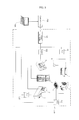
- FIG. 2 is a diagram illustrating a connection structure of facility devices installed in a point according to an exemplary embodiment of the present invention.
- a central server 1 or 200 is connected to a point controller 100.
- the central server 1 or 200 includes a terminal connecting with the central server 200 from the outside.
- a cooling/heating device such as an air conditioner, a cooler, or a heating cabinet controlling internal air and a security device are installed inside the one point 10.
- a plurality of power measuring devices 151 to 154 connected to facility devices, respectively, for measuring power consumption are provided.
- Indoor units 5, 7, and 8, an outdoor unit 6, a refrigerator 4, a show case 3, a heating cabinet 2, a calculator 1, and an illumination device 9 may be provided in the point.
- the indoor unit 5, 7, and 8 conditions indoor air, and may be simultaneously or independently operated according to an indoor air conditioning load.
- the air conditioner may include a unit such as a ventilation device, an air cleaner, a humidifier, and a dehumidifier as well as the indoor unit and the outdoor unit.
- a unit such as a ventilation device, an air cleaner, a humidifier, and a dehumidifier as well as the indoor unit and the outdoor unit.
- a following description will be made on the assumption that the indoor unit and the outdoor unit are installed by way of example.
- the number of indoor units and outdoor units is not limited.
- the indoor unit includes an indoor heat exchanger (not shown), an indoor fan (not shown), and an expansion valve (not shown) in which a supplied refrigerant is expanded, and a plurality of sensors (not shown).
- the outdoor unit includes a compressor (not shown) receiving a refrigerant and compressing, an outdoor heat exchanger (not shown) heat-exchanging the refrigerant with outdoor air, an accumulator (not shown) extracting gas refrigerant from the supplied refrigerant and providing the extracted gas refrigerant to the compressor, and a 4-way valve (not shown) selecting a flow passage of the refrigerant according to a heating operation.
- a least one illumination device 9 is provided, and is connected by a connected switch.
- the refrigerator 4 of the show case 3 is used to maintain the inside at a preset temperature and to have foods in one's custody.
- the show case 3 exposes cool air according to a cooling cycle to reduce an internal temperature.
- the heating cabinet 2 maintains the internal temperature greater than a predetermine temperature so that an internal object maintains warm.
- the calculator manages money and issues a receipt.
- a facility device installed in the point manages operation state data by devices and power consumption information by devices through a point controller 100 in the point.
- the point controller 100 stores power consumption data measured and received from power measuring devices 151 to 154, and control data for each device and operation state data.
- the point controller 100 is connected to the central server 200, transceives data, changes control setting with respect to each device according to data received from the central server 200, and monitors an operation of the central server 200.
- a unique account is allocated to the point controller 100 by points so that an identification (ID) according to the account is issued.
- the point controller 100 may access the central server 200 through an ID serving as an account of a point to receive control data with respect to a corresponding point and a control recording.
- the point controller 100 transmits collected and stored power consumption information by points to the central server 200 and receives corresponding fee information.
- the central server 1 or 200 may identify respective points using accounts allocated to the points and transmit requested data. Each point controller may connect with the central server using the allocated account, and request point data to the central server.
- IDs whose authority is different are allocated to the central server and each point.
- data are restrictively displayed according to authority set to an ID.
- the point controller 100 receives only data with respect to a corresponding point from the central server 200.
- the central server 200 may integrally or independently control a plurality of points according to setting, and may exceptionally process a predetermined point during integral control.
- the central server 200 may provide data regarding a predetermined point according to a connection account with respect to connection of a terminal 300 such as a portable terminal or a notebook computer. In this case, the central server 200 transmits data of a point corresponding to a connection account regardless of a type of a connected terminal.
- FIG. 3 is a block diagram illustrating a configuration of a point controller according to an exemplary embodiment of the present invention.
- a point controller 100 provided in each point includes an illumination controller 190, an air conditioner controller 170, a show case controller 180, a data part 120, a communication unit 160, an input part 140, an output part 130, and a controller 110 controlling an overall operation of the point controller 100.
- a power measuring device 150 is connected to the controller 110.
- the input part 140 includes at least one button and switch, receives a control command with respect to each facility device, and provides the received control command to the controller 110.
- the output part 130 outputs data with respect to an operation state of each facility device, outputs a control interface with respect to each facility device in a point, and outputs a specific effect sound or alarm sound in some cases.
- the output unit 130 outputs point data received from the central server 200 on a screen.
- Control data 121 for controlling operations of an air conditioner, an illumination device, and a show case, and power data 122 by devices with respect to a power consumption amount measured from the power measuring devices 151 to 154 are stored in the data part 120.
- Information for calculating fees and fee data 123 received from the central server 200 is stored.
- the controller 110 generates a control command with respect to an air conditioner, an illumination device, and a show case in response to a command inputted through the input unit 140 or a command received from the central server 200 through the communication unit 160, and provides the generated control command to an air conditioner controller, an illumination controller, and a show case controller.
- the controller 110 receives a power consumption amount from the power measuring device 150 (151 to 154) to analyze the power consumption amount of each device, and collects information with respect to an operation state of each device.
- the controller 110 is connected to a gateway for receiving data with the power measuring device 150 (151 to 154) or the gateway is mounted in the controller 110 and collects information with respect to a power consumption amount.
- the controller 110 transmits operation information of a device and power consumption information to the central server 200 through the communication part 160.
- the controller 110 may receive an internal temperature, an external temperature, and a humidity of the point measured by a plurality of sensors (not shown).
- the controller 110 may control devices according to power consumption by devices.
- the controller 110 controls an operation of each device according thereto.
- the air conditioner controller 170 controls an operations of an outdoor unit 6, indoor units 5, 7, and 8, and a ventilation device according to a control command of the controller 110.
- the air conditioner controller 170 controls a compressor to operate according to setting of an indoor unit and controls an operation frequency of the compressor to control an operation of an outdoor unit, so that cool air is discharged into an interior of a room.
- the air conditioner controller 170 controls an operation of a ventilation device according to a pollution level of indoor air, and controls the ventilation device to operation in conjunction with an operation of an indoor unit.
- the illumination controller 130 controls brightnenss of each illumination device according to switch input and a control command of the controller 110.
- the show case controller 180 controls temperatures of the show case 3, the refrigerator 4, and the heating cabinet 2 according to setting, and controls corresponding cooling or heating cycles.
- the central server 200 controls provision of data when a point controller 100, a central server or a portable terminal and an external terminal of each point connect and processes input data.
- the central server 200 performs authentication with respect to an accessed ID, and controls such that data corresponding to authority allocated to an ID is transmitted according to an authentication result.
- the central server 200 computes fee information with respect to each point based on power amount information by points received from the point controller 100 and fee calculation information according to an input of the point controller 100.
- the fee calculation information by points is different from each other, different fees may be computed even in the points having the same power consumption.
- the central server 200 computes a pattern, a cumulative amount, and a statistic value with power consumption of each point and statistic data with respect to a fee and transmit them to the point controller 100.
- the central server 200 transmits power information and fee information of at least one of day, week, month, year, and a designated period in response to a request from the point controller or a terminal.
- the central server 200 computes and transmits information regarding a power consumption amount, an expected used amount, a cumulative used amount, and a target used amount with respect to one point.
- the central server 200 may compute power information and fee information in consideration of importance of a facility device with respect to power consumption of a point.
- a point controller accumulates respective individual power information with respect to a facility device such as an air conditioner, an illumination device, and an electric device according to power amount information received from a plurality of power measuring devices, and periodically transmits the accumulated individual power information.
- FIG. 4 is a flowchart illustrating a control method of a point controller according to an exemplary embodiment of the present invention.
- power consumption amounts with respect to respective facility devices are measured by a plurality of power measuring devices 150 (151 to 154), a controller 110 of a point controller 100 receives the power consumption amounts from the measuring devices 151 to 154 (S310).
- the controller 100 collects data regarding the power consumption amounts inputted from the power measuring devices as data of respective facility devices, and stores the data in a data part 120 (S320).
- the controller 110 of a point controller transmits data stored in the data part 120 to a central server 200 (S330).
- the controller 100 of a point controller connects with the central server 200 through a communication unit 160 (S340).
- the controller 110 receives input account information, and receives data with respect to a point from the central server, particularly, power consumption information and fee data, and displays the data and the information (S350).
- FIG. 5 is a flowchart illustrating information collecting and operation method of a central server according to an exemplary embodiment of the present invention.
- a central server 200 receives power consumption data by points (S410), classifies and accumulatively stores the power consumption data by points (S420).
- received data are information regarding a power consumption amount in each point.
- the central server 200 computes fee information corresponding to collected power amount information (S430).
- the central server 200 computes different fees by points with respect to a power amount corresponding to fee calculation information received by points. That is, when fee calculation information of a point is different even if a power amount is equally consumed, the fee is changed.
- the central server 200 computes statistic data regarding power amount information and fee information with respect to data stored by points, namely, with respect to day, week, month, year, or a designated period.
- the central server 200 transmits data of a point corresponding to a connection account to a corresponding point controller or terminal according to a request from the point controller or the terminal (S440).
- the central server 200 may periodically transmit point data to the point controller.
- FIG. 6 is an exemplary diagram illustrating an example of a data input screen of a point controller through connecting the central server.
- a point controller may access a center server to receive power information with respect to a point or fee calculation information.
- the central server 200 transmits data of a corresponding point to a controller according to an authority set to the point account (131).
- the controller of a point controller transmits power amount information with respect to respective facility devices inputted from a plurality of power amount measuring devices to the central server 200.
- the central server 200 may confirm capacity information with respect to a point, information about a currently installed facility, energy management information, facility meter information, A/S management information, and information with respect to a report and setting (132).
- a show chase operation and a power used fee may be set through a setting menu (134).
- a point controller inputs fee calculation information of a current point through connecting the central server.
- the fee calculation information may include application of power use, contract power or fee application power, presence of invalid power meter, power factor, and receiving voltage information.
- the fee calculation information is used to compute fee information of the central server.
- FIG. 7 is an exemplary diagram illustrating an example of a data screen by points provided through connecting the central server.
- a point 10 connects with a central server 200 with a point account through a point controller or a terminal 90 (301)
- the central server 200 transmits data of a corresponding point to a controller according to authority set to a point account.
- the central server 200 may confirm capacity information with respect to a point, information about a currently installed facility, energy management information, facility meter information, A/S management information, and information with respect to a report and setting (132).
- an expected month used amount is displayed on a screen of an output part 130 (137).
- a user may confirm an energy reduce rate compared with a month target as an image, and information is displayed so that a consumption pattern for one month may be confirmed.
- power consumption information with respect to respective facility device may be confirmed.
- Each point controller may manage energy consumption while changing or maintaining operation setting with respect to facility devices in the point through this. Setting of the information is changed so that information accumulated in units of days, weeks, months, and years may be confirmed.
- the point controller collects and continuously transmits information about power amounts to the central server, the central server having received data with respect to a plurality of points provides power amount information with respect to each point and fee information according thereto, particularly, statistic data about power consumption and fees.
- each point can analyze power consumption pattern and fees of the point and easily set and control a facility device, individual power control according to the point is possible, thereby controlling power consumption conveniently and efficiently.
- the present invention relates a system and a method for controlling an air conditioner.
- power used information is collected by points and corresponding fee information is computed so that respective points can be managed, statistic data with respect to power amount information and fee information are transmitted to respective point so that a user read the information, thereby managing the information in the center or by points easily, and improving convenience.
Landscapes
- Engineering & Computer Science (AREA)
- Chemical & Material Sciences (AREA)
- Combustion & Propulsion (AREA)
- Mechanical Engineering (AREA)
- General Engineering & Computer Science (AREA)
- Human Computer Interaction (AREA)
- Signal Processing (AREA)
- Physics & Mathematics (AREA)
- Power Engineering (AREA)
- Fuzzy Systems (AREA)
- Mathematical Physics (AREA)
- Medical Informatics (AREA)
- Software Systems (AREA)
- Evolutionary Computation (AREA)
- General Physics & Mathematics (AREA)
- Automation & Control Theory (AREA)
- Computer Vision & Pattern Recognition (AREA)
- Artificial Intelligence (AREA)
- Health & Medical Sciences (AREA)
- Air Conditioning Control Device (AREA)
Applications Claiming Priority (1)
| Application Number | Priority Date | Filing Date | Title |
|---|---|---|---|
| KR1020120041076A KR101994695B1 (ko) | 2012-04-19 | 2012-04-19 | 공기조화기 제어시스템 및 그 방법 |
Publications (3)
| Publication Number | Publication Date |
|---|---|
| EP2653796A2 true EP2653796A2 (de) | 2013-10-23 |
| EP2653796A3 EP2653796A3 (de) | 2016-10-12 |
| EP2653796B1 EP2653796B1 (de) | 2020-08-12 |
Family
ID=48142664
Family Applications (1)
| Application Number | Title | Priority Date | Filing Date |
|---|---|---|---|
| EP13164337.1A Not-in-force EP2653796B1 (de) | 2012-04-19 | 2013-04-18 | System und Verfahren zum Steuern von mehreren Stellen, jeweils mit einer Klimaanlage, einer Beleuchtungseinrichtung und einem elektrischen Gerät |
Country Status (3)
| Country | Link |
|---|---|
| US (1) | US9389599B2 (de) |
| EP (1) | EP2653796B1 (de) |
| KR (1) | KR101994695B1 (de) |
Families Citing this family (7)
| Publication number | Priority date | Publication date | Assignee | Title |
|---|---|---|---|---|
| FR2976654B1 (fr) * | 2011-06-15 | 2013-07-12 | Voltalis | Dispositif de chauffage, ventilation et/ou climatisation a gestion d'alimentation ciblee. |
| JP2015226081A (ja) * | 2014-05-26 | 2015-12-14 | Necプラットフォームズ株式会社 | 制御装置、通信システム、制御方法およびプログラム |
| KR101921537B1 (ko) * | 2016-03-15 | 2018-11-23 | 엘지전자 주식회사 | 공기조화기 시스템 |
| KR101986753B1 (ko) * | 2017-09-20 | 2019-06-10 | (주)다산지앤지 | 공동 주택 자동 온도 조절 시스템 |
| KR102560460B1 (ko) * | 2019-01-16 | 2023-07-26 | 엘지전자 주식회사 | 공기조화기 및 이를 포함하는 공기조화시스템 |
| JP7085522B2 (ja) * | 2019-09-30 | 2022-06-16 | ダイキン工業株式会社 | 空気調和システム |
| CA3223092A1 (en) | 2021-06-17 | 2022-12-22 | John Bloemer | Whole building air quality control system |
Family Cites Families (24)
| Publication number | Priority date | Publication date | Assignee | Title |
|---|---|---|---|---|
| JP3680146B2 (ja) * | 2000-04-03 | 2005-08-10 | ダイキン工業株式会社 | 施設運用方法 |
| US7039532B2 (en) * | 2001-06-28 | 2006-05-02 | Hunter Robert R | Method and apparatus for reading and controlling utility consumption |
| KR20040032653A (ko) * | 2002-10-10 | 2004-04-17 | 엘지전자 주식회사 | 전력분배형 멀티 공기조화기 시스템 및 그 동작방법 |
| EP1489719A3 (de) * | 2003-06-20 | 2007-05-02 | Matsushita Electric Industrial Co., Ltd. | Energievewaltungssystem, Energieverwaltungsverfahren und Einheit zur Verfügungsstellung von Informationen über energiesparende empfohlene Einrichtung |
| US7774245B2 (en) * | 2006-11-16 | 2010-08-10 | Genea Energy Partners, Inc. | Building optimization platform and web-based invoicing system |
| KR20090067740A (ko) | 2007-12-21 | 2009-06-25 | 엘지전자 주식회사 | 공기조화장치의 전력분배시스템 |
| US20090187499A1 (en) * | 2008-01-21 | 2009-07-23 | David Mulder | System, Method and Computer Program Product for Providing Demand Response Functionality |
| US8255090B2 (en) * | 2008-02-01 | 2012-08-28 | Energyhub | System and method for home energy monitor and control |
| US8170886B2 (en) * | 2008-03-28 | 2012-05-01 | The Nielsen Company (U.S.), Llc | Systems, methods, and apparatus to generate an energy consumption index |
| US20090302996A1 (en) * | 2008-06-10 | 2009-12-10 | Millennial Net, Inc. | System and method for a management server |
| US20090302994A1 (en) * | 2008-06-10 | 2009-12-10 | Mellennial Net, Inc. | System and method for energy management |
| US8200370B2 (en) * | 2008-12-04 | 2012-06-12 | American Power Conversion Corporation | Energy reduction |
| US20100211509A1 (en) * | 2009-02-17 | 2010-08-19 | Jacobs Richard B | Resource monitoring device |
| US20100217550A1 (en) * | 2009-02-26 | 2010-08-26 | Jason Crabtree | System and method for electric grid utilization and optimization |
| US8816870B2 (en) * | 2009-03-31 | 2014-08-26 | Pvt Solar, Inc. | Healthy home graphical user interface method and device |
| WO2010135372A1 (en) * | 2009-05-18 | 2010-11-25 | Alarm.Com Incorporated | Remote device control and energy monitoring |
| US20110112780A1 (en) * | 2009-11-06 | 2011-05-12 | David Moss | Electrical power consumption measuring system |
| US8321188B2 (en) * | 2009-11-18 | 2012-11-27 | Bank Of America Corporation | Weather-related energy-usage analysis |
| EP2511716B1 (de) * | 2009-12-02 | 2016-04-27 | Nec Corporation | Leistungsmesssystem, leistungsmessverfahren und informationsverarbeitungsvorrichtung |
| JP2011142753A (ja) | 2010-01-07 | 2011-07-21 | Panasonic Corp | 家電機器制御装置及び家電機器制御システム |
| US9310792B2 (en) * | 2010-05-03 | 2016-04-12 | Battelle Memorial Institute | Scheduling and modeling the operation of controllable and non-controllable electronic devices |
| US8290628B2 (en) * | 2010-07-23 | 2012-10-16 | Lg Electronics Inc. | Air conditioner and method for controlling the same |
| US20120065791A1 (en) * | 2010-09-28 | 2012-03-15 | General Electric Company | Home energy manager for providing energy projections |
| US20120215464A1 (en) * | 2011-02-18 | 2012-08-23 | Utilivista Limited | Energy consumption monitor |
-
2012
- 2012-04-19 KR KR1020120041076A patent/KR101994695B1/ko not_active Expired - Fee Related
-
2013
- 2013-04-18 US US13/865,372 patent/US9389599B2/en not_active Expired - Fee Related
- 2013-04-18 EP EP13164337.1A patent/EP2653796B1/de not_active Not-in-force
Non-Patent Citations (1)
| Title |
|---|
| None |
Also Published As
| Publication number | Publication date |
|---|---|
| US20130304267A1 (en) | 2013-11-14 |
| EP2653796B1 (de) | 2020-08-12 |
| US9389599B2 (en) | 2016-07-12 |
| EP2653796A3 (de) | 2016-10-12 |
| KR101994695B1 (ko) | 2019-07-01 |
| KR20130118125A (ko) | 2013-10-29 |
Similar Documents
| Publication | Publication Date | Title |
|---|---|---|
| US9389599B2 (en) | System and method for controlling air conditioner | |
| JP4910020B2 (ja) | 需要家エネルギーマネジメントシステム | |
| JP6976976B2 (ja) | マルチレベルモデル予測制御のシステムと方法 | |
| EP3012546B1 (de) | Steuerungsvorrichtung für eine klimaanlage und steuerungsverfahren für eine klimaanlage | |
| CN106997194B (zh) | 用于监测和控制中央设施的系统以及方法 | |
| Lu et al. | Investigation of air management and energy performance in a data center in Finland: Case study | |
| US20080234869A1 (en) | Remote Performance Monitor and Remote Performance Monitoring Method | |
| CN101539321A (zh) | 应用于空调设备的电力控制系统 | |
| JP6009586B2 (ja) | 空気調和制御システム | |
| US20080142607A1 (en) | Air conditioning system and method of controlling the same | |
| JP6937261B2 (ja) | 空調制御装置、空調制御方法及びコンピュータプログラム | |
| JP2009115392A (ja) | 省エネルギー制御システム | |
| US9366466B2 (en) | Air conditioner and method for controlling the same | |
| US20110218681A1 (en) | Air conditioning system and method of controlling the same | |
| KR100751834B1 (ko) | 히트펌프식 냉난방 장치의 통합제어 시스템 | |
| JP5473619B2 (ja) | 空気調和機の制御装置 | |
| JP2010038471A (ja) | 空調機管理装置及び空調機管理方法 | |
| KR102032811B1 (ko) | 냉동기의 제거열량을 이용한 에너지소비 절감 장치 및 방법 | |
| KR20190029368A (ko) | 공기조화기 | |
| JP2006097941A (ja) | 空気調和機の管理システム | |
| JP5395536B2 (ja) | 省エネルギー効果量算出装置および方法 | |
| JP5100723B2 (ja) | 消費電力量監視装置および消費電力量監視方法 | |
| WO2017199298A1 (ja) | 空気調和システム | |
| KR102117597B1 (ko) | 공기조화기 및 그 동작방법 | |
| KR20180011672A (ko) | 공기조화기 시스템 및 그 방법 |
Legal Events
| Date | Code | Title | Description |
|---|---|---|---|
| PUAI | Public reference made under article 153(3) epc to a published international application that has entered the european phase |
Free format text: ORIGINAL CODE: 0009012 |
|
| 17P | Request for examination filed |
Effective date: 20130515 |
|
| AK | Designated contracting states |
Kind code of ref document: A2 Designated state(s): AL AT BE BG CH CY CZ DE DK EE ES FI FR GB GR HR HU IE IS IT LI LT LU LV MC MK MT NL NO PL PT RO RS SE SI SK SM TR |
|
| AX | Request for extension of the european patent |
Extension state: BA ME |
|
| PUAL | Search report despatched |
Free format text: ORIGINAL CODE: 0009013 |
|
| AK | Designated contracting states |
Kind code of ref document: A3 Designated state(s): AL AT BE BG CH CY CZ DE DK EE ES FI FR GB GR HR HU IE IS IT LI LT LU LV MC MK MT NL NO PL PT RO RS SE SI SK SM TR |
|
| AX | Request for extension of the european patent |
Extension state: BA ME |
|
| RIC1 | Information provided on ipc code assigned before grant |
Ipc: F24F 11/00 20060101AFI20160907BHEP |
|
| RBV | Designated contracting states (corrected) |
Designated state(s): AL AT BE BG CH CY CZ DE DK EE ES FI FR GB GR HR HU IE IS IT LI LT LU LV MC MK MT NL NO PL PT RO RS SE SI SK SM TR |
|
| STAA | Information on the status of an ep patent application or granted ep patent |
Free format text: STATUS: EXAMINATION IS IN PROGRESS |
|
| 17Q | First examination report despatched |
Effective date: 20170524 |
|
| RIC1 | Information provided on ipc code assigned before grant |
Ipc: F24F 11/30 20180101ALI20200123BHEP Ipc: H02J 3/14 20060101ALI20200123BHEP Ipc: F24F 11/00 20180101AFI20200123BHEP Ipc: F24F 11/62 20180101ALI20200123BHEP Ipc: H02J 13/00 20060101ALI20200123BHEP |
|
| GRAP | Despatch of communication of intention to grant a patent |
Free format text: ORIGINAL CODE: EPIDOSNIGR1 |
|
| STAA | Information on the status of an ep patent application or granted ep patent |
Free format text: STATUS: GRANT OF PATENT IS INTENDED |
|
| INTG | Intention to grant announced |
Effective date: 20200311 |
|
| GRAS | Grant fee paid |
Free format text: ORIGINAL CODE: EPIDOSNIGR3 |
|
| GRAA | (expected) grant |
Free format text: ORIGINAL CODE: 0009210 |
|
| STAA | Information on the status of an ep patent application or granted ep patent |
Free format text: STATUS: THE PATENT HAS BEEN GRANTED |
|
| AK | Designated contracting states |
Kind code of ref document: B1 Designated state(s): AL AT BE BG CH CY CZ DE DK EE ES FI FR GB GR HR HU IE IS IT LI LT LU LV MC MK MT NL NO PL PT RO RS SE SI SK SM TR |
|
| REG | Reference to a national code |
Ref country code: CH Ref legal event code: EP |
|
| REG | Reference to a national code |
Ref country code: DE Ref legal event code: R096 Ref document number: 602013071507 Country of ref document: DE |
|
| REG | Reference to a national code |
Ref country code: IE Ref legal event code: FG4D |
|
| REG | Reference to a national code |
Ref country code: AT Ref legal event code: REF Ref document number: 1301923 Country of ref document: AT Kind code of ref document: T Effective date: 20200915 |
|
| REG | Reference to a national code |
Ref country code: LT Ref legal event code: MG4D |
|
| REG | Reference to a national code |
Ref country code: NL Ref legal event code: MP Effective date: 20200812 |
|
| PG25 | Lapsed in a contracting state [announced via postgrant information from national office to epo] |
Ref country code: SE Free format text: LAPSE BECAUSE OF FAILURE TO SUBMIT A TRANSLATION OF THE DESCRIPTION OR TO PAY THE FEE WITHIN THE PRESCRIBED TIME-LIMIT Effective date: 20200812 Ref country code: BG Free format text: LAPSE BECAUSE OF FAILURE TO SUBMIT A TRANSLATION OF THE DESCRIPTION OR TO PAY THE FEE WITHIN THE PRESCRIBED TIME-LIMIT Effective date: 20201112 Ref country code: GR Free format text: LAPSE BECAUSE OF FAILURE TO SUBMIT A TRANSLATION OF THE DESCRIPTION OR TO PAY THE FEE WITHIN THE PRESCRIBED TIME-LIMIT Effective date: 20201113 Ref country code: LT Free format text: LAPSE BECAUSE OF FAILURE TO SUBMIT A TRANSLATION OF THE DESCRIPTION OR TO PAY THE FEE WITHIN THE PRESCRIBED TIME-LIMIT Effective date: 20200812 Ref country code: ES Free format text: LAPSE BECAUSE OF FAILURE TO SUBMIT A TRANSLATION OF THE DESCRIPTION OR TO PAY THE FEE WITHIN THE PRESCRIBED TIME-LIMIT Effective date: 20200812 Ref country code: NO Free format text: LAPSE BECAUSE OF FAILURE TO SUBMIT A TRANSLATION OF THE DESCRIPTION OR TO PAY THE FEE WITHIN THE PRESCRIBED TIME-LIMIT Effective date: 20201112 Ref country code: FI Free format text: LAPSE BECAUSE OF FAILURE TO SUBMIT A TRANSLATION OF THE DESCRIPTION OR TO PAY THE FEE WITHIN THE PRESCRIBED TIME-LIMIT Effective date: 20200812 Ref country code: HR Free format text: LAPSE BECAUSE OF FAILURE TO SUBMIT A TRANSLATION OF THE DESCRIPTION OR TO PAY THE FEE WITHIN THE PRESCRIBED TIME-LIMIT Effective date: 20200812 |
|
| REG | Reference to a national code |
Ref country code: AT Ref legal event code: MK05 Ref document number: 1301923 Country of ref document: AT Kind code of ref document: T Effective date: 20200812 |
|
| PG25 | Lapsed in a contracting state [announced via postgrant information from national office to epo] |
Ref country code: RS Free format text: LAPSE BECAUSE OF FAILURE TO SUBMIT A TRANSLATION OF THE DESCRIPTION OR TO PAY THE FEE WITHIN THE PRESCRIBED TIME-LIMIT Effective date: 20200812 Ref country code: PL Free format text: LAPSE BECAUSE OF FAILURE TO SUBMIT A TRANSLATION OF THE DESCRIPTION OR TO PAY THE FEE WITHIN THE PRESCRIBED TIME-LIMIT Effective date: 20200812 Ref country code: LV Free format text: LAPSE BECAUSE OF FAILURE TO SUBMIT A TRANSLATION OF THE DESCRIPTION OR TO PAY THE FEE WITHIN THE PRESCRIBED TIME-LIMIT Effective date: 20200812 Ref country code: NL Free format text: LAPSE BECAUSE OF FAILURE TO SUBMIT A TRANSLATION OF THE DESCRIPTION OR TO PAY THE FEE WITHIN THE PRESCRIBED TIME-LIMIT Effective date: 20200812 Ref country code: IS Free format text: LAPSE BECAUSE OF FAILURE TO SUBMIT A TRANSLATION OF THE DESCRIPTION OR TO PAY THE FEE WITHIN THE PRESCRIBED TIME-LIMIT Effective date: 20201212 |
|
| PG25 | Lapsed in a contracting state [announced via postgrant information from national office to epo] |
Ref country code: CZ Free format text: LAPSE BECAUSE OF FAILURE TO SUBMIT A TRANSLATION OF THE DESCRIPTION OR TO PAY THE FEE WITHIN THE PRESCRIBED TIME-LIMIT Effective date: 20200812 Ref country code: EE Free format text: LAPSE BECAUSE OF FAILURE TO SUBMIT A TRANSLATION OF THE DESCRIPTION OR TO PAY THE FEE WITHIN THE PRESCRIBED TIME-LIMIT Effective date: 20200812 Ref country code: DK Free format text: LAPSE BECAUSE OF FAILURE TO SUBMIT A TRANSLATION OF THE DESCRIPTION OR TO PAY THE FEE WITHIN THE PRESCRIBED TIME-LIMIT Effective date: 20200812 Ref country code: SM Free format text: LAPSE BECAUSE OF FAILURE TO SUBMIT A TRANSLATION OF THE DESCRIPTION OR TO PAY THE FEE WITHIN THE PRESCRIBED TIME-LIMIT Effective date: 20200812 Ref country code: RO Free format text: LAPSE BECAUSE OF FAILURE TO SUBMIT A TRANSLATION OF THE DESCRIPTION OR TO PAY THE FEE WITHIN THE PRESCRIBED TIME-LIMIT Effective date: 20200812 |
|
| REG | Reference to a national code |
Ref country code: DE Ref legal event code: R097 Ref document number: 602013071507 Country of ref document: DE |
|
| PG25 | Lapsed in a contracting state [announced via postgrant information from national office to epo] |
Ref country code: AT Free format text: LAPSE BECAUSE OF FAILURE TO SUBMIT A TRANSLATION OF THE DESCRIPTION OR TO PAY THE FEE WITHIN THE PRESCRIBED TIME-LIMIT Effective date: 20200812 Ref country code: AL Free format text: LAPSE BECAUSE OF FAILURE TO SUBMIT A TRANSLATION OF THE DESCRIPTION OR TO PAY THE FEE WITHIN THE PRESCRIBED TIME-LIMIT Effective date: 20200812 |
|
| PLBE | No opposition filed within time limit |
Free format text: ORIGINAL CODE: 0009261 |
|
| STAA | Information on the status of an ep patent application or granted ep patent |
Free format text: STATUS: NO OPPOSITION FILED WITHIN TIME LIMIT |
|
| PG25 | Lapsed in a contracting state [announced via postgrant information from national office to epo] |
Ref country code: SK Free format text: LAPSE BECAUSE OF FAILURE TO SUBMIT A TRANSLATION OF THE DESCRIPTION OR TO PAY THE FEE WITHIN THE PRESCRIBED TIME-LIMIT Effective date: 20200812 |
|
| 26N | No opposition filed |
Effective date: 20210514 |
|
| PG25 | Lapsed in a contracting state [announced via postgrant information from national office to epo] |
Ref country code: IT Free format text: LAPSE BECAUSE OF FAILURE TO SUBMIT A TRANSLATION OF THE DESCRIPTION OR TO PAY THE FEE WITHIN THE PRESCRIBED TIME-LIMIT Effective date: 20200812 |
|
| PG25 | Lapsed in a contracting state [announced via postgrant information from national office to epo] |
Ref country code: SI Free format text: LAPSE BECAUSE OF FAILURE TO SUBMIT A TRANSLATION OF THE DESCRIPTION OR TO PAY THE FEE WITHIN THE PRESCRIBED TIME-LIMIT Effective date: 20200812 |
|
| PG25 | Lapsed in a contracting state [announced via postgrant information from national office to epo] |
Ref country code: MC Free format text: LAPSE BECAUSE OF FAILURE TO SUBMIT A TRANSLATION OF THE DESCRIPTION OR TO PAY THE FEE WITHIN THE PRESCRIBED TIME-LIMIT Effective date: 20200812 |
|
| GBPC | Gb: european patent ceased through non-payment of renewal fee |
Effective date: 20210418 |
|
| PG25 | Lapsed in a contracting state [announced via postgrant information from national office to epo] |
Ref country code: LU Free format text: LAPSE BECAUSE OF NON-PAYMENT OF DUE FEES Effective date: 20210418 |
|
| REG | Reference to a national code |
Ref country code: BE Ref legal event code: MM Effective date: 20210430 |
|
| PG25 | Lapsed in a contracting state [announced via postgrant information from national office to epo] |
Ref country code: FR Free format text: LAPSE BECAUSE OF NON-PAYMENT OF DUE FEES Effective date: 20210430 Ref country code: GB Free format text: LAPSE BECAUSE OF NON-PAYMENT OF DUE FEES Effective date: 20210418 Ref country code: CH Free format text: LAPSE BECAUSE OF NON-PAYMENT OF DUE FEES Effective date: 20210430 Ref country code: LI Free format text: LAPSE BECAUSE OF NON-PAYMENT OF DUE FEES Effective date: 20210430 |
|
| PG25 | Lapsed in a contracting state [announced via postgrant information from national office to epo] |
Ref country code: IE Free format text: LAPSE BECAUSE OF NON-PAYMENT OF DUE FEES Effective date: 20210418 |
|
| PG25 | Lapsed in a contracting state [announced via postgrant information from national office to epo] |
Ref country code: IS Free format text: LAPSE BECAUSE OF FAILURE TO SUBMIT A TRANSLATION OF THE DESCRIPTION OR TO PAY THE FEE WITHIN THE PRESCRIBED TIME-LIMIT Effective date: 20201212 |
|
| PG25 | Lapsed in a contracting state [announced via postgrant information from national office to epo] |
Ref country code: BE Free format text: LAPSE BECAUSE OF NON-PAYMENT OF DUE FEES Effective date: 20210430 |
|
| PG25 | Lapsed in a contracting state [announced via postgrant information from national office to epo] |
Ref country code: PT Free format text: LAPSE BECAUSE OF FAILURE TO SUBMIT A TRANSLATION OF THE DESCRIPTION OR TO PAY THE FEE WITHIN THE PRESCRIBED TIME-LIMIT Effective date: 20201214 |
|
| PG25 | Lapsed in a contracting state [announced via postgrant information from national office to epo] |
Ref country code: HU Free format text: LAPSE BECAUSE OF FAILURE TO SUBMIT A TRANSLATION OF THE DESCRIPTION OR TO PAY THE FEE WITHIN THE PRESCRIBED TIME-LIMIT; INVALID AB INITIO Effective date: 20130418 |
|
| PG25 | Lapsed in a contracting state [announced via postgrant information from national office to epo] |
Ref country code: CY Free format text: LAPSE BECAUSE OF FAILURE TO SUBMIT A TRANSLATION OF THE DESCRIPTION OR TO PAY THE FEE WITHIN THE PRESCRIBED TIME-LIMIT Effective date: 20200812 |
|
| PGFP | Annual fee paid to national office [announced via postgrant information from national office to epo] |
Ref country code: DE Payment date: 20230306 Year of fee payment: 11 |
|
| PG25 | Lapsed in a contracting state [announced via postgrant information from national office to epo] |
Ref country code: MK Free format text: LAPSE BECAUSE OF FAILURE TO SUBMIT A TRANSLATION OF THE DESCRIPTION OR TO PAY THE FEE WITHIN THE PRESCRIBED TIME-LIMIT Effective date: 20200812 |
|
| PG25 | Lapsed in a contracting state [announced via postgrant information from national office to epo] |
Ref country code: TR Free format text: LAPSE BECAUSE OF FAILURE TO SUBMIT A TRANSLATION OF THE DESCRIPTION OR TO PAY THE FEE WITHIN THE PRESCRIBED TIME-LIMIT Effective date: 20200812 |
|
| PG25 | Lapsed in a contracting state [announced via postgrant information from national office to epo] |
Ref country code: MT Free format text: LAPSE BECAUSE OF FAILURE TO SUBMIT A TRANSLATION OF THE DESCRIPTION OR TO PAY THE FEE WITHIN THE PRESCRIBED TIME-LIMIT Effective date: 20200812 |
|
| REG | Reference to a national code |
Ref country code: DE Ref legal event code: R119 Ref document number: 602013071507 Country of ref document: DE |
|
| PG25 | Lapsed in a contracting state [announced via postgrant information from national office to epo] |
Ref country code: DE Free format text: LAPSE BECAUSE OF NON-PAYMENT OF DUE FEES Effective date: 20241105 |
|
| PG25 | Lapsed in a contracting state [announced via postgrant information from national office to epo] |
Ref country code: DE Free format text: LAPSE BECAUSE OF NON-PAYMENT OF DUE FEES Effective date: 20241105 |