EP2653881A1 - Localisation coopérative de dispositifs électroniques portables - Google Patents
Localisation coopérative de dispositifs électroniques portables Download PDFInfo
- Publication number
- EP2653881A1 EP2653881A1 EP12164887.7A EP12164887A EP2653881A1 EP 2653881 A1 EP2653881 A1 EP 2653881A1 EP 12164887 A EP12164887 A EP 12164887A EP 2653881 A1 EP2653881 A1 EP 2653881A1
- Authority
- EP
- European Patent Office
- Prior art keywords
- portable electronic
- location
- electronic device
- transmitter
- query
- Prior art date
- Legal status (The legal status is an assumption and is not a legal conclusion. Google has not performed a legal analysis and makes no representation as to the accuracy of the status listed.)
- Granted
Links
Images




Classifications
-
- G—PHYSICS
- G01—MEASURING; TESTING
- G01S—RADIO DIRECTION-FINDING; RADIO NAVIGATION; DETERMINING DISTANCE OR VELOCITY BY USE OF RADIO WAVES; LOCATING OR PRESENCE-DETECTING BY USE OF THE REFLECTION OR RERADIATION OF RADIO WAVES; ANALOGOUS ARRANGEMENTS USING OTHER WAVES
- G01S5/00—Position-fixing by co-ordinating two or more direction or position line determinations; Position-fixing by co-ordinating two or more distance determinations
- G01S5/0009—Transmission of position information to remote stations
-
- G—PHYSICS
- G01—MEASURING; TESTING
- G01S—RADIO DIRECTION-FINDING; RADIO NAVIGATION; DETERMINING DISTANCE OR VELOCITY BY USE OF RADIO WAVES; LOCATING OR PRESENCE-DETECTING BY USE OF THE REFLECTION OR RERADIATION OF RADIO WAVES; ANALOGOUS ARRANGEMENTS USING OTHER WAVES
- G01S5/00—Position-fixing by co-ordinating two or more direction or position line determinations; Position-fixing by co-ordinating two or more distance determinations
- G01S5/02—Position-fixing by co-ordinating two or more direction or position line determinations; Position-fixing by co-ordinating two or more distance determinations using radio waves
- G01S5/0269—Inferred or constrained positioning, e.g. employing knowledge of the physical or electromagnetic environment, state of motion or other contextual information to infer or constrain a position
Definitions
- the current description relates to an apparatus, system and methods of determining a location of a portable electronic device, and in particular to determining a position of a portable electronic device using cooperative localization.
- GPS Global Positioning System
- GNSS Global Navigation Satellite System
- Positioning services are often unavailable indoors, or in areas of poor GNSS signal reception.
- the user has to be localized via other such as assisted GPS systems that use cellular or Wi-Fi radio signal strength indicator (RSSI) measurements to provide positioning information, Wi-Fi signature analysis or radio frequency beacon system.
- RSSI radio signal strength indicator
- a method of cooperative localization of a portable electronic device comprising receiving at a server a plurality of location identification messages each providing a known location information of a respective portable electronic device and an associated transmitter identification (ID) of the respective portable electronic device; storing the received location information and associated transmitter IDs at the server; receiving at the server a location request message providing one or more transmitter IDs in communication range with a query portable electronic device and a transmitter ID of the query portable electronic device; retrieving location information from the stored location information associated with the one or more transmitter IDs received in the location request message; estimating a location of the query portable electronic device based on the retrieved location information; storing the estimated location of the query portable electronic device with the associated transmitter ID; and transmitting the estimated location to the query portable electronic device.
- ID transmitter identification
- a computing device for estimating a location of a portable electronic device comprising: a processor for executing instructions; and a memory for storing instructions, the instructions when executed by the processor configuring the computing device to provide a method comprising: receiving at a server a plurality of location identification messages each providing a known location information of a respective portable electronic device and an associated transmitter identification (ID) of the respective portable electronic device; storing the received location information and associated transmitter IDs at the server; receiving at the server a location request message providing one or more transmitter IDs in communication range with a query portable electronic device and a transmitter ID of the query portable electronic device; retrieving location information from the stored location information associated with the one or more transmitter IDs received in the location request message; estimating a location of the query portable electronic device based on the retrieved location information; storing the estimated location of the query portable electronic device with the associated transmitter ID; and transmitting the estimated location to the query portable electronic device.
- a server a plurality of location identification messages each providing a known location information of a respective portable electronic device and
- a computer readable memory containing instructions for cooperative localization of a portable electronic device, the instruction which when executed by a processor performing: receiving at a server a plurality of location identification messages each providing a known location information of a respective portable electronic device and an associated transmitter identification (ID) of the respective portable electronic device; storing the received location information and associated transmitter IDs at the server; receiving at the server a location request message providing one or more transmitter IDs in communication range with a query portable electronic device and a transmitter ID of the query portable electronic device; retrieving location information from the stored location information associated with the one or more transmitter IDs received in the location request message; estimating a location of the query portable electronic device based on the retrieved location information; storing the estimated location of the query portable electronic device with the associated transmitter ID; and transmitting the estimated location to the query portable electronic device.
- Location based services require that the position of a user be known.
- the position of a user or device may be determined in various ways, such as through GPS or other means.
- Current location determination techniques typically do not work well indoors as they require the reception of GPS signals, or signals from wireless transmitters such as cell tower transmitters, which may not penetrate indoors well.
- the short-range communication radios are considered herein to be Bluetooth TM radios although other short-range communication radios are possible such as ZigBeeTM.
- the communications may utilize a peer-to-peer communication technologies or Wireless Personal Area Network (WPAN) standards.
- the location technique described further herein determines a location estimate for a portable electronic device based on locations associated with Bluetooth radios that are in communication range of the portable electronic device.
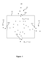
- FIG. 1 depicts an illustrative environment in which the cooperative localization can be used.
- the environment 100 comprises an indoor location 102.
- the indoor location 102 may comprise a public space such as a shopping mall, museum, building, etc.
- the cooperative localization described herein can be used to provide a location of users, or more particularly the portable electronic devices' of the users, within the public space 102.
- the user locations determined using the cooperative localization technique described herein can be used for various purposes, such as providing directions from a user's current location to a desired location within the public space 102.
- the location estimate may be further used to provide additional information to the user based on the location estimate such as information pertaining to a display of the user's estimated location, a map, directions, or to push or provide information relevant to the users location for example a special offer associated with a product sold at the estimated location of the user.
- a plurality of users 104 may be outside the indoor location 102. While outdoors, the users 104 may be able to receive a GPS signal and as such be able to determine the position of the user with a reasonably high degree of accuracy, represented graphically in Figure by the black circles.
- the users 104 may enter the indoor location 102 through one of a plurality of doors 106a, 106b, 106c, 106d. As depicted in Figure 1 , once inside the indoor location 102, the users no longer receive the GPS signal and as such cannot use GPS to determine their location as represented by the white circles 108.
- the location of the indoor users' 108 can be determined based on the location of adjacent users, or users within short-range communication range such as Bluetooth.
- the user's portable electronic device can utilize inertial navigation to 'pull' the GPS location into the indoor space 102. That is, the inertial navigation of the portable electronic device can be used to extend the GPS location into the indoor space 102, providing known location information inside the indoor space 102.
- the portable electronic devices can continue to use inertial navigation to further extend the range of known locations further into the indoor space 102.
- FIG. 2 depicts an illustrative technique of determining a location of a portable electronic device based on a location of adjacent portable electronic devices.
- Each of the portable electronic devices 202a, 202b, 202c include a Bluetooth radio that transmits a Bluetooth signal 204a, 204b, 204c that can be received at the portable electronic device 206 for which the location is being estimated.
- the signal strength of the Bluetooth signals received at the portable electronic device 206 depends upon the distance to the other portable electronic devices 202a, 202b, 202c.
- the signal strength is represented graphically in Figure 2 using the width of the broken lines 204a, 204b, 204c, that is the thicker the line, the higher the received signal strength.
- the locations of the other portable electronic devices 202a, 202b, 202c can be determined, for example using the Bluetooth radio identifier of the portable electronic devices, and the locations may be averaged together. Further, the strength of the received signals may be used to provide a weighting of each location. For example, the higher the received signal strength, the closer the portable electronic devices likely are, and as such, the location of the portable electronic device associated with the higher signal strength should receive a higher weighting.
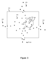
- FIG 3 depicts an illustrative environment in which the cooperative localization can be used.
- the environment 300 is substantially similar to the environment 100 described with regards to Figure 1 .
- the portable electronic devices 108 are associated with an estimate of the location of the portable electronic device, represented by the grey circles.
- a plurality of the portable electronic devices 108 inside the indoor space 102 includes an estimate of the portable electronic device's location.
- a further portable electronic device 202 is inside the indoor space 102 and does not have an associated location, represented by the white circle.
- the portable electronic device 202 receives a plurality of Bluetooth signals from portable electronic devices 208a, 208b, 208c that are within Bluetooth communication range of the portable electronic device.
- Bluetooth radios typically have a communication range of approximately 10 meters, represented by the broken-line circle 206.
- the location estimate of the portable electronic device 202 can be determined. As described above with regards to Figure 2 , the location of the portable electronic device 202 can be determined as a weighted average of the locations of portable electronic devices 208a, 208b, 208c. The weighting value can be based on the signal strength of the received Bluetooth signals. Once the location of the portable electronic device is estimated, it can be used to determine location estimates of other portable electronic devices inside the indoor space 102.
- the cooperative localization technique described above requires that a location be associated with a plurality of portable electronic devices located within the indoor space 102. As previously described, the portable electronic devices are unable to determine their locations using GPS due to the poor reception of the GPS signal inside the indoor location 102. As such, it is necessary to provide a means for providing location information inside the indoor space 102. As described further below with regards to Figures 4 and 5 , the portable electronic devices can utilize inertial navigation, based on accelerometers and gyroscopes of the portable electronic device, to determine the device location as the user enters the indoor location.
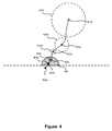
- Figure 4 depicts an illustrative embodiment of extending location information inside of an indoor location.
- Figure 4 depicts a path of a user 402a, 402b, 402c, 402d, 402e, 402f as they enter the indoor space, such as the indoor space 102.
- the location of the user, or more particularly the portable electronic device of the user may be known to a high degree of accuracy, depicted graphically with the black circle, for example using GPS signals.
- the portable electronic device loses the GPS reception and begins to use the inertial navigation of the device.
- the inertial navigation of the portable electronic device provides a dead reckoning of the movement of the portable electronic device.
- the error associated with the location estimate increases over time.
- the accuracy of the location estimate is depicted graphically with the darkness of the circle.
- the associated error of the location is further represented with the size of the dashed circles 404b, 404c, 404d, 404e, 404f.
- the portable electronic device may use the inertial navigation to extend the location inside of the indoor space.
- the high accuracy of the location information can be extended inside the indoor location represented by the shaded semi-circle 406.
- Figure 5 depicts the embodiment of Figure 4 when a further user enters the indoor space.
- the portable electronic device may use the GPS signals, as well as previously determined locations of portable electronic devices, to determine the location of the portable electronic device as it enters the indoor space.
- the user moves from outdoors through the indoor space 408a, 408b, 408c, 408d, 408e, 408f, 408g.
- the accuracy of the location estimate may decrease as the user moves inside the indoor space.
- the error associated with the location estimate is represented graphically in Figure 5 with the size of the broken-line circle 4 loc, 4 lod, 4 loe, 410f, 410g.
- the area associated with accurate location information is extended further inside the indoor space, as represented by the shaded semi-circle 412.
- the technique for extending the location estimates into the indoor space described above with reference to Figures 4 and 5 are intended to be illustrative in nature.
- a number of users are required to be entering, exiting, or moving around within the indoor space.
- the accuracy of the location estimates can be improved, and as such, the location information can eventually extend to cover the entire indoor space.
- the cooperative localization technique is particularly well suited to public spaces that have a large number of people within at any given time, such as malls, museums, or other buildings. From the above, as more users enter the indoor space, the location estimates will improve. As such, the cooperative localization technique has a convergence time that is dependent upon the arrival and departure rates of users.
- FIG. 6 depicts an environment for determining a cooperative location estimate of portable electronic devices.
- the environment 600 includes one or more localization servers 602 connected to a network 604.
- the network 604 connects the servers 602 to a communication infrastructure, such as a Wi-Fi communication network 606 and/or a cellular or mobile wide area network communication infrastructure 608.
- the communication infrastructure is used to communicate wirelessly between the server 602 and one or more wireless devices 610a, 610b, 610c, 610d.
- the wireless devices 610a, 610b, 610c, 610d may include a GPS receiver for receiving GPS signals from a GPS system 612.
- the portable electronic devices 610a, 610b, 610c, 610d may further include an inertial navigation system for providing a dead reckoning of the movement of the portable electronic device from a known location.
- the server 602 includes cooperative localization functionality for providing an estimate of the portable electronic devices using the Bluetooth radios that are visible from the portable electronic device.
- Each of the portable electronic devices sends location information to the server 602.
- the portable electronic device may extend the GPS location into the indoor space using inertial navigation.
- the error associated with the location as determined from the inertial navigation system increases.
- the portable electronic device may communicate its estimated location, determined using the inertial navigation, to the server 602.
- the server 602 associates the locations received from portable electronic devices with a Bluetooth radio identifier of the portable electronic device. As a result, the server 602 builds a corpus of location information associated with Bluetooth radio identifiers.
- the location information stored at the server 602 may be used to provide location estimates to other portable electronic devices.
- a portable electronic device for example query device 6loa, can determine Bluetooth radio identifiers of one or more portable electronic devices, such as portable electronic devices 610b, 610c, 610d, within Bluetooth communication range of the portable electronic device and communicate the Bluetooth radio IDs to the server 602 in a location query message.
- the server 602 may receive the Bluetooth radio identifiers from the portable electronic device and determine locations associated with the Bluetooth radio identifiers.
- the server 602 may then determine an estimate of the location for the portable electronic device using the retrieved locations.
- the query message sent from the portable electronic device may include the Bluetooth radio ID of the portable electronic device and the server may update the corpus of location information to include the determined estimate of the location of the portable electronic device.
- the portable electronic devices 610a, 610b, 610c, 610d can periodically send query messages to the server 602. For example, the portable electronic devices 610a, 610b, 610c, 610d can send location query messages every second. As such, the corpus of location information stored at the server 602 maintains current location estimates of the portable electronic devices that can be used to provide estimates of the locations for portable electronic devices.
- Figure 7 depicts a process of estimating a location of a portable electronic device.
- the localization server 602 stores a corpus of location information determined for various portable electronic devices, or more particularly for Bluetooth radio IDs of the portable electronic devices.
- user device 610a is attempting to determine an estimate for its location.
- the corpus of location information stored at the server 602 includes location information associated with Bluetooth radio IDs of a plurality of portable electronic devices 610b, 610c, 610d that are in Bluetooth communication range with the query device 610a.
- the query device 610a repeatedly determines (702a, 702b) an estimate for the location.
- the process begins with the query device 610a broadcasting a Bluetooth Inquiry message (704).
- the Bluetooth Inquiry message (704) is received by the plurality of in-range portable electronic devices 610b-d that are within Bluetooth communication range of the query device 610a.
- the Inquiry message is received at the portable electronic devices 610b-d, they send a response message back to the query device 610a (706).
- the response message includes the respective Bluetooth radio ID of the portable electronic devices 610b-d.
- the response messages are received at the query device 610a.
- the portable electronic device may determine a received signal strength associated with the received response messages.
- the query device 610a sends a localization request to the server 602 (708).
- the localization request may include the received Bluetooth IDs as well as the associated received signal strength indication associated with the Bluetooth IDs.
- the localization request may further include a Bluetooth ID of the query device 610a.
- the server 602 receives the localization request and determines the location estimate for the query device 610a and then stores the location estimate associated with the Bluetooth radio ID of the query portable electronic device (710).
- the server 602 sends the location estimate back to the query device 610a in a localization response message (712).
- the process of determining a location estimate (702a) may be periodically repeated by the portable electronic device (702b) , however, in an alterative embodiment, the inquiry message (706) may not be generated by query device 610a, rather transmitter identifiers broadcast from "discoverable" in-range portable electronic devices 610b-d are received in a listening mode at the query device 610a.
- the broadcast messages may be generated by the in-range portable electronic device 610b-d during operation or configuration in a discoverable mode.
- the query device 610a will simply "see" in-range portable electronic devices 610b-d, assuming they are discoverable (707), and report the sighting of the transmitter IDs to the server 602 (708).
- Such discoverable portable electronic devices chirp their ID over the BT radio at frequent intervals (every few seconds) and this chirp can be heard by all nearby devices with their BT receivers turned ON. Thus inter-device communication is not a necessity to determine in-range device for localization.
- Figure 8 depicts a process of estimating a location of a portable electronic device.
- Figure 8 is similar to the process of Figure 7 ; however, the process of Figure 8 includes the ability to extend the location information determined using GPS with the use of the internal navigation system of portable electronic devices. As such, the process allows location information to be extended to within the indoor space, allowing location estimates for other portable electronic devices to be determined.
- the process described with regards to Figure 8 begins when the portable electronic device, query device 610a, loses GPS signal reception (802). Upon losing GPS reception, the query device 610a may send the last location information to the server 602 (804), which stores the location with the Bluetooth radio ID (806). Once the query device 610a loses the GPS reception, the query device 610a initiates its inertial navigation system (808). The inertial navigation system of the query device 610a determines the dead reckoning of the portable electronic device. As the location is updated based on the inertial navigation system, the error associated with the determined location increases. At a certain point, the error of the inertial navigation crosses an error threshold (810).
- the query device 610a sends the location determined using the inertial navigation system to the server (812).
- the server 602a receives and stores the location information associated with the Bluetooth radio ID of the query device 610a (814).
- the query device 610a initiates the cooperative localization process (816).
- the cooperative localization process includes the query device 610a.
- the portable electronic device may broadcast a device Inquiry message (818) which is received with the other portable electronic devices 610b-d in Bluetooth communication range and sends the Bluetooth IDs of the portable electronic devices 610b-d back to the portable electronic devices 610a in Inquiry response messages (820).
- the query device 610a may passively listen for broadcasts from other discoverable portable electronic devices 610b-d and not be required to communicate directly with the other portable electronic device 610b-d.
- the query device 610a sends the received Bluetooth radio IDs to the localization server 602 in a localization request message (822).
- the server 602 receives the localization request message and estimates the location of the query device 610a (824).
- the server 602 stores the estimated location associated with the Bluetooth radio ID of the query device 610a (826) and returns the estimated location back to the query device 610a in a localization request message (828).
- the query device 610a may use the inertial navigation system to extend the location estimate (830) until an error of the inertial navigation location crosses the error threshold (832). Once the inertial navigation location crosses the error threshold, the query device 610a sends the location information to the server 602 (834). The server 602 receives the location information and stores the location (836) associated with the Bluetooth radio ID of the query device 610a.
- the process described above with reference to Figure 8 may be used by a plurality of portable electronic devices 610a -d to extend location information from a high accuracy location, determined for example using GPS, into an area where the high accuracy location information is not available.
- the cooperative localization process can provide estimates of portable electronic devices in an indoor location, or in locations without GPS reception.
- the cooperative localization process does not require a large infrastructure to be installed within the indoor location in order to provide the location information, nor does it require any modification to the hardware of the portable electronic devices.
- the cooperative localization process uses short-range radio IDs, such as Bluetooth, associated with portable electronic devices that are in close proximity to the query portable electronic device to determine a location estimate.
- the radio IDs are provided to a server that stores current location estimates associated with radio IDs, which allows the server to estimate a location for the query portable electronic device.
- the Bluetooth radio devices are described as being provided by portable electronic devices, it is contemplated that the location estimate may be improved in low traffic areas using one or more beacons.
- the beacons may be provided by one or more fixed Bluetooth radios at known locations.
- the server may treat the beacon location information in a similar manner to the locations associated with the portable electronic devices; however, as will be appreciated, the location information associated with the portable electronic devices may be periodically culled from the corpus, while the fixed locations of the beacons may be permanently stored in the corpus.
- FIG. 9 show a block diagram of a portable electronic device 900 in accordance with an illustrative embodiment.
- a processor 902 a multiple core processor or multiple processors may interface with components or modules of the portable electronic device to provide functionality required.
- a touch-sensitive interface is provided by a touch-sensitive display 918 coupled to the processor 902.
- the touch-sensitive display 918 may be any suitable touch-sensitive display, such as a capacitive, resistive, infrared, dispersive signal, acoustic pulse recognition, optical imaging, surface acoustic wave (SAW).
- the touch-sensitive display 918 is a capacitive touch-sensitive display which includes a capacitive touch-sensitive overlay 914, on a display 912 coupled to a controller 916.
- the overlay 914 may be an assembly of multiple layers in a stack which may include, for example, a substrate, a ground shield layer, a barrier layer, one or more capacitive touch sensor layers separated by a substrate or other barrier, and a cover.
- the processor 902 and other components of the device are powered by a power source 960 and interfaces with memory 910 providing an operating system 946 and programs or applications 948 providing instructions for execution by the processor 902.
- Random access memory 908 is provided for the storage of the instructions and for processing data to be sent to or received from various components of the portable electronic device.
- the instructions when executed by the processor 902 may configure the portable electronic device to provide varying functionality for displaying data.
- the functionality may include functionality 950 for providing a cooperative localization client on the portable electronic device as described above. Although the functionality 950 is depicted as being separate from the operating system 946, it is contemplated that the functionality could be provided as component of the operating system.
- a communication subsystem 904 is provided for enabling data to be sent or received with a local area network 954 or wide area network utilizing different physical layer and access technology implementations.
- the communication subsystem may be utilized to request and pre-cache data based upon possible gesture event outcomes.
- the device may include connections to other subsystems 934, including a subscriber identity module or removable user identity module 962 may be provided depending on the requirement of the particular network access technology to provide user access or identify information.
- Short-range communications such as a Bluetooth radio, 932 may also be provided and may further include near-field communication (NFC), radio frequency identifier (RFID), ZigBee, IEEE 802.15 or other short-range communication technologies.
- the portable electronic device may also be provided with a data port 926 and auxiliary input/output interface for sending and receiving data.
- a microphone 930 and speaker 928 may also be provided to enable audio communications via the portable electronic device 900.
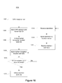
- FIG. 10 depicts a method of cooperative localization of a portable electronic device.
- the method 1000 begins when GPS reception is lost at the portable electronic device (1002). Once the GPS reception is lost, the portable electronic device sends its last location information to a localization server that stores location information associated with radio IDs (1004).
- the portable electronic device initiates an inertial navigation system (1006) that determines a dead reckoning of the position of the portable electronic device based on the last GPS location and sensors, such as accelerometers and gyroscopes of the portable electronic device.
- the portable electronic device periodically sends the inertial navigation location estimate to the cooperative localization server (1008) and then determines if the error associated with the inertial navigation location estimate is above a location error estimate (1010).
- the portable electronic device may send an updated inertial navigation location estimate to the cooperative localization server after a short delay. If the error is above a location error threshold (Yes at 1010) the portable electronic device initiates Bluetooth location estimation functionality (1012).
- the portable electronic device receives device transmitter identifiers from portable electronic devices in communication range (1014).
- the broadcast information may be provided as part of a discoverable mode in which the portable electronic devices 610b-d broadcast discoverable messages containing their device identifier such as in a Bluetooth discoverable mode.
- the query device 610a may send an inquiry message which is broadcast to nearby devices 610b-d which devices in turn respond with a message including the transmitter or radio ID of the responding portable electronic devices.
- the query portable electronic device sends the Bluetooth identifiers to the cooperative localization server (1016).
- the cooperative localization server determines an estimate for the location of the query portable electronic device and sends the location estimate back to the query portable electronic device.
- the portable electronic device receives the location estimate (1018) which can then be used to provide location services.
- the method may use the inertial navigation system to provide a dead reckoning of the location of the portable electronic device from the received estimate and sends the inertial navigation location estimate to the cooperative localization server (1008).
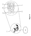
- FIG 11 depicts components of a cooperative localization server.
- the cooperative localization server 1100 may be used as the cooperative localization server 602 described above.
- the localization server 1100 may comprise one or more physical servers that are coupled to a communication network 1102.
- the localization server 1100 may be provided by a plurality of physical servers, although conceptually, the server 1100 is comprised of a central processing unit (CPU) 1104 that is coupled to a memory 1106 storing instructions 1108 providing cooperative localization functionality 1108.
- the server 1100 may further comprise non-volatile storage 1110 and one or more input/output (I/O) components 1112.
- I/O input/output
- Figure 12 depicts a method of estimating a location of a portable electronic device using radio IDs.
- the method 1200 may be implemented in a server by the execution of instructions stored in memory.
- the method 1200 populates a corpus of location information associated with radio identifiers (1202).
- the population of the location corpus comprises receiving location information from a portable electronic device (1204).
- the location information may be determined by portable electronic devices in various ways, including, for example, using a GPS receiver, or using an inertial navigation system.
- the received location information includes a Bluetooth radio identifier of the portable electronic device associated with the location information.
- the server stores the location information, associating the location with the Bluetooth radio ID (1206).
- the server may receive a location request message from a portable electronic device (1208) that includes Bluetooth radio IDs of nearby devices.
- the locations associated with the received Bluetooth radio IDs are retrieved from the stored information in the corpus (1210) and used to provide an estimate of the location of the portable electronic device (1212).
- the location request message may include an indication of received signal strengths associated with each of the Bluetooth radio IDs, which can be used to provide a weighting of respective locations in estimating a location.
- the cooperative localization process can be used to provide location estimates of portable electronic devices in an indoor space.
- the cooperative localization process may utilize previously estimated locations associated with different portable electronic devices in estimating the location of the portable electronic device.
- the cooperative localization server maintains a corpus of current location estimates of portable electronic devices associated with Bluetooth radio IDs.
- the cooperative localization process can be used in indoor spaces without requiring the installation and maintenance of a large number of location beacons.
- the cooperative localization technique may utilize fixed, or moving, beacons that can provide their location to a high degree of accuracy.
- any suitable computer readable media can be used for storing instructions for performing the methods described herein.
- computer readable media can be transitory or non-transitory.
- non-transitory computer readable media can include media such as magnetic media (such as hard disks, floppy disks, etc.), optical media (such as compact discs, digital video discs, Blu-ray discs, etc.), semiconductor media (such as flash memory, electrically programmable read only memory (EPROM), electrically erasable programmable read only memory (EEPROM), etc.), any suitable media that is not fleeting or devoid of any semblance of permanence during transmission, and/or any suitable tangible media.
- magnetic media such as hard disks, floppy disks, etc.
- optical media such as compact discs, digital video discs, Blu-ray discs, etc.
- semiconductor media such as flash memory, electrically programmable read only memory (EPROM), electrically erasable programmable read only memory (EEPROM), etc.
- EPROM electrically eras
- transitory computer readable media can include signals on networks, in wires, conductors, optical fibers, circuits, and any suitable media that is fleeting and devoid of any semblance of permanence during transmission, and/or any suitable intangible media.
Landscapes
- Physics & Mathematics (AREA)
- Engineering & Computer Science (AREA)
- General Physics & Mathematics (AREA)
- Radar, Positioning & Navigation (AREA)
- Remote Sensing (AREA)
- Electromagnetism (AREA)
- Position Fixing By Use Of Radio Waves (AREA)
- Navigation (AREA)
Priority Applications (1)
| Application Number | Priority Date | Filing Date | Title |
|---|---|---|---|
| EP12164887.7A EP2653881B1 (fr) | 2012-04-20 | 2012-04-20 | Localisation coopérative de dispositifs électroniques portables |
Applications Claiming Priority (1)
| Application Number | Priority Date | Filing Date | Title |
|---|---|---|---|
| EP12164887.7A EP2653881B1 (fr) | 2012-04-20 | 2012-04-20 | Localisation coopérative de dispositifs électroniques portables |
Publications (2)
| Publication Number | Publication Date |
|---|---|
| EP2653881A1 true EP2653881A1 (fr) | 2013-10-23 |
| EP2653881B1 EP2653881B1 (fr) | 2018-06-13 |
Family
ID=46025524
Family Applications (1)
| Application Number | Title | Priority Date | Filing Date |
|---|---|---|---|
| EP12164887.7A Active EP2653881B1 (fr) | 2012-04-20 | 2012-04-20 | Localisation coopérative de dispositifs électroniques portables |
Country Status (1)
| Country | Link |
|---|---|
| EP (1) | EP2653881B1 (fr) |
Cited By (3)
| Publication number | Priority date | Publication date | Assignee | Title |
|---|---|---|---|---|
| GB2509157A (en) * | 2012-12-21 | 2014-06-25 | Crowd Connected Ltd | Forming an image using plural pixel devices and determining the position of a plurality of mobile devices |
| WO2017070864A1 (fr) * | 2015-10-28 | 2017-05-04 | 深圳市奥星澳科技有限公司 | Procédé et système de traitement de données, terminal intelligent et serveur |
| US10470155B2 (en) | 2017-11-30 | 2019-11-05 | Abl Ip Holding Llc | Commissioning of an indoor positioning system using a secondary positioning system |
Families Citing this family (1)
| Publication number | Priority date | Publication date | Assignee | Title |
|---|---|---|---|---|
| CN110213713B (zh) * | 2019-04-28 | 2020-06-23 | 浙江大学 | 一种基于时空域联合处理的集中式协作定位系统和方法 |
Citations (2)
| Publication number | Priority date | Publication date | Assignee | Title |
|---|---|---|---|---|
| US20030220116A1 (en) * | 2002-04-23 | 2003-11-27 | Axis Ab | Method and apparatus for determining the position of a portable device |
| US20080248813A1 (en) * | 2007-04-06 | 2008-10-09 | Palm, Inc. | System and Methods for Obtaining Coarse Location for a Mobile Device |
Family Cites Families (1)
| Publication number | Priority date | Publication date | Assignee | Title |
|---|---|---|---|---|
| EP1788357A1 (fr) * | 2005-11-16 | 2007-05-23 | Alcatel Lucent | Système de localisation d'utilisateur pieton |
-
2012
- 2012-04-20 EP EP12164887.7A patent/EP2653881B1/fr active Active
Patent Citations (2)
| Publication number | Priority date | Publication date | Assignee | Title |
|---|---|---|---|---|
| US20030220116A1 (en) * | 2002-04-23 | 2003-11-27 | Axis Ab | Method and apparatus for determining the position of a portable device |
| US20080248813A1 (en) * | 2007-04-06 | 2008-10-09 | Palm, Inc. | System and Methods for Obtaining Coarse Location for a Mobile Device |
Cited By (5)
| Publication number | Priority date | Publication date | Assignee | Title |
|---|---|---|---|---|
| GB2509157A (en) * | 2012-12-21 | 2014-06-25 | Crowd Connected Ltd | Forming an image using plural pixel devices and determining the position of a plurality of mobile devices |
| GB2531186A (en) * | 2012-12-21 | 2016-04-13 | Crowd Connected Ltd | Methods and Apparatus For Forming Image Using, And Finding Positions Of, Plural Pixel Devices |
| GB2531186B (en) * | 2012-12-21 | 2016-10-26 | Crowd Connected Ltd | Methods and Apparatus For Finding Positions Of Plural Mobile Devices |
| WO2017070864A1 (fr) * | 2015-10-28 | 2017-05-04 | 深圳市奥星澳科技有限公司 | Procédé et système de traitement de données, terminal intelligent et serveur |
| US10470155B2 (en) | 2017-11-30 | 2019-11-05 | Abl Ip Holding Llc | Commissioning of an indoor positioning system using a secondary positioning system |
Also Published As
| Publication number | Publication date |
|---|---|
| EP2653881B1 (fr) | 2018-06-13 |
Similar Documents
| Publication | Publication Date | Title |
|---|---|---|
| US9277524B2 (en) | Cooperative localization of portable electronic devices | |
| KR101429954B1 (ko) | 인빌딩 전파 환경 맵 생성 방법과 그를 위한 장치 | |
| US10192416B2 (en) | Indoor positioning and tracking using a multi-band wireless networking system | |
| US8649800B2 (en) | Direction-enhanced navigation | |
| EP2556706B1 (fr) | Mise à jour d'un modèle radio | |
| US9939517B2 (en) | Determining a location of a transmitter device | |
| JP5450689B2 (ja) | 測位システムにおける連続データ最適化 | |
| JP6370886B2 (ja) | ベニュー測位能力に適応するための方法 | |
| EP3295207B1 (fr) | Sélection de station de base pour positionnement/localisation sur la base d'une indication de capacité | |
| KR101286169B1 (ko) | 무선 통신 단말의 위치 측정 장치, 위치 측정 방법 및 핑거프린트 정보 수집 방법, 핑거프린트 서버 및 그의 위치 제공 방법 | |
| CN103828401A (zh) | 移动设备入口转移的可能性 | |
| CN117396773A (zh) | 确定移动设备的位置信息 | |
| US20130084887A1 (en) | Using wired endpoints to determine position information for wireless endpoints in a network | |
| JP2016517665A (ja) | サーバベースのモバイルデバイス領域候補位置決定モード選択 | |
| WO2013173361A1 (fr) | Estimation d'une position extérieure d'un dispositif mobile au voisinage d'un ou de plusieurs environnements intérieurs | |
| US9609470B2 (en) | Data routing for positioning | |
| CN119471564A (zh) | 移动通信设备的网络辅助自定位 | |
| KR20180024684A (ko) | 위치측위 기반 서비스 제공 장치, 위치측위 기반 서비스 제공 방법 및 기록매체 | |
| EP2928245A1 (fr) | Point d'accès sans fil, procédé d'implémentation d'émetteur-récepteur, dispositif utilisateur mobile et procédé implémenté par l'utilisateur pour une localisation | |
| US20150133150A1 (en) | Apparatus for determining indoor location and method for determining indoor location in multi-story building using the same | |
| EP2653881B1 (fr) | Localisation coopérative de dispositifs électroniques portables | |
| US20160066156A1 (en) | Selection of Location-Determination Information | |
| KR101417922B1 (ko) | 단말기 위치 측위 방법 및 장치 | |
| CN108476487B (zh) | 电子装置和托管位置服务的服务器 | |
| Bahillo et al. | WAY: seamless positioning using a smart device |
Legal Events
| Date | Code | Title | Description |
|---|---|---|---|
| PUAI | Public reference made under article 153(3) epc to a published international application that has entered the european phase |
Free format text: ORIGINAL CODE: 0009012 |
|
| 17P | Request for examination filed |
Effective date: 20120420 |
|
| AK | Designated contracting states |
Kind code of ref document: A1 Designated state(s): AL AT BE BG CH CY CZ DE DK EE ES FI FR GB GR HR HU IE IS IT LI LT LU LV MC MK MT NL NO PL PT RO RS SE SI SK SM TR |
|
| AX | Request for extension of the european patent |
Extension state: BA ME |
|
| RAP1 | Party data changed (applicant data changed or rights of an application transferred) |
Owner name: BLACKBERRY LIMITED |
|
| 17Q | First examination report despatched |
Effective date: 20131211 |
|
| GRAP | Despatch of communication of intention to grant a patent |
Free format text: ORIGINAL CODE: EPIDOSNIGR1 |
|
| STAA | Information on the status of an ep patent application or granted ep patent |
Free format text: STATUS: GRANT OF PATENT IS INTENDED |
|
| INTG | Intention to grant announced |
Effective date: 20171109 |
|
| GRAS | Grant fee paid |
Free format text: ORIGINAL CODE: EPIDOSNIGR3 |
|
| GRAJ | Information related to disapproval of communication of intention to grant by the applicant or resumption of examination proceedings by the epo deleted |
Free format text: ORIGINAL CODE: EPIDOSDIGR1 |
|
| GRAL | Information related to payment of fee for publishing/printing deleted |
Free format text: ORIGINAL CODE: EPIDOSDIGR3 |
|
| STAA | Information on the status of an ep patent application or granted ep patent |
Free format text: STATUS: EXAMINATION IS IN PROGRESS |
|
| GRAR | Information related to intention to grant a patent recorded |
Free format text: ORIGINAL CODE: EPIDOSNIGR71 |
|
| STAA | Information on the status of an ep patent application or granted ep patent |
Free format text: STATUS: GRANT OF PATENT IS INTENDED |
|
| INTC | Intention to grant announced (deleted) | ||
| INTG | Intention to grant announced |
Effective date: 20180327 |
|
| GRAA | (expected) grant |
Free format text: ORIGINAL CODE: 0009210 |
|
| STAA | Information on the status of an ep patent application or granted ep patent |
Free format text: STATUS: THE PATENT HAS BEEN GRANTED |
|
| AK | Designated contracting states |
Kind code of ref document: B1 Designated state(s): AL AT BE BG CH CY CZ DE DK EE ES FI FR GB GR HR HU IE IS IT LI LT LU LV MC MK MT NL NO PL PT RO RS SE SI SK SM TR |
|
| REG | Reference to a national code |
Ref country code: GB Ref legal event code: FG4D |
|
| REG | Reference to a national code |
Ref country code: CH Ref legal event code: EP Ref country code: AT Ref legal event code: REF Ref document number: 1009048 Country of ref document: AT Kind code of ref document: T Effective date: 20180615 |
|
| REG | Reference to a national code |
Ref country code: IE Ref legal event code: FG4D |
|
| REG | Reference to a national code |
Ref country code: DE Ref legal event code: R096 Ref document number: 602012047356 Country of ref document: DE |
|
| REG | Reference to a national code |
Ref country code: NL Ref legal event code: MP Effective date: 20180613 |
|
| REG | Reference to a national code |
Ref country code: LT Ref legal event code: MG4D |
|
| PG25 | Lapsed in a contracting state [announced via postgrant information from national office to epo] |
Ref country code: ES Free format text: LAPSE BECAUSE OF FAILURE TO SUBMIT A TRANSLATION OF THE DESCRIPTION OR TO PAY THE FEE WITHIN THE PRESCRIBED TIME-LIMIT Effective date: 20180613 Ref country code: SE Free format text: LAPSE BECAUSE OF FAILURE TO SUBMIT A TRANSLATION OF THE DESCRIPTION OR TO PAY THE FEE WITHIN THE PRESCRIBED TIME-LIMIT Effective date: 20180613 Ref country code: FI Free format text: LAPSE BECAUSE OF FAILURE TO SUBMIT A TRANSLATION OF THE DESCRIPTION OR TO PAY THE FEE WITHIN THE PRESCRIBED TIME-LIMIT Effective date: 20180613 Ref country code: NO Free format text: LAPSE BECAUSE OF FAILURE TO SUBMIT A TRANSLATION OF THE DESCRIPTION OR TO PAY THE FEE WITHIN THE PRESCRIBED TIME-LIMIT Effective date: 20180913 Ref country code: LT Free format text: LAPSE BECAUSE OF FAILURE TO SUBMIT A TRANSLATION OF THE DESCRIPTION OR TO PAY THE FEE WITHIN THE PRESCRIBED TIME-LIMIT Effective date: 20180613 Ref country code: CY Free format text: LAPSE BECAUSE OF FAILURE TO SUBMIT A TRANSLATION OF THE DESCRIPTION OR TO PAY THE FEE WITHIN THE PRESCRIBED TIME-LIMIT Effective date: 20180613 Ref country code: BG Free format text: LAPSE BECAUSE OF FAILURE TO SUBMIT A TRANSLATION OF THE DESCRIPTION OR TO PAY THE FEE WITHIN THE PRESCRIBED TIME-LIMIT Effective date: 20180913 |
|
| PG25 | Lapsed in a contracting state [announced via postgrant information from national office to epo] |
Ref country code: GR Free format text: LAPSE BECAUSE OF FAILURE TO SUBMIT A TRANSLATION OF THE DESCRIPTION OR TO PAY THE FEE WITHIN THE PRESCRIBED TIME-LIMIT Effective date: 20180914 Ref country code: HR Free format text: LAPSE BECAUSE OF FAILURE TO SUBMIT A TRANSLATION OF THE DESCRIPTION OR TO PAY THE FEE WITHIN THE PRESCRIBED TIME-LIMIT Effective date: 20180613 Ref country code: RS Free format text: LAPSE BECAUSE OF FAILURE TO SUBMIT A TRANSLATION OF THE DESCRIPTION OR TO PAY THE FEE WITHIN THE PRESCRIBED TIME-LIMIT Effective date: 20180613 Ref country code: LV Free format text: LAPSE BECAUSE OF FAILURE TO SUBMIT A TRANSLATION OF THE DESCRIPTION OR TO PAY THE FEE WITHIN THE PRESCRIBED TIME-LIMIT Effective date: 20180613 |
|
| REG | Reference to a national code |
Ref country code: AT Ref legal event code: MK05 Ref document number: 1009048 Country of ref document: AT Kind code of ref document: T Effective date: 20180613 |
|
| PG25 | Lapsed in a contracting state [announced via postgrant information from national office to epo] |
Ref country code: NL Free format text: LAPSE BECAUSE OF FAILURE TO SUBMIT A TRANSLATION OF THE DESCRIPTION OR TO PAY THE FEE WITHIN THE PRESCRIBED TIME-LIMIT Effective date: 20180613 |
|
| PG25 | Lapsed in a contracting state [announced via postgrant information from national office to epo] |
Ref country code: CZ Free format text: LAPSE BECAUSE OF FAILURE TO SUBMIT A TRANSLATION OF THE DESCRIPTION OR TO PAY THE FEE WITHIN THE PRESCRIBED TIME-LIMIT Effective date: 20180613 Ref country code: RO Free format text: LAPSE BECAUSE OF FAILURE TO SUBMIT A TRANSLATION OF THE DESCRIPTION OR TO PAY THE FEE WITHIN THE PRESCRIBED TIME-LIMIT Effective date: 20180613 Ref country code: SK Free format text: LAPSE BECAUSE OF FAILURE TO SUBMIT A TRANSLATION OF THE DESCRIPTION OR TO PAY THE FEE WITHIN THE PRESCRIBED TIME-LIMIT Effective date: 20180613 Ref country code: EE Free format text: LAPSE BECAUSE OF FAILURE TO SUBMIT A TRANSLATION OF THE DESCRIPTION OR TO PAY THE FEE WITHIN THE PRESCRIBED TIME-LIMIT Effective date: 20180613 Ref country code: IS Free format text: LAPSE BECAUSE OF FAILURE TO SUBMIT A TRANSLATION OF THE DESCRIPTION OR TO PAY THE FEE WITHIN THE PRESCRIBED TIME-LIMIT Effective date: 20181013 Ref country code: AT Free format text: LAPSE BECAUSE OF FAILURE TO SUBMIT A TRANSLATION OF THE DESCRIPTION OR TO PAY THE FEE WITHIN THE PRESCRIBED TIME-LIMIT Effective date: 20180613 Ref country code: PL Free format text: LAPSE BECAUSE OF FAILURE TO SUBMIT A TRANSLATION OF THE DESCRIPTION OR TO PAY THE FEE WITHIN THE PRESCRIBED TIME-LIMIT Effective date: 20180613 |
|
| PG25 | Lapsed in a contracting state [announced via postgrant information from national office to epo] |
Ref country code: IT Free format text: LAPSE BECAUSE OF FAILURE TO SUBMIT A TRANSLATION OF THE DESCRIPTION OR TO PAY THE FEE WITHIN THE PRESCRIBED TIME-LIMIT Effective date: 20180613 Ref country code: SM Free format text: LAPSE BECAUSE OF FAILURE TO SUBMIT A TRANSLATION OF THE DESCRIPTION OR TO PAY THE FEE WITHIN THE PRESCRIBED TIME-LIMIT Effective date: 20180613 |
|
| REG | Reference to a national code |
Ref country code: DE Ref legal event code: R097 Ref document number: 602012047356 Country of ref document: DE |
|
| PLBE | No opposition filed within time limit |
Free format text: ORIGINAL CODE: 0009261 |
|
| STAA | Information on the status of an ep patent application or granted ep patent |
Free format text: STATUS: NO OPPOSITION FILED WITHIN TIME LIMIT |
|
| 26N | No opposition filed |
Effective date: 20190314 |
|
| PG25 | Lapsed in a contracting state [announced via postgrant information from national office to epo] |
Ref country code: DK Free format text: LAPSE BECAUSE OF FAILURE TO SUBMIT A TRANSLATION OF THE DESCRIPTION OR TO PAY THE FEE WITHIN THE PRESCRIBED TIME-LIMIT Effective date: 20180613 Ref country code: SI Free format text: LAPSE BECAUSE OF FAILURE TO SUBMIT A TRANSLATION OF THE DESCRIPTION OR TO PAY THE FEE WITHIN THE PRESCRIBED TIME-LIMIT Effective date: 20180613 |
|
| PG25 | Lapsed in a contracting state [announced via postgrant information from national office to epo] |
Ref country code: AL Free format text: LAPSE BECAUSE OF FAILURE TO SUBMIT A TRANSLATION OF THE DESCRIPTION OR TO PAY THE FEE WITHIN THE PRESCRIBED TIME-LIMIT Effective date: 20180613 |
|
| REG | Reference to a national code |
Ref country code: CH Ref legal event code: PL |
|
| REG | Reference to a national code |
Ref country code: BE Ref legal event code: MM Effective date: 20190430 |
|
| PG25 | Lapsed in a contracting state [announced via postgrant information from national office to epo] |
Ref country code: LU Free format text: LAPSE BECAUSE OF NON-PAYMENT OF DUE FEES Effective date: 20190420 Ref country code: MC Free format text: LAPSE BECAUSE OF FAILURE TO SUBMIT A TRANSLATION OF THE DESCRIPTION OR TO PAY THE FEE WITHIN THE PRESCRIBED TIME-LIMIT Effective date: 20180613 |
|
| PG25 | Lapsed in a contracting state [announced via postgrant information from national office to epo] |
Ref country code: LI Free format text: LAPSE BECAUSE OF NON-PAYMENT OF DUE FEES Effective date: 20190430 Ref country code: CH Free format text: LAPSE BECAUSE OF NON-PAYMENT OF DUE FEES Effective date: 20190430 |
|
| PG25 | Lapsed in a contracting state [announced via postgrant information from national office to epo] |
Ref country code: BE Free format text: LAPSE BECAUSE OF NON-PAYMENT OF DUE FEES Effective date: 20190430 |
|
| PG25 | Lapsed in a contracting state [announced via postgrant information from national office to epo] |
Ref country code: TR Free format text: LAPSE BECAUSE OF FAILURE TO SUBMIT A TRANSLATION OF THE DESCRIPTION OR TO PAY THE FEE WITHIN THE PRESCRIBED TIME-LIMIT Effective date: 20180613 |
|
| PG25 | Lapsed in a contracting state [announced via postgrant information from national office to epo] |
Ref country code: IE Free format text: LAPSE BECAUSE OF NON-PAYMENT OF DUE FEES Effective date: 20190420 |
|
| PG25 | Lapsed in a contracting state [announced via postgrant information from national office to epo] |
Ref country code: PT Free format text: LAPSE BECAUSE OF FAILURE TO SUBMIT A TRANSLATION OF THE DESCRIPTION OR TO PAY THE FEE WITHIN THE PRESCRIBED TIME-LIMIT Effective date: 20181015 |
|
| PG25 | Lapsed in a contracting state [announced via postgrant information from national office to epo] |
Ref country code: HU Free format text: LAPSE BECAUSE OF FAILURE TO SUBMIT A TRANSLATION OF THE DESCRIPTION OR TO PAY THE FEE WITHIN THE PRESCRIBED TIME-LIMIT; INVALID AB INITIO Effective date: 20120420 Ref country code: MT Free format text: LAPSE BECAUSE OF FAILURE TO SUBMIT A TRANSLATION OF THE DESCRIPTION OR TO PAY THE FEE WITHIN THE PRESCRIBED TIME-LIMIT Effective date: 20180613 |
|
| PG25 | Lapsed in a contracting state [announced via postgrant information from national office to epo] |
Ref country code: MK Free format text: LAPSE BECAUSE OF FAILURE TO SUBMIT A TRANSLATION OF THE DESCRIPTION OR TO PAY THE FEE WITHIN THE PRESCRIBED TIME-LIMIT Effective date: 20180613 |
|
| P01 | Opt-out of the competence of the unified patent court (upc) registered |
Effective date: 20230518 |
|
| PGFP | Annual fee paid to national office [announced via postgrant information from national office to epo] |
Ref country code: DE Payment date: 20250417 Year of fee payment: 14 |
|
| PGFP | Annual fee paid to national office [announced via postgrant information from national office to epo] |
Ref country code: FR Payment date: 20250422 Year of fee payment: 14 |
|
| PGFP | Annual fee paid to national office [announced via postgrant information from national office to epo] |
Ref country code: GB Payment date: 20260324 Year of fee payment: 15 |