EP2654055B1 - Drehschalter für Haushaltsgeräte oder dergleichen - Google Patents
Drehschalter für Haushaltsgeräte oder dergleichen Download PDFInfo
- Publication number
- EP2654055B1 EP2654055B1 EP12382153.0A EP12382153A EP2654055B1 EP 2654055 B1 EP2654055 B1 EP 2654055B1 EP 12382153 A EP12382153 A EP 12382153A EP 2654055 B1 EP2654055 B1 EP 2654055B1
- Authority
- EP
- European Patent Office
- Prior art keywords
- base
- switch
- wheel
- plastic support
- control shaft
- Prior art date
- Legal status (The legal status is an assumption and is not a legal conclusion. Google has not performed a legal analysis and makes no representation as to the accuracy of the status listed.)
- Active
Links
Images


Classifications
-
- H—ELECTRICITY
- H01—ELECTRIC ELEMENTS
- H01H—ELECTRIC SWITCHES; RELAYS; SELECTORS; EMERGENCY PROTECTIVE DEVICES
- H01H1/00—Contacts
- H01H1/12—Contacts characterised by the manner in which co-operating contacts engage
- H01H1/14—Contacts characterised by the manner in which co-operating contacts engage by abutting
- H01H1/20—Bridging contacts
-
- H—ELECTRICITY
- H01—ELECTRIC ELEMENTS
- H01H—ELECTRIC SWITCHES; RELAYS; SELECTORS; EMERGENCY PROTECTIVE DEVICES
- H01H19/00—Switches operated by an operating part which is rotatable about a longitudinal axis thereof and which is acted upon directly by a solid body external to the switch, e.g. by a hand
- H01H19/54—Switches operated by an operating part which is rotatable about a longitudinal axis thereof and which is acted upon directly by a solid body external to the switch, e.g. by a hand the operating part having at least five or an unspecified number of operative positions
- H01H19/60—Angularly-movable actuating part carrying no contacts
- H01H19/62—Contacts actuated by radial cams
- H01H19/626—Contacts actuated by radial cams actuating bridging contacts
-
- H—ELECTRICITY
- H01—ELECTRIC ELEMENTS
- H01H—ELECTRIC SWITCHES; RELAYS; SELECTORS; EMERGENCY PROTECTIVE DEVICES
- H01H19/00—Switches operated by an operating part which is rotatable about a longitudinal axis thereof and which is acted upon directly by a solid body external to the switch, e.g. by a hand
- H01H19/02—Details
- H01H19/10—Movable parts; Contacts mounted thereon
- H01H19/11—Movable parts; Contacts mounted thereon with indexing means
-
- H—ELECTRICITY
- H01—ELECTRIC ELEMENTS
- H01H—ELECTRIC SWITCHES; RELAYS; SELECTORS; EMERGENCY PROTECTIVE DEVICES
- H01H3/00—Mechanisms for operating contacts
- H01H3/32—Driving mechanisms, i.e. for transmitting driving force to the contacts
- H01H3/42—Driving mechanisms, i.e. for transmitting driving force to the contacts using cam or eccentric
-
- H—ELECTRICITY
- H01—ELECTRIC ELEMENTS
- H01H—ELECTRIC SWITCHES; RELAYS; SELECTORS; EMERGENCY PROTECTIVE DEVICES
- H01H3/00—Mechanisms for operating contacts
- H01H3/32—Driving mechanisms, i.e. for transmitting driving force to the contacts
- H01H3/50—Driving mechanisms, i.e. for transmitting driving force to the contacts with indexing or locating means, e.g. indexing by ball and spring
Definitions
- the present invention relates to rotary switches for electrical appliances or the like.
- the present invention especially relates to switches that are mounted on different electrical appliances, although they are not exclusive to said appliances.
- the present invention also relates to switches for other types of applications in the industrial field or professional applications.
- the geometry and make-up of the electrical circuit is a determining factor regarding the functionality and safety of the electrical switching, and also determines the cost of the elementary circuit, making a more or less efficient use of the materials with relation to their type and quantity.
- the pivoting opening breaking systems and the vertical opening systems are generally associated with rotating manoeuvre systems.
- Rotary switches for electrical appliances comprise a rotating control shaft rotatably mounted on a frame, said rotating control shaft being provided with a plurality of cam disks respectively associated to a plurality of current breaking devices, each current breaking device being faced to a cam disk and housed in a base pertaining to the frame, and being linearly displaceable within the base between a connected position and a disconnected position of a pair of electrical connecting strips integrally joined to the frame, so that each cam disk, depending on the rotational position of the rotating control shaft, is able to connect or disconnect said current breaking device.
- imprecise elements that affect the safety and functionality of the switch.
- These imprecise elements are related to the geometry of the mobile element or elements of the current breaking device.
- a uniform and balanced movement of the current breaking device improves the efficiency of the breaking capacity of this device.
- the efficiency in the breaking capacity of the corresponding device greatly influences the life of the electrical contact elements and, consequently, the reliability and durability of the switch.
- rotary switches whose current breaking device comprises a metal bridge housed in a base and coupled on two compression springs. Said metal bridge can be moved linearly along the walls of the base between the connected position with the metal strips and disconnected position when said metal bridge is pushed by the cam disk.
- this type of rotary switch has the drawback that the metal bridge directly receives the mechanical fatigue stress produced at the cyclical closure of the circuit, with the consequent deterioration and bad operation of the switch.
- Another drawback is that there is a certain hollow space between the metal bridge and the walls of the housing of the base, which leads to undesired movements being produced in both directions perpendicular to the direction of displacement of the metal bridge within the base.
- the known rotary switches additionally comprise a positioning device of said rotating control shaft which can define a series of preset radial positions associated to different switch functions.
- Positioning devices for the rotating control shaft comprise a positioning wheel housed in a base pertaining to the frame, mounted on elastic means and facing a rotating manoeuvre organ integrally joined to the rotating control shaft, said manoeuvre organ including a toothed profile in the shape of a ratchet.
- Said positioning wheel comprises a central protuberance which can fit into cavities between every two cogs of the manoeuvre organ, said positioning wheel being displaceable linearly inside the base between a coupling position, wherein it is fixed between two cogs by means of the release force of the elastic means, and an uncoupling position, wherein it is pushed by one of the cogs compressing the elastic means, depending on the rotational position of the rotating control shaft.
- the systems with rotating manoeuvre organs are associated to a toothing system and to pressure elements to guarantee proper electrical contact and positioning reliability.
- the rotating manoeuvre systems with toothing systems must make it possible to change from one position to the adjacent position and must keep the resting position fixed.
- Document EP0443075 discloses a device according to the preamble of claim 1.
- the object of the rotary switch for electrical appliances or the like of the present invention is to resolve the drawbacks featured by the known rotary switches in the state of the art, providing a more effective rotary switch with a current breaking device and a manoeuvre organ positioning device optimised and with a lower assembly cost.
- the rotary switch for electrical appliances or the like of the present invention is of the type which comprises a rotating control shaft rotatably mounted on a frame, said rotating control shaft being provided with a plurality of cam disks, respectively, associated to a plurality of current breaking devices, each current breaking device being faced to a cam disk and housed in a base pertaining to the frame, and being linearly displaceable within the base between a connected position and a disconnected position of a pair of electrical connecting strips integrally joined to the frame, so that each cam disk, depending on the rotational position of the rotating control shaft, is able to connect or disconnect said current breaking device, and comprising a positioning device of said rotating control shaft that is able to define a series of preset radial positions associated with different functions of the switch, and is characterised in that each current breaking device comprises a mobile bridge assembly provided with a plastic support mounted on elastic means and a metal bridge coupled on said plastic support, said metal bridge being able to maintain direct contact with the respective strips by means of the release force of the elastic means in the connected position
- the geometry of the plastic support which supports the metal bridge permits the mechanical design of said metal bridge to be optimised, since all of the mechanical fatigue stress produced upon the cyclical closure of the circuit are not supported by the metal bridge, as occurs with the switches known in the state of the art, but are rather supported by the plastic support.
- This geometry is that permits the design of the metal bridge to be optimised with the use of reduced material thickness and, therefore, optimised as regards the production costs.
- the plastic support of the mobile bridge assembly comprises a core provided with fitting means for coupling with the metal bridge, a protuberance incorporated in a central zone of the core intended to make contact with the cam disk, and two pins substantially parallel to the direction of displacement of said mobile bridge assembly within in the base.
- the plastic support includes means for guiding the displacement of said mobile bridge assembly.
- the means for guiding the plastic support include first guiding surfaces on each lateral end of the core intended to respectively slide on first walls of the base, and second guiding surfaces on each lateral end of the pins intended to, respectively, slide on second walls of the base.
- the mobile bridge assembly is capable of sliding according to a direction parallel to the walls of the base at the moment when the electrical circuit is opened, without undesired displacements being produced in the directions perpendicular to the linear direction of movement of the mobile bridge assembly, so that the current breaking features remain optimised and the electrical arc effects randomly produced during breaking are minimised.
- the plastic support includes means for retaining the mobile bridge assembly within the base.
- the retaining means of the plastic support include retaining hooks on both lateral ends of the pins intended to make contact, respectively, with stop surfaces of the base, the current breaking device being held within the base during the assembly thereof prior to the placement of the strips.
- the hooks of the plastic support by sliding in the housing of the base, keep said bridge assembly held in place during specific assembly stages, thanks to the stopping action of said hooks with said stop surface facing the base.
- the elastic means comprise a compression spring coupled at one end to the plastic support and housed at its other end in the base.
- the positioning device of the rotating control shaft comprises a positioning wheel housed in a base pertaining to the frame, mounted on elastic means and faced to a rotating manoeuvre organ integrally joined to the rotating control shaft, said manoeuvring organ including a toothed profile in the shape of a ratchet, and said positioning wheel comprising a central protuberance able to fit into cavities between every two cogs of the manoeuvring organ, said positioning wheel being displaceable linearly inside the base between a coupling position, wherein it is fixed between two cogs by means of the release force of the elastic means, and a uncoupling position, wherein it is pushed by one of the cogs compressing the elastic means, depending on the rotational position of the rotating control shaft, and said positioning wheel further comprising two pins substantially parallel to the direction of displacement of said wheel within in the base.
- the positioning wheel is therefore capable of sliding along the toothed surface of the rotating manoeuvre organ, while the elastic means always keep the surface of the positioning wheel in contact with the surface of the corresponding cog of the rotating manoeuvre organ.
- the positioning wheel includes means for guiding the displacement of said wheel.
- the means for guiding the positioning wheel included first surfaces at each lateral end intended to slide, respectively, on first walls of the base, and second guiding surfaces at each lateral end of the pins intended to slide, respectively, on second walls of the base.
- the guiding surfaces of the wheel slide on the lateral walls of the base so that their linear displacement is performed with minimal lateral play due to the fact that the wheel, during the movement thereof, is always housed within said lateral guiding walls of the base, even in resting position. This directly leads to a minimisation of the radial play of the manoeuvring organ, which is especially important since it is directly related to maintaining a fixed and stable position of the function indicator in the application of the switch.
- the positioning wheel included means for retaining said wheel within the base.
- the retaining means of the positioning wheel include retaining hooks at both lateral ends of the pins intended to make contact, respectively, with stop surfaces of the base, said wheel remaining retained within the base during the assembly thereof prior to the placing of the rotating manoeuvre organ and other components of the switch.
- the hooks of the wheel by sliding in the housing of the base, keep said wheel held in place during specific assembly stages, thanks to the stopping action of said hooks with said stop surface facing the base.
- the elastic means comprise a compression spring coupled at one end to the positioning wheel and housed at its other end in the base.
- the guiding means of the positioning wheel apart from eliminating the radial play of the manoeuvring organ, permit the optimisation of the force of the elastic means, which directly leads to the optimisation of the rotational torque of the rotating manoeuvre organ.
- the rotary switch 1 for electrical appliances of the present invention comprises a rotating control shaft 2 rotatably mounted on a frame 3, said rotating control shaft 2 being provided with a plurality of cam disks 4, respectively, associated to a plurality of current breaking devices 5.
- each current breaking device 5 is faced to a cam disk 4 and is housed in a base 6 pertaining to the frame 3, and is displaceable linearly within the base 6 between a connected position and a disconnected position of a pair of electrical connecting strips 7 integrally joined to the frame 3, so that each cam disk 4, depending on the rotational position of the rotating control shaft 2, is able to connect or disconnect said current breaking device 5.
- the rotary switch 1 also comprises a positioning device 8 of said rotating control shaft 2 that is able to define a series of preset radial positions associated with different functions of the switch 1, as will be explained below.
- Each current breaking device 5 comprises a mobile bridge assembly 9 (see figure 4 ) provided with a plastic support 10 mounted on elastic means 11 and a metal bridge 12 coupled on said plastic support 10, said metal bridge 12 being able to maintain direct contact with the respective strips 7 by means of the release force of the elastic means 11 in the connected position (see figure 3 ), and to move away from said strips 7 when the mobile bridge assembly 9 is pushed by the cam disk 4, compressing said elastic means 11 in the disconnected position.
- the mobile bridge assembly 9 therefore is positioned in the electric connected position thanks to the fixed arrangement of the strip ends 7 and the action of the elastic means 11, which keep it in its place within the housing of the base 6. In this way, said mobile bridge assembly 9 and the fixed strip ends 7 form the elementary circuit of the current circulation.
- the geometry of the plastic support 10 which supports the metal bridge 12 permits the mechanical design of said metal bridge 12 to be optimised, since all of the mechanical fatigue stress produced upon the cyclical closure of the circuit are not supported by the metal bridge 12, as occurs with the switches known in the state of the art, but are rather supported by the plastic support 10.
- This geometry is that permits the design of the metal bridge 12 to be optimised with the use of reduced material thickness and, therefore, optimised as regards the production costs.
- the plastic support 10 of the mobile bridge assembly 9 comprises a core 13 provided with fitting means for coupling with the metal bridge 12, a protuberance 14 integrated in a central zone of the core 13 intended to make contact with the cam disk 4, and two pins 15 substantially parallel to the direction of displacement Z of said mobile bridge assembly 9 within in the base 6.
- the metal bridge 12 remains fixed by fitting into the plastic support 10 via the riveting of two stubs 16 which keep said metal bridge 12 integrally joined to said support 10.
- other types of known coupling could also be used to fix the metal bridge 12 to the plastic support 10.
- the plastic support 10 includes guiding means for the displacement of said mobile bridge assembly 9, which include first guiding surfaces 13a at each lateral end of the core 13 intended to slide, respectively, on first walls 6a of the base 6, and second guiding surfaces 15a on each lateral end of the pins 15 intended to slide, respectively, on second walls 6b of the base 6.
- the guiding surfaces 13a, 15a of the plastic support 10 prevent said mobile bridge assembly 9 from rocking in its housing along any of the two axes X and Y, perpendicular to the direction of linear displacement Z of the mobile bridge assembly 9.
- the mobile bridge assembly 9 is capable of sliding according to a direction parallel to the walls 6a, 6b of the base 6 at the moment when the electrical circuit is opened, so that the current breaking features are optimised and the electrical arc effects randomly produced during breaking are minimised.
- the plastic support 10 includes retaining means of the mobile bridge assembly 9 within the base 6, which include retaining hooks 17 on both lateral ends of the pins 15 intended to make contact, respectively, with stop surfaces 6c of the base 6, the current breaking device 5 being held within the base 6 during the assembly thereof prior to the placement of the strips 7.
- the hooks 17 of the plastic support 10 by sliding in a housing 6d of the base 6, keep said bridge assembly 9 held in place during specific assembly stages, thanks to the stopping action of said hooks 17 with said stop surface 6c facing the base 6.
- This geometry of the bridge assembly 9 is what makes it possible for said assembly to remain held in place before the strips 7 are mounted, forming independent sub-arrays, which can be assembled regardless of the final assembly of the switch 1 in specific optimised systems.
- the elastic means 11 comprise a compression spring coupled at one end to the plastic support 10 and housed at its other end in the base 6.
- the positioning device 8 of the rotating control shaft 2 comprises a positioning wheel 18 housed in a base 19 pertaining to the frame 3, mounted on elastic means 20 and faced to a rotating manoeuvre organ 21 integrally joined to the rotating control shaft 2, said manoeuvring organ 21 including a toothed profile in the shape of a ratchet.
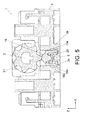
- Said positioning wheel 18 comprises a central protuberance 22 which is able to fit into cavities between every two cogs of the manoeuvring organ 21, said positioning wheel 18 being displaceable linearly within the base 19 between a coupling position, wherein it is fixed between two cogs by means of the release force of the elastic means 20, and an uncoupling position (see figure 5 ), wherein it is pushed by one of the cogs compressing the elastic means 20, depending on the rotational position of the rotating control shaft 2.
- the positioning wheel 18 includes two pins 23 substantially parallel to the direction of displacement Z of said wheel 18 within in the base 19.
- the positioning wheel 18 is therefore capable of sliding along the toothed surface of the rotating manoeuvre organ 21, while the elastic means 20 always keep the surface of the positioning wheel 18 in contact with the surface of the corresponding cog of the rotating manoeuvre organ 21.
- the positioning wheel 18 includes displacement guiding means of said wheel, which include first guiding surfaces 18a at each lateral end intended to slide, respectively, on first walls 19a of the base 19, and second guiding surfaces 23a at each lateral end of the pins 23 intended to slide, respectively, on second walls 19b of the base 19.
- the guiding surfaces 18a, 23a of the wheel 18 prevent said wheel 18 from rocking in its housing along either of the two axes X and Y, perpendicular to the linear direction of displacement Z of the wheel 19.
- the guiding surfaces 18a, 23a of the wheel 18 slide, respectively, on the lateral walls 19a, 19b of the base 19 so that their linear displacement is performed with minimal lateral play due to the fact that the wheel 18, during the movement thereof, is always housed within said lateral guiding walls 19a, 19b of the base 19, even in resting position.
- the positioning wheel 18 includes retaining means of said positioning wheel within the base 19, which include retaining hooks 24 at both lateral ends of the pins 23 intended to make contact, respectively, with stop surfaces 19c of the base 19, said wheel 18 remaining retained within the base 19 during the assembly thereof prior to the placing of the rotating manoeuvre organ 21 and other components of the switch 1.
- the hooks 24 of the wheel 18, by sliding inside the base 19, keep said wheel 18 held in place during specific assembly stages, thanks to the stopping action of said hooks 24 with said stop surface 19c facing the base 19.
- This geometry of the positioning wheel 18 is what makes it possible for said wheel 18 to be held within the base 19, forming independent sub-arrays, which can be assembled regardless of the final assembly of the switch 1 in specific optimised systems.
- the elastic means 20 comprise a compression spring coupled at one end to the positioning wheel 18 and housed at its other end in the base 19.
- the guiding means of the positioning wheel 18, apart from eliminating the radial play of the manoeuvring organ 21, permit the optimisation of the force of the elastic means 20, which directly leads to the optimisation of the rotational torque of the rotating manoeuvre organ 21.
Landscapes
- Rotary Switch, Piano Key Switch, And Lever Switch (AREA)
Claims (13)
- Drehschalter (1) für elektrische Geräte oder dergleichen, der eine sich drehende Steuerwelle (2) aufweist, die drehbar an einem Rahmen (3) angebracht ist, wobei die sich drehende Steuerwelle (2) mit einer Mehrzahl von Nockenscheiben (4) versehen ist, die jeweils einer einer Mehrzahl von Stromabschaltvorrichtungen (5) zugeordnet sind, wobei jede Stromabschaltvorrichtung (5) einer Nockenscheibe (4) zugewandt ist und in einer auf den Rahmen (3) bezogenen Basis (6) untergebracht ist und in der Basis (6) zwischen einer verbundenen Position und einer getrennten Position eines Paares elektrischer Verbindungsstreifen (7), die einstückig an den Rahmen (3) angefügt sind, linear verschiebbar ist, so dass jede Nockenscheibe (4) in Abhängigkeit von der Drehposition der sich drehenden Steuerwelle (2) in der Lage ist, die Stromabschaltvorrichtung (5) zu verbinden oder zu trennen, und eine Positionierungsvorrichtung (8) der sich drehenden Steuerwelle (2) aufweist, die in der Lage ist, eine Serie voreingestellter radialer Positionen, die verschiedenen Funktionen des Schalters (1) zugeordnet sind, zu definieren, dadurch gekennzeichnet, dass jede Stromabschaltvorrichtung (5) eine mobile Brückenanordnung (9), die mit einem an einer elastischen Einrichtung (11) angebrachten Kunststoffträger (10) versehen ist, und eine mit dem Kunststoffträger (10) gekoppelte Metallbrücke (12) aufweist, wobei die Metallbrücke (12) in der Lage ist, anhand der Freigabekraft der elastischen Einrichtung (11) in der verbundenen Position einen direkten Kontakt mit den jeweiligen Streifen (7) aufrechtzuerhalten und sich von den Streifen (7) wegzubewegen, wenn die mobile Brückenanordnung (9) seitens der Nockenscheibe (4) gedrückt wird, wobei die elastische Einrichtung (11) in der getrennten Position zusammengedrückt wird.
- Schalter (1) gemäß Anspruch 1, bei dem der Kunststoffträger (10) der mobilen Brückenanordnung (9) einen Kern (13), der mit einer Passeinrichtung (16) zum Koppeln mit der Metallbrücke (12) versehen ist, eine in eine zentrale Zone des Kerns (13), die mit der Nockenscheibe (4) in Kontakt treten soll, integrierte Ausstülpung (14) und zwei Zapfen (15), die im Wesentlichen parallel zu der Verschiebungsrichtung (Z) der mobilen Brückenanordnung (9) in der Basis (6) sind, aufweist.
- Schalter (1) gemäß Anspruch 2, bei dem der Kunststoffträger (10) Führungseinrichtungen (13a, 15a) zum Verschieben der mobilen Brückenanordnung (9) umfasst.
- Schalter (1) gemäß Anspruch 3, bei dem die Führungseinrichtungen des Kunststoffträgers (10) erste Führungsoberflächen (13a) an jedem lateralen Ende des Kerns (13), die jeweils an einer von ersten Wänden (6a) der Basis (6) gleiten sollen, und zweite Führungsoberflächen (15a), die jeweils an einer von zweiten Wänden (6b) der Basis (6) gleiten sollen, umfassen.
- Schalter (1) gemäß Anspruch 2, bei dem der Kunststoffträger (10) eine Einrichtung (17) zum Halten der mobilen Brückenanordnung (9) in der Basis (6) umfasst.
- Schalter (1) gemäß Anspruch 5, bei dem die Halteeinrichtung des Kunststoffträgers (10) Haltehaken (17) an beiden lateralen Enden der Zapfen (15) umfasst, die jeweils mit einer von Anschlagoberflächen (6c) der Basis (6) in Kontakt treten sollen, wobei die Stromabschaltvorrichtung (5) während der Montage derselben vor der Platzierung der Streifen (7) in der Basis (6) gehalten wird.
- Schalter (1) gemäß Anspruch 1, bei dem die elastische Einrichtung (11) eine Druckfeder aufweist, die an einem Ende mit dem Kunststoffträger (10) gekoppelt ist und an dem anderen Ende derselben in der Basis (6) untergebracht ist.
- Schalter (1) gemäß Anspruch 1, bei dem die Positionierungsvorrichtung (8) der sich drehenden Steuerwelle (2) ein Positionierungsrad (18) aufweist, das in einer auf den Rahmen (3) bezogenen Basis (19) untergebracht ist, an einer elastischen Einrichtung (20) angebracht ist und einem sich drehenden Manövrierelement (21) zugewandt ist, das einstückig an die sich drehende Steuerwelle (2) angefügt ist, wobei das Manövrierelement (21) ein gezahntes Profil in der Form einer Ratsche umfasst und das Positionierungsrad (18) eine zentrale Ausstülpung (22) aufweist, die in der Lage ist, in Hohlräume zwischen jedem zweiten Zahn des Manövrierelements (21) zu passen, wobei das Positionierungsrad (18) zwischen einer Kopplungsposition, in der es anhand der Freigabekraft der elastischen Einrichtung (20) zwischen zwei Zähnen befestigt ist, und einer Entkopplungsposition, in der es durch einen der Zähne, der die elastische Einrichtung (20) zusammendrückt, gedrückt wird, in der Basis (19) linear verschiebbar ist, je nach der Drehposition der sich drehenden Steuerwelle (2), und wobei das Positionierungsrad (18) ferner zwei Zapfen (23) aufweist, die im Wesentlichen parallel zu der Verschiebungsrichtung (Z) des Rades (18) in der Basis (19) sind.
- Schalter (1) gemäß Anspruch 8, bei dem das Positionierungsrad (18) Führungseinrichtungen (18a, 23a) zum Verschieben des Rades (18) umfasst.
- Schalter (1) gemäß Anspruch 9, bei dem die Führungseinrichtungen des Positionierungsrades (18) erste Führungsoberflächen (18a) an jedem lateralen Ende, die jeweils an einer von ersten Wänden (19a) der Basis (19) gleiten sollen, und zweite Führungsoberflächen (23a) an jedem lateralen Ende der Zapfen (23), die jeweils an einer von zweiten Wänden (19b) der Basis (19) gleiten sollen, umfassen.
- Schalter (1) gemäß Anspruch 8, bei dem das Positionierungsrad (18) eine Einrichtung (24) zum Halten des Rades (18) in der Basis (19) aufweist.
- Schalter (1) gemäß Anspruch 11, bei dem die Halteeinrichtung des Positionierungsrades (18) Haltehaken (24) an beiden lateralen Enden der Zapfen (23) umfasst, die jeweils mit einer von Anschlagoberflächen (19c) der Basis (19) in Kontakt treten sollen, wobei das Rad (18) während der Montage desselben vor dem Platzieren des sich drehenden Manövrierelements (21) und anderer Komponenten des Schalters (1) in der Basis (19) gehalten bleibt.
- Schalter (1) gemäß Anspruch 8, bei dem die elastische Einrichtung (20) eine Druckfeder aufweist, die an einem Ende mit dem Positionierungsrad (18) gekoppelt ist und an ihrem anderen Ende in der Basis (19) untergebracht ist.
Priority Applications (2)
| Application Number | Priority Date | Filing Date | Title |
|---|---|---|---|
| EP12382153.0A EP2654055B1 (de) | 2012-04-19 | 2012-04-19 | Drehschalter für Haushaltsgeräte oder dergleichen |
| PL12382153T PL2654055T3 (pl) | 2012-04-19 | 2012-04-19 | Przełącznik obrotowy dla urządzeń elektrycznych i tym podobnych |
Applications Claiming Priority (1)
| Application Number | Priority Date | Filing Date | Title |
|---|---|---|---|
| EP12382153.0A EP2654055B1 (de) | 2012-04-19 | 2012-04-19 | Drehschalter für Haushaltsgeräte oder dergleichen |
Publications (2)
| Publication Number | Publication Date |
|---|---|
| EP2654055A1 EP2654055A1 (de) | 2013-10-23 |
| EP2654055B1 true EP2654055B1 (de) | 2015-01-21 |
Family
ID=46201528
Family Applications (1)
| Application Number | Title | Priority Date | Filing Date |
|---|---|---|---|
| EP12382153.0A Active EP2654055B1 (de) | 2012-04-19 | 2012-04-19 | Drehschalter für Haushaltsgeräte oder dergleichen |
Country Status (2)
| Country | Link |
|---|---|
| EP (1) | EP2654055B1 (de) |
| PL (1) | PL2654055T3 (de) |
Cited By (1)
| Publication number | Priority date | Publication date | Assignee | Title |
|---|---|---|---|---|
| EP4463880A4 (de) * | 2022-01-13 | 2025-12-24 | Novateur Electrical & Digital Systems Private Ltd | Schaltanordnung für eine schaltvorrichtung |
Families Citing this family (3)
| Publication number | Priority date | Publication date | Assignee | Title |
|---|---|---|---|---|
| GB2589107A (en) * | 2019-09-05 | 2021-05-26 | Eaton Intelligent Power Ltd | Semi-independent switch-disconnector |
| CN112786336B (zh) * | 2020-12-31 | 2025-07-01 | 广州市玛高电器有限公司 | 用于旋转开关的插脚以及旋转开关 |
| CN113936932B (zh) * | 2021-11-01 | 2024-04-12 | 阳光电源股份有限公司 | 一种逆变器 |
Family Cites Families (2)
| Publication number | Priority date | Publication date | Assignee | Title |
|---|---|---|---|---|
| FR2506508A1 (fr) * | 1981-05-20 | 1982-11-26 | Alsthom Cgee | Element modulaire de contact et commutateur a commande rotative comportant un tel element |
| IT1238322B (it) * | 1990-01-19 | 1993-07-12 | Bremas Spa | Punteria in particolare per la cooperazione con alberi a camme in commutatori elettrici, interruttori o similari |
-
2012
- 2012-04-19 EP EP12382153.0A patent/EP2654055B1/de active Active
- 2012-04-19 PL PL12382153T patent/PL2654055T3/pl unknown
Cited By (1)
| Publication number | Priority date | Publication date | Assignee | Title |
|---|---|---|---|---|
| EP4463880A4 (de) * | 2022-01-13 | 2025-12-24 | Novateur Electrical & Digital Systems Private Ltd | Schaltanordnung für eine schaltvorrichtung |
Also Published As
| Publication number | Publication date |
|---|---|
| EP2654055A1 (de) | 2013-10-23 |
| PL2654055T3 (pl) | 2015-05-29 |
Similar Documents
| Publication | Publication Date | Title |
|---|---|---|
| EP2654055B1 (de) | Drehschalter für Haushaltsgeräte oder dergleichen | |
| EP2599097B1 (de) | Schiebeschalter und thermostatregler damit | |
| WO2013085933A1 (en) | Multi-stage variable resistance trigger | |
| CN101140835A (zh) | 开关以及触点模块 | |
| EP3319107B1 (de) | Druckknopfschalter | |
| US20110168536A1 (en) | Emergency stop device | |
| EP3417466B1 (de) | Druckknopfbetätigter schalter mit knopfausrichtungssystem | |
| CN201421790Y (zh) | 开关按钮结构 | |
| CN110612590B (zh) | 改进的具有形状记忆线材的致动器 | |
| TWM565390U (zh) | 開關裝置改良結構 | |
| EP2993553A1 (de) | Winkeljustierungsmechanismus | |
| AU2017279756B2 (en) | Transmission device for push-button switch, push-button switch and socket | |
| JP6301661B2 (ja) | マルチポジション型往復回転アクチュエータ | |
| CN107112158A (zh) | 开关 | |
| CN210640133U (zh) | 双电源自动转换开关的指示装置和双电源自动转换开关 | |
| EP3093195B1 (de) | Verstelleinheit, rückblickvorrichtung und fahrzeug | |
| CN203503536U (zh) | 一种小角度按键墙壁开关 | |
| CN101620943B (zh) | 开关按钮结构 | |
| US2763739A (en) | Switch | |
| CN104701038B (zh) | 开关装置 | |
| CN202473670U (zh) | 双电源转换开关 | |
| US9064657B2 (en) | Switching unit for an electrical switching device | |
| CN202940154U (zh) | 电动开关 | |
| CN216213092U (zh) | 一种新型隔离开关 | |
| EP2833384B1 (de) | Beweglicher Kontaktpunkt für Schalter |
Legal Events
| Date | Code | Title | Description |
|---|---|---|---|
| PUAI | Public reference made under article 153(3) epc to a published international application that has entered the european phase |
Free format text: ORIGINAL CODE: 0009012 |
|
| AK | Designated contracting states |
Kind code of ref document: A1 Designated state(s): AL AT BE BG CH CY CZ DE DK EE ES FI FR GB GR HR HU IE IS IT LI LT LU LV MC MK MT NL NO PL PT RO RS SE SI SK SM TR |
|
| AX | Request for extension of the european patent |
Extension state: BA ME |
|
| 17P | Request for examination filed |
Effective date: 20140327 |
|
| RBV | Designated contracting states (corrected) |
Designated state(s): AL AT BE BG CH CY CZ DE DK EE ES FI FR GB GR HR HU IE IS IT LI LT LU LV MC MK MT NL NO PL PT RO RS SE SI SK SM TR |
|
| RIC1 | Information provided on ipc code assigned before grant |
Ipc: H01H 3/42 20060101ALN20140807BHEP Ipc: H01H 1/20 20060101AFI20140807BHEP Ipc: H01H 3/50 20060101ALN20140807BHEP Ipc: H01H 19/62 20060101ALI20140807BHEP Ipc: H01H 19/11 20060101ALN20140807BHEP |
|
| GRAP | Despatch of communication of intention to grant a patent |
Free format text: ORIGINAL CODE: EPIDOSNIGR1 |
|
| RIC1 | Information provided on ipc code assigned before grant |
Ipc: H01H 3/42 20060101ALN20140918BHEP Ipc: H01H 19/11 20060101ALN20140918BHEP Ipc: H01H 1/20 20060101AFI20140918BHEP Ipc: H01H 3/50 20060101ALN20140918BHEP Ipc: H01H 19/62 20060101ALI20140918BHEP |
|
| RIC1 | Information provided on ipc code assigned before grant |
Ipc: H01H 19/11 20060101ALN20140923BHEP Ipc: H01H 3/50 20060101ALN20140923BHEP Ipc: H01H 3/42 20060101ALN20140923BHEP Ipc: H01H 19/62 20060101ALI20140923BHEP Ipc: H01H 1/20 20060101AFI20140923BHEP |
|
| INTG | Intention to grant announced |
Effective date: 20141009 |
|
| RIC1 | Information provided on ipc code assigned before grant |
Ipc: H01H 1/20 20060101AFI20140930BHEP Ipc: H01H 19/62 20060101ALI20140930BHEP Ipc: H01H 19/11 20060101ALN20140930BHEP Ipc: H01H 3/42 20060101ALN20140930BHEP Ipc: H01H 3/50 20060101ALN20140930BHEP |
|
| RIN1 | Information on inventor provided before grant (corrected) |
Inventor name: LOPEZ ALCALA-GALIANO, FERNANDO |
|
| GRAS | Grant fee paid |
Free format text: ORIGINAL CODE: EPIDOSNIGR3 |
|
| GRAA | (expected) grant |
Free format text: ORIGINAL CODE: 0009210 |
|
| AK | Designated contracting states |
Kind code of ref document: B1 Designated state(s): AL AT BE BG CH CY CZ DE DK EE ES FI FR GB GR HR HU IE IS IT LI LT LU LV MC MK MT NL NO PL PT RO RS SE SI SK SM TR |
|
| REG | Reference to a national code |
Ref country code: GB Ref legal event code: FG4D |
|
| REG | Reference to a national code |
Ref country code: CH Ref legal event code: EP |
|
| REG | Reference to a national code |
Ref country code: IE Ref legal event code: FG4D |
|
| REG | Reference to a national code |
Ref country code: DE Ref legal event code: R096 Ref document number: 602012005037 Country of ref document: DE Effective date: 20150305 |
|
| REG | Reference to a national code |
Ref country code: AT Ref legal event code: REF Ref document number: 709496 Country of ref document: AT Kind code of ref document: T Effective date: 20150315 |
|
| REG | Reference to a national code |
Ref country code: PL Ref legal event code: T3 |
|
| REG | Reference to a national code |
Ref country code: NL Ref legal event code: VDEP Effective date: 20150121 |
|
| REG | Reference to a national code |
Ref country code: AT Ref legal event code: MK05 Ref document number: 709496 Country of ref document: AT Kind code of ref document: T Effective date: 20150121 |
|
| REG | Reference to a national code |
Ref country code: LT Ref legal event code: MG4D |
|
| PG25 | Lapsed in a contracting state [announced via postgrant information from national office to epo] |
Ref country code: NO Free format text: LAPSE BECAUSE OF FAILURE TO SUBMIT A TRANSLATION OF THE DESCRIPTION OR TO PAY THE FEE WITHIN THE PRESCRIBED TIME-LIMIT Effective date: 20150421 Ref country code: ES Free format text: LAPSE BECAUSE OF FAILURE TO SUBMIT A TRANSLATION OF THE DESCRIPTION OR TO PAY THE FEE WITHIN THE PRESCRIBED TIME-LIMIT Effective date: 20150121 Ref country code: SE Free format text: LAPSE BECAUSE OF FAILURE TO SUBMIT A TRANSLATION OF THE DESCRIPTION OR TO PAY THE FEE WITHIN THE PRESCRIBED TIME-LIMIT Effective date: 20150121 Ref country code: FI Free format text: LAPSE BECAUSE OF FAILURE TO SUBMIT A TRANSLATION OF THE DESCRIPTION OR TO PAY THE FEE WITHIN THE PRESCRIBED TIME-LIMIT Effective date: 20150121 Ref country code: LT Free format text: LAPSE BECAUSE OF FAILURE TO SUBMIT A TRANSLATION OF THE DESCRIPTION OR TO PAY THE FEE WITHIN THE PRESCRIBED TIME-LIMIT Effective date: 20150121 Ref country code: HR Free format text: LAPSE BECAUSE OF FAILURE TO SUBMIT A TRANSLATION OF THE DESCRIPTION OR TO PAY THE FEE WITHIN THE PRESCRIBED TIME-LIMIT Effective date: 20150121 Ref country code: BG Free format text: LAPSE BECAUSE OF FAILURE TO SUBMIT A TRANSLATION OF THE DESCRIPTION OR TO PAY THE FEE WITHIN THE PRESCRIBED TIME-LIMIT Effective date: 20150421 |
|
| PG25 | Lapsed in a contracting state [announced via postgrant information from national office to epo] |
Ref country code: NL Free format text: LAPSE BECAUSE OF FAILURE TO SUBMIT A TRANSLATION OF THE DESCRIPTION OR TO PAY THE FEE WITHIN THE PRESCRIBED TIME-LIMIT Effective date: 20150121 Ref country code: AT Free format text: LAPSE BECAUSE OF FAILURE TO SUBMIT A TRANSLATION OF THE DESCRIPTION OR TO PAY THE FEE WITHIN THE PRESCRIBED TIME-LIMIT Effective date: 20150121 Ref country code: IS Free format text: LAPSE BECAUSE OF FAILURE TO SUBMIT A TRANSLATION OF THE DESCRIPTION OR TO PAY THE FEE WITHIN THE PRESCRIBED TIME-LIMIT Effective date: 20150521 Ref country code: LV Free format text: LAPSE BECAUSE OF FAILURE TO SUBMIT A TRANSLATION OF THE DESCRIPTION OR TO PAY THE FEE WITHIN THE PRESCRIBED TIME-LIMIT Effective date: 20150121 Ref country code: GR Free format text: LAPSE BECAUSE OF FAILURE TO SUBMIT A TRANSLATION OF THE DESCRIPTION OR TO PAY THE FEE WITHIN THE PRESCRIBED TIME-LIMIT Effective date: 20150422 Ref country code: RS Free format text: LAPSE BECAUSE OF FAILURE TO SUBMIT A TRANSLATION OF THE DESCRIPTION OR TO PAY THE FEE WITHIN THE PRESCRIBED TIME-LIMIT Effective date: 20150121 |
|
| REG | Reference to a national code |
Ref country code: DE Ref legal event code: R097 Ref document number: 602012005037 Country of ref document: DE |
|
| PG25 | Lapsed in a contracting state [announced via postgrant information from national office to epo] |
Ref country code: SK Free format text: LAPSE BECAUSE OF FAILURE TO SUBMIT A TRANSLATION OF THE DESCRIPTION OR TO PAY THE FEE WITHIN THE PRESCRIBED TIME-LIMIT Effective date: 20150121 Ref country code: EE Free format text: LAPSE BECAUSE OF FAILURE TO SUBMIT A TRANSLATION OF THE DESCRIPTION OR TO PAY THE FEE WITHIN THE PRESCRIBED TIME-LIMIT Effective date: 20150121 Ref country code: RO Free format text: LAPSE BECAUSE OF FAILURE TO SUBMIT A TRANSLATION OF THE DESCRIPTION OR TO PAY THE FEE WITHIN THE PRESCRIBED TIME-LIMIT Effective date: 20150121 Ref country code: DK Free format text: LAPSE BECAUSE OF FAILURE TO SUBMIT A TRANSLATION OF THE DESCRIPTION OR TO PAY THE FEE WITHIN THE PRESCRIBED TIME-LIMIT Effective date: 20150121 Ref country code: CZ Free format text: LAPSE BECAUSE OF FAILURE TO SUBMIT A TRANSLATION OF THE DESCRIPTION OR TO PAY THE FEE WITHIN THE PRESCRIBED TIME-LIMIT Effective date: 20150121 |
|
| PLBE | No opposition filed within time limit |
Free format text: ORIGINAL CODE: 0009261 |
|
| STAA | Information on the status of an ep patent application or granted ep patent |
Free format text: STATUS: NO OPPOSITION FILED WITHIN TIME LIMIT |
|
| PG25 | Lapsed in a contracting state [announced via postgrant information from national office to epo] |
Ref country code: MC Free format text: LAPSE BECAUSE OF FAILURE TO SUBMIT A TRANSLATION OF THE DESCRIPTION OR TO PAY THE FEE WITHIN THE PRESCRIBED TIME-LIMIT Effective date: 20150121 Ref country code: LU Free format text: LAPSE BECAUSE OF FAILURE TO SUBMIT A TRANSLATION OF THE DESCRIPTION OR TO PAY THE FEE WITHIN THE PRESCRIBED TIME-LIMIT Effective date: 20150419 |
|
| REG | Reference to a national code |
Ref country code: CH Ref legal event code: PL |
|
| 26N | No opposition filed |
Effective date: 20151022 |
|
| REG | Reference to a national code |
Ref country code: IE Ref legal event code: MM4A |
|
| PG25 | Lapsed in a contracting state [announced via postgrant information from national office to epo] |
Ref country code: CH Free format text: LAPSE BECAUSE OF NON-PAYMENT OF DUE FEES Effective date: 20150430 Ref country code: LI Free format text: LAPSE BECAUSE OF NON-PAYMENT OF DUE FEES Effective date: 20150430 |
|
| REG | Reference to a national code |
Ref country code: FR Ref legal event code: ST Effective date: 20151231 |
|
| PG25 | Lapsed in a contracting state [announced via postgrant information from national office to epo] |
Ref country code: FR Free format text: LAPSE BECAUSE OF NON-PAYMENT OF DUE FEES Effective date: 20150430 Ref country code: SI Free format text: LAPSE BECAUSE OF FAILURE TO SUBMIT A TRANSLATION OF THE DESCRIPTION OR TO PAY THE FEE WITHIN THE PRESCRIBED TIME-LIMIT Effective date: 20150121 |
|
| PG25 | Lapsed in a contracting state [announced via postgrant information from national office to epo] |
Ref country code: IE Free format text: LAPSE BECAUSE OF NON-PAYMENT OF DUE FEES Effective date: 20150419 |
|
| PG25 | Lapsed in a contracting state [announced via postgrant information from national office to epo] |
Ref country code: BE Free format text: LAPSE BECAUSE OF FAILURE TO SUBMIT A TRANSLATION OF THE DESCRIPTION OR TO PAY THE FEE WITHIN THE PRESCRIBED TIME-LIMIT Effective date: 20150121 |
|
| GBPC | Gb: european patent ceased through non-payment of renewal fee |
Effective date: 20160419 |
|
| PG25 | Lapsed in a contracting state [announced via postgrant information from national office to epo] |
Ref country code: MT Free format text: LAPSE BECAUSE OF FAILURE TO SUBMIT A TRANSLATION OF THE DESCRIPTION OR TO PAY THE FEE WITHIN THE PRESCRIBED TIME-LIMIT Effective date: 20150121 |
|
| PG25 | Lapsed in a contracting state [announced via postgrant information from national office to epo] |
Ref country code: GB Free format text: LAPSE BECAUSE OF NON-PAYMENT OF DUE FEES Effective date: 20160419 |
|
| PG25 | Lapsed in a contracting state [announced via postgrant information from national office to epo] |
Ref country code: HU Free format text: LAPSE BECAUSE OF FAILURE TO SUBMIT A TRANSLATION OF THE DESCRIPTION OR TO PAY THE FEE WITHIN THE PRESCRIBED TIME-LIMIT; INVALID AB INITIO Effective date: 20120419 Ref country code: SM Free format text: LAPSE BECAUSE OF FAILURE TO SUBMIT A TRANSLATION OF THE DESCRIPTION OR TO PAY THE FEE WITHIN THE PRESCRIBED TIME-LIMIT Effective date: 20150121 |
|
| PG25 | Lapsed in a contracting state [announced via postgrant information from national office to epo] |
Ref country code: CY Free format text: LAPSE BECAUSE OF FAILURE TO SUBMIT A TRANSLATION OF THE DESCRIPTION OR TO PAY THE FEE WITHIN THE PRESCRIBED TIME-LIMIT Effective date: 20150121 |
|
| PG25 | Lapsed in a contracting state [announced via postgrant information from national office to epo] |
Ref country code: PT Free format text: LAPSE BECAUSE OF FAILURE TO SUBMIT A TRANSLATION OF THE DESCRIPTION OR TO PAY THE FEE WITHIN THE PRESCRIBED TIME-LIMIT Effective date: 20150521 |
|
| PG25 | Lapsed in a contracting state [announced via postgrant information from national office to epo] |
Ref country code: MK Free format text: LAPSE BECAUSE OF FAILURE TO SUBMIT A TRANSLATION OF THE DESCRIPTION OR TO PAY THE FEE WITHIN THE PRESCRIBED TIME-LIMIT Effective date: 20150121 |
|
| PG25 | Lapsed in a contracting state [announced via postgrant information from national office to epo] |
Ref country code: AL Free format text: LAPSE BECAUSE OF FAILURE TO SUBMIT A TRANSLATION OF THE DESCRIPTION OR TO PAY THE FEE WITHIN THE PRESCRIBED TIME-LIMIT Effective date: 20150121 |
|
| PGFP | Annual fee paid to national office [announced via postgrant information from national office to epo] |
Ref country code: PL Payment date: 20230313 Year of fee payment: 12 Ref country code: IT Payment date: 20230310 Year of fee payment: 12 |
|
| P01 | Opt-out of the competence of the unified patent court (upc) registered |
Effective date: 20230420 |
|
| PGFP | Annual fee paid to national office [announced via postgrant information from national office to epo] |
Ref country code: DE Payment date: 20230307 Year of fee payment: 12 |
|
| PGFP | Annual fee paid to national office [announced via postgrant information from national office to epo] |
Ref country code: TR Payment date: 20230417 Year of fee payment: 12 |
|
| REG | Reference to a national code |
Ref country code: DE Ref legal event code: R119 Ref document number: 602012005037 Country of ref document: DE |
|
| PG25 | Lapsed in a contracting state [announced via postgrant information from national office to epo] |
Ref country code: DE Free format text: LAPSE BECAUSE OF NON-PAYMENT OF DUE FEES Effective date: 20241105 |
|
| PG25 | Lapsed in a contracting state [announced via postgrant information from national office to epo] |
Ref country code: DE Free format text: LAPSE BECAUSE OF NON-PAYMENT OF DUE FEES Effective date: 20241105 |
|
| PG25 | Lapsed in a contracting state [announced via postgrant information from national office to epo] |
Ref country code: IT Free format text: LAPSE BECAUSE OF NON-PAYMENT OF DUE FEES Effective date: 20240419 |
|
| PG25 | Lapsed in a contracting state [announced via postgrant information from national office to epo] |
Ref country code: PL Free format text: LAPSE BECAUSE OF NON-PAYMENT OF DUE FEES Effective date: 20240419 |