EP2654331A1 - Verfahren und Vorrichtung zur Verwendung bei der Kommunikationsunterstützung über erste und zweite drahtlose Verbindungen eines drahtlosen Sende-Empfangsgerätes - Google Patents
Verfahren und Vorrichtung zur Verwendung bei der Kommunikationsunterstützung über erste und zweite drahtlose Verbindungen eines drahtlosen Sende-Empfangsgerätes Download PDFInfo
- Publication number
- EP2654331A1 EP2654331A1 EP12164555.0A EP12164555A EP2654331A1 EP 2654331 A1 EP2654331 A1 EP 2654331A1 EP 12164555 A EP12164555 A EP 12164555A EP 2654331 A1 EP2654331 A1 EP 2654331A1
- Authority
- EP
- European Patent Office
- Prior art keywords
- wireless
- wireless transceiver
- transceiver
- connection
- wireless device
- Prior art date
- Legal status (The legal status is an assumption and is not a legal conclusion. Google has not performed a legal analysis and makes no representation as to the accuracy of the status listed.)
- Granted
Links
Images





Classifications
-
- H—ELECTRICITY
- H04—ELECTRIC COMMUNICATION TECHNIQUE
- H04W—WIRELESS COMMUNICATION NETWORKS
- H04W8/00—Network data management
- H04W8/26—Network addressing or numbering for mobility support
-
- H—ELECTRICITY
- H04—ELECTRIC COMMUNICATION TECHNIQUE
- H04W—WIRELESS COMMUNICATION NETWORKS
- H04W88/00—Devices specially adapted for wireless communication networks, e.g. terminals, base stations or access point devices
- H04W88/02—Terminal devices
- H04W88/06—Terminal devices adapted for operation in multiple networks or having at least two operational modes, e.g. multi-mode terminals
Definitions
- a wireless communication device such as a portable battery-powered wireless telephony device, may be configured to communicate in wireless communication networks.
- a device may communicate via access points (APs) of wireless local area networks (WLANs) in accordance with IEEE 802.11 standards or the like.
- APs access points
- WLANs wireless local area networks
- Such devices may also communicate using peer-to-peer communication techniques, for example, in accordance with the Wi-Fi Peer-To-Peer (P2P) Technical specification, and/or be certified as a "Wi-Fi Direct" device,
- Wireless device 201 may also operate for communications in other different wireless networks, such as a wireless network 122 which is also a WLAN.
- wireless network 122 is a private communication network of an enterprise (e.g. an organization, a company, a corporation, etc.) of wireless device 201. Similar to wireless network 104, wireless network 122 has a plurality of wireless APs 128, 130 and 132, one or more servers 124, and a gateway 126.
- gateway 126 may be configured to permit or deny access to the data, applications, and/or functionality offered via wireless network 122 depending on whether or not a device has been authorized and what access rights are given upon authorization.
- gateway 126 is configured to permit or deny internal access to the data, applications, and/or functionality in wireless network 122.
- wireless device 201 may be configured in accordance with one or more cellular telecommunication standards, such as Global Systems for Mobile (GSM) and/or General Packet Radio Service (GPRS) technologies.
- GSM Global Systems for Mobile
- GPRS General Packet Radio Service
- such wireless device may additionally or alternatively operate in accordance with other such cellular standards, such as Enhanced Data rates for GSM Evolution (EDGE) or Enhanced GPRS (EGPRS), Universal Mobile Telecommunications System (UMTS), Long-Term Evolution (LTE), or EVolution-Data Only (EV-DO) (for CDMA) technologies, as a few examples.
- GSM Global Systems for Mobile
- GPRS General Packet Radio Service
- EDGE Enhanced Data rates for GSM Evolution
- EEGPRS Universal Mobile Telecommunications System
- LTE Long-Term Evolution
- EV-DO EVolution-Data Only
- data may be communicated directly between the wireless devices without the data traversing any wireless network infrastructure, where one of the devices is set to operate or serve as an AP (switching operation from as an end terminal) and the other device operates as an end terminal to associate and connect with the AP (i.e. wireless device 201 operating as an AP) for communications.
- Wireless device 201 may operate such that, when in the AP mode of operation with other communication devices 195 and 197, it also operates as a client with another AP.
- wireless device 201 may communicate with any one of a plurality of stations or access points (APs) of wireless network 104 within its geographic coverage area.
- Wireless device 201 may send and receive communication signals over wireless network 104 after the required network registration or activation procedures have been completed.
- Signals received by the antenna 214 through wireless network 104 are input to the receiver 212, which may perform such common receiver functions as signal amplification, frequency down conversion, filtering, channel selection, etc., as well as analog-to-digital (A/D) conversion.
- A/D conversion of a received signal allows more complex communication functions such as demodulation and decoding to be performed in the DSP 217.
- An orientation sensor 251 may generate orientation data which specifies the orientation of wireless device 201.
- the orientation data in at least some example embodiments, specifies the orientation of the device 201 relative to the gravitational field of the earth.
- Wireless device 201 may, in at least some example embodiments, include a near field communications (NFC) subsystem 265.
- the NFC subsystem 265 is configured to communicate with other wireless devices 201 and/or tags, using an NFC communications protocol.
- NFC is a set of short-range wireless technologies which typically require a distance of 4 cm or less for communications.
- the NFC subsystem 265 may include an NFC chip and an NFC antenna.
- the first speaker may be located at one side of the display 204 and the second speaker may be located at another side of the display which is opposite the side of the display where the first speaker is located.
- the first speaker may be disposed at a left side of the display and the second speaker may be disposed at a right side of the display.
- each speaker 256 may be associated with a separate audio channel.
- the multiple speakers may, for example, be used to provide stereophonic sound (which may also be referred to as stereo).
- Wireless device 201 may also include one or more cameras 253.
- the one or more cameras 253 may be capable of capturing images in the form of still photographs or motion video.
- wireless device 201 includes a front facing camera 253.
- a front facing camera is a camera which is generally located on a front face of wireless device 201.
- the front face is typically the face on which a display 204 is mounted. That is, the display 204 is configured to display content which may be viewed from a side of wireless device 201 where the camera 253 is directed.
- the front facing camera 253 may be located anywhere on the front surface of the electronic device; for example, the camera 253 may be located above or below the display 204.
- wireless device 201 includes an electromagnetic (EM) radiation source 257.
- the EM radiation source 257 is configured to emit electromagnetic radiation from the side of the electronic device which is associated with a camera 253 of that wireless device 201.
- the camera is a front facing camera 253
- wireless device 201 may be configured to emit electromagnetic radiation from the front face of wireless device 201.
- the electromagnetic radiation source 257 is configured to emit radiation in a direction which may visible by the camera. That is, the camera 253 and the electromagnetic radiation source 257 may be disposed on wireless device 201 so that electromagnetic radiation emitted by the electromagnetic radiation source 257 is visible in images obtained by the camera.
- the electromagnetic radiation source 257 may be an infrared (IR) radiation source which is configured to emit infrared radiation. In at least some example embodiments, the electromagnetic radiation source 257 may be configured to emit radiation which is not part of the visible spectrum.
- the camera 253 may be a camera which is configured to capture radiation of the type emitted by the electromagnetic radiation source 257. Accordingly, in at least some example embodiments, the camera 253 is configured to capture at least some electromagnetic radiation which is not in the visible spectrum.
- Wireless device 201 also includes a battery 238 as a power source, which is typically one or more rechargeable batteries that may be charged for example, through charging circuitry coupled to a battery interface 236 such as the data port 252.
- the battery 238 provides electrical power to at least some of the electrical circuitry in wireless device 201, and the battery interface 236 provides a mechanical and electrical connection for the battery 238.
- the battery interface 236 is coupled to a regulator (not shown) which provides a regulated voltage V to the circuitry for powering wireless device 201.
- Wireless device 201 stores data 227 in an erasable persistent memory, which in one example embodiment is the flash memory 244.
- the data 227 includes service data including information required by wireless device 201 to establish and maintain communication with wireless network 104.
- the data 227 may also include user application data such as email messages, address book and contact information, calendar and schedule information, notepad documents, image files, and other commonly stored user information stored on wireless device 201 by its user, and other data.
- the data 227 stored in the persistent memory (e.g. flash memory 244) of wireless device 201 may be organized, at least partially, into one or more databases or data stores.
- the databases or data stores may contain data items of the same data type or associated with the same application. For example, email messages, contact records, and task items may be stored in individual databases within the device memory.
- the software applications 225 on wireless device 201 may also include a range of additional applications, including for example, a notepad application, Internet browser application, voice communication (i.e. telephony) application, mapping application, or a media player application, or any combination thereof.
- Each of the software applications 225 may include layout information defining the placement of particular fields and graphic elements (e.g. text fields, input fields, icons, etc.) in the user interface (e.g. the display 204) according to the application.
- the software modules 221 or parts thereof may be temporarily loaded into volatile memory such as the RAM 246.
- the RAM 246 is used for storing runtime data variables and other types of data or information, as will be apparent to those skilled in the art. Although specific functions are described for various types of memory, this is merely one example, and those skilled in the art will appreciate that a different assignment of functions to types of memory could also be used.
- a predetermined set of applications that control basic device operations, including data and possibly voice communication applications will normally be installed on wireless device 201 during or after manufacture. Additional applications and/or upgrades to the operating system 223 or software applications 225 may also be loaded onto wireless device 201 through wireless network 104, the auxiliary I/O subsystem 250, the data port 252, the short-range communication subsystem 262, or other suitable subsystem 264.
- the downloaded programs or code modules may be permanently installed; for example, written into the program memory (i.e. the flash memory 244), or written into and executed from the RAM 246 for execution by the processor 240 at runtime.
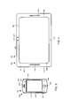
- Example Smartphone Electronic Device Referring now to FIG. 3 , a front view of an example wireless device 201 which is a smartphone 100 is illustrated.
- the smartphone 100 is a mobile phone which offers more advanced computing capability than a basic non-smartphone cellular phone.
- the smartphone 100 may have the ability to execute third party applications which are stored on the smartphone.
- the smartphone 100 may include the components discussed above with reference to FIG. 2 or a subset of those components.
- the smartphone 100 includes a housing 294 which houses at least some of the components discussed above with reference to FIG. 2 .
- the smartphone 100 of FIG. 3 includes a single speaker 256
- the smartphone 100 may include a greater number of speakers 256.
- the smartphone 100 may include a second speaker 256 which is disposed vertically below the display 204 when the smartphone is held in a portrait orientation where its height is longer than its width (i.e. the orientation illustrated in FIG. 3 ).
- the example smartphone 100 also includes a front facing camera 253 which may be located vertically above the display 204 when the smartphone 100 is held in a portrait orientation where its height is longer than its width.
- the front facing camera 253 is located so that it may capture images of objects which are located in front of and/or surrounding the front side of the smartphone 100.
- Tablet computer 300 includes a display 304, which may be a touchscreen display which acts as an input interface 206.
- the display 304 is disposed within tablet computer 300 so that it is viewable at a front side 302 of tablet computer 300. That is, a viewable side of the display 304 is disposed on the front side 302 of tablet computer 300.
- the display 304 is framed by the housing 394, with use of a frame 312 which surrounds the display 304.
- the frame 312 is portion of the housing 394 which provides a border around the display 304.
- the frame 312 is an active frame 312. That is, the frame has a touch sensitive overlay which allows wireless device 201 to detect a touch applied to the frame, thereby allowing the frame 312 to act as an input interface 206 (of FIG. 1 ).
- the example tablet computer 300 also includes a microphone 258.
- the microphone 258 is vertically disposed below the display 304 when the tablet computer is held in the landscape orientation illustrated in FIG. 4 .
- the microphone 258 may be located in other locations in other example embodiments.
- any suitable wireless communication device or terminal may be part of the methods and apparatus which will be described in fuller detail below.
- the wireless network may be a WiMAX-based network (i.e. IEEE 802.16), or an Ultra-WideBand (UWB)-based network (i.e. IEEE 802.15), as a few examples.
- wireless device 201 may establish a Wi-Fi P2P wireless network connection with a tablet 514 which includes a wireless transceiver 512.
- a tablet was previously shown and described in relation to FIG. 4 .
- Such Wi-Fi P2P wireless network connection may be suitable for an applications such as, for example, a "bridge” or “bridging” application, where wireless device 201 is further configured for cellular telecommunications (e.g. equipped with a cellular transceiver) but tablet 514 is not.
- tablet 514 is able to achieve external network (e.g. Internet) connectivity, being connected to wireless device 201 for communications via the cellular telecommunication network.
- external network e.g. Internet
- wireless device 201 When wireless device 201 is connected as such, using one or more Wi-Fi P2P wireless network connections, data may be communicated "directly" between wireless device 201 and the other devices (i.e. without the data traversing any fixed wireless network infrastructure).
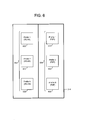
- wireless device 201 has different types of applications stored therein. These applications may include, as examples, a messaging application, a voice telephony application, a Web browsing application, a streaming media application, a file sharing application, a game application, a printer application, a facsimile application, a display or presentation application, a military application, as examples. Wireless device 201 is optimized to establish the appropriate wireless networks based on which type of application is invoked.
- Each one of profiles 602 is associated with a particular WLAN infrastructure network, and includes a plurality of parameters and/or properties for accessing the particular WLAN.
- the WLAN information may include an identification which identifies the WLAN to access (e.g. a SSID or ESSID).
- the WLAN information may also include authentication and/or security information for obtaining access to the WLAN (e.g. a network key, passkey, security key, etc.).
- One of the WLANs appropriate WLAN from profiles 602 will be selected for communication when available, as prioritized in a prioritized list of the profiles 602.
- the wireless device When not connected in a WLAN, the wireless device normally operates to search for WLANs identified in its stored profiles 602. Conversely, the wireless device normally refrains from searching for and communicating in WLANs other than those WLANs identified in stored profiles 602.
- each one of profiles 604 is associated with one of the applications and/or services which utilizes a particular type and/or configuration of Wi-Fi P2P wireless network (or Wi-Fi Direct network).
- Each one of profiles 604 includes parameters and/or properties associated with establishing the particular type and/or configuration of Wi-Fi P2P wireless network for the application and/or service.
- Profiles 604 may be created, viewed, updated, enabled, and disabled, as described in the present disclosure (see e.g. discussion in relation to FIG. 10 ).
- Properties in profiles 604 may additionally or alternatively include a service type property which indicates a service type which identifies the service associated with the device.
- the service types may be or include the appropriate service types as described in the Wi-Fi Peer-To-Peer (P2P) Technical specification (e.g. in Annex E thereof). Examples of such types are as follows: a file sharing service, or a printing service. Alternatively, examples of such types are as follows: Apple File Sharing (AFP) service (or AFP over TCP service), or IP Printing (IPP) Bonjour service.
- AFP Apple File Sharing
- IPP IP Printing
- Properties in profiles 604 may additionally or alternatively include a discovery mode property which indicates a mode utilized for the discovery of devices for the Wi-Fi P2P wireless network connection.
- the discovery mode property may be set to one of the following: a triggered mode of discovery, or a periodic mode of discovery.
- the discovery mode may be set to one of the following: a triggered mode of discovery, a periodic mode of discovery, or a Group Owner (GO) mode of discovery.
- Properties in profiles 604 may additionally or alternatively include a persistent property or indication which indicates whether or not the Wi-Fi P2P wireless network is persistent. If the network is persistent, when an application is opened or activated, the wireless device connects to a previously-established Wi-Fi P2P wireless network.
- Properties in profiles 604 may additionally or alternatively include a coexistence indication or property which indicates whether the Wi-Fi P2P wireless network connection associated with this profile may be maintained while the wireless device operates as a client in an infrastructure network. Properties may additionally or alternatively include another coexistence indication or property which indicates whether the Wi-Fi P2P wireless network connection associated with this profile may be maintained while maintaining another Wi-Fi P2P wireless network connection.
- properties in profiles 604 may omit a device identifier which identifies any particular device for connection, and/or may omit a wireless network identifier which identifies any particular wireless network for connection. Rather, properties in at least some of profiles 604 indicate connection with particular types of devices (and/or services), and/or indicate connection with particular types of networks, as opposed to specifically identified devices, or specifically identified networks.
- Wi-Fi P2P wireless networking lend themselves to different modes of operation. For example, if a wireless device supports a network gateway feature (e.g. a mobile hotspot or MHO feature), then the wireless device may be configured to establish a persistent Wi-Fi P2P wireless network when the service is enabled. As another example, the same wireless device may require a printer service to allow an application to print a document. In this case, the Wi-Fi P2P wireless network may be established on-demand based on an application trigger. In another example, a social networking application may periodically search for other communication devices running the same social networking application, which may result in the wireless device operating in a periodic discovery mode for other devices which advertise the same service.
- a network gateway feature e.g. a mobile hotspot or MHO feature
- profiles associated with the various application/services utilizing Wi-Fi P2P wireless networks are created and stored on the wireless device. These profiles are enabled when needed, such as enabled in response to an activation of an application associated therewith. Further, the profiles may be enabled concurrently.
- the profiles may have data structures defined for compatibility with the Wi-Fi Peer-To-Peer (P2P) Technical specification.
- Each profile may include information specific to Wi-Fi P2P wireless network operation, including device discovery behavior, service discovery options, co-existence with infrastructure connectivity, as well as operational characteristics of the network (e.g. whether it is persistent, or triggered on application launch).
- profiles may be provisioned as defaults in the wireless device, and/or may be configured by applications when installed. Further, the profiles may be configured via the user interface of the wireless device with use of a human-machine interface (HMI) application that provides management of the profiles.
- HMI human-machine interface
- This HMI application may be configured to provide the ability to search for and identify any Wi-Fi P2P wireless networks.
- the profiles are used to manage the behavior of the WLAN or Wi-Fi driver of the wireless device to accommodate for the various application/services.
- the driver may be configured to support each particular use case. More particularly, the driver may use the profile information to manage peer-to-peer communications on the wireless device, as well as to arbitrate between Wi-Fi P2P wireless network and other modes of connectivity (e.g. infrastructure STA mode).
- the driver may be further configured to support other application requirements, such as sleep modes, discovery modes, and/or co-existence with an infrastructure network connection over WLAN, etc.
- An example set of properties and/or parameters relating to the behavioral characteristics were provided earlier above.
- FIG. 7 illustrates that wireless device 201 may operate as a P2P concurrent device in accordance with the Wi-Fi Peer-To-Peer (P2P) Technical specification.
- wireless device 201 has a first MAC entity 902 operating as a "WLAN-STA" and a second MAC entity 904 operating as a "P2P Device".
- Dual MAC functionality may be implemented as, for example, two virtual MAC entities over one physical layer (PHY) entity.
- PHY physical layer
- wireless device 201 may operate to concurrently maintain two different types of wireless connections via the same wireless transceiver or PHY entity.
- wireless device 201 may only have a single Media Access Control (MAC) address assigned to the wireless transceiver for identifying communications to and from wireless device 201.
- MAC Media Access Control
- P2P Device addressing shall have a P2P Device Address, conforming to the format as described in ⁇ 7.1.3.3.1 of IEEE Std 802.11-2007 [1], which is used to uniquely reference that P2P Device.
- the P2P Device Address of a P2P Device shall be its globally administered MAC address, or its globally administered MAC address with the locally administered bit set.
- the P2P Device Address shall be used as the receiver address (RA) for all frames sent to a P2P Device during P2P Discovery, with the sole exception of using a broadcast receiver address in a Probe Request.
- the P2P Device Address shall be used as the transmitter address (TA) for all frames sent by a P2P Device during P2P Discovery.”
- the original IEEE 802 MAC address utilizes MAC-48.
- MAC-48 there are 2 48 (i.e., 281,474,976,710,656) possible MAC addresses.
- the 48-bit code of the MAC address is divided into 12 hex digits.
- the hexadecimal notation is used at least to differentiate it from IP addresses that use decimal notation.
- the first 6 hex digits identify the manufacturer of the device, while the later 6 hex digits are the serial number of the device.
- the MAC address is usually written in 6 octets separated by a hyphen (e.g. 00-50-FC-BO-67-2C), where the first 3 octets are referred to as the Organizationally Unique Identifier (OUI).
- UAI Organizationally Unique Identifier
- An address may either be a "universally administered address” or a "locally administered address”.
- a universally or globally administered address is assigned to the device by its manufacturer and may also be referred to as a "burned-in address.”
- the first three octets (in transmission order) identify the organization or producer that issued the identifier, and represent the OUI.
- the next three octets (MAC-48 and EUI-48), or five octets (EUI-64), are assigned by the producer only has to respect the constraint of uniqueness.
- MAC-48 and EUI-48 or five octets (EUI-64)
- EUI-64 octets
- a locally administered address is assigned to a component by a network administrator, overriding the burned-in address. Locally administered addresses do not contain OUIs.
- FIG. 9 is an example format of a data frame 900 which may be utilized for communications to and/or from the wireless device of the present disclosure.
- data frame 900 has a format suitable for communication in accordance with IEEE 802.11.
- Data frame 900 includes one or more address fields for the identification of devices associated with the communications, and a payload field 910 for carrying a payload of data.
- a device may be identified by its hardware address (e.g. its MAC address) (see e.g. FIG. 8 ).
- a destination address field 902 is generally populated with a destination address which is the hardware address assigned to the device that is receiving data frame 900.
- a source address field 904 is generally populated with a source address which is the hardware address assigned to the device that is transmitting data frame 900.
- Other address fields may be included as well, such as an address field 906 which is populated with the hardware address of the router interface to which the associated AP is attached, and/or an address field 910 which is populated with the hardware address for ad
- FIG. 10 is a block diagram of a portion of relevant components of wireless device 201 which is in communication with other wireless devices 1010 and 1012.
- wireless device 201 of the present disclosure includes a first wireless transceiver 1002 and a second wireless transceiver 1004 for communications.
- First wireless transceiver 1002 may represent communication subsystem 211 in FIG. 2
- second wireless transceiver 1004 may represent communication subsystem 262 in FIG. 2 .
- First wireless transceiver 1002 may be operative in accordance with an IEEE 802.11 communication standard. First wireless transceiver 1002 may further be operative in accordance with the Wi-Fi Peer-To-Peer (P2P) Technical specification, such that wireless device 201 is configured to operate as a P2P concurrent device as described earlier above (e.g. in relation to FIG. 7 ). On the other hand, second wireless transceiver 1004 may be operative in accordance with a BLUETOOTH communication standard.
- P2P Wi-Fi Peer-To-Peer
- wireless device 201 is configured for communicating via first wireless transceiver 1002 over a first wireless connection 1020 with a first device 1010 (e.g. a wireless AP of a WLAN).
- first device 1010 e.g. a wireless AP of a WLAN
- communications to and/or from wireless device 201 are addressed with a first hardware address assigned to first wireless transceiver 1002.
- the first hardware address may be the universally administered hardware address or MAC address assigned to first wireless transceiver 1002.
- Wireless device 201 is further configured for communicating via first wireless transceiver 1002 over a second wireless connection 1022 with a second device 1012 (e.g. a Wi-Fi P2P device).
- second device 1012 e.g. a Wi-Fi P2P device
- communications to and/or from wireless device 201 are addressed with a second hardware address assigned to second wireless transceiver 1004.
- the second hardware address may be the universally administered hardware address or MAC address assigned to second wireless transceiver 1004.
- the first wireless connection 1020 may be a wireless local area network (WLAN) infrastructure connection (where wireless device 201 operates as a WLAN-STA), and the second wireless connection 1022 may be a WiFi Peer-to-Peer (P2P) connection.
- the first and second wireless connections may be concurrent wireless connections.
- wireless device 201 may be additionally configured for communicating via second wireless transceiver 1004 over a third wireless connection 1024 with second device 1012 or a third device (e.g. a BLUETOOTH device).
- a third device e.g. a BLUETOOTH device
- communications to and/or from wireless device 201 are addressed with the second hardware address assigned to second wireless transceiver 1004.
- the third wireless communication 1024 may be a BLUETOOTH connection.
- the first and the third wireless connections 1020 and 1024 are point-to-point connections.
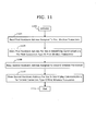
- FIG. 11 is a flowchart for describing a method for use in facilitating communications over first and second wireless connections of a wireless transceiver.
- the method of FIG. 11 may be performed by wireless device 201 described in relation to FIGs. 1-10 above, and relates to an initialization procedure of the wireless device.
- the wireless device includes a first wireless transceiver (e.g. IEEE 802.11) and a second wireless transceiver (e.g. BLUETOOTH).
- the wireless device may operate in accordance with or be compatible with the Wi-Fi P2P wireless network protocols in the Wi-Fi Peer-To-Peer (P2P) Technical specification.
- Each wireless transceiver may be contained within a hardware transceiver module or chip (e.g. IC) in the wireless device, or alternatively both wireless transceivers may be contained within the same hardware transceiver module or chip.
- Each module or chip includes a memory for storing one or more hardware addresses assigned to the one or more wireless transceivers.
- a computer program product which may embody the technique may include a computer readable medium (e.g. memory of the communication device, computer disk, CD-ROM, etc.) having computer instructions stored therein which are executable by the one or more processors of the wireless device for performing the technique.
- a computer readable medium e.g. memory of the communication device, computer disk, CD-ROM, etc.
- the wireless device performs an initialization procedure for initialization (step 1102 of FIG. 11 ).
- This initialization procedure may be performed in response to the wireless device being powered “on” or reset, for example, or from other suitable event or condition.
- the wireless device reads, from memory of the first wireless transceiver, a first hardware address assigned to the first wireless transceiver (step 1104 of FIG. 11 ).
- the wireless device stores this first hardware address in its device memory (e.g. flash memory 244 of FIG. 2 ) for subsequent use in identifying communications to and/or from the device via the first wireless transceiver for a first type of wireless connection (step 1106 of FIG. 11 ).
- the wireless device reads, from memory of the second wireless transceiver, a second hardware address assigned to the second wireless transceiver (step 1108 of FIG. 11 ).
- the wireless device stores this second hardware address in its device memory (e.g. flash memory 244 of FIG. 2 ) for subsequent use in identifying communications to and/or from the device via the first wireless transceiver for a second type of wireless connection (step 1110 of FIG. 11 ).
- the wireless device may also store this second hardware address in its device memory (e.g. flash memory 244 of FIG. 2 ) for subsequent use in identifying communications to and/or from the device via the second wireless transceiver for a third type of wireless connection.
- the flowchart ends at an end block 1112.
- the first and second hardware addresses are universally administered hardware addresses that are assigned to the first and the second wireless transceivers, respectively. These universally administered hardware addresses may be the MAC addresses assigned to the wireless transceivers during manufacture.
- the first wireless transceiver may be configured to communicate in accordance with an IEEE 802.11 communications standard
- the second wireless transceiver may be configured to communicate in accordance with a BLUETOOTH ® communications standard.
- the wireless device may utilize the MAC address of the IEEE 802.11 transceiver for identifying communications to and/or from via the IEEE 802.11 transceiver for WLAN-STA connections, and utilize the MAC address of the BLUETOOTH transceiver for identifying communications to and/or from via the IEEE 802.11 transceiver for Wi-Fi P2P connections.
- the wireless device may also utilize the MAC address of the BLUETOOTH transceiver for identifying communications to and/or from the device via the BLUETOOTH transceiver for BLUETOOTH connections.
- the first and second wireless connections may be concurrent wireless connections.
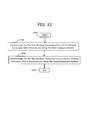
- FIG. 12 is another flowchart for describing another method for use in facilitating communications over first and second wireless connections of a wireless transceiver.
- the method of FIG. 12 may be performed by wireless device 201 described in relation to FIGs. 1-10 , with use of or without the technique of FIG. ii.
- the wireless device includes a first wireless transceiver (e.g. IEEE 802.11) and a second wireless transceiver (e.g. BLUETOOTH).
- the wireless device may operate in accordance with or be compatible with the Wi-Fi P2P wireless network protocols in the Wi-Fi Peer-To-Peer (P2P) Technical specification.
- Each wireless transceiver may be contained within a hardware transceiver module or chip (e.g. IC) in the wireless device, or alternatively both wireless transceivers may be contained within the same hardware transceiver module or chip.
- Each module or chip includes a memory for storing one or more hardware addresses assigned to the one or more wireless transceivers.
- a computer program product which may embody the technique may include a computer readable medium (e.g. memory of the communication device, computer disk, CD-ROM, etc.) having computer instructions stored therein which are executable by the one or more processors of the wireless device for performing the technique.
- a computer readable medium e.g. memory of the communication device, computer disk, CD-ROM, etc.
- the wireless device operates to communicate via the first wireless transceiver over a first wireless connection with a first device (step 1204 of FIG. 12 ).
- the communications to and from the wireless device over the first wireless connection of the first wireless transceiver are addressed with a first hardware address that is assigned to the first wireless transceiver.
- This first hardware address may be the address that was read from memory of the first wireless transceiver and stored in device memory as described in relation to steps 1104 and 1106 of FIG. 11 .
- the wireless device may receive, via the first wireless transceiver over the first wireless connection, data in one or more data frames having a destination address which is the first hardware address. Additionally or alternatively, the wireless device may send, via the first wireless transceiver over the first wireless connection, data in one or more data frames having a source address which is the first hardware address. See e.g. the discussion in relation to FIG. 9 . Also additionally or alternatively, the wireless device may operate to advertise its presence and/or availability to surrounding devices (e.g. in a discovery procedure), via the first wireless transceiver, using the first hardware address to identify itself.
- the wireless device operates to communicate via the first wireless transceiver over a second wireless connection with a second device (step 1206 of FIG. 6 ).
- the communications to and from the wireless device over the second wireless connection of the first wireless transceiver are addressed with a second hardware address that is assigned to the second wireless transceiver.
- This second hardware address may be the address that was read from memory of the second wireless transceiver and stored in device memory as described in relation to steps 1108 and 1110 of FIG. 11 .
- the wireless device may receive, via the first wireless transceiver over the second wireless connection, data in one or more data frames having a destination address which is the second hardware address. Additionally or alternatively, the wireless device may send, via the first wireless transceiver over the second wireless connection, data in one or more data frames having a source address which is the second hardware address. See again e.g. the discussion in relation to FIG. 9 . Also, for example, the wireless device may operate to advertise its presence and/or availability to surrounding devices (e.g. in a discovery procedure), via the first transceiver, using the second hardware address to identify itself.
- the first and second hardware addresses may be the universally administered hardware addresses that are assigned to the first and the second wireless transceivers, respectively. These universally administered hardware addresses may be the MAC addresses assigned to the wireless transceivers during manufacture.
- the first wireless transceiver may be configured to communicate in accordance with an IEEE 802.11 communications standard, and the second wireless transceiver may be configured to communicate in accordance with a BLUETOOTH ® communications standard.
- the first and the second wireless connections in steps 1204 and 1206 may be concurrently maintained by the wireless device.
- the wireless device may operate as a concurrent device in accordance with or be compatible with the Wi-Fi P2P wireless network protocols in the Wi-Fi Peer-To-Peer (P2P) Technical specification.
- wireless device operates to communicate via the second wireless transceiver over a third wireless connection with a third device.
- the communications to and from the wireless device over the third wireless connection of the second wireless transceiver are addressed with the second hardware address that is assigned to the second wireless transceiver.
- the wireless device may receive, via the second wireless transceiver over the second wireless connection, data in one or more data frames having a destination address which is the second hardware address.
- the wireless device may send, via the second wireless transceiver over the second wireless connection, data in one or more data frames having a source address which is the second hardware address.
- the wireless device may operate to advertise its presence and/or availability to surrounding devices (e.g. in a discovery procedure), via the second transceiver, using the second hardware address to identify itself.
- the wireless device may further operate to concurrently maintain the first, the second, and the third wireless connections via the first and the second wireless transceivers.
- the same second hardware address is utilized for identifying the communications to and/or from the wireless device over the second and the third wireless connections.
- the device operates to mark the communications for one of the wireless connections for distinguishing therebetween. For example, the device may mark the locally administered bit for the MAC address for use of the third wireless connection.
- the wireless device may operate to switch from communicating via the first wireless transceiver over the second wireless connection with the second device to communicating via the second wireless transceiver over the third wireless connection with the second device. This switching may be performed, for example, in order to reduce power consumption of the wireless device while maintaining communications with the second device. Accordingly, the wireless device may subsequently operate to switch back from communicating via the second wireless transceiver over the third wireless connection to the first wireless transceiver over the second wireless connection. This switching back may be performed for example, in order to increase data throughput of the wireless device.
- a wireless communication device of the present disclosure includes a first wireless transceiver and a second wireless transceiver.
- the wireless device is configured for communicating via the first wireless transceiver over a first wireless connection with a first device, where communications to and from the wireless device are identified using a first (universally administered) hardware address assigned to the first wireless transceiver.
- the wireless device is further configured for communicating via the first wireless transceiver over a second wireless connection with a second device, where communications to and from the wireless device are identified with a second (universally administered) hardware address assigned to the second wireless transceiver.
- the first and second hardware addresses may be Media Access Control (MAC) addresses of the first and the second wireless transceivers.
- the first and the second wireless connections may be concurrent wireless connections.
- the first wireless transceiver may be configured for communications in accordance with an IEEE 802.11 standard
- the second wireless transceiver may be configured for communications in accordance with a BLUETOOTH ® standard.
- the first wireless connection may be a wireless local area network (WLAN) infrastructure connection
- the second wireless connection may be a WiFi Peer-to-Peer (P2P) connection.
- WLAN wireless local area network
- P2P WiFi Peer-to-Peer
- the wireless device may utilize the MAC address of the IEEE 802.11 transceiver for identifying communications to and/or from the device via the IEEE 802.11 transceiver for WLAN-STA connections, and utilize the MAC address of the BLUETOOTH transceiver for identifying communications to and/or from the device via the IEEE 802.11 transceiver for Wi-Fi P2P connections.
- the first and the second types of wireless connections may be types of concurrent wireless connections.
- the first wireless transceiver may be configured for communications in accordance with an IEEE 802.11 standard
- the second wireless transceiver may be configured for communications in accordance with a BLUETOOTH standard.
- the first type of wireless connection may be a wireless local area network (WLAN) infrastructure type of connection
- the second wireless connection may be a WiFi Peer-to-Peer (P2P) type of connection.
- WLAN wireless local area network
- P2P WiFi Peer-to-Peer
- the wireless device may utilize the MAC address of the IEEE 802.11 transceiver for identifying communications to and/or from the device via the IEEE 802.11 transceiver for WLAN-STA type of connections, and utilize the MAC address of the BLUETOOTH transceiver for identifying communications to and/or from the device via the IEEE 802.11 transceiver for Wi-Fi P2P type of connections.
- the above-described embodiments of the present disclosure are intended to be examples only. Those of skill in the art may affect alterations, modifications and variations to the particular embodiments without departing from the scope of the application.
- the description relates to specific examples for illustration, where the WLAN is an IEEE 802.11-based network, for example, different environments may be applicable as well.
- the wireless networking may be based on a WiMAX network (i.e. IEEE 802.16), or an Ultra-WideBand (UWB) network (i.e. IEEE 802.15).
- WiMAX i.e. IEEE 802.16
- UWB Ultra-WideBand
Landscapes
- Engineering & Computer Science (AREA)
- Databases & Information Systems (AREA)
- Computer Networks & Wireless Communication (AREA)
- Signal Processing (AREA)
- Telephone Function (AREA)
Priority Applications (3)
| Application Number | Priority Date | Filing Date | Title |
|---|---|---|---|
| EP16196719.5A EP3174323B1 (de) | 2012-04-18 | 2012-04-18 | Verfahren und vorrichtung zur verwendung bei der bereitstellung von kommunikationen über erste und zweite drahtlosverbindungen eines drahtlosen sendeempfängers |
| EP12164555.0A EP2654331B1 (de) | 2012-04-18 | 2012-04-18 | Verfahren und Vorrichtung zur Verwendung bei der Kommunikationsunterstützung über erste und zweite drahtlose Verbindungen eines drahtlosen Sende-Empfangsgerätes |
| CA2805145A CA2805145C (en) | 2012-04-18 | 2013-02-06 | Methods and apparatus for use in facilitating communications over first and second wireless connections of a wireless transceiver |
Applications Claiming Priority (1)
| Application Number | Priority Date | Filing Date | Title |
|---|---|---|---|
| EP12164555.0A EP2654331B1 (de) | 2012-04-18 | 2012-04-18 | Verfahren und Vorrichtung zur Verwendung bei der Kommunikationsunterstützung über erste und zweite drahtlose Verbindungen eines drahtlosen Sende-Empfangsgerätes |
Related Child Applications (2)
| Application Number | Title | Priority Date | Filing Date |
|---|---|---|---|
| EP16196719.5A Division EP3174323B1 (de) | 2012-04-18 | 2012-04-18 | Verfahren und vorrichtung zur verwendung bei der bereitstellung von kommunikationen über erste und zweite drahtlosverbindungen eines drahtlosen sendeempfängers |
| EP16196719.5A Division-Into EP3174323B1 (de) | 2012-04-18 | 2012-04-18 | Verfahren und vorrichtung zur verwendung bei der bereitstellung von kommunikationen über erste und zweite drahtlosverbindungen eines drahtlosen sendeempfängers |
Publications (2)
| Publication Number | Publication Date |
|---|---|
| EP2654331A1 true EP2654331A1 (de) | 2013-10-23 |
| EP2654331B1 EP2654331B1 (de) | 2016-12-14 |
Family
ID=46044402
Family Applications (2)
| Application Number | Title | Priority Date | Filing Date |
|---|---|---|---|
| EP12164555.0A Active EP2654331B1 (de) | 2012-04-18 | 2012-04-18 | Verfahren und Vorrichtung zur Verwendung bei der Kommunikationsunterstützung über erste und zweite drahtlose Verbindungen eines drahtlosen Sende-Empfangsgerätes |
| EP16196719.5A Active EP3174323B1 (de) | 2012-04-18 | 2012-04-18 | Verfahren und vorrichtung zur verwendung bei der bereitstellung von kommunikationen über erste und zweite drahtlosverbindungen eines drahtlosen sendeempfängers |
Family Applications After (1)
| Application Number | Title | Priority Date | Filing Date |
|---|---|---|---|
| EP16196719.5A Active EP3174323B1 (de) | 2012-04-18 | 2012-04-18 | Verfahren und vorrichtung zur verwendung bei der bereitstellung von kommunikationen über erste und zweite drahtlosverbindungen eines drahtlosen sendeempfängers |
Country Status (2)
| Country | Link |
|---|---|
| EP (2) | EP2654331B1 (de) |
| CA (1) | CA2805145C (de) |
Cited By (2)
| Publication number | Priority date | Publication date | Assignee | Title |
|---|---|---|---|---|
| CN107908386A (zh) * | 2017-12-21 | 2018-04-13 | 联想(北京)有限公司 | 信息处理方法及电子设备 |
| EP3979571A4 (de) * | 2019-07-26 | 2022-12-07 | Huawei Technologies Co., Ltd. | Verfahren zur steuerung einer vorrichtung und endgerät |
Families Citing this family (3)
| Publication number | Priority date | Publication date | Assignee | Title |
|---|---|---|---|---|
| US10034179B2 (en) | 2013-10-30 | 2018-07-24 | Sai C. Manapragada | System and method for extending range and coverage of bandwidth intensive wireless data streams |
| US20220124856A1 (en) * | 2020-10-21 | 2022-04-21 | Qualcomm Incorporated | Direct link communications in multi-link operations |
| CN112911728B (zh) * | 2021-01-29 | 2023-05-02 | 极米科技股份有限公司 | 隧道直接链路建立中搜索对等终端的方法、终端及介质 |
Citations (4)
| Publication number | Priority date | Publication date | Assignee | Title |
|---|---|---|---|---|
| WO2007110473A1 (en) * | 2006-03-24 | 2007-10-04 | Teliasonera Ab | Improved solution for connectivity |
| US20080013539A1 (en) * | 2006-06-23 | 2008-01-17 | Nokia Corporation | Dynamic radio interface grouping |
| US20110134894A1 (en) * | 2009-12-03 | 2011-06-09 | Stacey Robert J | Inverse multiplexing over 802.11 wireless interfaces |
| JP2012009964A (ja) * | 2010-06-23 | 2012-01-12 | Lenovo Singapore Pte Ltd | 仮想化された無線ネットワーク・カードを有する無線端末装置 |
Family Cites Families (2)
| Publication number | Priority date | Publication date | Assignee | Title |
|---|---|---|---|---|
| EP2434834B1 (de) * | 2007-07-30 | 2016-09-07 | Marvell World Trade Ltd. | Gleichzeitige Aufrechterhaltung von Bluetooth- und 802.11-Verbindungen zur Verbesserung des Datendurchsatzes |
| US20120158839A1 (en) * | 2010-12-16 | 2012-06-21 | Microsoft Corporation | Wireless network interface with infrastructure and direct modes |
-
2012
- 2012-04-18 EP EP12164555.0A patent/EP2654331B1/de active Active
- 2012-04-18 EP EP16196719.5A patent/EP3174323B1/de active Active
-
2013
- 2013-02-06 CA CA2805145A patent/CA2805145C/en active Active
Patent Citations (4)
| Publication number | Priority date | Publication date | Assignee | Title |
|---|---|---|---|---|
| WO2007110473A1 (en) * | 2006-03-24 | 2007-10-04 | Teliasonera Ab | Improved solution for connectivity |
| US20080013539A1 (en) * | 2006-06-23 | 2008-01-17 | Nokia Corporation | Dynamic radio interface grouping |
| US20110134894A1 (en) * | 2009-12-03 | 2011-06-09 | Stacey Robert J | Inverse multiplexing over 802.11 wireless interfaces |
| JP2012009964A (ja) * | 2010-06-23 | 2012-01-12 | Lenovo Singapore Pte Ltd | 仮想化された無線ネットワーク・カードを有する無線端末装置 |
Non-Patent Citations (1)
| Title |
|---|
| SETHOM K ET AL: "Distributed virtual network interfaces to support intra-PAN and PAN-to-infrastructure connectivity", GLOBAL TELECOMMUNICATIONS CONFERENCE, 2005. GLOBECOM '05. IEEE ST. LOIUS, MO, USA 28 NOV.-2 DEC. 2005, PISCATAWAY, NJ, USA,IEEE, vol. 6, 28 November 2005 (2005-11-28), pages 3554 - 3558, XP010882301, ISBN: 978-0-7803-9414-8, DOI: 10.1109/GLOCOM.2005.1578434 * |
Cited By (3)
| Publication number | Priority date | Publication date | Assignee | Title |
|---|---|---|---|---|
| CN107908386A (zh) * | 2017-12-21 | 2018-04-13 | 联想(北京)有限公司 | 信息处理方法及电子设备 |
| EP3979571A4 (de) * | 2019-07-26 | 2022-12-07 | Huawei Technologies Co., Ltd. | Verfahren zur steuerung einer vorrichtung und endgerät |
| US12167481B2 (en) | 2019-07-26 | 2024-12-10 | Huawei Technologies Co., Ltd. | Device control method and terminal |
Also Published As
| Publication number | Publication date |
|---|---|
| EP3174323B1 (de) | 2018-11-14 |
| CA2805145C (en) | 2015-11-17 |
| EP2654331B1 (de) | 2016-12-14 |
| EP3174323A1 (de) | 2017-05-31 |
| CA2805145A1 (en) | 2013-10-18 |
Similar Documents
| Publication | Publication Date | Title |
|---|---|---|
| US8718558B2 (en) | Methods and apparatus for use in facilitating communications over first and second wireless connections of a wireless transceiver | |
| US9060329B2 (en) | Methods and apparatus for use in facilitating communication for different types of wireless networks | |
| US8953490B2 (en) | Methods and apparatus for use in facilitating Wi-Fi peer-to-peer (P2P) wireless networking | |
| US8982762B2 (en) | Methods and apparatus for use in communicating in a peer-to-peer (P2P) network | |
| CA2816743C (en) | Methods and apparatus for use in facilitating communication for different types of wireless networks | |
| US9167512B2 (en) | Methods and apparatus for use in controlling connections to wireless networks | |
| US8977856B2 (en) | Methods and apparatus for use in sharing credentials amongst a plurality of mobile communication devices | |
| CN111954283B (zh) | 一种接入无线局域网的方法和终端 | |
| EP2757738B1 (de) | Kommunikationssteuerungssystem, Kommunikationssystem, Kommunikationsverfahren und Trägermedium mit darauf gespeichertem Kommunikationssteuerungsprogramm | |
| CA2862872C (en) | Methods and apparatus for use in facilitating wi-fi peer-to-peer (p2p) wireless networking | |
| CA2805145C (en) | Methods and apparatus for use in facilitating communications over first and second wireless connections of a wireless transceiver | |
| US8666394B1 (en) | Methods and apparatus for use in negotiating a group owner for a P2P network having external network connectivity | |
| EP2713670B1 (de) | Verfahren und Vorrichtung zur Verwendung bei der Kommunikation in einem Peer-to-Peer-Netzwerk (P2P) | |
| EP2744247B1 (de) | Steuerung von Verbindungen mit drahtlosen Netzwerken | |
| EP2731368B1 (de) | Verfahren, Computerprogrammprodukt und Vorrichtung für die Verwendung bei der Verhandlung eines Gruppeneigentümers für ein P2P-Netzwerk mit externer Netzwerkkonnektivität | |
| US9191991B2 (en) | Methods and apparatus for reducing the impact of RF interference based on estimation of colored noise | |
| KR102822960B1 (ko) | Ap 리스트를 제공하는 전자 장치 및 전자 장치의 동작 방법 | |
| CA2825321C (en) | Methods and apparatus for use in sharing credentials amongst a plurality of mobile communication devices | |
| EP2773162B1 (de) | Verfahren und Vorrichtung zur Verringerung der Auswirkungen von HF-Interferenzen basierend auf Farbrauschschätzung | |
| EP2773152B1 (de) | Zugriffspunkt- und Kanalauswahl in einem drahtlosen Netzwerk für verringerte HF-Interferenz |
Legal Events
| Date | Code | Title | Description |
|---|---|---|---|
| PUAI | Public reference made under article 153(3) epc to a published international application that has entered the european phase |
Free format text: ORIGINAL CODE: 0009012 |
|
| 17P | Request for examination filed |
Effective date: 20120418 |
|
| AK | Designated contracting states |
Kind code of ref document: A1 Designated state(s): AL AT BE BG CH CY CZ DE DK EE ES FI FR GB GR HR HU IE IS IT LI LT LU LV MC MK MT NL NO PL PT RO RS SE SI SK SM TR |
|
| AX | Request for extension of the european patent |
Extension state: BA ME |
|
| RAP1 | Party data changed (applicant data changed or rights of an application transferred) |
Owner name: BLACKBERRY LIMITED |
|
| GRAP | Despatch of communication of intention to grant a patent |
Free format text: ORIGINAL CODE: EPIDOSNIGR1 |
|
| INTG | Intention to grant announced |
Effective date: 20160621 |
|
| GRAS | Grant fee paid |
Free format text: ORIGINAL CODE: EPIDOSNIGR3 |
|
| GRAA | (expected) grant |
Free format text: ORIGINAL CODE: 0009210 |
|
| AK | Designated contracting states |
Kind code of ref document: B1 Designated state(s): AL AT BE BG CH CY CZ DE DK EE ES FI FR GB GR HR HU IE IS IT LI LT LU LV MC MK MT NL NO PL PT RO RS SE SI SK SM TR |
|
| REG | Reference to a national code |
Ref country code: GB Ref legal event code: FG4D |
|
| REG | Reference to a national code |
Ref country code: CH Ref legal event code: EP |
|
| REG | Reference to a national code |
Ref country code: IE Ref legal event code: FG4D |
|
| REG | Reference to a national code |
Ref country code: AT Ref legal event code: REF Ref document number: 854542 Country of ref document: AT Kind code of ref document: T Effective date: 20170115 |
|
| REG | Reference to a national code |
Ref country code: DE Ref legal event code: R096 Ref document number: 602012026510 Country of ref document: DE |
|
| PG25 | Lapsed in a contracting state [announced via postgrant information from national office to epo] |
Ref country code: LV Free format text: LAPSE BECAUSE OF FAILURE TO SUBMIT A TRANSLATION OF THE DESCRIPTION OR TO PAY THE FEE WITHIN THE PRESCRIBED TIME-LIMIT Effective date: 20161214 |
|
| REG | Reference to a national code |
Ref country code: LT Ref legal event code: MG4D |
|
| REG | Reference to a national code |
Ref country code: NL Ref legal event code: MP Effective date: 20161214 |
|
| REG | Reference to a national code |
Ref country code: FR Ref legal event code: PLFP Year of fee payment: 6 |
|
| PG25 | Lapsed in a contracting state [announced via postgrant information from national office to epo] |
Ref country code: SE Free format text: LAPSE BECAUSE OF FAILURE TO SUBMIT A TRANSLATION OF THE DESCRIPTION OR TO PAY THE FEE WITHIN THE PRESCRIBED TIME-LIMIT Effective date: 20161214 Ref country code: LT Free format text: LAPSE BECAUSE OF FAILURE TO SUBMIT A TRANSLATION OF THE DESCRIPTION OR TO PAY THE FEE WITHIN THE PRESCRIBED TIME-LIMIT Effective date: 20161214 Ref country code: GR Free format text: LAPSE BECAUSE OF FAILURE TO SUBMIT A TRANSLATION OF THE DESCRIPTION OR TO PAY THE FEE WITHIN THE PRESCRIBED TIME-LIMIT Effective date: 20170315 Ref country code: NO Free format text: LAPSE BECAUSE OF FAILURE TO SUBMIT A TRANSLATION OF THE DESCRIPTION OR TO PAY THE FEE WITHIN THE PRESCRIBED TIME-LIMIT Effective date: 20170314 |
|
| REG | Reference to a national code |
Ref country code: AT Ref legal event code: MK05 Ref document number: 854542 Country of ref document: AT Kind code of ref document: T Effective date: 20161214 |
|
| PG25 | Lapsed in a contracting state [announced via postgrant information from national office to epo] |
Ref country code: FI Free format text: LAPSE BECAUSE OF FAILURE TO SUBMIT A TRANSLATION OF THE DESCRIPTION OR TO PAY THE FEE WITHIN THE PRESCRIBED TIME-LIMIT Effective date: 20161214 Ref country code: HR Free format text: LAPSE BECAUSE OF FAILURE TO SUBMIT A TRANSLATION OF THE DESCRIPTION OR TO PAY THE FEE WITHIN THE PRESCRIBED TIME-LIMIT Effective date: 20161214 Ref country code: RS Free format text: LAPSE BECAUSE OF FAILURE TO SUBMIT A TRANSLATION OF THE DESCRIPTION OR TO PAY THE FEE WITHIN THE PRESCRIBED TIME-LIMIT Effective date: 20161214 |
|
| PG25 | Lapsed in a contracting state [announced via postgrant information from national office to epo] |
Ref country code: NL Free format text: LAPSE BECAUSE OF FAILURE TO SUBMIT A TRANSLATION OF THE DESCRIPTION OR TO PAY THE FEE WITHIN THE PRESCRIBED TIME-LIMIT Effective date: 20161214 |
|
| PG25 | Lapsed in a contracting state [announced via postgrant information from national office to epo] |
Ref country code: CZ Free format text: LAPSE BECAUSE OF FAILURE TO SUBMIT A TRANSLATION OF THE DESCRIPTION OR TO PAY THE FEE WITHIN THE PRESCRIBED TIME-LIMIT Effective date: 20161214 Ref country code: EE Free format text: LAPSE BECAUSE OF FAILURE TO SUBMIT A TRANSLATION OF THE DESCRIPTION OR TO PAY THE FEE WITHIN THE PRESCRIBED TIME-LIMIT Effective date: 20161214 Ref country code: IS Free format text: LAPSE BECAUSE OF FAILURE TO SUBMIT A TRANSLATION OF THE DESCRIPTION OR TO PAY THE FEE WITHIN THE PRESCRIBED TIME-LIMIT Effective date: 20170414 Ref country code: SK Free format text: LAPSE BECAUSE OF FAILURE TO SUBMIT A TRANSLATION OF THE DESCRIPTION OR TO PAY THE FEE WITHIN THE PRESCRIBED TIME-LIMIT Effective date: 20161214 Ref country code: RO Free format text: LAPSE BECAUSE OF FAILURE TO SUBMIT A TRANSLATION OF THE DESCRIPTION OR TO PAY THE FEE WITHIN THE PRESCRIBED TIME-LIMIT Effective date: 20161214 |
|
| PG25 | Lapsed in a contracting state [announced via postgrant information from national office to epo] |
Ref country code: PL Free format text: LAPSE BECAUSE OF FAILURE TO SUBMIT A TRANSLATION OF THE DESCRIPTION OR TO PAY THE FEE WITHIN THE PRESCRIBED TIME-LIMIT Effective date: 20161214 Ref country code: BE Free format text: LAPSE BECAUSE OF FAILURE TO SUBMIT A TRANSLATION OF THE DESCRIPTION OR TO PAY THE FEE WITHIN THE PRESCRIBED TIME-LIMIT Effective date: 20161214 Ref country code: BG Free format text: LAPSE BECAUSE OF FAILURE TO SUBMIT A TRANSLATION OF THE DESCRIPTION OR TO PAY THE FEE WITHIN THE PRESCRIBED TIME-LIMIT Effective date: 20170314 Ref country code: AT Free format text: LAPSE BECAUSE OF FAILURE TO SUBMIT A TRANSLATION OF THE DESCRIPTION OR TO PAY THE FEE WITHIN THE PRESCRIBED TIME-LIMIT Effective date: 20161214 Ref country code: ES Free format text: LAPSE BECAUSE OF FAILURE TO SUBMIT A TRANSLATION OF THE DESCRIPTION OR TO PAY THE FEE WITHIN THE PRESCRIBED TIME-LIMIT Effective date: 20161214 Ref country code: IT Free format text: LAPSE BECAUSE OF FAILURE TO SUBMIT A TRANSLATION OF THE DESCRIPTION OR TO PAY THE FEE WITHIN THE PRESCRIBED TIME-LIMIT Effective date: 20161214 Ref country code: SM Free format text: LAPSE BECAUSE OF FAILURE TO SUBMIT A TRANSLATION OF THE DESCRIPTION OR TO PAY THE FEE WITHIN THE PRESCRIBED TIME-LIMIT Effective date: 20161214 Ref country code: PT Free format text: LAPSE BECAUSE OF FAILURE TO SUBMIT A TRANSLATION OF THE DESCRIPTION OR TO PAY THE FEE WITHIN THE PRESCRIBED TIME-LIMIT Effective date: 20170414 |
|
| REG | Reference to a national code |
Ref country code: DE Ref legal event code: R097 Ref document number: 602012026510 Country of ref document: DE |
|
| PLBE | No opposition filed within time limit |
Free format text: ORIGINAL CODE: 0009261 |
|
| STAA | Information on the status of an ep patent application or granted ep patent |
Free format text: STATUS: NO OPPOSITION FILED WITHIN TIME LIMIT |
|
| 26N | No opposition filed |
Effective date: 20170915 |
|
| PG25 | Lapsed in a contracting state [announced via postgrant information from national office to epo] |
Ref country code: DK Free format text: LAPSE BECAUSE OF FAILURE TO SUBMIT A TRANSLATION OF THE DESCRIPTION OR TO PAY THE FEE WITHIN THE PRESCRIBED TIME-LIMIT Effective date: 20161214 |
|
| REG | Reference to a national code |
Ref country code: CH Ref legal event code: PL |
|
| REG | Reference to a national code |
Ref country code: IE Ref legal event code: MM4A |
|
| PG25 | Lapsed in a contracting state [announced via postgrant information from national office to epo] |
Ref country code: MC Free format text: LAPSE BECAUSE OF FAILURE TO SUBMIT A TRANSLATION OF THE DESCRIPTION OR TO PAY THE FEE WITHIN THE PRESCRIBED TIME-LIMIT Effective date: 20161214 |
|
| PG25 | Lapsed in a contracting state [announced via postgrant information from national office to epo] |
Ref country code: LU Free format text: LAPSE BECAUSE OF NON-PAYMENT OF DUE FEES Effective date: 20170418 Ref country code: LI Free format text: LAPSE BECAUSE OF NON-PAYMENT OF DUE FEES Effective date: 20170430 Ref country code: SI Free format text: LAPSE BECAUSE OF FAILURE TO SUBMIT A TRANSLATION OF THE DESCRIPTION OR TO PAY THE FEE WITHIN THE PRESCRIBED TIME-LIMIT Effective date: 20161214 Ref country code: CH Free format text: LAPSE BECAUSE OF NON-PAYMENT OF DUE FEES Effective date: 20170430 |
|
| REG | Reference to a national code |
Ref country code: FR Ref legal event code: PLFP Year of fee payment: 7 |
|
| PG25 | Lapsed in a contracting state [announced via postgrant information from national office to epo] |
Ref country code: IE Free format text: LAPSE BECAUSE OF NON-PAYMENT OF DUE FEES Effective date: 20170418 |
|
| PG25 | Lapsed in a contracting state [announced via postgrant information from national office to epo] |
Ref country code: MT Free format text: LAPSE BECAUSE OF NON-PAYMENT OF DUE FEES Effective date: 20170418 |
|
| PG25 | Lapsed in a contracting state [announced via postgrant information from national office to epo] |
Ref country code: HU Free format text: LAPSE BECAUSE OF FAILURE TO SUBMIT A TRANSLATION OF THE DESCRIPTION OR TO PAY THE FEE WITHIN THE PRESCRIBED TIME-LIMIT; INVALID AB INITIO Effective date: 20120418 |
|
| PG25 | Lapsed in a contracting state [announced via postgrant information from national office to epo] |
Ref country code: CY Free format text: LAPSE BECAUSE OF NON-PAYMENT OF DUE FEES Effective date: 20161214 |
|
| PG25 | Lapsed in a contracting state [announced via postgrant information from national office to epo] |
Ref country code: MK Free format text: LAPSE BECAUSE OF FAILURE TO SUBMIT A TRANSLATION OF THE DESCRIPTION OR TO PAY THE FEE WITHIN THE PRESCRIBED TIME-LIMIT Effective date: 20161214 |
|
| PG25 | Lapsed in a contracting state [announced via postgrant information from national office to epo] |
Ref country code: TR Free format text: LAPSE BECAUSE OF FAILURE TO SUBMIT A TRANSLATION OF THE DESCRIPTION OR TO PAY THE FEE WITHIN THE PRESCRIBED TIME-LIMIT Effective date: 20161214 |
|
| PG25 | Lapsed in a contracting state [announced via postgrant information from national office to epo] |
Ref country code: AL Free format text: LAPSE BECAUSE OF FAILURE TO SUBMIT A TRANSLATION OF THE DESCRIPTION OR TO PAY THE FEE WITHIN THE PRESCRIBED TIME-LIMIT Effective date: 20161214 |
|
| REG | Reference to a national code |
Ref country code: DE Ref legal event code: R082 Ref document number: 602012026510 Country of ref document: DE Ref country code: DE Ref legal event code: R081 Ref document number: 602012026510 Country of ref document: DE Owner name: MALIKIE INNOVATIONS LTD., IE Free format text: FORMER OWNER: BLACKBERRY LIMITED, WATERLOO, ONTARIO, CA |
|
| REG | Reference to a national code |
Ref country code: GB Ref legal event code: 732E Free format text: REGISTERED BETWEEN 20240530 AND 20240605 |
|
| PGFP | Annual fee paid to national office [announced via postgrant information from national office to epo] |
Ref country code: DE Payment date: 20250428 Year of fee payment: 14 |
|
| PGFP | Annual fee paid to national office [announced via postgrant information from national office to epo] |
Ref country code: FR Payment date: 20250424 Year of fee payment: 14 |
|
| PGFP | Annual fee paid to national office [announced via postgrant information from national office to epo] |
Ref country code: GB Payment date: 20260319 Year of fee payment: 15 |