EP2654548B1 - Verfahren und einrichtung zur untersuchung eines hohlorgans mit einer magnetgeführten endoskopkapsel - Google Patents
Verfahren und einrichtung zur untersuchung eines hohlorgans mit einer magnetgeführten endoskopkapsel Download PDFInfo
- Publication number
- EP2654548B1 EP2654548B1 EP12703077.3A EP12703077A EP2654548B1 EP 2654548 B1 EP2654548 B1 EP 2654548B1 EP 12703077 A EP12703077 A EP 12703077A EP 2654548 B1 EP2654548 B1 EP 2654548B1
- Authority
- EP
- European Patent Office
- Prior art keywords
- image
- groups
- relevant
- value
- hollow organ
- Prior art date
- Legal status (The legal status is an assumption and is not a legal conclusion. Google has not performed a legal analysis and makes no representation as to the accuracy of the status listed.)
- Not-in-force
Links
Images

Classifications
-
- A—HUMAN NECESSITIES
- A61—MEDICAL OR VETERINARY SCIENCE; HYGIENE
- A61B—DIAGNOSIS; SURGERY; IDENTIFICATION
- A61B1/00—Instruments for performing medical examinations of the interior of cavities or tubes of the body by visual or photographical inspection, e.g. endoscopes; Illuminating arrangements therefor
- A61B1/04—Instruments for performing medical examinations of the interior of cavities or tubes of the body by visual or photographical inspection, e.g. endoscopes; Illuminating arrangements therefor combined with photographic or television appliances
- A61B1/041—Capsule endoscopes for imaging
-
- A—HUMAN NECESSITIES
- A61—MEDICAL OR VETERINARY SCIENCE; HYGIENE
- A61B—DIAGNOSIS; SURGERY; IDENTIFICATION
- A61B1/00—Instruments for performing medical examinations of the interior of cavities or tubes of the body by visual or photographical inspection, e.g. endoscopes; Illuminating arrangements therefor
- A61B1/00002—Operational features of endoscopes
- A61B1/00004—Operational features of endoscopes characterised by electronic signal processing
- A61B1/00009—Operational features of endoscopes characterised by electronic signal processing of image signals during a use of endoscope
- A61B1/000094—Operational features of endoscopes characterised by electronic signal processing of image signals during a use of endoscope extracting biological structures
-
- A—HUMAN NECESSITIES
- A61—MEDICAL OR VETERINARY SCIENCE; HYGIENE
- A61B—DIAGNOSIS; SURGERY; IDENTIFICATION
- A61B1/00—Instruments for performing medical examinations of the interior of cavities or tubes of the body by visual or photographical inspection, e.g. endoscopes; Illuminating arrangements therefor
- A61B1/00147—Holding or positioning arrangements
- A61B1/00158—Holding or positioning arrangements using magnetic field
-
- A—HUMAN NECESSITIES
- A61—MEDICAL OR VETERINARY SCIENCE; HYGIENE
- A61B—DIAGNOSIS; SURGERY; IDENTIFICATION
- A61B1/00—Instruments for performing medical examinations of the interior of cavities or tubes of the body by visual or photographical inspection, e.g. endoscopes; Illuminating arrangements therefor
- A61B1/04—Instruments for performing medical examinations of the interior of cavities or tubes of the body by visual or photographical inspection, e.g. endoscopes; Illuminating arrangements therefor combined with photographic or television appliances
- A61B1/043—Instruments for performing medical examinations of the interior of cavities or tubes of the body by visual or photographical inspection, e.g. endoscopes; Illuminating arrangements therefor combined with photographic or television appliances for fluorescence imaging
-
- G—PHYSICS
- G06—COMPUTING OR CALCULATING; COUNTING
- G06T—IMAGE DATA PROCESSING OR GENERATION, IN GENERAL
- G06T7/00—Image analysis
- G06T7/10—Segmentation; Edge detection
- G06T7/11—Region-based segmentation
-
- G—PHYSICS
- G06—COMPUTING OR CALCULATING; COUNTING
- G06T—IMAGE DATA PROCESSING OR GENERATION, IN GENERAL
- G06T7/00—Image analysis
- G06T7/10—Segmentation; Edge detection
- G06T7/136—Segmentation; Edge detection involving thresholding
-
- G—PHYSICS
- G06—COMPUTING OR CALCULATING; COUNTING
- G06T—IMAGE DATA PROCESSING OR GENERATION, IN GENERAL
- G06T2207/00—Indexing scheme for image analysis or image enhancement
- G06T2207/10—Image acquisition modality
- G06T2207/10068—Endoscopic image
-
- G—PHYSICS
- G06—COMPUTING OR CALCULATING; COUNTING
- G06T—IMAGE DATA PROCESSING OR GENERATION, IN GENERAL
- G06T2207/00—Indexing scheme for image analysis or image enhancement
- G06T2207/30—Subject of image; Context of image processing
- G06T2207/30004—Biomedical image processing
- G06T2207/30028—Colon; Small intestine
-
- G—PHYSICS
- G06—COMPUTING OR CALCULATING; COUNTING
- G06T—IMAGE DATA PROCESSING OR GENERATION, IN GENERAL
- G06T2207/00—Indexing scheme for image analysis or image enhancement
- G06T2207/30—Subject of image; Context of image processing
- G06T2207/30004—Biomedical image processing
- G06T2207/30092—Stomach; Gastric
Definitions
- the invention relates to a device for examining a hollow organ with a magnet-guided endoscope capsule.
- the DE 101 42 253 C1 known to introduce into the hollow organ an endoscope capsule in the study of the gastrointestinal tract, for example, by swallowing, which can be freely maneuvered without solid compound to the outside in the hollow organ by external magnetic fields.
- the physician carrying out the diagnosis must process a large number of images consecutive at short intervals on the one hand with regard to possibly existing diagnostically relevant image contents, on the other hand also with regard to a correct control of the endoscope capsule.
- the control of the endoscope capsule requires a high degree of attention, so that in principle there is a risk that the examining doctor overlooks diagnostically relevant details.
- the invention is therefore based on the object of specifying a device for examining a hollow organ with a magnet-guided endoscope capsule, with which the likelihood with which pathological structures in the hollow organ can be detected increases and accordingly reduces the probability of false-negative or false-positive diagnosis is.
- the indicative on a clinical picture ie diagnostically relevant information can be derived, for example, directly from a recognizable in the video image pathological change on the wall of the hollow organ or indirectly from the Opacityseigenschaften the fluid contained in the hollow organ, as certain diseases also by locally varying turbidity or color of the Liquid or by the presence of particles in the liquid.
- the device is particularly suitable for detecting acute gastritis (gastritis). Recognition of such gastritis is of particular interest as it is one of the major causes of gastric cancer.
- the invention is based on the consideration that the recognition of diagnostically relevant areas of the wall or diagnostically relevant properties of the liquid in which the endoscope capsule floats can be used during the examination to open the endoscope capsule, ie. H. to control their movement and orientation within the hollow organ in order to subject the possibly identically identified wall area of the hollow organ or the irregularities discovered in the fluid itself to more extensive endoscopic examination, for example by stopping the endoscope capsule and moving it closer to the relevant surface area to give the doctor a closer look.
- This may be, for example, a higher magnification or a viewing from different angles, which allows it to better judge whether it is indeed a gastric region or not.
- the endoscope capsule can be rotated to further analyze the properties of the fluid in different directions, for example to locate the cause of the change, for example the location on the wall where particulate separation takes place so that it can be examined more closely.
- This control can either be automated or performed manually by the doctor if visually or visually such an indication of the possible presence of a pathological change is displayed when viewing the video images on the monitor.
- a method with the above-mentioned method steps a) to f) is particularly suitable for generating the evaluated test images required for the automated analysis by manually classifying the relevant groups generated from a video image with these method steps as diagnostically relevant or diagnostically irrelevant, i. H. be considered and evaluated by a human expert.
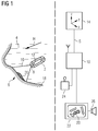
- FIG. 1 There is a magnet-guided endoscope capsule 2 in a filled with a liquid 4 hollow organ 6, for example, a stomach.
- a liquid 4 hollow organ 6 for example, a stomach.
- video images are continuously recorded and transmitted by radio to an external control and evaluation device 10.
- a permanent magnet 12 is arranged in the endoscope capsule 2.
- the guidance, ie the movement and alignment of the endoscope capsule 2 takes place with the aid of an inhomogeneous magnetic field H, which is generated by an external magnet system 14 which comprises, for example, three magnet coils whose coil axes are oriented perpendicular to one another and define a device reference system xyz.
- a pathological structure 20 for example, a local inflammation (gastric area).
- the video images recorded by the video camera 8 and transmitted to the control and evaluation device 10 are reproduced on a monitor 22.
- the pathological structure 20 can be recognized on the monitor 22 and highlighted by hatching.
- the magnet system 14 is controlled by means of control signals S, which are generated by the control and evaluation device 10 either automatically or by inputs from a user via an external input unit 24, illustrated in the example by a joystick.
- control and evaluation unit 10 image processing algorithms are implemented, with which it is possible to automatically detect pathological structures 20 and mark them in the video image, as indicated by the hatching.
- other visual or acoustic displays can be found in the Fig. 1 symbolized by a loudspeaker 26, which point the operator to the presence of one of the control and evaluation unit 10 as a pathologically classified structure 20 to provide them with the opportunity to examine this possibly pathological structure 20 closer by, for example, the Endoscope capsule 2 stops or closer to the structure 20 drove to more certainly assess whether it is actually a pathological phenomenon or not.
- FIGS. 2a and b illustrated by a flow chart.
- the basis for this is the consideration that in the transition region between a pathological structure, for example a gastritic region, and the adjoining non-pathological structure, for example a non-gastritic region, there are pronounced intensity changes which are also found in the single-channel gray value image G.
- this gray-scale image G high intensity gradients can then be localized with 2D filters, for example after previous smoothing with an edge filter.
- the gray-scale image G is accordingly convoluted in step 34 with a filter kernel K which is preferably itself a convolution of a Gaussian filter and a Laplace filter (a so-called L (aplacian) o (f) G (Gaussian) filter) to form regions pronounced edges, where the intensity changes with high spatial frequency.
- the number of columns or rows of the filter core used here corresponds approximately to the number of pixels (pixels) which are located in a transition zone forming the edge between an inflamed area and a healthy area.
- a first threshold value t F is now searched in step 36, with the aid of which relevant amplitude changes of non-relevant amplitude changes can be separated. Since the video images produced differ considerably in terms of their contrast and the lighting conditions, a fixed threshold value is unsuitable for this purpose.
- a histogram with, for example, 256 equal intervals formed whose lower limit is formed by the minimal filter value and the upper limit by the maximum filter value. This is in the Histogram analyzes in which interval one quarter of the maximum filter value is exceeded. The lower limit of this interval determines the first threshold.
- groups bin i (x, y) are formed from 15x15 pixels each.
- the original image data v (x, y) of the video image O of these relevant groups bin i, rel (x, y), ie the original RGB values of the individual remaining relevant pixels x, y are used.
- the original image data v of each relevant group bin i, rel (x, y) are now analyzed in step 46 for a variety of properties. These are in the present case color properties, properties of the color histogram, color structure properties, texture properties and filter properties. An example of color properties is the mean and the maximum value for each channel of the RGB color space within such a group is i i, rel (x, y).
- color histograms for the R channel in the RGB color space, the third channel in the HSV color space and the L channel of the Lab color space are formed.
- the color structure properties serve to distinguish between the quantitative and spatial distribution of color properties within a group bin i, rel (x, y).
- the groups bin i, rel (x, y) are subdivided into subgroups.
- 25 subgroups each of 3 x 3 pixels are formed in each of the groups bin i, rel (x, y).
- Now in five color channels RGB color space: R, G, B, Lab color space: L, HSV color space: V) the occurrence of a special color property is detected.
- the frequency of occurrence of a particular color characteristic in one of these channels within the subgroup is then recorded.
- the gray values g of the unfiltered gray value image G present in this group are also used, and a so-called differenceof-box filter is applied whose filter response has high negative and positive amplitudes for spatial changes of intensity.
- each relevant group bin i, rel (x, y) is assigned a property vector e with a number of components corresponding to the number m of properties.
- the original image data of the relevant groups bin i, rel (x, y) extracted in each of the test images according to the method explained above are evaluated by an expert for their diagnostic relevance.
- two classes C1, C2 are formed.
- Relevant groups bin i, rel (x, y) with positive finding (diagnostically relevant) are assigned to class C1, the remaining (diagnostically irrelevant) to class C2 (step 48).
- the system is trained in such a way on the basis of the characteristic vector bin i, rel (x, y) associated with each relevant group bin i, rel (x, y) high probability can decide which class C1, C2 this group i, rel (x, y) can be assigned.
- the properties used for the later automated image analysis ie the actually necessary and suitable, ie relevant components of the property vector, are also extracted from a larger number of properties by disregarding those components that are used in the training phase for both Groups are i, rel (x, y) of class C1 as well as the groups bin i, rel (x, y) of class C2 the value 0. Equally, those features whose variance in group C1 is greater than or nearly equal to the variance of that feature in the total number of groups are still considered.
- the expert system With the expert system trained in this way, it is now judged in steps 46 and 48 which class C1, C2 the relevant groups bin i, rel (x, y) identified in a video image generated during an endoscopic examination with steps 30 to 42 are to be assigned , In other words, the expert system automatically judges whether or not the relevant group bin i rel indicates a gastric region. If relevant groups bin i, rel of a video image of class C1 have been assigned, this is indicated acoustically or optically, for example within the video image, by a corresponding highlighting to the user, so that he can actively intervene in the control of the endoscope capsule. In addition or as an alternative to such a manual control, automatic control of the endoscope capsule may also be provided.
- the above-described method is particularly suitable for the detection of gastritis and can in principle be used with the same preprocessing, for selecting the relevant groups bin i, rel (x, y) leading steps for the automatic detection of other clinical pictures in which the diagnostically relevant information in a locally variable turbidity and / or coloration of a liquid located in the hollow organ and / or a presence of particles in the liquid, ie in which the optical properties of the liquid indicate the presence of a clinical picture.
- these foreign bodies may be tissue parts which flake like in a gastric ulcer of detach the stomach wall. These tissue flakes are then recognized in the endoscope image as floating in the liquid particles.
- the type, amount and size of these foreign bodies provide a very good first indication of whether a particular disease is present, even if the affected anatomical site has not yet been sighted with the endoscope.
- To recognize the foreign body in the endoscope usually as a floating particles, but may also be formed in small size as clouding of the liquid.
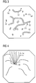
- FIG. 3 is schematically reproduced an endoscopic image in which exudate has detached from the stomach wall as a result of a gastric ulcer and floats as whitish fluffy foreign body 50 in the liquid.
- these flakes 50 are clearly recognizable as bright white image areas compared to the structures located in the background on the stomach wall, as well as the stomach wall, and thus can be automatically segmented and analyzed in terms of size and number.
- FIG. 4 Another disease is shown in which bile enters the stomach as a yellowish-green to brownish fluid through the pylorus (stomach exit) 56, if it can not prevent reflux. It mixes with the fluid in which the endoscope capsule floats and obscures it, especially in the vicinity of the pylorus. This local turbidity can also be detected automatically, thus allowing conclusions to be drawn about the functional efficiency of the pylorus. In addition, a liver malfunction can also be detected from the automatically determined color composition of the fluid.
- Bile occurring in the fluid consists of various chemical components, some of which are clear and others which are colored, so that the color of the bile varies from yellowish to greenish depending on the proportion of the main bile in the bile, namely yellow bilirubin and green biliverdin. Both are breakdown products of the liver of hemoglobin.
- the bile fluid thus appears more yellowish or greenish and allows conclusions about liver dysfunctions for certain color shifts.
- This color difference is maintained when mixed with the liquid solution in the working space (stomach and / or intestine) and can be detected automatically by means of an analysis of the endoscope images with methods of digital image processing or analysis.
Landscapes
- Health & Medical Sciences (AREA)
- Life Sciences & Earth Sciences (AREA)
- Surgery (AREA)
- Engineering & Computer Science (AREA)
- Physics & Mathematics (AREA)
- Medical Informatics (AREA)
- Animal Behavior & Ethology (AREA)
- Radiology & Medical Imaging (AREA)
- Optics & Photonics (AREA)
- Nuclear Medicine, Radiotherapy & Molecular Imaging (AREA)
- Biomedical Technology (AREA)
- Heart & Thoracic Surgery (AREA)
- Biophysics (AREA)
- Molecular Biology (AREA)
- Pathology (AREA)
- General Health & Medical Sciences (AREA)
- Public Health (AREA)
- Veterinary Medicine (AREA)
- Signal Processing (AREA)
- Computer Vision & Pattern Recognition (AREA)
- General Physics & Mathematics (AREA)
- Theoretical Computer Science (AREA)
- Endoscopes (AREA)
- Image Processing (AREA)
Description
- Einrichtung zur Untersuchung eines Hohlorgans mit einer magnetgeführten Endoskopkapsel
- Die Erfindung bezieht sich auf eine Einrichtung zur Untersuchung eines Hohlorgans mit einer magnetgeführten Endoskopkapsel.
- Zur optischen Untersuchung der Innenoberfläche eines im Körper eines Lebewesens befindlichen Hohlorgans, beispielsweise des Magen-Darmtraktes eines Patienten, ist es beispielsweise aus der
DE 101 42 253 C1 bekannt, in das Hohlorgan eine Endoskopkapsel, bei der Untersuchung des Magen-Darmtraktes beispielsweise durch Schlucken einzubringen, die ohne feste Verbindung nach außen im Hohlorgan durch externe Magnetfelder frei manövrierbar ist. - Bei einer solchen endoskopischen Untersuchung (magnetgeführte Kapselendoskopie) muss der die Diagnose durchführende Arzt eine Vielzahl von in kurzen Zeitabständen aufeinanderfolgenden Bildern einerseits hinsichtlich gegebenenfalls vorhandener diagnostisch relevanter Bildinhalte, andererseits auch im Hinblick auf eine korrekte Steuerung der Endoskopkapsel verarbeiten. Allein die Steuerung der Endoskopkapsel erfordert jedoch ein hohes Maß an Aufmerksamkeit, so dass grundsätzlich das Risiko besteht, dass der die Untersuchung durchführende Arzt diagnostisch relevante Details übersieht.
- Zwar ist es bei der passiven Kapselendoskopie grundsätzlich bekannt, das vorhandene Bildmaterial nachträglich einer digitalen Bildverarbeitung zu unterziehen, um auf diese Weise mit Methoden der computerunterstützten Diagnose (CAD) Verfahren zur Verfügung zu stellen, mit denen es möglich ist, klinisch relevante pathologische Strukturen automatisch zu erkennen und auf diese Weise dem untersuchenden Arzt die Auswertung zu erleichtern.
- Eine solche nachträgliche automatisierte Auswertung würde jedoch auch bei der magnetgeführten Kapselendoskopie auf der Grundlage des verfügbaren Videomaterials erfolgen, so dass nach wie vor das Risiko besteht, dass pathologische Erscheinungsformen nicht oder nur undeutlich auf den Videobildern wiedergegeben werden, da diese von der Endoskopkapsel nicht oder nur undeutlich erfasst worden sind, weil der untersuchende Arzt die diagnostische Relevanz während der Untersuchung nicht erkannt und bei der Steuerung der magnetgeführten Endoskopkapsel nicht entsprechend berücksichtigt hat.
- Der Erfindung liegt daher die Aufgabe zugrunde, eine Einrichtung zur Untersuchung eines Hohlorgans mit einer magnetgeführten Endoskopkapsel anzugeben, mit dem die Wahrscheinlichkeit, mit der pathologische Strukturen in Hohlorgan erkannt werden können, erhöht und dementsprechend die Wahrscheinlichkeit einer falsch-negativen oder falsch-positiven Diagnose verringert ist.
- Die genannte Aufgabe wird gemäß der Erfindung gelöst, mit einer Einrichtung mit den Merkmalen des Patentanspruches 1. Gemäß diesen Merkmalen werden die aus dem Inneren des Hohlorgans fortlaufend mit der magnetgeführten Endoskopkapsel erzeugten Videobilder während der Navigation der Endoskopkapsel im Hohlraum mit Methoden der digitalen Bildverarbeitung automatisch auf das Vorhandensein diagnostisch relevanter Information analysiert, und es wird das Ergebnis der Analyse, d.h. eine Aussage darüber, ob die Videobilder eine diagnostisch relevante, d.h. auf ein Krankheitsbild hinweisende Information enthalten oder nicht, zur Steuerung der Endoskopkapsel herangezogen. Die Analyse umfasst dabei die folgenden weiteren Schritte:
- a) aus den Videobildern wird zum Lokalisieren von hohen Intensitätsgradienten durch Vorbearbeitung jeweils ein Grauwertbild erzeugt, dessen Bildpunkten jeweils ein Grauwert zugeordnet wird,
- b) aus dem Grauwertbild wird durch Glättung und Kantenfilterung ein gefiltertes Bild erzeugt, dessen Bildpunkten ein Filterwert zugeordnet ist,
- c) aus den Filterwerten der Bildpunkte des gefilterten Bildes wird ein Schwellwert abgeleitet,
- d) das Videobild wird in eine Vielzahl von disjunkten Gruppen aufgeteilt, die jeweils eine Vielzahl von Bildpunkten umfassen,
- e) aus diesen Gruppen werden als relevante Gruppen diejenigen Gruppen ausgewählt, die im gefilterten Bild eine Mindestanzahl von Bildpunkten enthalten, die den Schwellwert überschreiten,
- f) jeder relevanten Gruppe wird eine Vielzahl von Eigenschaften zugeordnet, anhand derer mit einem mit einer Vielzahl von bewerteten Testbildern trainierten Expertensystem während der Navigation automatisch analysiert wird, ob die relevante Gruppe einen diagnostisch relevanten Bereich indiziert oder nicht.
- Durch diese Maßnahmen wird die Anzahl der zur Analyse benötigten Bildpunkte auf ein Maß reduziert, das eine automatisierte Analyse während der Untersuchung (on-the-fly) ermöglicht.
- Die auf ein Krankheitsbild hinweisende, d.h. diagnostisch relevante Information kann beispielsweise direkt aus einer im Videobild erkennbaren pathologischen Veränderung an der Wand des Hohlorgans oder indirekt aus den Opazitätseigenschaften der im Hohlorgan befindlichen Flüssigkeit abgeleitet werden, da sich bestimmte Krankheitsbilder auch durch lokal variierende Trübung oder Färbung der Flüssigkeit oder durch das Vorhandensein von Partikeln in der Flüssigkeit bemerkbar machen. Die Einrichtung ist besonders geeignet zum Erkennen einer akuten Gastritis (Magenschleimhautentzündung). Das Erkennen einer solchen Gastritis ist von besonderem Interesse, da diese eine der Hauptursachen für das Auftreten von Magenkrebs ist. Vorzugsweise besteht deshalb die diagnostische relevante Information in dem Vorhandensein von Bereichen an der Wand des Hohlorgans, die eine mögliche Gastritis indizieren.
- Die Erfindung beruht dabei auf der Überlegung, dass das Erkennen diagnostisch relevanter Bereiche der Wand oder diagnostisch relevanter Eigenschaften der Flüssigkeit, in der die Endoskopkapsel schwimmt, während der Untersuchung dazu benutzt werden kann, die Endoskopkapsel, d. h. deren Bewegung und Ausrichtung innerhalb des Hohlorgans zu steuern, um den als möglicherweise pathologisch identifizierten Wandbereich des Hohlorgans oder die in der Flüssigkeit selbst entdeckten Unregelmäßigkeiten einer ausführlicheren endoskopischen Untersuchung zu unterziehen, indem beispielsweise die Endoskopkapsel angehalten wird und näher an den betreffenden Oberflächenbereich herangefahren wird, um dem Arzt eine genauere Betrachtung zu ermöglichen. Dies kann beispielsweise eine höhere Vergrößerung oder eine Betrachtung aus unterschiedlichen Winkeln sein, die ihm eine bessere Beurteilung ermöglicht, ob es sich tatsächlich um einen gastritischen Bereich handelt oder nicht. Beim Erkennen einer diagnostisch relevanten Veränderung der Flüssigkeit kann beispielsweise die Endoskopkapsel gedreht werden, um die Eigenschaften der Flüssigkeit in unterschiedlichen Richtungen näher zu analysieren, um beispielsweise die Ursache der Veränderung, beispielsweise der Ort an der Wand, an dem eine Ablösung von Partikeln stattfindet, lokalisieren zu können, so dass dieser näher untersucht werden kann.
- Diese Steuerung kann entweder automatisiert erfolgen oder vom Arzt manuell durchgeführt werden, wenn ihm bei der Betrachtung der Videobilder am Monitor optisch oder visuell ein derartiger Hinweis auf das mögliche Vorhandensein einer pathologischen Veränderung angezeigt wird.
- Ein Verfahren mit den vorstehend genannten Verfahrensschritten a) bis f) eignet sich insbesondere zum Erzeugen der für die automatisierte Analyse erforderlichen bewerteten Testbilder, indem die mit diesen Verfahrensschritten aus einem Videobild erzeugten relevanten Gruppen manuell als diagnostisch relevant oder diagnostisch irrelevant klassifiziert, d. h. von einem menschlichen Experten betrachtet und bewertet werden.
- Zur weiteren Erläuterung der Erfindung wird auf die Figuren verwiesen. Es zeigen:
-
Fig. 1 eine Einrichtung gemäß der Erfindung in einer schematischen Prinzipdarstellung, -
Fig. 2a,b ein Flussdiagramm, in dem der Ablauf der automatischen Analyse der von der Endoskopkapsel bereitgestellten Videobilder dargestellt ist, -
Figuren 3 und 4 jeweils ebenfalls schematisch vereinfacht Bilder vom Inneren eines Magens mit unterschiedlichen pathologischen Erscheinungsformen innerhalb einer im Magen befindlichen Flüssigkeit. - Gemäß
Figur 1 befindet sich eine magnetgeführte Endoskopkapsel 2 in einem mit einer Flüssigkeit 4 gefüllten Hohlorgan 6, beispielsweise einem Magen. Mit zumindest einer in der Endoskopkapsel 2 angeordneten Videokamera 8 werden fortlaufend Videobilder aufgenommen und über Funk an eine externe Steuer- und Auswerteeinrichtung 10 übermittelt. In der Endoskopkapsel 2 ist ein Permanentmagnet 12 angeordnet. Die Führung, d.h. die Bewegung und Ausrichtung der Endoskopkapsel 2 erfolgt mit Hilfe eines inhomogenen Magnetfeldes H, das von einem externen Magnetsystem 14 erzeugt wird, das beispielsweise drei Magnetspulen umfasst, deren Spulenachsen senkrecht zueinander orientiert sind und ein Gerätebezugssystem xyz festlegen. - Im dargestellten Beispiel befindet sich im Gesichtsfeld 16 der Videokamera an der Wand 18 des Hohlorgans eine pathologische Struktur 20, beispielsweise eine lokale Entzündung (gastritischer Bereich). Die von der Videokamera 8 aufgenommenen und an die Steuer- und Auswerteeinrichtung 10 übermittelten Videobilder werden auf einem Monitor 22 wiedergegeben. Die pathologische Struktur 20 ist auf dem Monitor 22 zu erkennen und durch Schraffur hervorgehoben.
- Das Magnetsystem 14 wird mit Hilfe von Steuersignalen S gesteuert, die von der Steuer- und Auswerteeinrichtung 10 entweder automatisch oder durch Eingaben eines Benutzers über eine externe Eingabeeinheit 24, im Beispiel veranschaulicht durch einen Joystick, generiert werden.
- In der Steuer- und Auswerteeinheit 10 sind Bildverarbeitungsalgorithmen implementiert, mit denen es möglich ist, pathologische Strukturen 20 automatisch zu erkennen und im Videobild zu markieren, wie dies durch die Schraffur angedeutet ist. Darüber hinaus können noch weitere optische oder akustische Anzeigen, in der
Fig. 1 durch einen Lautsprecher 26 symbolisiert, vorgesehen sein, die den Bediener auf das Vorhandensein einer von der Steuer- und Auswerteeinheit 10 als pathologisch klassifizierten Struktur 20 hinweisen, um diesen die Möglichkeit zu verschaffen, diese möglicherweise pathologische Struktur 20 näher zu untersuchen, indem er beispielsweise die Endoskopkapsel 2 anhält oder näher an die Struktur 20 heranfährt, um sicherer beurteilen zu können, ob es sich tatsächlich um eine pathologische Erscheinung handelt oder nicht. - Die in der Steuer- und Auswerteeinheit 10 erfolgende Bildverarbeitung und Bildauswertung ist in
Figuren 2a und b anhand eines Flussdiagrammes veranschaulicht. In einem ersten Schritt 30 wird das originale farbige Videobild O = v(x,y) gespeichert, wobei jedem Bildpunkt x,y ein dreikanaliger RGB-Wert v zugeordnet ist. Für die weitere Verarbeitung wird nun in einem nächsten Schritt 32 aus diesem Videobild O = v(x,y) ein Grauwertbild G = g(x,y) berechnet, wobei jedem Bildpunkt x,y ein Grauwert g auf einer beispielsweise 256 Grauwerte umfassenden Skala zugeordnet ist. Grundlage hierfür ist die Überlegung, dass im Übergangsbereich zwischen einer pathologischen Struktur, beispielsweise ein gastritischer Bereich, und der an diese angrenzenden nicht-pathologischen Struktur, beispielsweise ein nicht-gastritischer Bereich ausgeprägte Intensitätswechsel vorliegen, die sich auch im einkanaligen Grauwertbild G wiederfinden. In diesem Grauwertbild G können dann hohe Intensitätsgradienten mit 2D-Filtern beispielsweise nach vorhergehender Glättung mit einem Kantenfilter lokalisiert werden. Das Grauwertbild G wird dementsprechend in Schritt 34 mit einem Filterkern K gefaltet, der vorzugsweise selbst eine Faltung aus einem Gauß-Filter und einem Laplacefilter ist (ein sogenannter L(aplacian)o(f)G(Gaussian)-Filter), um Regionen mit stark ausgeprägten Kanten, an denen sich die Intensität mit hoher Ortsfrequenz ändert, hervorzuheben. Auf diese Weise entsteht ein gefiltertes Bild F = GxK = f(x,y), bei dem jedem Bildpunkt x,y ein Filterwert f zugeordnet ist. Die Anzahl der Spalten bzw. Reihen des verwendeten Filterkerns entspricht dabei in etwa der Anzahl der Bildpunkte (Pixel), die sich in einer die Kante bildenden Übergangszone zwischen einem entzündeten Bereich und einem gesunden Bereich befinden. In der Praxis hat sich dabei ein Filter mit 9x9=81 Matrixelementen mit einer Varianz σ = 1,4 bewährt. - In diesem gefilterten Bild F = f(x,y) wird nun im Schritt 36 nach einem ersten Schwellwert tF gesucht, mit dessen Hilfe relevante Amplitudenänderungen von nicht relevanten Amplitudenänderungen getrennt werden können. Da sich die erzeugten Videobilder hinsichtlich ihres Kontrastes und der Beleuchtungsbedingungen erheblich voneinander unterscheiden, ist hierzu ein fest vorgegebener Schwellwert ungeeignet. Zur Bestimmung des ersten Schwellwertes tF wird deshalb für jedes gefilterte Bild F = f(x,y) ein Histogramm mit beispielsweise 256 gleichgroßen Intervallen gebildet, dessen untere Grenze durch den minimalen Filterwert und dessen oberen Grenze durch den maximalen Filterwert gebildet ist. Hierzu wird im Histogramm analysiert, in welchem Intervall ein Viertel des maximalen Filterwertes unterschritten wird. Die untere Grenze dieses Intervalls legt den ersten Schwellwert fest. Mit dem auf diese Weise festgelegten Schwellwert tF wird eine Maske oder ein Binärbild B = B(x,y) gebildet, in dem denjenigen Bildpunkten x,y der Wert b = 1 zugeordnet wird, deren Filterwert f im gefilterten Bild F = f(x,y) größer als der Schwellwert tF ist. Den übrigen Bildpunkten x,y wird der Wert b = 0 zugeordnet.
- In einem nächsten Schritt 38 wird nun das Binärbild B = b(x,y) in eine Mehrzahl i=1,...,n von disjunkten Gruppen (Bins) bini(x,y) aufgeteilt, die jeweils eine Mehrzahl von Bildpunkten x,y umfassen, wobei die Gesamtheit der Gruppen bini(x,y) das gesamte Bild abdecken. Im Beispiel werden Gruppen bini(x,y) aus jeweils 15x15 Bildpunkten gebildet. Diese Gruppen bini(x,y) werden nun in einem nächsten Schritt 40 dahingehend analysiert, wie viele der Bildpunkte x,y des Binärbildes B = b(x,y) innerhalb einer solchen Gruppe bini (x,y) den Wert b = 1 aufweisen, d. h. es wird die Anzahl Ni der innerhalb der Gruppe bini(x,y) vorhandenen Bildpunkte x,y bestimmt, deren Wert b im Binärbild B = b(x,y) gleich 1 ist. Für die weitere Bearbeitung werden nur diejenigen Gruppen bini(x,y) berücksichtigt, in denen die Anzahl Ni solcher Bildpunkte x,y größer als ein Minimalwert N0 ist, der im Beispiel mit 10 angesetzt ist. Mit anderen Worten: Wenigstens 10 der 225 Bildpunkte x,y einer Gruppe bini(x,y) müssen im Binärbild B = b(x,y) den Wert b = 1 bzw. im gefilterten Bild F = f(x,y) einen Filterwert f aufweisen, der den Schwellwert tF überschreitet.
- Diese Vorgehensweise beruht auf der Überlegung, dass sowohl schnelle Intensitätsänderungen im Bild, wie sie beispielsweise bei einer gastritischen Läsion auftreten, als auch hochfrequentes Rauschen zu einer Häufung von Filterantworten mit großen Amplitudenänderungen führen, wobei letztere jedoch nur isoliert und mit kleiner Anzahl auftreten. Auf diese Weise verbleiben gemäß Schritt 42 relevante Gruppen bini,rel (x,y), die im Originalbild diejenigen Bereiche markieren, die der weiteren Analyse unterzogen werden.
- In einem nächsten Schritt 44 wird auf die Original-Bilddaten v(x,y) des Videobildes O dieser relevanten Gruppen bini,rel(x,y), d.h. die originalen RGB-Werte der einzelnen verbliebenen relevanten Bildpunkte x,y zurückgegriffen. Die Original-Bilddaten v jeder relevanten Gruppe bini,rel(x,y) werden nun in Schritt 46 hinsichtlich einer Vielzahl von Eigenschaften analysiert. Dies sind im vorliegenden Fall Farbeigenschaften, Eigenschaften des Farbhistogramms, Farbstruktureigenschaften, Textureigenschaften und Filtereigenschaften. Ein Beispiel für Farbeigenschaften ist der Mittelwert und der Maximalwert für jeden Kanal des RGB-Farbraumes innerhalb einer solchen Gruppe bini,rel(x,y). Zusätzlich werden Farbhistogramme für den R-Kanal im RGB-Farbraum, den dritten Kanal im HSV-Farbraum und dem L-Kanal des Lab-Farbraumes gebildet.
- Die Farbstruktureigenschaften dienen dazu, zwischen der quantitativen und räumlichen Verteilung von Farbeigenschaften innerhalb einer Gruppe bini,rel(x,y) zu unterscheiden. Hierzu werden die Gruppen bini,rel(x,y) jeweils in Untergruppen unterteilt. Im Ausführungsbeispiel werden in jeder der Gruppen bini,rel(x,y) 25 Untergruppen zu je 3 x 3 Bildpunkten gebildet. Nunmehr wird in fünf Farbkanälen (RGB-Farbraum: R, G, B; Lab-Farbraum: L; HSV-Farbraum: V) das Auftreten einer speziellen Farbeigenschaft detektiert. Als Merkmal wird dann die Häufigkeit des Auftretens einer bestimmten Farbeigenschaft in einem dieser Kanäle innerhalb der Untergruppe aufgenommen.
- Zum Untersuchen der Textureigenschaften innerhalb einer jeden relevanten Gruppe bini,rel(x,y) wird außerdem auf die in dieser Gruppe vorliegenden Grauwerte g des ungefilterten Grauwertbildes G zurückgegriffen und ein sogenanntes differenceof-boxes-Filter angewandt, dessen Filterantwort hohe negative und positive Amplituden für räumliche Änderungen der Intensität haben.
- Auf diese Weise wird jeder relevanten Gruppe bini,rel(x,y) ein Eigenschaftsvektor e mit einer der Anzahl m der Eigenschaften entsprechenden Anzahl von Komponenten zugeordnet.
- In vorhergehenden Lernschritten sind für eine Vielzahl von Testbildern die Original-Bilddaten der in jedem der Testbilder nach dem vorstehend erläuterten Verfahren extrahierten relevanten Gruppen bini,rel(x,y) von einem Experten hinsichtlich ihrer diagnostischen Relevanz beurteilt. Hierzu werden zwei Klassen C1, C2 gebildet. Relevante Gruppen bini,rel(x,y) mit positivem Befund (diagnostisch relevant) werden der Klasse C1 zugeordnet, die übrigen (diagnostisch irrelevant) der Klasse C2 (Schritt 48).
- Mit Hilfe eines Lernalgorithmus, im Beispiel ein sogenannter Adaptive-Boosting-Algorithmus, wird nun anhand der von Experten beurteilten Testbilder das System derart trainiert, dass dieses auf der Grundlage des jeder relevanten Gruppe bini,rel(x,y) zugeordneten Eigenschaftsvektors mit einer hohen Wahrscheinlichkeit treffsicher entscheiden kann, welcher Klasse C1, C2 diese Gruppe bini,rel(x,y) zugeordnet werden kann.
- Im Verlauf dieser Trainingsphase werden außerdem die für die spätere automatisierte Bildanalyse verwendeten Eigenschaften, d. h. die tatsächlich notwendigen und geeigneten, d.h. relevanten Komponenten des Eigenschaftsvektors aus einer größeren Anzahl von Eigenschaften extrahiert, indem diejenigen Komponenten nicht mehr berücksichtigt werden, die in der Trainingsphase sowohl für die Gruppen bini,rel(x,y) der Klasse C1 als auch für die Gruppen bini,rel(x,y) der Klasse C2 den Wert 0 ergeben. Ebensowenig werden diejenigen Eigenschaften weiter berücksichtigt, deren Varianz in der Gruppe C1 größer oder annähernd gleich der Varianz dieses Merkmals in der Gesamtzahl der Gruppen ist.
- Mit diesen Maßnahmen hat sich in der Praxis eine Anzahl von 66 Merkmalen ergeben, die bei der automatisierten Bildauswertung zur Beurteilung herangezogen werden, ob es sich um eine gastritische Läsion handelt oder nicht.
- Mit dem auf diese Weise trainierten Expertensystem wird nun in Schritten 46 und 48 beurteilt, welcher Klasse C1, C2 die in einem während einer endoskopischen Untersuchung erzeugten Videobild mit den Schritten 30 bis 42 identifizierten relevanten Gruppen bini,rel(x,y) zuzuordnen sind. Mit anderen Worten: Das Expertensystem beurteilt automatisch, ob die relevante Gruppe bini,rel einen gastritischen Bereich indiziert oder nicht. Wenn relevante Gruppen bini,rel eines Videobildes der Klasse C1 zugeordnet worden sind, wird dies akustisch oder optisch, beispielsweise innerhalb des Videobildes durch eine entsprechende Hervorhebung dem Nutzer angezeigt, so dass dieser aktiv in die Steuerung der Endoskopkapsel eingreifen kann. Ergänzend oder alternativ zu einer solchen manuellen Steuerung kann auch eine automatische Steuerung der Endoskopkapsel vorgesehen sein.
- Das vorstehend erläuterte Verfahren ist insbesondere für die Erkennung einer Gastritis geeignet und kann grundsätzlich mit denselben vorverarbeitenden, zur Auswahl der relevanten Gruppen bini,rel(x,y) führenden Schritten auch zur automatischen Erkennung anderer Krankheitsbilder verwendet werden, bei denen die diagnostisch relevante Information in einer örtlich variablen Trübung und/oder Färbung einer im Hohlorgan befindlichen Flüssigkeit und/oder einem Vorhandensein von Partikeln in der Flüssigkeit besteht, d.h. bei denen die optischen Eigenschaften der Flüssigkeit das Vorliegen eines Krankheitsbildes indizieren.
- So vermischt sich bei bestimmten Krankheitsbildern im untersuchten Organ die zugeführte Flüssigkeit, deren Eigenschaften bekannt sind, mit Fremdkörpern. So kann es sich bei diesen Fremdkörpern beispielsweise um Gewebeteile handeln, die sich flockenartig bei einem Ulcus ventriculi (Magengeschwür) von der Magenwand ablösen. Diese Gewebeflocken sind dann im Endoskopbild als in der Flüssigkeit schwebende Partikel zu erkennen. Die Art, Menge und Größe dieser Fremdkörper geben dabei ein sehr gutes erstes Indiz dafür ab, ob eine bestimmte Krankheit vorliegt, auch wenn die betroffene anatomische Stelle mit dem Endoskop noch nicht gesichtet wurde. Zu erkennen sind die Fremdkörper im Endoskop zumeist als schwebende Partikel, können aber bei geringer Größe auch als Eintrübung der Flüssigkeit ausgebildet sein.
- In
Figur 3 ist schematisch ein Endoskopbild wiedergegeben, bei dem sich als Folge eines Magengeschwürs Exsudat von der Magenwand gelöst hat und als weißliche flockenartige Fremdkörper 50 in der Flüssigkeit schwimmt. Bei einer automatischen Detektion kann dabei ausgenutzt werden, dass diese Flocken 50 gegenüber den im Hintergrund an der Magenwand befindlichen, ebenso wie die Magenwand rötlichen Strukturen 52 als helle weiße Bildbereiche deutlich erkennbar werden und somit automatisch segmentiert und hinsichtlich Größe und Anzahl analysiert werden können. - In
Figur 4 ist ein weiteres Krankheitsbild dargestellt, bei der Galle als gelblich-grüne bis bräunliche Flüssigkeit über den Pylorus (Magenausgang) 56 in den Magen gelangt, wenn dieser den Rückfluss nicht verhindern kann. Sie vermischt sich insbesondere in der Umgebung des Pylorus mit der Flüssigkeit, in der die Endoskopkapsel schwimmt und trübt sie ein. Diese lokale Trübung kann ebenfalls automatisch detektiert werden und erlaubt so Rückschlüsse auf die Funktionstüchtigkeit des Pylorus. Darüber hinaus kann auch aus der automatisch bestimmten farblichen Zusammensetzung der Flüssigkeit eine Leberfehlfunktion erkannt werden. In der Flüssigkeit auftretende Galle besteht aus verschiedenen chemischen Komponenten von denen einige klar sind und andere dagegen farbig sind, so dass die Farbe der Gallenflüssigkeit je nach Anteil der in der Galle befindlichen hauptsächlich Farbstoffe, nämlich gelbes Bilirubin und grünes Biliverdin von gelblich bis grünlich variiert. Beides sind Abbauprodukte der Leber von Hämoglobin. - Je nach Veränderung der Konzentrationen eines der beiden Abbauprodukte erscheint die Gallenflüssigkeit also mehr gelblich oder grünlich und lässt bei bestimmten Farbverschiebungen Rückschlüsse auf Leberfehlfunktionen zu. Dieser Farbunterschied bleibt erhalten bei der Vermischung mit der Flüssigkeitslösung im Arbeitsraum (Magen und/oder Darm) und kann anhand einer Analyse der Endoskopbilder mit Methoden der digitalen Bildverarbeitung oder -analyse automatisch detektiert werden.
Claims (4)
- Einrichtung zur Untersuchung eines Hohlorgans mit einem Magnetsystem zum Führen einer mit einem Permanentmagneten versehenen Endoskopkapsel, die Videobilder aus dem Inneren des Hohlorgans aufnimmt und an eine Steuer- und Auswerteeinrichtung übermittelt, in der eine Software implementiert ist zum Durchführen während der Navigation der Endoskopkapsel (2) von Methoden der digitalen Bildverarbeitung so das die Videobilder automatisch auf das Vorhandensein diagnostisch relevanter Information analysiert werden, mit folgenden Merkmalen:a) aus den Videobildern wird zum Lokalisieren von hohen Intensitätsgradienten durch Vorbearbeitung jeweils ein Grauwertbild erzeugt, dessen Bildpunkten jeweils ein Grauwert zugeordnet wird,b) aus dem Grauwertbild wird durch Glättung und Kantenfilterung ein gefiltertes Bild erzeugt, dessen Bildpunkten ein Filterwert zugeordnet ist,c) aus den Filterwerten der Bildpunkte des gefilterten Bildes wird ein Schwellwert abgeleitet,d) das Videobild wird in eine Vielzahl von disjunkten Gruppen aufgeteilt, die jeweils eine Vielzahl von Bildpunkten umfassen,e) aus diesen Gruppen werden als relevante Gruppen diejenigen Gruppen ausgewählt, die im gefilterten Bild eine Mindestanzahl von Bildpunkten enthalten, die den Schwellwert überschreiten,f) jeder relevanten Gruppe wird eine Vielzahl von Eigenschaften zugeordnet, anhand derer mit einem mit einer Vielzahl von bewerteten Testbildern trainierten Expertensystem während der Navigation automatisch analysiert wird, ob die relevante Gruppe einen diagnostisch relevanten Bereich indiziert oder nicht,g) das Ergebnis dieser Analyse wird zur Steuerung der Endoskopkapsel (2) herangezogen.
- Einrichtung nach Anspruch 1, bei dem der Hohlorgan einen Magen ist.
- Einrichtung nach Anspruch 1, bei dem die diagnostisch relevante Information in einer Trübung und/oder Färbung einer im Hohlorgan befindlichen Flüssigkeit und/oder einem Vorhandensein von Partikeln in der Flüssigkeit besteht.
- Einrichtung nach einem der Ansprüche 1 bis 3, mit folgenden Merkmalen:a) aus einem Videobild wird zum Lokalisieren von hohen Intensitätsgradienten durch Vorbearbeitung ein Grauwertbild erzeugt, dessen Bildpunkten ein Grauwert zugeordnet wird,b) aus dem Grauwertbild wird durch Glättung und Kantenfilterung ein gefiltertes Bild erzeugt, dessen Bildpunkten ein Filterwert zugeordnet ist,c) aus den Filterwerten der Bildpunkte des gefilterten Bildes wird ein Schwellwert abgeleitet,d) das Videobild wird in eine Vielzahl von disjunkten Gruppen aufgeteilt, die jeweils eine Vielzahl von Bildpunkten umfassen,e) aus diesen Gruppen werden als relevante Gruppen diejenigen Gruppen ausgewählt, die im gefilterten Bild eine Mindestanzahl von Bildpunkten enthalten, die den Schwellwert überschreiten,f) die relevanten Gruppen können manuell als diagnostisch relevant oder diagnostisch irrelevant klassifiziert werden.
Applications Claiming Priority (2)
| Application Number | Priority Date | Filing Date | Title |
|---|---|---|---|
| DE102011004160A DE102011004160A1 (de) | 2011-02-15 | 2011-02-15 | Verfahren und Einrichtung zur Untersuchung eines Hohlorgans mit einer magnetgeführten Endoskopkapsel |
| PCT/EP2012/051821 WO2012110324A1 (de) | 2011-02-15 | 2012-02-03 | Verfahren und einrichtung zur untersuchung eines hohlorgans mit einer magnetgeführten endoskopkapsel |
Publications (2)
| Publication Number | Publication Date |
|---|---|
| EP2654548A1 EP2654548A1 (de) | 2013-10-30 |
| EP2654548B1 true EP2654548B1 (de) | 2016-04-20 |
Family
ID=45569636
Family Applications (1)
| Application Number | Title | Priority Date | Filing Date |
|---|---|---|---|
| EP12703077.3A Not-in-force EP2654548B1 (de) | 2011-02-15 | 2012-02-03 | Verfahren und einrichtung zur untersuchung eines hohlorgans mit einer magnetgeführten endoskopkapsel |
Country Status (3)
| Country | Link |
|---|---|
| EP (1) | EP2654548B1 (de) |
| DE (1) | DE102011004160A1 (de) |
| WO (1) | WO2012110324A1 (de) |
Families Citing this family (1)
| Publication number | Priority date | Publication date | Assignee | Title |
|---|---|---|---|---|
| EP4111940B1 (de) * | 2021-07-01 | 2025-10-29 | Ovesco Endoscopy AG | Medizinischer sensor und verfahren zur kalibrierung |
Family Cites Families (11)
| Publication number | Priority date | Publication date | Assignee | Title |
|---|---|---|---|---|
| US5220614A (en) * | 1991-02-22 | 1993-06-15 | Professional Coin Grading Service, Inc. | Automated coin grading system |
| US7187810B2 (en) | 1999-12-15 | 2007-03-06 | Medispectra, Inc. | Methods and systems for correcting image misalignment |
| WO2002102223A2 (en) | 2001-06-20 | 2002-12-27 | Given Imaging Ltd. | Motility analysis within a gastrointestinal tract |
| US7203337B2 (en) | 2001-06-21 | 2007-04-10 | Wespot Ab | Adjusted filters |
| DE10142253C1 (de) | 2001-08-29 | 2003-04-24 | Siemens Ag | Endoroboter |
| US20040052418A1 (en) * | 2002-04-05 | 2004-03-18 | Bruno Delean | Method and apparatus for probabilistic image analysis |
| DE10346276B4 (de) * | 2003-10-06 | 2007-01-18 | Siemens Ag | System zur automatisierten Lokalisierung von Läsionen im Gastrointestinaltrakt zur Therapie mit Laserlicht eines Endoroboters |
| JP5086563B2 (ja) * | 2006-05-26 | 2012-11-28 | オリンパス株式会社 | 画像処理装置及び画像処理プログラム |
| US8422788B2 (en) | 2008-08-26 | 2013-04-16 | Microsoft Corporation | Automatic image straightening |
| GB2466818B (en) | 2009-01-09 | 2014-08-13 | Inst Cancer Genetics And Informatics | Optimizing the initialization and convergence of active contours for segmentation of cell nuclei in histological sections |
| US20120316421A1 (en) * | 2009-07-07 | 2012-12-13 | The Johns Hopkins University | System and method for automated disease assessment in capsule endoscopy |
-
2011
- 2011-02-15 DE DE102011004160A patent/DE102011004160A1/de not_active Ceased
-
2012
- 2012-02-03 WO PCT/EP2012/051821 patent/WO2012110324A1/de not_active Ceased
- 2012-02-03 EP EP12703077.3A patent/EP2654548B1/de not_active Not-in-force
Also Published As
| Publication number | Publication date |
|---|---|
| EP2654548A1 (de) | 2013-10-30 |
| DE102011004160A1 (de) | 2012-08-16 |
| WO2012110324A1 (de) | 2012-08-23 |
Similar Documents
| Publication | Publication Date | Title |
|---|---|---|
| DE69629732T2 (de) | Vorrichtung zur rechnerunterstützten Diagnose | |
| DE10021431C2 (de) | Verfahren und Einrichtung zur Klassifizierung von optisch beobachtbaren Haut- oder Schleimhaut-Veränderungen | |
| DE1498824A1 (de) | Vorrichtung zur maschinellen Krebsdiagnose | |
| EP2656277B1 (de) | Vorrichtung und verfahren zur bestimmung von objekten in einer farbaufnahme | |
| WO1997041416A1 (de) | Verfahren zur automatisierten mikroskopunterstützten untersuchung von gewebeproben oder körperflüssigkeitsproben | |
| EP2400458B1 (de) | Verfahren und Vorrichtung zur Segmentierung von biologischen Zellen in einer Aufnahme | |
| DE112015000972T5 (de) | Bildverarbeitungsgerät, Bildverarbeitungsverfahren und Bildverarbeitungsprogramm | |
| EP3540632B1 (de) | Verfahren zum klassifizieren von gewebeproben | |
| DE112015000917T5 (de) | Bildverarbeitungsgerät, Bildverarbeitungsverfahren und Bildverarbeitungsprogramm | |
| EP3287914A1 (de) | Ermittlung von ergebnisdaten auf basis von medizinischen messdaten aus verschiedenen messungen | |
| EP3430565B1 (de) | Verfahren zur untersuchung verteilter objekte unter segmentierung eines übersichtbildes | |
| DE112010004184T5 (de) | Hilfsdiagnoseeinrichtung und Hilfsdiagnoseverfahren | |
| DE102012208625A1 (de) | Verfahren und System zur Verarbeitung von MRT-Daten des menschlichen Gehirns | |
| DE10353785B4 (de) | Verfahren und Vorrichtung zur Erfassung von verschiedenen Zelltypen von Zellen in einer biologischen Probe | |
| EP2440920B1 (de) | Lokalisierung eines validen bereiches eines blutausstriches | |
| EP2147346B1 (de) | Vorrichtung und verfahren zur kompensation von farbverschiebungen in faseroptischen abbildunssystemen | |
| EP3126819B1 (de) | Vorrichtung und verfahren zur untersuchung einer probe zur prostatatumorerkennung | |
| EP2654548B1 (de) | Verfahren und einrichtung zur untersuchung eines hohlorgans mit einer magnetgeführten endoskopkapsel | |
| DE102010028382A1 (de) | Verfahren und Computersystem zur Bearbeitung tomographischer Bilddaten aus einer Röntgen-CT-Untersuchung eines Untersuchungsobjektes | |
| EP1154370B1 (de) | Automatische Bonitierung von biologischen Objekten auf der Basis dynamischer Farbanalyse mit nachfolgender Grössen- und Formanalyse | |
| EP3155588B1 (de) | Ganzkörperbildaufnahme- und bildverarbeitungssystem sowie verfahren zu dessen betrieb | |
| EP3967220B1 (de) | Verarbeiten und visualisieren von daten einer elektrischen impedanztomographie | |
| DE102017203452A1 (de) | Fluoreszenzbeobachtungssystem | |
| DE102024211449A1 (de) | Steuereinheit zum Segmentieren wenigstens eines in einer Probe vorhandenen roten Blutkörperchens in einer Vorrichtung | |
| EP2431913B1 (de) | Verfahren und Vorrichtung zur Bestimmung von aktuellen Zuständen von Zellen in Zellbereichen |
Legal Events
| Date | Code | Title | Description |
|---|---|---|---|
| PUAI | Public reference made under article 153(3) epc to a published international application that has entered the european phase |
Free format text: ORIGINAL CODE: 0009012 |
|
| 17P | Request for examination filed |
Effective date: 20130717 |
|
| AK | Designated contracting states |
Kind code of ref document: A1 Designated state(s): AL AT BE BG CH CY CZ DE DK EE ES FI FR GB GR HR HU IE IS IT LI LT LU LV MC MK MT NL NO PL PT RO RS SE SI SK SM TR |
|
| RIN1 | Information on inventor provided before grant (corrected) |
Inventor name: FOERTSCH, STEFAN Inventor name: MEWES, PHILIP Inventor name: NEUMANN, DOMINIK Inventor name: KELLER, HENRIK Inventor name: JULOSKI, ALEKSANDAR |
|
| DAX | Request for extension of the european patent (deleted) | ||
| 17Q | First examination report despatched |
Effective date: 20150312 |
|
| GRAP | Despatch of communication of intention to grant a patent |
Free format text: ORIGINAL CODE: EPIDOSNIGR1 |
|
| GRAS | Grant fee paid |
Free format text: ORIGINAL CODE: EPIDOSNIGR3 |
|
| INTG | Intention to grant announced |
Effective date: 20151209 |
|
| GRAA | (expected) grant |
Free format text: ORIGINAL CODE: 0009210 |
|
| AK | Designated contracting states |
Kind code of ref document: B1 Designated state(s): AL AT BE BG CH CY CZ DE DK EE ES FI FR GB GR HR HU IE IS IT LI LT LU LV MC MK MT NL NO PL PT RO RS SE SI SK SM TR |
|
| REG | Reference to a national code |
Ref country code: GB Ref legal event code: FG4D Free format text: NOT ENGLISH |
|
| REG | Reference to a national code |
Ref country code: CH Ref legal event code: EP |
|
| REG | Reference to a national code |
Ref country code: AT Ref legal event code: REF Ref document number: 791427 Country of ref document: AT Kind code of ref document: T Effective date: 20160515 |
|
| REG | Reference to a national code |
Ref country code: IE Ref legal event code: FG4D Free format text: LANGUAGE OF EP DOCUMENT: GERMAN |
|
| REG | Reference to a national code |
Ref country code: DE Ref legal event code: R096 Ref document number: 502012006787 Country of ref document: DE |
|
| REG | Reference to a national code |
Ref country code: LT Ref legal event code: MG4D |
|
| REG | Reference to a national code |
Ref country code: NL Ref legal event code: MP Effective date: 20160420 |
|
| PG25 | Lapsed in a contracting state [announced via postgrant information from national office to epo] |
Ref country code: LT Free format text: LAPSE BECAUSE OF FAILURE TO SUBMIT A TRANSLATION OF THE DESCRIPTION OR TO PAY THE FEE WITHIN THE PRESCRIBED TIME-LIMIT Effective date: 20160420 Ref country code: PL Free format text: LAPSE BECAUSE OF FAILURE TO SUBMIT A TRANSLATION OF THE DESCRIPTION OR TO PAY THE FEE WITHIN THE PRESCRIBED TIME-LIMIT Effective date: 20160420 Ref country code: FI Free format text: LAPSE BECAUSE OF FAILURE TO SUBMIT A TRANSLATION OF THE DESCRIPTION OR TO PAY THE FEE WITHIN THE PRESCRIBED TIME-LIMIT Effective date: 20160420 Ref country code: NL Free format text: LAPSE BECAUSE OF FAILURE TO SUBMIT A TRANSLATION OF THE DESCRIPTION OR TO PAY THE FEE WITHIN THE PRESCRIBED TIME-LIMIT Effective date: 20160420 Ref country code: NO Free format text: LAPSE BECAUSE OF FAILURE TO SUBMIT A TRANSLATION OF THE DESCRIPTION OR TO PAY THE FEE WITHIN THE PRESCRIBED TIME-LIMIT Effective date: 20160720 |
|
| PG25 | Lapsed in a contracting state [announced via postgrant information from national office to epo] |
Ref country code: RS Free format text: LAPSE BECAUSE OF FAILURE TO SUBMIT A TRANSLATION OF THE DESCRIPTION OR TO PAY THE FEE WITHIN THE PRESCRIBED TIME-LIMIT Effective date: 20160420 Ref country code: ES Free format text: LAPSE BECAUSE OF FAILURE TO SUBMIT A TRANSLATION OF THE DESCRIPTION OR TO PAY THE FEE WITHIN THE PRESCRIBED TIME-LIMIT Effective date: 20160420 Ref country code: PT Free format text: LAPSE BECAUSE OF FAILURE TO SUBMIT A TRANSLATION OF THE DESCRIPTION OR TO PAY THE FEE WITHIN THE PRESCRIBED TIME-LIMIT Effective date: 20160822 Ref country code: GR Free format text: LAPSE BECAUSE OF FAILURE TO SUBMIT A TRANSLATION OF THE DESCRIPTION OR TO PAY THE FEE WITHIN THE PRESCRIBED TIME-LIMIT Effective date: 20160721 Ref country code: HR Free format text: LAPSE BECAUSE OF FAILURE TO SUBMIT A TRANSLATION OF THE DESCRIPTION OR TO PAY THE FEE WITHIN THE PRESCRIBED TIME-LIMIT Effective date: 20160420 Ref country code: SE Free format text: LAPSE BECAUSE OF FAILURE TO SUBMIT A TRANSLATION OF THE DESCRIPTION OR TO PAY THE FEE WITHIN THE PRESCRIBED TIME-LIMIT Effective date: 20160420 Ref country code: LV Free format text: LAPSE BECAUSE OF FAILURE TO SUBMIT A TRANSLATION OF THE DESCRIPTION OR TO PAY THE FEE WITHIN THE PRESCRIBED TIME-LIMIT Effective date: 20160420 |
|
| PG25 | Lapsed in a contracting state [announced via postgrant information from national office to epo] |
Ref country code: IT Free format text: LAPSE BECAUSE OF FAILURE TO SUBMIT A TRANSLATION OF THE DESCRIPTION OR TO PAY THE FEE WITHIN THE PRESCRIBED TIME-LIMIT Effective date: 20160420 |
|
| REG | Reference to a national code |
Ref country code: DE Ref legal event code: R097 Ref document number: 502012006787 Country of ref document: DE |
|
| REG | Reference to a national code |
Ref country code: FR Ref legal event code: PLFP Year of fee payment: 6 |
|
| PG25 | Lapsed in a contracting state [announced via postgrant information from national office to epo] |
Ref country code: CZ Free format text: LAPSE BECAUSE OF FAILURE TO SUBMIT A TRANSLATION OF THE DESCRIPTION OR TO PAY THE FEE WITHIN THE PRESCRIBED TIME-LIMIT Effective date: 20160420 Ref country code: SK Free format text: LAPSE BECAUSE OF FAILURE TO SUBMIT A TRANSLATION OF THE DESCRIPTION OR TO PAY THE FEE WITHIN THE PRESCRIBED TIME-LIMIT Effective date: 20160420 Ref country code: DK Free format text: LAPSE BECAUSE OF FAILURE TO SUBMIT A TRANSLATION OF THE DESCRIPTION OR TO PAY THE FEE WITHIN THE PRESCRIBED TIME-LIMIT Effective date: 20160420 Ref country code: EE Free format text: LAPSE BECAUSE OF FAILURE TO SUBMIT A TRANSLATION OF THE DESCRIPTION OR TO PAY THE FEE WITHIN THE PRESCRIBED TIME-LIMIT Effective date: 20160420 Ref country code: RO Free format text: LAPSE BECAUSE OF FAILURE TO SUBMIT A TRANSLATION OF THE DESCRIPTION OR TO PAY THE FEE WITHIN THE PRESCRIBED TIME-LIMIT Effective date: 20160420 |
|
| PLBE | No opposition filed within time limit |
Free format text: ORIGINAL CODE: 0009261 |
|
| STAA | Information on the status of an ep patent application or granted ep patent |
Free format text: STATUS: NO OPPOSITION FILED WITHIN TIME LIMIT |
|
| PG25 | Lapsed in a contracting state [announced via postgrant information from national office to epo] |
Ref country code: SM Free format text: LAPSE BECAUSE OF FAILURE TO SUBMIT A TRANSLATION OF THE DESCRIPTION OR TO PAY THE FEE WITHIN THE PRESCRIBED TIME-LIMIT Effective date: 20160420 |
|
| 26N | No opposition filed |
Effective date: 20170123 |
|
| PG25 | Lapsed in a contracting state [announced via postgrant information from national office to epo] |
Ref country code: SI Free format text: LAPSE BECAUSE OF FAILURE TO SUBMIT A TRANSLATION OF THE DESCRIPTION OR TO PAY THE FEE WITHIN THE PRESCRIBED TIME-LIMIT Effective date: 20160420 Ref country code: BE Free format text: LAPSE BECAUSE OF NON-PAYMENT OF DUE FEES Effective date: 20170228 |
|
| PG25 | Lapsed in a contracting state [announced via postgrant information from national office to epo] |
Ref country code: MC Free format text: LAPSE BECAUSE OF FAILURE TO SUBMIT A TRANSLATION OF THE DESCRIPTION OR TO PAY THE FEE WITHIN THE PRESCRIBED TIME-LIMIT Effective date: 20160420 |
|
| REG | Reference to a national code |
Ref country code: CH Ref legal event code: PL |
|
| PG25 | Lapsed in a contracting state [announced via postgrant information from national office to epo] |
Ref country code: LI Free format text: LAPSE BECAUSE OF NON-PAYMENT OF DUE FEES Effective date: 20170228 Ref country code: CH Free format text: LAPSE BECAUSE OF NON-PAYMENT OF DUE FEES Effective date: 20170228 |
|
| REG | Reference to a national code |
Ref country code: IE Ref legal event code: MM4A |
|
| PG25 | Lapsed in a contracting state [announced via postgrant information from national office to epo] |
Ref country code: LU Free format text: LAPSE BECAUSE OF NON-PAYMENT OF DUE FEES Effective date: 20170203 |
|
| REG | Reference to a national code |
Ref country code: FR Ref legal event code: PLFP Year of fee payment: 7 |
|
| REG | Reference to a national code |
Ref country code: BE Ref legal event code: MM Effective date: 20170228 |
|
| PG25 | Lapsed in a contracting state [announced via postgrant information from national office to epo] |
Ref country code: IE Free format text: LAPSE BECAUSE OF NON-PAYMENT OF DUE FEES Effective date: 20170203 |
|
| REG | Reference to a national code |
Ref country code: AT Ref legal event code: MM01 Ref document number: 791427 Country of ref document: AT Kind code of ref document: T Effective date: 20170203 |
|
| PG25 | Lapsed in a contracting state [announced via postgrant information from national office to epo] |
Ref country code: AT Free format text: LAPSE BECAUSE OF NON-PAYMENT OF DUE FEES Effective date: 20170203 |
|
| PG25 | Lapsed in a contracting state [announced via postgrant information from national office to epo] |
Ref country code: MT Free format text: LAPSE BECAUSE OF FAILURE TO SUBMIT A TRANSLATION OF THE DESCRIPTION OR TO PAY THE FEE WITHIN THE PRESCRIBED TIME-LIMIT Effective date: 20160420 |
|
| PG25 | Lapsed in a contracting state [announced via postgrant information from national office to epo] |
Ref country code: AL Free format text: LAPSE BECAUSE OF FAILURE TO SUBMIT A TRANSLATION OF THE DESCRIPTION OR TO PAY THE FEE WITHIN THE PRESCRIBED TIME-LIMIT Effective date: 20160420 |
|
| PG25 | Lapsed in a contracting state [announced via postgrant information from national office to epo] |
Ref country code: HU Free format text: LAPSE BECAUSE OF FAILURE TO SUBMIT A TRANSLATION OF THE DESCRIPTION OR TO PAY THE FEE WITHIN THE PRESCRIBED TIME-LIMIT; INVALID AB INITIO Effective date: 20120203 |
|
| PG25 | Lapsed in a contracting state [announced via postgrant information from national office to epo] |
Ref country code: BG Free format text: LAPSE BECAUSE OF FAILURE TO SUBMIT A TRANSLATION OF THE DESCRIPTION OR TO PAY THE FEE WITHIN THE PRESCRIBED TIME-LIMIT Effective date: 20160420 |
|
| PG25 | Lapsed in a contracting state [announced via postgrant information from national office to epo] |
Ref country code: CY Free format text: LAPSE BECAUSE OF NON-PAYMENT OF DUE FEES Effective date: 20160420 |
|
| PG25 | Lapsed in a contracting state [announced via postgrant information from national office to epo] |
Ref country code: MK Free format text: LAPSE BECAUSE OF FAILURE TO SUBMIT A TRANSLATION OF THE DESCRIPTION OR TO PAY THE FEE WITHIN THE PRESCRIBED TIME-LIMIT Effective date: 20160420 |
|
| PG25 | Lapsed in a contracting state [announced via postgrant information from national office to epo] |
Ref country code: TR Free format text: LAPSE BECAUSE OF FAILURE TO SUBMIT A TRANSLATION OF THE DESCRIPTION OR TO PAY THE FEE WITHIN THE PRESCRIBED TIME-LIMIT Effective date: 20160420 |
|
| PG25 | Lapsed in a contracting state [announced via postgrant information from national office to epo] |
Ref country code: IS Free format text: LAPSE BECAUSE OF FAILURE TO SUBMIT A TRANSLATION OF THE DESCRIPTION OR TO PAY THE FEE WITHIN THE PRESCRIBED TIME-LIMIT Effective date: 20160820 |
|
| PGFP | Annual fee paid to national office [announced via postgrant information from national office to epo] |
Ref country code: GB Payment date: 20220124 Year of fee payment: 11 |
|
| PGFP | Annual fee paid to national office [announced via postgrant information from national office to epo] |
Ref country code: FR Payment date: 20220119 Year of fee payment: 11 |
|
| GBPC | Gb: european patent ceased through non-payment of renewal fee |
Effective date: 20230203 |
|
| PG25 | Lapsed in a contracting state [announced via postgrant information from national office to epo] |
Ref country code: GB Free format text: LAPSE BECAUSE OF NON-PAYMENT OF DUE FEES Effective date: 20230203 |
|
| PG25 | Lapsed in a contracting state [announced via postgrant information from national office to epo] |
Ref country code: GB Free format text: LAPSE BECAUSE OF NON-PAYMENT OF DUE FEES Effective date: 20230203 Ref country code: FR Free format text: LAPSE BECAUSE OF NON-PAYMENT OF DUE FEES Effective date: 20230228 |
|
| PGFP | Annual fee paid to national office [announced via postgrant information from national office to epo] |
Ref country code: DE Payment date: 20240123 Year of fee payment: 13 |
|
| REG | Reference to a national code |
Ref country code: DE Ref legal event code: R119 Ref document number: 502012006787 Country of ref document: DE |
|
| PG25 | Lapsed in a contracting state [announced via postgrant information from national office to epo] |
Ref country code: DE Free format text: LAPSE BECAUSE OF NON-PAYMENT OF DUE FEES Effective date: 20250902 |