EP2654571B1 - Analyse von mitralinsuffizienz aus schlitzförmigen öffnungen mittels ultraschallbildgebung - Google Patents
Analyse von mitralinsuffizienz aus schlitzförmigen öffnungen mittels ultraschallbildgebung Download PDFInfo
- Publication number
- EP2654571B1 EP2654571B1 EP11811570.8A EP11811570A EP2654571B1 EP 2654571 B1 EP2654571 B1 EP 2654571B1 EP 11811570 A EP11811570 A EP 11811570A EP 2654571 B1 EP2654571 B1 EP 2654571B1
- Authority
- EP
- European Patent Office
- Prior art keywords
- flow
- orifice
- location
- regurgitant
- ultrasound
- Prior art date
- Legal status (The legal status is an assumption and is not a legal conclusion. Google has not performed a legal analysis and makes no representation as to the accuracy of the status listed.)
- Not-in-force
Links
- 238000003384 imaging method Methods 0.000 title description 15
- 206010027727 Mitral valve incompetence Diseases 0.000 title description 3
- 238000002604 ultrasonography Methods 0.000 claims description 50
- 238000000034 method Methods 0.000 claims description 39
- 238000005259 measurement Methods 0.000 claims description 38
- 239000013598 vector Substances 0.000 claims description 37
- 230000017531 blood circulation Effects 0.000 claims description 26
- 210000004115 mitral valve Anatomy 0.000 claims description 18
- 238000011002 quantification Methods 0.000 claims description 13
- 239000000523 sample Substances 0.000 claims description 12
- 238000012545 processing Methods 0.000 claims description 9
- 238000002592 echocardiography Methods 0.000 claims description 8
- 230000004044 response Effects 0.000 description 22
- 241000404883 Pisa Species 0.000 description 11
- 230000033001 locomotion Effects 0.000 description 11
- 210000004369 blood Anatomy 0.000 description 10
- 239000008280 blood Substances 0.000 description 10
- 230000008569 process Effects 0.000 description 6
- 210000005240 left ventricle Anatomy 0.000 description 5
- 230000008602 contraction Effects 0.000 description 4
- 238000001514 detection method Methods 0.000 description 4
- 230000000694 effects Effects 0.000 description 4
- 238000005070 sampling Methods 0.000 description 4
- 230000035945 sensitivity Effects 0.000 description 4
- 230000005540 biological transmission Effects 0.000 description 3
- 210000000601 blood cell Anatomy 0.000 description 3
- 238000004364 calculation method Methods 0.000 description 3
- 239000003086 colorant Substances 0.000 description 3
- 238000002059 diagnostic imaging Methods 0.000 description 3
- 238000010586 diagram Methods 0.000 description 3
- 239000000463 material Substances 0.000 description 3
- 230000009467 reduction Effects 0.000 description 3
- 206010067171 Regurgitation Diseases 0.000 description 2
- 238000013459 approach Methods 0.000 description 2
- 210000002837 heart atrium Anatomy 0.000 description 2
- 230000010247 heart contraction Effects 0.000 description 2
- 238000013178 mathematical model Methods 0.000 description 2
- 208000005907 mitral valve insufficiency Diseases 0.000 description 2
- 238000000926 separation method Methods 0.000 description 2
- 230000003595 spectral effect Effects 0.000 description 2
- 206010019280 Heart failures Diseases 0.000 description 1
- 230000002159 abnormal effect Effects 0.000 description 1
- 230000001133 acceleration Effects 0.000 description 1
- 230000003466 anti-cipated effect Effects 0.000 description 1
- 210000000709 aorta Anatomy 0.000 description 1
- 230000003139 buffering effect Effects 0.000 description 1
- 210000005242 cardiac chamber Anatomy 0.000 description 1
- 230000000747 cardiac effect Effects 0.000 description 1
- 230000000739 chaotic effect Effects 0.000 description 1
- 238000013329 compounding Methods 0.000 description 1
- 230000001010 compromised effect Effects 0.000 description 1
- 238000003745 diagnosis Methods 0.000 description 1
- 230000008030 elimination Effects 0.000 description 1
- 238000003379 elimination reaction Methods 0.000 description 1
- 230000003631 expected effect Effects 0.000 description 1
- 238000002474 experimental method Methods 0.000 description 1
- 238000001914 filtration Methods 0.000 description 1
- 210000003709 heart valve Anatomy 0.000 description 1
- 230000006872 improvement Effects 0.000 description 1
- 238000012986 modification Methods 0.000 description 1
- 230000004048 modification Effects 0.000 description 1
- 239000000126 substance Substances 0.000 description 1
Images


Classifications
-
- A—HUMAN NECESSITIES
- A61—MEDICAL OR VETERINARY SCIENCE; HYGIENE
- A61B—DIAGNOSIS; SURGERY; IDENTIFICATION
- A61B8/00—Diagnosis using ultrasonic, sonic or infrasonic waves
- A61B8/06—Measuring blood flow
-
- A—HUMAN NECESSITIES
- A61—MEDICAL OR VETERINARY SCIENCE; HYGIENE
- A61B—DIAGNOSIS; SURGERY; IDENTIFICATION
- A61B8/00—Diagnosis using ultrasonic, sonic or infrasonic waves
- A61B8/13—Tomography
- A61B8/14—Echo-tomography
- A61B8/145—Echo-tomography characterised by scanning multiple planes
-
- A—HUMAN NECESSITIES
- A61—MEDICAL OR VETERINARY SCIENCE; HYGIENE
- A61B—DIAGNOSIS; SURGERY; IDENTIFICATION
- A61B8/00—Diagnosis using ultrasonic, sonic or infrasonic waves
- A61B8/44—Constructional features of the ultrasonic, sonic or infrasonic diagnostic device
- A61B8/4444—Constructional features of the ultrasonic, sonic or infrasonic diagnostic device related to the probe
-
- A—HUMAN NECESSITIES
- A61—MEDICAL OR VETERINARY SCIENCE; HYGIENE
- A61B—DIAGNOSIS; SURGERY; IDENTIFICATION
- A61B8/00—Diagnosis using ultrasonic, sonic or infrasonic waves
- A61B8/44—Constructional features of the ultrasonic, sonic or infrasonic diagnostic device
- A61B8/4483—Constructional features of the ultrasonic, sonic or infrasonic diagnostic device characterised by features of the ultrasound transducer
- A61B8/4488—Constructional features of the ultrasonic, sonic or infrasonic diagnostic device characterised by features of the ultrasound transducer the transducer being a phased array
-
- A—HUMAN NECESSITIES
- A61—MEDICAL OR VETERINARY SCIENCE; HYGIENE
- A61B—DIAGNOSIS; SURGERY; IDENTIFICATION
- A61B8/00—Diagnosis using ultrasonic, sonic or infrasonic waves
- A61B8/46—Ultrasonic, sonic or infrasonic diagnostic devices with special arrangements for interfacing with the operator or the patient
- A61B8/461—Displaying means of special interest
- A61B8/463—Displaying means of special interest characterised by displaying multiple images or images and diagnostic data on one display
-
- A—HUMAN NECESSITIES
- A61—MEDICAL OR VETERINARY SCIENCE; HYGIENE
- A61B—DIAGNOSIS; SURGERY; IDENTIFICATION
- A61B8/00—Diagnosis using ultrasonic, sonic or infrasonic waves
- A61B8/48—Diagnostic techniques
- A61B8/483—Diagnostic techniques involving the acquisition of a 3D volume of data
-
- A—HUMAN NECESSITIES
- A61—MEDICAL OR VETERINARY SCIENCE; HYGIENE
- A61B—DIAGNOSIS; SURGERY; IDENTIFICATION
- A61B8/00—Diagnosis using ultrasonic, sonic or infrasonic waves
- A61B8/48—Diagnostic techniques
- A61B8/488—Diagnostic techniques involving Doppler signals
-
- A—HUMAN NECESSITIES
- A61—MEDICAL OR VETERINARY SCIENCE; HYGIENE
- A61B—DIAGNOSIS; SURGERY; IDENTIFICATION
- A61B8/00—Diagnosis using ultrasonic, sonic or infrasonic waves
- A61B8/52—Devices using data or image processing specially adapted for diagnosis using ultrasonic, sonic or infrasonic waves
- A61B8/5207—Devices using data or image processing specially adapted for diagnosis using ultrasonic, sonic or infrasonic waves involving processing of raw data to produce diagnostic data, e.g. for generating an image
-
- A—HUMAN NECESSITIES
- A61—MEDICAL OR VETERINARY SCIENCE; HYGIENE
- A61B—DIAGNOSIS; SURGERY; IDENTIFICATION
- A61B8/00—Diagnosis using ultrasonic, sonic or infrasonic waves
- A61B8/52—Devices using data or image processing specially adapted for diagnosis using ultrasonic, sonic or infrasonic waves
- A61B8/5215—Devices using data or image processing specially adapted for diagnosis using ultrasonic, sonic or infrasonic waves involving processing of medical diagnostic data
- A61B8/5223—Devices using data or image processing specially adapted for diagnosis using ultrasonic, sonic or infrasonic waves involving processing of medical diagnostic data for extracting a diagnostic or physiological parameter from medical diagnostic data
Definitions
- This invention relates to medical diagnostic ultrasound systems and, in particular, to the use of diagnostic ultrasonic imaging systems for the analysis of mitral regurgitation flow from a slit opening in a mitral valve.
- Regurgitant flow is a serious medical condition which required analysis and appropriate treatment.
- the mitral valve Just prior to the contraction of the left ventricle to pump blood into the body, the mitral valve must close completely so that the contraction will eject all of the blood flow into the aorta. If the valve does not close completely, some of the blood in the left ventricle will be ejected back into the left atria through the opening in the incompletely sealed valve.
- This backflow of blood typically a small, momentary jet of blood flow squirting back through the incompletely closed valve leaflets, reduces the outflow of blood from the heart and hence the efficiency of each heart contraction.
- the heart must then pump more rapidly in order to supply the body with its necessary supply of nourishing blood flow. The heart is overworked due to its inefficiency, leading to heart failure.
- PISA Proximal Iso-velocity Surface Area
- a colorflow image at this moment is captured and frozen on the display screen.
- valve tissue produces large reflections of ultrasound and is moving rapidly as scanning takes place, and can appear as a bulky, blurred or indistinct mass in the image.
- accuracy of the measurement r will be compromised by the inability to estimate the exact location of the orifice.
- the single measurement (1D) technique generally is done by aiming a center beam of the ultrasound probe through the apex of the heart and directly through the presumed regurgitant orifice, and making the velocity v and distance r measurements along this beam line.
- the velocity measured With the beam line thus aligned with this vector of the regurgitant flow, the velocity measured will be accurate and not affected by a non-zero Doppler angle.
- ultrasound Doppler velocity measurements are affected by the angle between the flow direction and the ultrasound beam direction. Flow which is directly in line with the beam direction will be accurately measured, whereas flow which is at a non-zero angle to the beam direction will be reduced by the cosine of the angle. Flow which is orthogonal (90°) to the beam direction will produce no Doppler response.
- a Doppler velocity measured by ultrasound must be corrected as a function of the angle between the flow vector and the beam direction in order to produce a more accurate velocity measurement.
- US 2002/0151794 A1 discloses embodiments of an ultrasonic system and technique for quantifying valvular regurgitant flow rate and volume. Embodiments are based on using Doppler M-mode information in combination with colorflow images in order to produce a measure of the regurgitant flow rate and volume through an orifice.
- an ultrasonic diagnostic imaging system and method are described for quantifying regurgitant blood flow.
- An arcuate (two dimensional) or hemispherical (three dimensional) region of blood flow is delineated proximal to a presumed location of a mitral valve leak in an ultrasound image of the regurgitant valve.
- the inner boundary of the region is at or just beyond the aliasing region adjacent to the orifice of the leak, and the outer boundary of the region is outward from and concentric with the inner boundary.
- the parameters of the model are adjusted in accordance with the physics of ultrasound and/or settings of the ultrasound system to determine expected velocity vectors to be observed by the ultrasound system, V OBS , in the delineated region. Velocity measurements are made by the ultrasound system within the delineated region, and the measured velocities are compared with the expected velocities. Differences between the measured and expected values are computed and, through non-linear curve-fitting, adjustments are made to one or more of the model values. The processed is iteratively repeated until the expected and measured values acceptably converge.
- the iteratively adjusted model parameters can be used to produce a quantified measurement of the flow rate or the location of the leaking orifice in the valve.
- an initially assumed location of the regurgitant orifice in the ultrasound image is automatically updated by the foregoing process to indicate the actual location of the orifice in the image.
- the clinician is thus shown a precise location of the regurgitant orifice despite the presence of image clutter in the vicinity of the mitral valve.
- the foregoing technique is repeated at multiple spatial locations along a mitral valve.
- the aggregate regurgitant flow measured at the spatial locations provides a measure of regurgitant flow due to a regurgitant leak which is a slit in the mitral valve closure rather than a single leaking pinhole orifice.
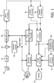
- FIGURE 1 an ultrasonic diagnostic imaging system constructed in accordance with the principles of the present invention is shown in block diagram form.
- a transducer array 10' is provided in an ultrasound probe 10 for transmitting ultrasonic waves and receiving echo information.
- the transducer array 10' is preferably a two dimensional array of transducer elements capable of scanning in three dimensions, for instance, in both elevation and azimuth about the location of the mitral valve, for 3D imaging.
- the transducer array is coupled to a microbeamformer 12 in the probe which controls transmission and reception of signals by the array elements.
- Microbeamformers are capable of at least partial beamforming of the signals received by groups or "patches" of transducer elements as described in US Pats.
- the microbeamformer is coupled by the probe cable to a transmit/receive (T/R) switch 16 which switches between transmission and reception and protects the main beamformer 20 from high energy transmit signals.
- T/R transmit/receive
- the transmission of ultrasonic beams from the transducer array 10 under control of the microbeamformer 12 is directed by the transmit controller 18 coupled to the T/R switch and the beamformer 20, which receives input from the user's operation of the user interface or control panel 38.
- One of the functions controlled by the transmit controller is the direction in which beams are steered. Beams may be steered straight ahead from (orthogonal to) the transducer array, or at different angles for a wider field of view.
- the partially beamformed signals produced by the microbeamformer 12 are coupled to a main beamformer 20 where partially beamformed signals from the individual patches of elements are combined into a fully beamformed signal.
- the main beamformer 20 may have 128 channels, each of which receives a partially beamformed signal from a patch of 12 transducer elements. In this way the signals received by over 1500 transducer elements of a two dimensional array can contribute efficiently to a single beamformed signal.
- the beamformed signals are coupled to a signal processor 22.
- the signal processor 22 can process the received echo signals in various ways, such as bandpass filtering, decimation, I and Q component separation, and harmonic signal separation which acts to separate linear and nonlinear signals so as to enable the identification of nonlinear echo signals returned from tissue and microbubbles.
- the signal processor may also perform additional signal enhancement such as speckle reduction, signal compounding, and noise elimination.
- the processed signals are coupled to a B mode processor 26 and a Doppler processor 28.
- the B mode processor 26 employs amplitude detection for the imaging of structures in the body such as the tissue of the heart wall, the mitral valve, and blood cells.
- B mode images of structure of the body may be formed in either the harmonic mode or the fundamental mode or a combination of both as described in US Pat. 6,283,919 (Roundhill et al. ) and US Pat. 6,458,083 (Jago et al. )
- the Doppler processor 28 processes temporally distinct signals from tissue and blood flow for the detection of the motion of substances such as the flow of blood cells in the image field.
- the Doppler processor typically includes a wall filter with parameters which may be set to pass and/or reject echoes returned from selected types of materials in the body.
- the wall filter can be set to have a passband characteristic which passes signal of relatively low amplitude from higher velocity materials while rejecting relatively strong signals from lower or zero velocity material.
- This passband characteristic will pass signals from flowing blood while rejecting signals from nearby stationary or slowing moving objects such as the wall of the heart.
- An inverse characteristic would pass signals from moving tissue of the heart while rejecting blood flow signals for what is referred to as tissue Doppler imaging, detecting and depicting the motion of tissue.
- the Doppler processor receives and processes a sequence of temporally discrete echo signals from different points in an image field, the sequence of echoes from a particular point referred to as an ensemble.
- An ensemble of echoes received in rapid succession over a relatively short interval can be used to estimate the Doppler shift frequency of flowing blood, with the correspondence of the Doppler frequency to velocity indicating the blood flow velocity.
- An ensemble of echoes received over a longer period of time is used to estimate the velocity of slower flowing blood or slowly moving tissue.
- short ensemble lengths (fewer samples) are generally employed so that a high acquisition frame rate can be realized.
- the structural and motion signals produced by the B mode and Doppler processors are coupled to a scan converter 32 and a multiplanar reformatter 44.
- the scan converter arranges the echo signals in the spatial relationship from which they were received in a desired image format. For instance, the scan converter may arrange the echo signal into a two dimensional (2D) sector-shaped format, or a pyramidal three dimensional (3D) image.
- the scan converter can overlay a B mode structural image with colors corresponding to motion at points in the image field corresponding with their Doppler-estimated velocities to produce a color Doppler image which depicts the motion of tissue and blood flow in the image field.
- the multiplanar reformatter will convert echoes which are received from points in a common plane in a volumetric region of the body into an ultrasonic image of that plane, as described in US Pat. 6,443,896 (Detmer ).
- a volume renderer 42 converts the echo signals of a 3D data set into a projected 3D image as viewed from a given reference point as described in US Pat. 6,530,885 (Entrekin et al. )
- the 2D or 3D images are coupled from the scan converter 32, multiplanar reformatter 44, and volume renderer 42 to an image processor 30 for further enhancement, buffering and temporary storage for display on an image display 40.
- blood flow velocity values produced by the Doppler processor 28 are coupled to a flow quantification processor 34.
- the flow quantification processor operates as described below to produce a measure of the flow rate through a regurgitant orifice, the volume flow through the orifice, and the spatial location of the orifice.
- the flow quantification processor may receive input from the user control panel 38, such as an initial estimate of the location of the orifice as described below.
- Output data from the flow quantification processor is coupled to a graphics processor 36 for the reproduction of output data from the processor with the image on the display 40.
- the graphics processor 36 can also generate graphic overlays for display with the ultrasound images.
- These graphic overlays can contain standard identifying information such as patient name, date and time of the image, imaging parameters, and the like.
- the graphics processor receives input from the user interface 38, such as a typed patient name.
- the user interface is also coupled to the transmit controller 18 to control the generation of ultrasound signals from the transducer array 10' and hence the images produced by the transducer array and the ultrasound system.
- the user interface is also coupled to the multiplanar reformatter 44 for selection and control of a display of multiple multiplanar reformatted (MPR) images which may be used to quantify regurgitant flow in the MPR images in accordance with the present invention as described below.
- MPR multiplanar reformatted
- FIGURE 2 describes the operation of the flow quantification processor of FIGURE 1 .
- the processor is based upon a mathematical model of the flow velocity field at sample points within an inclusion zone as described below.
- the inclusion zone is preferably a curved strip delineated by two arcs centered on the regurgitant orifice location, ⁇ x o , y o , z o ⁇ .
- the curved strip is of the form of a hemispherical shell, as discussed in conjunction with FIGURE 3 below.
- the model can start with assumed or estimated values for the unknown parameters, including the flow F and the ⁇ x o , y o , z o ⁇ location of the regurgitant orifice.
- the model can start with parameters which are nominally characteristic of regurgitant flow.
- the user can enter parameters such as by indicating the presumed location of the regurgitant orifice in the ultrasound image. Or a known technique such as PISA can be used to calculate values used as the starting parameters for the flow velocity field.
- the flow velocity field model approximates velocity vectors which would be accurate if the true physiologic velocity vectors were known.
- the velocity vectors approximated by the model are indicated at the output of box 50 as ⁇ V TRUE .
- Box 52 then imposes some limits and adjustments to ⁇ V TRUE due to practical factors such as the physics of ultrasound and operating parameters of the ultrasound system being used.
- the flow velocity field model is then adjusted or scaled to take these practical factors into account in consideration of the actual velocity values which would be observed by an ultrasound system.
- One of the practical factors for which adjustment can be made is the Doppler angle. As mentioned above, Doppler measurements as performed by an ultrasound system are precisely accurate only when the direction of flow is in line with the direction of the ultrasound beam, a Doppler angle of zero.
- a Doppler wall filter will typically exhibit a nonlinear characteristic which, for blood flow detection, will have a zero response at DC (no motion) and rise to a maximum response at a selected high frequency of ⁇ f.
- the wall filter can exhibit a maximum response at a frequency less than that dictated by the Nyquist limit of the ensemble sampling rate, as discussed below.
- a sample volume in the body at which the Doppler shift is measured will not be a single point in the body but will have a finite size, resulting in the return of Doppler signals indicative of a range of velocities.
- the non-uniform response of the wall filter can cause a wide spread of velocities to experience greater gain at different locations of the response characteristic, e.g., higher velocities are more greatly emphasized than lower velocities.
- This non-uniform response can produce a shift in the perceived center of the spread of velocities referred to as wall filter bias.
- the wall filter bias effect can also be taken into account by an adjustment to the model.
- spectral spread the Doppler spectral broadening effect resulting from the different paths and angles from the sample volume to each receiving element of the active aperture of an array transducer. See US Pat. 5,606,972 (Routh ).
- aliasing effects the mis-reporting of Doppler frequencies and velocities when the motion of blood flow is at a velocity in excess of that which can be detected unambiguously by the Nyquist limit of the sampling rate of the echo ensemble.
- a comparator 54 compares the expected velocity values from the flow velocity field model, V OBS , with actual velocity measurements from points (sample volumes) in the field, V MEAS , produced by the Doppler processor 28.
- the differences between the expected and received values are squared to produce an error term for each point.
- the error terms are integrated over the full inclusion zone which may be a one dimensional ( e . g ., 1D line), two dimensional ( e . g ., 2D line arcuate area), or three dimensional ( e . g ., 3D hemispherical shell) inclusion zone to produce a mean squared error term form the full zone.
- the error term is then used to adjust the parameters of the field model such as r and the flow rate to cause a reduction in a subsequently measured error term.
- the preferred adjustment technique is to use a non-linear curve fit to adapt the model toward error reduction.
- One such non-linear curve fitting technique which may be used is the Levengerg-Marquardt algorithm, which refines the coordinates of the regurgitant orifice location and the flow ( F ) or flow rate (Q t ) of the field toward or through the orifice.
- the loop of FIGURE 2 is iteratively repeated to reduce the error term.
- a more precisely adapted field model is adjusted and compared with ultrasound velocity measurements from the acceptance zone and the error term is iteratively reduced.
- the model exhibits the desired actual measurements of the orifice location and the blood flow through the orifice.
- FIGURE 3 is a diagrammatic 2D ultrasound image illustrating practice of the present invention to measure mitral valve requrgitation.
- the line 100 represents the plane of the mitral valve on which a regurgitant leak exists through an orifice O.
- a jet of blood 102 escapes back into the right atria.
- this jet would be interrogated by a Doppler beam 110 extending through the orifice O.
- US Pat. 6,719,697 (Li ) presents an improvement to the PISA technique in which a color M mode display is produced over the the heart cycle from the location of Doppler beam 110.
- Aliasing occurs when a velocity being measured exceeds the Nyquist limits of +V and -V.
- FCR flow convergent region
- S acceptance zone 112
- Both the PISA technique and the present invention are premised on the assumption that the regurgitant flow in the left ventricle near the orifice is converging and flowing toward the orifice location O. This is indicated by the flow vectors V 1 , V 2 , and V 3 in the acceptance zone S. But as the direction of the Doppler beam 110 illustrates, virtually all of the flow vectors will not be aligned with the beam direction, even when the varying beam angles of a phased array sector probe are used. Consequently there will be Doppler angles of different magnitudes for the different flow vectors, which is taken into account by the Doppler angle adjustments to the flow velocity field model in box 52 of FIGURE 2 as described above.
- the color Doppler image of the FCR 104 will be chaotic and erratic. This is because the spatial orientation of blood cells and blood flow velocities are changing very rapidly in this region as blood flow changes direction and accelerates momentarily toward the orifice O during systolic contraction. The ensemble samples acquired during this interval are often uncorrelated with one another, which defeats the correlation within an ensemble upon which the usual Doppler estimation processors are reliant. As a result, even thought the flow within the FCR may be generally laminar, the colorflow display can be that of highly turbulent flow and aliasing.
- the inner boundary 108 of the acceptance zone S is preferably set beyond the flow convergence region 104 to avoid the use of erratic velocity estimates from the FCR.
- One approach to setting the boundary 108 is to set it at or beyond the velocity shear boundary. This can be done visually with reference to the colorflow display, or automatically with reference to a velocity shear threshold.
- the outer boundary 106 of the acceptance zone may be set in relation to measurable velocities. While the velocities of regurgitant flow are relatively high near the orifice, they become progressively lower at increasing distances from the orifice.
- the outer boundary 106 can be set at a distance from the orifice O at which low Doppler velocities can still be reliably measured. This may be determined in relation to a percentage of the Nyquist limit or in relation to a low flow velocity such as 5 mm/sec.
- the outer boundary 106 can thus be set at a distance at which acceptable sensitivity to low flows can still be realized by the Doppler processor.
- the acceptance zone 112 in the example of FIGURE 3 is seen to be a two dimensional arcuate area S having a center of rotation at the orifice O.
- the present invention may be used in one, two or three dimensions.
- a one dimensional implementation and model may just consider the segment of the beam line 110 which is between arcs 108 and 106, for instance.
- a two dimensional implementation would be one which samples an acceptance zone which is planar such as acceptance zone 112 in FIGURE 3 .
- a three dimensional implementation would consider an arcuate acceptance such as 112 but in a full hemisphere centered on the orifice. Greater accuracy would be anticipated with the two and three dimensional implementations.
- a preferred implementation would use a 3D imaging probe with a two dimensional array transducer as shown in FIGURE 1 , with acquisition and modeling done in a hemispherical or semi-hemispherical volume shell about the orifice.
- Higher frame rates can be realized with two dimensional imaging, in which case an MPR frame through the orifice and jet can be selected from the volume scanned with the 3D probe by use of the multiplanar reformatter 44.
- the desired plane can be repeatedly scanned at a high acquisition frame rate and the velocity measurements and flow calculations done with a two dimensional acceptance zone shown in the 2D MPR image.
- an acceptance zone may have a parabolic or flattened circular shape.
- the acceptance zone may be a paraboloid or oblate spheroid shell.
- the shape of the acceptance zone that is, the area or volume in which velocities are measured in comparison to the model, may be dynamically changed during iterative passages through the processing loop of FIGURE 2 so that the process will adapt and converge to an acceptance zone with an altered shape from that used in the initial model.
- FIGURE 4 illustrates an ultrasound image in which elements previously described in conjunction with FIGURE 3 bear the same reference numerals. This image also includes a small box 130 which has been placed over the image by a clinician at the start of a diagnosis to indicate the presumed location of the regurgitant orifice.
- a control of the control panel 38 such as the trackball is manipulated by the clinician to place the icon 130 at the location in the image where the clinician believes the orifice is located.
- the coordinates of the indicated orifice icon 130 are used to seed the processing of the flow quantification processor shown in FIGURE 2 , whereby the coordinates are used as the initial coordinates of the orifice in the mathematical model of box 50.
- the processor 34 iteratively refines the modeled values of the flow velocity vectors toward an orifice location in response to the receipt of the measured velocity values V MEAS .
- the vertical placement of the orifice location has been found to have the greatest effect on the convergence of the modeled velocity vectors with the measured velocity values.
- the processor 34 iteratively refines the location of the orifice to reduce the error disparity between the measured and estimated velocity values in the flow velocity field (acceptance zone S) between boundaries 106 and 108. As the flow quantification processor iterates to converge on the true coordinates of the orifice, the finally determined coordinates are used by the flow quantification processor 34 and the graphics processor 36 to automatically move orifice icon 130 to the calculated coordinates in the image.
- the graphics processor will place another (calculated) orifice icon 132 on the display at the true coordinate location determined by the iterative model adjustment.
- volume flow being the integral of the flow rate over the time during which the heart is contract (about 1/3 of a heart cycle).
- the flow volume will peak at approximately the middle of the systolic interval.
- FIGURE 4 it is seen that the system has placed the calculated orifice icon 132 at its true location in the image field, which is different from the clinician's initial estimate of the orifice location.
- the orifice coordinates When the ultrasound study is performed with 2D imaging the orifice coordinates will generally be in (x,y,z) Cartesian coordinates. When 3D imaging is used a spherical (r, ⁇ , ⁇ ) coordinate system will generally be employed.
- the acceptance zone S is graphically delineated in the displayed ultrasound image and any modification of the shape of the acceptance zone as discussed above is incorporated in the displayed shape and graphical delineation of the acceptance zone on the display.
- FIGURE 5 is an illustration of the use of an implementation of the present invention to asses the flow rate and volume flow of slits and multiple leaks in valve closure. As FIGURE 5 illustrates, the process of the present invention is performed for a series of orifice locations arrayed along the leaking mitral valve 100'. These discrete pinhole orifice locations can be used to model complex slit-like orifices or multiple orifices in the closed valve.
- FIGURE 5 shows an example of three such determinations, each with its own acceptance zone, indicated by outer zone boundaries 106, 106' and 106", and flow vectors (indicated by the small arrows) directed to converge at a different orifice location along the valve 100'.
- the vector velocity field associated with each pinhole orifice is combined vectorially with the other orifices, such that a single combined acceptance zone is defined along with a single combined vector velocity field.
- the combined vector velocity field now approximates the true physiologic velocity vectors ( ⁇ Vtrue, output of box 50 in FIGURE 2 ).
- the processing of the combined vector velocity field determines the flow rate or volume flow of all the pinhole orifices corresponding to the entire slit along the mitral valve closure.
- FIGURE 5 gives an example of a vector velocity field generated from three pinhole orifices
- any number of orifices may be used to adequately model the slit.
- the acceptance zones used for each measurement may be combined as shown in FIGURE 5 , as the flow that is determined for the combined orifices is vectorial flow directed toward a unique orifice or position along a slit.
- the line of measurements is not constrained to a straight line in a plane, but may follow a non-linear path of closure of the mitral valve leaflets.
- FIGURE 6 illustrates the response characteristics of two Doppler wall filters which may be employed in an implementation of the present invention.
- the coordinates of the abscissa of the plot of FIGURE 6 are in units of the Nyquist limits of a sampled data wall filter, where the limits of +1 and -1 are the normalized Nyquist limits of the filter corresponding to the blood flow velocities.
- a zero (DC, or no-flow) condition is in the center.
- the ordinate coordinates indicate the relative amplitude response of the filter characteristic.
- the response curve 140 is a typical wall filter response curve for measuring blood flow and may be used in an implementation of the present invention. This characteristic has a response of zero at the center, resulting in no response to stationary objects such as stationary vessel walls.
- the response is seen to progressively increase as the curve extends out from zero, with a maximum response at the Nyquist limits for the highest velocity flows detectable without aliasing at the chosen sampling interval. As a result, this response characteristic is most sensitive to flow at the highest flow velocities.
- the response curve 150 is one which is often preferred for the wall filter of an implementation of the present invention.
- the response of this curve 150 is seen to peak at a relatively high but intermediate sampling rate just above ⁇ 0.5 Nyquist, preferably in the range of 1 ⁇ 2 to 2/3 of Nyquist, and drops to a response of zero at the Nyquist limits.
- This filter characteristic is designed to be more sensitive to lower flow velocities, which can be expected around the outer boundary 106 of the acceptance zone S. This is helpful to offset the low sensitivity to low velocity flow which results from the short ensembles typically used for colorflow imaging of regurgitant flow. This can be seen by the greater response of the curve 150 for lower velocities near the center of the plot. While the curve 150 is seen to drop to zero at the Nyquist limits, this loss of high velocity sensitivity is generally acceptable when traded off for greater sensitivity to low velocity flows.
Landscapes
- Health & Medical Sciences (AREA)
- Life Sciences & Earth Sciences (AREA)
- Engineering & Computer Science (AREA)
- Heart & Thoracic Surgery (AREA)
- Molecular Biology (AREA)
- Nuclear Medicine, Radiotherapy & Molecular Imaging (AREA)
- Pathology (AREA)
- Radiology & Medical Imaging (AREA)
- Physics & Mathematics (AREA)
- Biomedical Technology (AREA)
- Veterinary Medicine (AREA)
- Medical Informatics (AREA)
- Biophysics (AREA)
- Surgery (AREA)
- Animal Behavior & Ethology (AREA)
- General Health & Medical Sciences (AREA)
- Public Health (AREA)
- Computer Vision & Pattern Recognition (AREA)
- Hematology (AREA)
- Physiology (AREA)
- Gynecology & Obstetrics (AREA)
- Ultra Sonic Daignosis Equipment (AREA)
Claims (15)
- Verfahren zum Messen einer Regurgitationsströmung aus mehreren oder schlitzförmigen Öffnungen, umfassend:Identifizieren eines ersten Öffnungsorts der Regurgitationsströmung;Erfassen von Ultraschallechosignalen in der Nähe des ersten Öffnungsorts;Verarbeiten der Echosignale, um ein Vektorgeschwindigkeitsfeld der Regurgitationsströmung durch den ersten Öffnungsort zu ermitteln;Identifizieren eines zweiten Öffnungsorts der Regurgitationsströmung;Erfassen von Ultraschallechosignalen in der Nähe des zweiten Öffnungsorts;Verarbeiten der Echosignale, um ein Vektorgeschwindigkeitsfeld der Regurgitationsströmung durch den zweiten Öffnungsort zu ermitteln; undvektorielles Kombinieren der Vektorgeschwindigkeitsfelder der Regurgitationsströmung durch die beiden Öffnungsorte, um dadurch ein einzelnes kombiniertes Vektorgeschwindigkeitsfeld zu definieren.
- Verfahren nach Anspruch 1, wobei der erste Verarbeitungsschritt weiterhin Doppler-Verarbeitung der Echosignale umfasst, um Strömungsvektoren zu dem ersten Öffnungsort hin zu identifizieren; und
wobei der zweite Verarbeitungsschritt weiterhin Doppler-Verarbeitung der Echosignale umfasst, um Strömungsvektoren zu dem zweiten Öffnungsort hin zu identifizieren. - Verfahren nach Anspruch 1, wobei der erste Erfassungsschritt weiterhin das Erfassen von Ultraschallechosignalen aus einer zweidimensionalen Akzeptanzzone proximal zu dem ersten Öffnungsort umfasst; und
wobei der zweite Erfassungsschritt weiterhin das Erfassen von Ultraschallechosignalen aus einer zweidimensionalen Akzeptanzzone proximal zu dem zweiten Öffnungsort umfasst. - Verfahren nach Anspruch 3, wobei jede Akzeptanzzone bogenförmig ist und einen Krümmungsmittelpunkt im Wesentlichen an dem ersten oder dem zweiten Öffnungsort hat.
- Verfahren nach Anspruch 3, wobei sich die beiden Akzeptanzzonen räumlich überlappen.
- Verfahren nach Anspruch 1, wobei der erste Erfassungsschritt weiterhin das Erfassen von Ultraschallechosignalen aus einer dreidimensionalen Akzeptanzzone proximal zu dem ersten Öffnungsort umfasst; und
wobei der zweite Erfassungsschritt weiterhin das Erfassen von Ultraschallechosignalen aus einer dreidimensionalen Akzeptanzzone proximal zu dem zweiten Öffnungsort umfasst. - Verfahren nach Anspruch 6, wobei jede Akzeptanzzone eine hemisphärische Form mit einem Krümmungsmittelpunkt im Wesentlichen an dem ersten oder dem zweiten Öffnungsort hat.
- Verfahren nach Anspruch 6, wobei sich die beiden Akzeptanzzonen räumlich überlappen.
- Verfahren nach Anspruch 1, wobei der erste und der zweite Öffnungsort jeweils den Ort eines Nadellochlecks einer geschlossenen Mitralklappe umfassen.
- Verfahren nach Anspruch 1, wobei der erste und der zweite Öffnungsort jeweils einen Ort eines schlitzförmigen Lecks einer geschlossenen Mitralklappe umfassen.
- Verfahren nach Anspruch 1, weiterhin umfassend das Anzeigen des einzelnen kombinierten Vektorgeschwindigkeitsfelds.
- Diagnostisches Ultraschallsystem zum Messen von Regurgitationsströmung aus mehreren oder schlitzförmigen Öffnungen, umfassend:eine Ultraschallsonde (10) mit einem Wandlerarray (10') zum Aussenden von Ultraschallenergie an und zum Empfangen von Ultraschallechos aus einer Vielzahl von Orten der Regurgitationsströmung in einem Körper;einen Bildprozessor (30), der auf die empfangenen Echos reagiert, um ein Ultraschallbild der identifizierten ersten und zweiten Orte der Regurgitationsströmung zu erzeugen;einen Doppler-Prozessor (28), der auf die empfangenen Echos aus der Nähe von jedem identifizierten Ort reagiert, um Doppler-Ultraschallmessungen der Blutströmungsgeschwindigkeit in der Nähe von jedem der identifizierten Orte zu erzeugen;einen Strömungsquantifizierungsprozessor (34), wobei die durch den Doppler-Prozessor (28) erzeugten Blutströmungsgeschwindigkeitswerte mit dem genannten Strömungsquantifizierungsprozessor (34) gekoppelt werden, der konfiguriert ist, um eine Vektorgeschwindigkeit der Regurgitationsströmung in der Nähe von jedem der identifizierten Orte zu ermitteln und die Vektorgeschwindigkeitsfelder der Regurgitationsströmung für die identifizierten Orte vektoriell zu kombinieren, um ein einzelnes kombiniertes Vektorgeschwindigkeitsfeld zu definieren; undeine Anzeigevorrichtung (40), die mit dem Bildprozessor (30) und dem Strömungsquantifizierungsprozessor (34) gekoppelt ist, um das Ultraschallbild der identifizierten Orte der Regurgitationsströmung und des einzelnen kombinierten Vektorgeschwindigkeitsfelds anzuzeigen.
- Diagnostisches Ultraschallsystem nach Anspruch 12, wobei jedes Vektorgeschwindigkeitsfeld Strömungsvektoren enthält, die sich auf einen spezifischen Öffnungsort beziehen.
- Diagnostisches Ultraschallsystem nach Anspruch 12, wobei jedes Vektorgeschwindigkeitsfeld zweidimensional ist.
- Diagnostisches Ultraschallsystem nach Anspruch 12, wobei jedes Vektorgeschwindigkeitsfeld dreidimensional ist.
Applications Claiming Priority (3)
| Application Number | Priority Date | Filing Date | Title |
|---|---|---|---|
| US201061426669P | 2010-12-23 | 2010-12-23 | |
| US201161466048P | 2011-03-22 | 2011-03-22 | |
| PCT/IB2011/055703 WO2012085778A1 (en) | 2010-12-23 | 2011-12-15 | Analysis of mitral regurgitation from slit orifices by ultrasonic imaging |
Publications (2)
| Publication Number | Publication Date |
|---|---|
| EP2654571A1 EP2654571A1 (de) | 2013-10-30 |
| EP2654571B1 true EP2654571B1 (de) | 2017-07-26 |
Family
ID=45529148
Family Applications (1)
| Application Number | Title | Priority Date | Filing Date |
|---|---|---|---|
| EP11811570.8A Not-in-force EP2654571B1 (de) | 2010-12-23 | 2011-12-15 | Analyse von mitralinsuffizienz aus schlitzförmigen öffnungen mittels ultraschallbildgebung |
Country Status (7)
| Country | Link |
|---|---|
| US (1) | US10463341B2 (de) |
| EP (1) | EP2654571B1 (de) |
| JP (1) | JP5997177B2 (de) |
| CN (1) | CN103391748B (de) |
| BR (1) | BR112013015628A2 (de) |
| RU (1) | RU2596722C2 (de) |
| WO (1) | WO2012085778A1 (de) |
Families Citing this family (10)
| Publication number | Priority date | Publication date | Assignee | Title |
|---|---|---|---|---|
| DE102008053073B4 (de) * | 2008-10-24 | 2010-08-05 | Tomtec Imaging Systems Gmbh | Dreidimensionale Ableitung einer proximalen isokinetischen Schale einer proximalen Flusskonvergenzzonze sowie dreidimensionale PISA-Flussmessung |
| JP5997177B2 (ja) | 2010-12-23 | 2016-09-28 | コーニンクレッカ フィリップス エヌ ヴェKoninklijke Philips N.V. | 超音波撮像によるスリット開口部からの僧帽弁逆流の解析 |
| EP3469553A1 (de) * | 2016-06-10 | 2019-04-17 | Koninklijke Philips N.V. | Systeme und verfahren zur erzeugung von b-modus-bildern aus 3d-ultraschalldaten |
| EP3692925A1 (de) * | 2019-02-11 | 2020-08-12 | Koninklijke Philips N.V. | Verfahren und systeme zur herzklappenregurgitationsbewertung |
| CN115670511A (zh) * | 2021-07-23 | 2023-02-03 | 深圳迈瑞生物医疗电子股份有限公司 | 基于超声的血流测量方法和超声成像系统 |
| CN115670513A (zh) * | 2021-07-23 | 2023-02-03 | 深圳迈瑞生物医疗电子股份有限公司 | 基于超声的血流测量方法和超声成像系统 |
| EP4137061A1 (de) * | 2021-08-17 | 2023-02-22 | Koninklijke Philips N.V. | Ultraschallbildgebung zur visualisierung und quantifizierung von mitralinsuffizienz |
| CN117197020B (zh) * | 2022-05-23 | 2025-07-18 | 上海微创卜算子医疗科技有限公司 | 二尖瓣开口间距检测方法、电子设备和存储介质 |
| CN115177288B (zh) * | 2022-06-22 | 2025-08-08 | 中国人民解放军北部战区总医院 | 二尖瓣反流频谱包络线识别方法和左房压测定方法 |
| CN115587992B (zh) * | 2022-10-21 | 2025-06-10 | 复旦大学附属中山医院 | 房室瓣反流容积m型pisa定量方法以及电子设备 |
Family Cites Families (24)
| Publication number | Priority date | Publication date | Assignee | Title |
|---|---|---|---|---|
| US5062427A (en) * | 1988-05-06 | 1991-11-05 | Kabushiki Kaisha Toshiba | Ultrasonic doppler apparatus |
| US4913159A (en) | 1989-03-17 | 1990-04-03 | Hitachi Medial Corp. | Method for determining blood flow through a narrowed orifice using color doppler echocardiography |
| US5285788A (en) * | 1992-10-16 | 1994-02-15 | Acuson Corporation | Ultrasonic tissue imaging method and apparatus with doppler velocity and acceleration processing |
| US5899861A (en) * | 1995-03-31 | 1999-05-04 | Siemens Medical Systems, Inc. | 3-dimensional volume by aggregating ultrasound fields of view |
| US5606972A (en) | 1995-08-10 | 1997-03-04 | Advanced Technology Laboratories, Inc. | Ultrasonic doppler measurement of blood flow velocities by array transducers |
| US6283919B1 (en) | 1996-11-26 | 2001-09-04 | Atl Ultrasound | Ultrasonic diagnostic imaging with blended tissue harmonic signals |
| US6458083B1 (en) | 1996-11-26 | 2002-10-01 | Koninklijke Philips Electronics N.V. | Ultrasonic harmonic imaging with adaptive image formation |
| US6013032A (en) | 1998-03-13 | 2000-01-11 | Hewlett-Packard Company | Beamforming methods and apparatus for three-dimensional ultrasound imaging using two-dimensional transducer array |
| US5997479A (en) | 1998-05-28 | 1999-12-07 | Hewlett-Packard Company | Phased array acoustic systems with intra-group processors |
| RU2187239C2 (ru) * | 1999-11-16 | 2002-08-20 | Костылев Александр Николаевич | Способ прогнозирования циркуляторных нарушений головного мозга при интубации трахеи и в течение анестезии |
| US6530885B1 (en) | 2000-03-17 | 2003-03-11 | Atl Ultrasound, Inc. | Spatially compounded three dimensional ultrasonic images |
| US6464637B1 (en) * | 2000-06-23 | 2002-10-15 | Koninklijke Philips Electronics N.V. | Automatic flow angle correction by ultrasonic vector |
| US6443896B1 (en) | 2000-08-17 | 2002-09-03 | Koninklijke Philips Electronics N.V. | Method for creating multiplanar ultrasonic images of a three dimensional object |
| US6468216B1 (en) | 2000-08-24 | 2002-10-22 | Kininklijke Philips Electronics N.V. | Ultrasonic diagnostic imaging of the coronary arteries |
| US6719697B2 (en) * | 2001-02-27 | 2004-04-13 | Koninklijke Philips Electronics N.V. | Ultrasonic quantification of valvular regurgitant blood flow |
| AU2002353325A1 (en) * | 2001-12-28 | 2003-07-30 | Koninklijke Philips Electronics N.V. | Viewing system having means for processing a sequence of ultrasound images for performing a quantitative estimation of a flow in a body organ |
| JP4269623B2 (ja) * | 2002-10-07 | 2009-05-27 | 株式会社 東北テクノアーチ | 血流可視化診断装置 |
| EP1601291A1 (de) | 2003-02-27 | 2005-12-07 | Universität Duisburg-Essen | Methode und gerät zur bestimmung des blutflusses mittels ultraschall |
| US8355548B2 (en) * | 2005-09-29 | 2013-01-15 | Washington University | Load independent index of diastolic function |
| US9612142B2 (en) * | 2006-04-27 | 2017-04-04 | General Electric Company | Method and system for measuring flow through a heart valve |
| CN101636113B (zh) * | 2007-04-27 | 2011-09-21 | 株式会社日立医药 | 超声波诊断装置 |
| US20090043208A1 (en) * | 2007-08-10 | 2009-02-12 | Norwegian University Of Science And Technology | Methods and devices for estimating blood flow characteristics |
| US9204858B2 (en) * | 2010-02-05 | 2015-12-08 | Ultrasonix Medical Corporation | Ultrasound pulse-wave doppler measurement of blood flow velocity and/or turbulence |
| JP5997177B2 (ja) | 2010-12-23 | 2016-09-28 | コーニンクレッカ フィリップス エヌ ヴェKoninklijke Philips N.V. | 超音波撮像によるスリット開口部からの僧帽弁逆流の解析 |
-
2011
- 2011-12-15 JP JP2013545579A patent/JP5997177B2/ja not_active Expired - Fee Related
- 2011-12-15 WO PCT/IB2011/055703 patent/WO2012085778A1/en not_active Ceased
- 2011-12-15 EP EP11811570.8A patent/EP2654571B1/de not_active Not-in-force
- 2011-12-15 RU RU2013134355/14A patent/RU2596722C2/ru not_active IP Right Cessation
- 2011-12-15 CN CN201180068135.6A patent/CN103391748B/zh not_active Expired - Fee Related
- 2011-12-15 BR BR112013015628A patent/BR112013015628A2/pt not_active Application Discontinuation
- 2011-12-15 US US13/991,551 patent/US10463341B2/en active Active
Non-Patent Citations (1)
| Title |
|---|
| None * |
Also Published As
| Publication number | Publication date |
|---|---|
| EP2654571A1 (de) | 2013-10-30 |
| CN103391748B (zh) | 2016-03-02 |
| JP2014500117A (ja) | 2014-01-09 |
| CN103391748A (zh) | 2013-11-13 |
| BR112013015628A2 (pt) | 2016-10-11 |
| RU2013134355A (ru) | 2015-01-27 |
| US20130261458A1 (en) | 2013-10-03 |
| JP5997177B2 (ja) | 2016-09-28 |
| US10463341B2 (en) | 2019-11-05 |
| RU2596722C2 (ru) | 2016-09-10 |
| WO2012085778A1 (en) | 2012-06-28 |
Similar Documents
| Publication | Publication Date | Title |
|---|---|---|
| EP2654571B1 (de) | Analyse von mitralinsuffizienz aus schlitzförmigen öffnungen mittels ultraschallbildgebung | |
| EP2654570B1 (de) | Analyse von mitralinsuffizienz durch ultraschallbildgebung | |
| EP2654573B1 (de) | Automatisierte identifizierung der position einer regurgitationsöffnung einer mitralklappe auf einem ultraschallbild | |
| US10512444B2 (en) | Ultrasonic color flow map for analysis of mitral regurgitation | |
| JP2007509722A (ja) | 超音波流体の流動中心線を決定するための方法および装置 | |
| EP2654569B1 (de) | Wandfilter für ultraschallanalyse von mitralinsuffizienz | |
| EP4142605A1 (de) | Dreidimensionaler farbdoppler zur ultraschall-volumendurchflussmessung | |
| US20230329670A1 (en) | Ultrasonic measurement of vessel stenosis |
Legal Events
| Date | Code | Title | Description |
|---|---|---|---|
| PUAI | Public reference made under article 153(3) epc to a published international application that has entered the european phase |
Free format text: ORIGINAL CODE: 0009012 |
|
| 17P | Request for examination filed |
Effective date: 20130723 |
|
| AK | Designated contracting states |
Kind code of ref document: A1 Designated state(s): AL AT BE BG CH CY CZ DE DK EE ES FI FR GB GR HR HU IE IS IT LI LT LU LV MC MK MT NL NO PL PT RO RS SE SI SK SM TR |
|
| DAX | Request for extension of the european patent (deleted) | ||
| 17Q | First examination report despatched |
Effective date: 20151028 |
|
| GRAP | Despatch of communication of intention to grant a patent |
Free format text: ORIGINAL CODE: EPIDOSNIGR1 |
|
| INTG | Intention to grant announced |
Effective date: 20170217 |
|
| RIN1 | Information on inventor provided before grant (corrected) |
Inventor name: YAP, CHOON-HWAI Inventor name: WEI, QIFENG Inventor name: THIELE, KARL E. Inventor name: YOGANATHAN, AJIT, P. |
|
| GRAS | Grant fee paid |
Free format text: ORIGINAL CODE: EPIDOSNIGR3 |
|
| GRAA | (expected) grant |
Free format text: ORIGINAL CODE: 0009210 |
|
| AK | Designated contracting states |
Kind code of ref document: B1 Designated state(s): AL AT BE BG CH CY CZ DE DK EE ES FI FR GB GR HR HU IE IS IT LI LT LU LV MC MK MT NL NO PL PT RO RS SE SI SK SM TR |
|
| REG | Reference to a national code |
Ref country code: GB Ref legal event code: FG4D |
|
| REG | Reference to a national code |
Ref country code: CH Ref legal event code: EP |
|
| REG | Reference to a national code |
Ref country code: AT Ref legal event code: REF Ref document number: 911728 Country of ref document: AT Kind code of ref document: T Effective date: 20170815 |
|
| REG | Reference to a national code |
Ref country code: IE Ref legal event code: FG4D |
|
| REG | Reference to a national code |
Ref country code: DE Ref legal event code: R096 Ref document number: 602011040000 Country of ref document: DE |
|
| REG | Reference to a national code |
Ref country code: DE Ref legal event code: R084 Ref document number: 602011040000 Country of ref document: DE |
|
| REG | Reference to a national code |
Ref country code: NL Ref legal event code: MP Effective date: 20170726 |
|
| REG | Reference to a national code |
Ref country code: LT Ref legal event code: MG4D |
|
| REG | Reference to a national code |
Ref country code: AT Ref legal event code: MK05 Ref document number: 911728 Country of ref document: AT Kind code of ref document: T Effective date: 20170726 |
|
| REG | Reference to a national code |
Ref country code: FR Ref legal event code: PLFP Year of fee payment: 7 |
|
| PG25 | Lapsed in a contracting state [announced via postgrant information from national office to epo] |
Ref country code: SE Free format text: LAPSE BECAUSE OF FAILURE TO SUBMIT A TRANSLATION OF THE DESCRIPTION OR TO PAY THE FEE WITHIN THE PRESCRIBED TIME-LIMIT Effective date: 20170726 Ref country code: LT Free format text: LAPSE BECAUSE OF FAILURE TO SUBMIT A TRANSLATION OF THE DESCRIPTION OR TO PAY THE FEE WITHIN THE PRESCRIBED TIME-LIMIT Effective date: 20170726 Ref country code: NL Free format text: LAPSE BECAUSE OF FAILURE TO SUBMIT A TRANSLATION OF THE DESCRIPTION OR TO PAY THE FEE WITHIN THE PRESCRIBED TIME-LIMIT Effective date: 20170726 Ref country code: NO Free format text: LAPSE BECAUSE OF FAILURE TO SUBMIT A TRANSLATION OF THE DESCRIPTION OR TO PAY THE FEE WITHIN THE PRESCRIBED TIME-LIMIT Effective date: 20171026 Ref country code: HR Free format text: LAPSE BECAUSE OF FAILURE TO SUBMIT A TRANSLATION OF THE DESCRIPTION OR TO PAY THE FEE WITHIN THE PRESCRIBED TIME-LIMIT Effective date: 20170726 Ref country code: AT Free format text: LAPSE BECAUSE OF FAILURE TO SUBMIT A TRANSLATION OF THE DESCRIPTION OR TO PAY THE FEE WITHIN THE PRESCRIBED TIME-LIMIT Effective date: 20170726 Ref country code: FI Free format text: LAPSE BECAUSE OF FAILURE TO SUBMIT A TRANSLATION OF THE DESCRIPTION OR TO PAY THE FEE WITHIN THE PRESCRIBED TIME-LIMIT Effective date: 20170726 |
|
| PG25 | Lapsed in a contracting state [announced via postgrant information from national office to epo] |
Ref country code: BG Free format text: LAPSE BECAUSE OF FAILURE TO SUBMIT A TRANSLATION OF THE DESCRIPTION OR TO PAY THE FEE WITHIN THE PRESCRIBED TIME-LIMIT Effective date: 20171026 Ref country code: ES Free format text: LAPSE BECAUSE OF FAILURE TO SUBMIT A TRANSLATION OF THE DESCRIPTION OR TO PAY THE FEE WITHIN THE PRESCRIBED TIME-LIMIT Effective date: 20170726 Ref country code: IS Free format text: LAPSE BECAUSE OF FAILURE TO SUBMIT A TRANSLATION OF THE DESCRIPTION OR TO PAY THE FEE WITHIN THE PRESCRIBED TIME-LIMIT Effective date: 20171126 Ref country code: RS Free format text: LAPSE BECAUSE OF FAILURE TO SUBMIT A TRANSLATION OF THE DESCRIPTION OR TO PAY THE FEE WITHIN THE PRESCRIBED TIME-LIMIT Effective date: 20170726 Ref country code: PL Free format text: LAPSE BECAUSE OF FAILURE TO SUBMIT A TRANSLATION OF THE DESCRIPTION OR TO PAY THE FEE WITHIN THE PRESCRIBED TIME-LIMIT Effective date: 20170726 Ref country code: GR Free format text: LAPSE BECAUSE OF FAILURE TO SUBMIT A TRANSLATION OF THE DESCRIPTION OR TO PAY THE FEE WITHIN THE PRESCRIBED TIME-LIMIT Effective date: 20171027 Ref country code: LV Free format text: LAPSE BECAUSE OF FAILURE TO SUBMIT A TRANSLATION OF THE DESCRIPTION OR TO PAY THE FEE WITHIN THE PRESCRIBED TIME-LIMIT Effective date: 20170726 |
|
| PG25 | Lapsed in a contracting state [announced via postgrant information from national office to epo] |
Ref country code: RO Free format text: LAPSE BECAUSE OF FAILURE TO SUBMIT A TRANSLATION OF THE DESCRIPTION OR TO PAY THE FEE WITHIN THE PRESCRIBED TIME-LIMIT Effective date: 20170726 Ref country code: CZ Free format text: LAPSE BECAUSE OF FAILURE TO SUBMIT A TRANSLATION OF THE DESCRIPTION OR TO PAY THE FEE WITHIN THE PRESCRIBED TIME-LIMIT Effective date: 20170726 Ref country code: DK Free format text: LAPSE BECAUSE OF FAILURE TO SUBMIT A TRANSLATION OF THE DESCRIPTION OR TO PAY THE FEE WITHIN THE PRESCRIBED TIME-LIMIT Effective date: 20170726 |
|
| REG | Reference to a national code |
Ref country code: DE Ref legal event code: R097 Ref document number: 602011040000 Country of ref document: DE |
|
| PG25 | Lapsed in a contracting state [announced via postgrant information from national office to epo] |
Ref country code: SM Free format text: LAPSE BECAUSE OF FAILURE TO SUBMIT A TRANSLATION OF THE DESCRIPTION OR TO PAY THE FEE WITHIN THE PRESCRIBED TIME-LIMIT Effective date: 20170726 Ref country code: EE Free format text: LAPSE BECAUSE OF FAILURE TO SUBMIT A TRANSLATION OF THE DESCRIPTION OR TO PAY THE FEE WITHIN THE PRESCRIBED TIME-LIMIT Effective date: 20170726 Ref country code: SK Free format text: LAPSE BECAUSE OF FAILURE TO SUBMIT A TRANSLATION OF THE DESCRIPTION OR TO PAY THE FEE WITHIN THE PRESCRIBED TIME-LIMIT Effective date: 20170726 |
|
| PLBE | No opposition filed within time limit |
Free format text: ORIGINAL CODE: 0009261 |
|
| STAA | Information on the status of an ep patent application or granted ep patent |
Free format text: STATUS: NO OPPOSITION FILED WITHIN TIME LIMIT |
|
| 26N | No opposition filed |
Effective date: 20180430 |
|
| REG | Reference to a national code |
Ref country code: CH Ref legal event code: PL |
|
| GBPC | Gb: european patent ceased through non-payment of renewal fee |
Effective date: 20171215 |
|
| PG25 | Lapsed in a contracting state [announced via postgrant information from national office to epo] |
Ref country code: SI Free format text: LAPSE BECAUSE OF FAILURE TO SUBMIT A TRANSLATION OF THE DESCRIPTION OR TO PAY THE FEE WITHIN THE PRESCRIBED TIME-LIMIT Effective date: 20170726 |
|
| REG | Reference to a national code |
Ref country code: IE Ref legal event code: MM4A |
|
| PG25 | Lapsed in a contracting state [announced via postgrant information from national office to epo] |
Ref country code: MT Free format text: LAPSE BECAUSE OF NON-PAYMENT OF DUE FEES Effective date: 20171215 Ref country code: LU Free format text: LAPSE BECAUSE OF NON-PAYMENT OF DUE FEES Effective date: 20171215 |
|
| REG | Reference to a national code |
Ref country code: BE Ref legal event code: MM Effective date: 20171231 |
|
| PG25 | Lapsed in a contracting state [announced via postgrant information from national office to epo] |
Ref country code: IE Free format text: LAPSE BECAUSE OF NON-PAYMENT OF DUE FEES Effective date: 20171215 |
|
| PG25 | Lapsed in a contracting state [announced via postgrant information from national office to epo] |
Ref country code: GB Free format text: LAPSE BECAUSE OF NON-PAYMENT OF DUE FEES Effective date: 20171215 Ref country code: LI Free format text: LAPSE BECAUSE OF NON-PAYMENT OF DUE FEES Effective date: 20171231 Ref country code: CH Free format text: LAPSE BECAUSE OF NON-PAYMENT OF DUE FEES Effective date: 20171231 Ref country code: BE Free format text: LAPSE BECAUSE OF NON-PAYMENT OF DUE FEES Effective date: 20171231 |
|
| PG25 | Lapsed in a contracting state [announced via postgrant information from national office to epo] |
Ref country code: HU Free format text: LAPSE BECAUSE OF FAILURE TO SUBMIT A TRANSLATION OF THE DESCRIPTION OR TO PAY THE FEE WITHIN THE PRESCRIBED TIME-LIMIT; INVALID AB INITIO Effective date: 20111215 Ref country code: MC Free format text: LAPSE BECAUSE OF FAILURE TO SUBMIT A TRANSLATION OF THE DESCRIPTION OR TO PAY THE FEE WITHIN THE PRESCRIBED TIME-LIMIT Effective date: 20170726 |
|
| PG25 | Lapsed in a contracting state [announced via postgrant information from national office to epo] |
Ref country code: CY Free format text: LAPSE BECAUSE OF NON-PAYMENT OF DUE FEES Effective date: 20170726 |
|
| PG25 | Lapsed in a contracting state [announced via postgrant information from national office to epo] |
Ref country code: MK Free format text: LAPSE BECAUSE OF FAILURE TO SUBMIT A TRANSLATION OF THE DESCRIPTION OR TO PAY THE FEE WITHIN THE PRESCRIBED TIME-LIMIT Effective date: 20170726 |
|
| PGFP | Annual fee paid to national office [announced via postgrant information from national office to epo] |
Ref country code: FR Payment date: 20191230 Year of fee payment: 9 |
|
| PG25 | Lapsed in a contracting state [announced via postgrant information from national office to epo] |
Ref country code: TR Free format text: LAPSE BECAUSE OF FAILURE TO SUBMIT A TRANSLATION OF THE DESCRIPTION OR TO PAY THE FEE WITHIN THE PRESCRIBED TIME-LIMIT Effective date: 20170726 |
|
| PGFP | Annual fee paid to national office [announced via postgrant information from national office to epo] |
Ref country code: IT Payment date: 20191223 Year of fee payment: 9 Ref country code: DE Payment date: 20191230 Year of fee payment: 9 |
|
| PG25 | Lapsed in a contracting state [announced via postgrant information from national office to epo] |
Ref country code: PT Free format text: LAPSE BECAUSE OF FAILURE TO SUBMIT A TRANSLATION OF THE DESCRIPTION OR TO PAY THE FEE WITHIN THE PRESCRIBED TIME-LIMIT Effective date: 20170726 |
|
| PG25 | Lapsed in a contracting state [announced via postgrant information from national office to epo] |
Ref country code: AL Free format text: LAPSE BECAUSE OF FAILURE TO SUBMIT A TRANSLATION OF THE DESCRIPTION OR TO PAY THE FEE WITHIN THE PRESCRIBED TIME-LIMIT Effective date: 20170726 |
|
| REG | Reference to a national code |
Ref country code: DE Ref legal event code: R119 Ref document number: 602011040000 Country of ref document: DE |
|
| PG25 | Lapsed in a contracting state [announced via postgrant information from national office to epo] |
Ref country code: FR Free format text: LAPSE BECAUSE OF NON-PAYMENT OF DUE FEES Effective date: 20201231 Ref country code: IT Free format text: LAPSE BECAUSE OF NON-PAYMENT OF DUE FEES Effective date: 20201215 |
|
| PG25 | Lapsed in a contracting state [announced via postgrant information from national office to epo] |
Ref country code: DE Free format text: LAPSE BECAUSE OF NON-PAYMENT OF DUE FEES Effective date: 20210701 |