EP2654860B1 - Unité de couvercle destinée à être utilisée lors de l'introduction d'un dispositif de piqûre dans une structure anatomique telle qu'une veine ou une artère et à maintenir ledit dispositif de piqûre dans la structure anatomique - Google Patents
Unité de couvercle destinée à être utilisée lors de l'introduction d'un dispositif de piqûre dans une structure anatomique telle qu'une veine ou une artère et à maintenir ledit dispositif de piqûre dans la structure anatomique Download PDFInfo
- Publication number
- EP2654860B1 EP2654860B1 EP11850251.7A EP11850251A EP2654860B1 EP 2654860 B1 EP2654860 B1 EP 2654860B1 EP 11850251 A EP11850251 A EP 11850251A EP 2654860 B1 EP2654860 B1 EP 2654860B1
- Authority
- EP
- European Patent Office
- Prior art keywords
- cover unit
- barrier member
- patient
- film
- barrier
- Prior art date
- Legal status (The legal status is an assumption and is not a legal conclusion. Google has not performed a legal analysis and makes no representation as to the accuracy of the status listed.)
- Active
Links
Images




Classifications
-
- A—HUMAN NECESSITIES
- A61—MEDICAL OR VETERINARY SCIENCE; HYGIENE
- A61M—DEVICES FOR INTRODUCING MEDIA INTO, OR ONTO, THE BODY; DEVICES FOR TRANSDUCING BODY MEDIA OR FOR TAKING MEDIA FROM THE BODY; DEVICES FOR PRODUCING OR ENDING SLEEP OR STUPOR
- A61M25/00—Catheters; Hollow probes
- A61M25/01—Introducing, guiding, advancing, emplacing or holding catheters
- A61M25/0105—Steering means as part of the catheter or advancing means; Markers for positioning
- A61M25/0108—Steering means as part of the catheter or advancing means; Markers for positioning using radio-opaque or ultrasound markers
-
- A—HUMAN NECESSITIES
- A61—MEDICAL OR VETERINARY SCIENCE; HYGIENE
- A61M—DEVICES FOR INTRODUCING MEDIA INTO, OR ONTO, THE BODY; DEVICES FOR TRANSDUCING BODY MEDIA OR FOR TAKING MEDIA FROM THE BODY; DEVICES FOR PRODUCING OR ENDING SLEEP OR STUPOR
- A61M25/00—Catheters; Hollow probes
- A61M25/01—Introducing, guiding, advancing, emplacing or holding catheters
- A61M25/02—Holding devices, e.g. on the body
-
- A—HUMAN NECESSITIES
- A61—MEDICAL OR VETERINARY SCIENCE; HYGIENE
- A61B—DIAGNOSIS; SURGERY; IDENTIFICATION
- A61B8/00—Diagnosis using ultrasonic, sonic or infrasonic waves
- A61B8/08—Clinical applications
- A61B8/0891—Clinical applications for diagnosis of blood vessels
-
- A—HUMAN NECESSITIES
- A61—MEDICAL OR VETERINARY SCIENCE; HYGIENE
- A61M—DEVICES FOR INTRODUCING MEDIA INTO, OR ONTO, THE BODY; DEVICES FOR TRANSDUCING BODY MEDIA OR FOR TAKING MEDIA FROM THE BODY; DEVICES FOR PRODUCING OR ENDING SLEEP OR STUPOR
- A61M25/00—Catheters; Hollow probes
- A61M25/01—Introducing, guiding, advancing, emplacing or holding catheters
- A61M25/02—Holding devices, e.g. on the body
- A61M2025/0266—Holding devices, e.g. on the body using pads, patches, tapes or the like
- A61M2025/0273—Holding devices, e.g. on the body using pads, patches, tapes or the like having slits to place the pad around a catheter puncturing site
Definitions
- the present invention relates to a cover unit for use when inserting a puncture device such as a cannula in an anatomical structure such as a vein or an artery and for maintaining said puncture device in the anatomical structure such as a vein or an artery.
- the present invention relates in particular to procedures involving visualisation using an ultrasonic device for the exact location for the puncture of the anatomical structure such as a vein or artery with a puncture device.
- Cannulas or other puncture devices are normally inserted into the vein or artery of the arms and legs with direct visualisation of the position of the vein or artery.
- the demand for sterility is small and thus, the skin is typically just washed or disinfected before the puncture.
- the puncture device is to be maintained in position after insertion. Therefore, a film is attached to the skin of the patient, close to the puncture site.
- the film often comprises an open-ended slit or a slot enabling the film to be arranged around the puncture device.
- the puncture device is maintained in the anatomical structure.
- a corresponding bandage with a slit and a thick absorbing pad at the puncture site is disclosed in WO93/00788 .
- the puncture site can be optimized and the target visualised using ultrasound.
- the target is precisely localised and the puncture device can be inserted optimally into the anatomical structure such as a vein or an artery.
- the position of the exact puncture site can be marked and the ultrasonic device removed before the puncture.
- minor movements of the patient often change the location for the exact procedure site.
- the use of real-time visualisation during the entire procedure is advantageous.
- Ultrasonic gel or similar contact means is needed to obtain a proper ultrasonic image. Applying ultrasonic gel to the skin of the patient, however, makes proper attachment of the film to the skin difficult after the insertion of the puncture device. Thus, the maintaining of the puncture device in a correct position is also impaired. Hereby, the puncture device may be displaced, detached or damage the anatomical structure. Furthermore, the non-sterile ultrasonic gel may pass the skin barrier and hereby contaminate the puncture site.
- a cover unit for use when inserting a puncture device such as a cannula in an anatomical structure such as a vein or an artery and for maintaining said puncture device in said anatomical structure, comprising a flexible film having a glue provided surface, and a removable covering layer to cover said glue provided surface and where said cover unit comprises
- This invention describes a cover unit for use in puncturing for targets in deeper anatomical structures by means of visualization techniques e.g. ultrasound for example at extremities e.g. arms and legs.
- the cover unit comprises a patient adherent member and a barrier member.
- a connection line divides the cover unit into the patient adherent member and a barrier member.
- the cover unit can be any shape, such as triangular, circular, rectangular, squared or curved.
- the patient adherent member can be any shape, such as triangular, circular, rectangular, squared or curved.
- the barrier member can be any shape, such as triangular, circular, rectangular, squared or curved. The shape of the patient adherent member and the barrier member is not necessarily similar.
- the patient adherent member is, in use, adhered to the skin of the patient, while the barrier member forms a barrier between the patient adherent member and the puncture site.
- the puncture site is to be interpreted as where the puncture device is to be inserted.
- the barrier member is preferably arranged in a substantially upright position.
- An upright position is to be interpreted as a position where easy access to the puncture site is obtained.
- the side of the barrier member with the puncture site forms a puncture procedure area, while the side of the barrier member facing the patient adherent member forms an ultrasound scanning area.
- a puncture procedure space is formed above the puncture procedure area being delimited by the barrier member.
- An ultrasound scanning space is formed above the ultrasound scanning area being delimited by the barrier member.
- a fixation plaster can be arranged on the skin by removing the cover unit along with the remains of the gel or other contact means. Hereby, the fixation plaster adheres properly to the skin of the patient.
- the barrier member is of a size that provides an efficient barrier between the ultrasound scanning area and the puncture procedure area.
- the barrier member prevents the gel or similar contact means from interacting with the puncture site. Penetration of the skin with for example a gel in connection with the puncturing can induce stings and pain as well as the gel can result in a toxic effect.
- the patient adherent member needs to be ultrasound transparent in order to obtain a proper ultrasonic signal.
- the patient adherent member needs only be ultrasound transparent in an area adjacent to the connection line in order for the puncture device to be properly inserted.
- An area adjacent to the connection line is here to be understood as the area where the ultrasound scanning is to be performed.
- the patient adherent member is not ultrasound transparent at least in the scanning area, an ultrasonic signal cannot be obtained and the anatomical structure cannot be visualised. Thus, the purpose of the cover unit cannot be fulfilled.
- connection line can be provided close to the edge of the cover unit for example providing a minor patient adherent member and a major barrier member.
- connection line is close to the middle of the cover unit, whereby the patient adherent member and the barrier member are substantially of similar size.
- the entire cover unit or parts hereof comprises a flexible film having a glue provided surface, and a removable covering layer to cover said glue provided surface.
- the barrier member comprises a flexible film having a glue provided surface, and a removable covering layer to cover said glue provided surface, while the patient adherent member is one adherent ultrasound transparent layer.
- the cover unit comprises a flexible film with a glue provided surface.
- the glue provided surface is covered by a removable covering layer when not in use.
- the covering layer or parts of the covering layer is removed from the glue provided surface when the cover unit is to be attached to the skin of a patient.
- the tearing strength between the film and the covering layer is characterised by leaving the glue on the film when removing the covering layer.
- the glue provided on the glue provided surface is to be a glue which is unable to contain air. Furthermore, the glue is unable to trap air. When attaching the film of the patient adherent member to the skin of the patient, no air will be contained between the film and the skin of the patient in the scanning area. Thus, the glue on the glue provided surface enables an ultrasonic signal to be transmitted. Any glue or adhesive, known to the person skilled in the art, capable of attaching a film to the skin of a patient and simultaneously being able to transmit an ultrasonic signal can be used.
- the glue provided on the flexible film of TegadermTM from 3MTM Minnesota Mining and Manufacturing Company can be used in this invention.
- the adhesive attaching the cover provided by Safersonictechnik GmbH g.m.b.H., Austria ( http://www.safersonic.com/en/productinfo/ ) to the ultrasound device can be provided as a glue in this invention.
- the glue provided on Steri-Drape from 3MTM Minnesota Mining and Manufacturing Company can be used in this invention.
- the glue provided on the barrier suction and diathermy bag from Molnlycke Health Care, Goteborg, Sweden can be used in this invention.
- the glue provided on the CVK kit operation Life II from H. Dam Kaergaard A/S, Denmark can be used in this invention. Any glue with characteristics similar to the characteristics of the glue as described in the examples can be used in the invention.
- a flexible film is to be understood as a film that comprises elasticity, extensibility and flexibility.
- the film is able to follow the movements of the skin and remain attached for a longer time.
- the film can be made of any ultrasonic transparent material for example plastic, rubber, paper or silicone.
- the film can be made of polyurethane, elastomeric polyesters or blends hereof.
- film is to be interpreted as any ultrasonic transparent material which can be adhered to the skin of a patient.
- the thickness of the film can vary depending on the specific characteristics of the material in order for the film to remain flexible as to accommodate the skin of the patient and not to affect the quality of the ultrasound image.
- the flexible film has a thickness of 10-45 microns.
- the cover unit comprises a patient adherent member and a barrier member connected along a connection line.
- the connection line is, in use, arranged close to the puncture side of the patient where the skin is punctured by a puncture device.
- a puncture device is for example a needle, catheter, a cannule, guidewires used for venous or arterial puncture or puncture of other anatomical structures.
- Patient includes humans as well as animals such as dogs, cats, horses, cattle etc.
- Anatomical structure includes for example a vein, an artery, a nerve, a tendon, a nerve sheat as well as tissues such as muscle, adipose tissue etc.
- connection line can be defined by a folding line for example if the barrier member and the patient adherent member are made in one piece.
- connection line can be defined as an attachment line, where the barrier member is attached to the patient adherent member for example if the barrier member and the patient adherent member are two separate pieces to be combined before use.
- the barrier member and/or the patient adherent member can be provided with a small bend at the edge of the member for proper attachment to each other.
- the barrier member comprises at least one slit or weakening line.
- the at least one slit or weakening line is provided in the film. But can also be provided in the covering layer if the at least one weakening line is not penetrative.
- a barrier is provided between the ultrasound scanning site and the puncture site.
- the at least one slit or weakening line enables the film to be arranged around the puncture device to maintain the puncture device in a given position.
- the at least one slit or weakening line extends from next to the connection line to the side edge of the barrier member.
- the starting point is arranged close to the puncture site to be able to split the film on the sides of the puncture device.
- the at least one slit or weakening line extends from the side edge of the cover unit towards the connection line.
- the at least one slit or weakening line extends to a position adjacent to the connection line. By adjacent is to be understood that the at least one slit or weakening line ends directly at the connection line or in a distance to the connection line of 0.1-10 mm, preferably 1-7 mm, more preferred 2-5 mm, or most preferred 2-3 mm.
- the extension of the at least one slit or weakening line can be perpendicular to the connection line or any given angle between perpendicular and substantially parallel.
- the weakening lines can easily be torn open to form a slit, when they are to be used.
- the puncture device When more weakening lines or slits are provided in the barrier member, the puncture device can be arranged in the slit or the torn weakening line, whichever of the more weakening lines or slits are closest to the actual puncture site.
- the barrier member can be more smoothly arranged around and/or on either side of the puncture device.
- the at least one weakening line can be a straight line or a curved line.
- the covering layer on the barrier member is removed separately from the covering layer on the patient adherent layer. This is advantageous since the covering layer can be removed from the patient adherent layer and the cover unit attached to the skin of the patient without the glue provided surface of the barrier member to be exposed. If the glue provided surface of the barrier member is exposed, as well, it could easily attach to itself or the skin of the patient in an undesirable manner. Furthermore, the covering layer is normally needed to retain an intact barrier due to the at least one slit or weakening line.
- the covering layer is stiffer than the film and supports the barrier member whereby it can be arranged in a substantially upright position. Hereby, easy access to the puncture site is gained.
- the cover unit can be manufactured by multilayer constructions.
- the individual cover units are hereafter punched out.
- the cover units can comprise different features, as described elsewhere in the description, in each layer. The features can be added before or after adjoining the layers.
- said cover unit further comprises a support layer, said support layer is glued to said film on an opposing surface of said covering layer.
- a support layer can be provided to stabilize both the patient adherent member and barrier member.
- the support layer is a removable support layer and can easily be removed from the film.
- the support layer is attached to the film with a material of a tearing strength leaving the glue or similar attaching material on the support layer when removed from the film.
- the support layer is stiffer than the film and supports the film. Hereby, the film can be attached smoothly to the skin of the patient.
- the support layer can further support the barrier member.
- the barrier member can be arranged in a substantially upright position. Upright is to be interpreted as easily gaining access to the puncture site.
- a support layer is useful when the material of the film is thin and highly elastic, and when the film can be difficult to control with regard to moveability and attachment to the skin after the covering layer is removed.
- the barrier member comprises at least one slit or weakening line.
- the at least one slit or weakening line is provided in the film.
- the at least one slit or weakening line can also be provided in the support layer. If the at least one slit or weakening line is also present in the support layer, the covering layer is to be present on the barrier member during the puncturing procedure.
- a barrier is provided between the ultrasound scanning site and the puncture site. If the at least one weakening line is not penetrative it can be present in all three layers without destroying the barrier effect of the barrier member.
- said support layer in the barrier member is removable from the film separately from the corresponding support layer in the patient adherent member.
- the support layer on the barrier member can be removed separately from the support layer on the patient adherent layer.
- the support layer can be maintained on the barrier member, while removed on the patient adherent member.
- the barrier member maintains a given stiffness, which can be helpful in order to control the barrier member during the ultrasound scanning and puncture procedure.
- said patient adherent member further comprises a gel-removing layer, where said gel-removing layer is ultrasound transparent.
- the gel-removing layer is arranged on top of the film opposing the glue-provide side.
- the gel-removing layer can be arranged between the film and the support layer of the entire cover unit or only part hereof.
- the gel-removing layer is only arranged between the support layer and the film of the patient adherent member.
- the gel-removing layer is ultrasound transparent and thus, ultrasonic scanning can be performed through both the gel-removing layer and the film.
- the gel or similar contact means is added to the top of the gel-removing layer before scanning.
- the gel-removing layer is after scanning removed from the film, whereby the remaining gel or similar contact means is removed as well and the film comprises a clean surface.
- the gel-removing layer comprises a flap or a flange at one of the edges which can be seized, in order to easily remove the gel-removing layer.
- the gel-removing layer can be made from a material similar to the film or of a different material.
- the gel-removing layer is partly or fully attached to the film leaving no trace of the attachment on the film after detaching.
- said support layer is separated into a patient supporting border part along one or more edges of said patient adherent member and at least one patient adherent supporting part. In a still further advantageous embodiment said support layer is separated into a first barrier supporting part in said barrier member and at least one second barrier supporting part.
- Dividing the support layer into parts on either the patient adherent member or the barrier member enable one or more parts to be removed while one or more parts are left on the cover unit. Hereby, selected sites can be supported by the support layer.
- a patient supporting border part or supporting frame on the patient adherent member can be left after removing the central part of the support member.
- the patient supporting border part can be of varying dimensions, however, leaving sufficient space for proper ultrasonic scanning.
- the patient supporting border part stabilises the patient adherent member during scanning and prevents the film from detaching from the skin of the patient.
- the second barrier supporting part of the support layer of the barrier member closest to the connection line is removed. If the film is transparent it is possible to observe the exact position of the ultrasonic device in relation to the puncture site during the puncture procedure. Furthermore, the first barrier supporting part of the support layer left supports the other part of the barrier member making the holding and controlling of the barrier member easier during the puncture procedure.
- the first barrier supporting part remaining of the support layer is a border along one or more edges of the barrier member in order to stabilise barrier member.
- the part remaining of the support layer is a barrier supporting border part along one or more edges of the barrier member including a barrier supporting border part along the connection line.
- the barrier member can be stabilised.
- the barrier member can be in an upright position with regard to the patient adherent member.
- At least a part of said support layer is ultrasound transparent.
- the support layer is ultrasound transparent at least at the patient adherent member or at least at the scanning area of the patient adherent member, the support layer or parts of the support layer need not to be removed before the ultrasonic scanning procedure.
- scanning gel or similar contact means is provided to the ultrasound transparent part of the support layer before scanning.
- the support layer removes the remains of the gel or similar contact means when removing the support layer or ultrasound transparent parts hereof.
- said covering layer on said barrier member is provided with a flap.
- the flap can easily be seized, whereby the covering layer can be removed from the film easily and quickly. This is advantageous for example when the covering layer of the barrier member is not removed until the patient adherent member has been attached to the skin of the patient and the puncture device has been inserted.
- the flap is provided by the covering layer being larger than the size of the film.
- the covering layer automatically forms a flap, which can be seized for removing the covering layer.
- the flap can be provided at any suitable site of the cover unit such as on the barrier member or the patient adherent member.
- the flap can be arranged either close to the connection line or along one of the edges of the cover unit.
- the flap can be provided as a fold in the covering layer and/or the support layer on the surface of the cover unit.
- the support layer is provided with a flap.
- This flap can be formed and be provided in positions as described above.
- said at least one slit or weakening line provides a U- or V-shaped cut-out.
- a U-shape or a V-shape makes the task of arranging the film of the barrier member with regard to the puncture device easier.
- a cannula comprise a larger top part than tube part and the V-shape or U-shape enable the film to be arranged easily around and/or along the top part of the cannula.
- said at least one weakening line comprises one or more indentations or perforations.
- the at least one weakening line can be formed by one or more perforations enabling the film and possibly the support layer or cover layer to be torn by hand.
- the size, shape and distance between the perforations can vary between different weakening lines or within a weakening line. The size, shape and distance between the perforations are dependent upon the material to be torn.
- the at least one weakening line can comprise one or more indentations. If the at least one weakening line only comprises one depression, the depression extends substantially along the entire weakening line. If the at least one weakening line comprises two or more indentations, the size, shape and distance between the indentations can vary between different weakening lines or within a weakening line. The size, shape and distance between the indentations are dependent upon the material to be torn.
- At least one shortening line extends across said barrier member, preferably substantially parallel to said connection line.
- the size of the barrier member can be adjusted by tearing along the shortening line.
- the barrier member can be torn along a substantially parallel shortening line after scanning if only a small part of material is needed for maintaining the puncture device in place.
- the barrier member can be torn, if the cover unit is to be arranged at a place with minor space.
- the at least one shortening line can comprise perforations and indentations as described above.
- the at least one shortening line can be a straight line or a curved line.
- the at least one shortening line extends from one side of the barrier member to the other side, non-parallel to the connection line i.e. the shortening line can start at the one side of the barrier member close to the connection line and extend to the other side of the barrier member but ends close to the upper edge of the barrier member, where the upper edge of the barrier member being opposite of the connection line.
- said covering layer of said barrier member comprises at least two parts being separately removable.
- the covering layer is separated into two parts arranged parallel to the connection line.
- the first covering part of the covering layer closest to the connection line is removed after the puncture procedure and the barrier member is then partly attached to the skin of the patient.
- a parallel weakening line provided in the film, and possibly in the support layer if this is present, enables the second covering part of the barrier member to be removed.
- the non-attached part of the barrier member can be cut off.
- At least a part of said barrier member is transparent, preferably said part of said barrier member next to said connection line.
- the entire barrier member comprising a film and a covering layer can be transparent or a part of said barrier member can be transparent. Furthermore, the entire support layer or a part of said support layer can be transparent.
- the exact position of the ultrasonic device can be followed in relation to the puncture site.
- the puncture device is simpler and quicker to insert into an anatomical structure.
- the ultrasonic device comprises a marking defining the centre of the ultrasonic device.
- the marking illustrates the position corresponding to the position visualised in the centre of the ultrasound image. If the barrier member or part of the barrier member is transparent, the marking of the ultrasonic device is visible to the person inserting the puncture device, and the position of the puncture device with regard to the anatomical structure can quickly and with less discomfort of the patient be determined. Hence, the puncture device can be inserted correctly with regard to the anatomical structure.
- both the support layer and the film of the barrier member or parts hereof are transparent. Then the covering layer has to be removed before the exact position of the ultrasonic device can be followed in relation to the puncture site.
- the width of said barrier member at said connection line is larger than the width of said patient adherent member.
- one or more indentations are provided in said connection line.
- connection line enable the patient adherent member and the barrier member to be separated after use.
- the barrier member maintains the puncture device in the correct position. This is advantageous for example in positions with narrow spacing. It can further be advantageous for humans with small extremities such as children.
- connection line only comprises one depression, the depression extends substantially along the entire connection line. If the connection line comprises two or more indentations, the size, shape and distance between the indentations can vary dependent upon the material.
- At least two types of glue are provided on said glue provided surface.
- glues two, three, four, five etc. glues, i.e. different types of glue, can be provided on the glue provide surface. Different properties of the different types of glues can, thus, be utilized.
- the different types of glue can be provided on different areas of the cover unit.
- one type of glue is provided to the area adjacent to the connection line, where the glue is unable to contain air making the area ultrasound transparent.
- a different type of glue can then be provided to the remaining area of the cover unit, where this glue is advantageous for attaching to the skin of a patient for a sustained period of time.
- a further type of glue can be provided to areas of the glue provided surface which attaches to the puncture device when in use.
- This invention further describes a method for inserting a puncture device such as a cannula in an anatomical structure such as a vein or an artery using ultrasound and a cover unit, as described above, having a patient adherent member and a barrier member being connected along a connection line dividing said cover unit into said patient adherent member and said barrier member; said cover unit comprising a flexible film having a glue provided surface and a removable covering layer, where said flexible film comprises at least one slit or weakening line comprising the steps of:
- the barrier member of the cover unit is used to provide a barrier between the ultrasound scanning area and the puncture site. At the beginning of the puncture procedure, the site to be punctured is located, washed or disinfected.
- the covering layer of the patient adherent member is removed and the cover unit attached to the skin of the patient.
- the covering layer of both the patient adherent member and the barrier member is removed before attaching the patient adherent member to the skin of the patient.
- this is only possible if the at least one weakening line is not penetrating the film; else the barrier effect would be damaged.
- gel or similar contact means is provided on top of the film of the patient adherent member.
- the ultrasonic device scans on top of the film of the patient adherent member and a puncture device is inserted into an anatomical structure such as an artery or a vein at the puncture site close to the connection line.
- the puncture device is inclinedly inserted.
- the puncture device is detected by the ultrasonic device and the correct placement of the puncture device can be obtained.
- the gel or similar contact means is removed from the surface of the film by wiping.
- a gel-removing layer can be removed.
- a slit can be made by tearing at least one of said at least one weakening lines. This slit can for some embodiments be torn before detaching the covering layer from the film.
- the film of the barrier member is arranged around or on either side of the puncture device.
- the cover unit is able to maintain the puncture device in an appropriate position after insertion of the puncture device though ultrasonic measurements were used by attaching the flexible film of the barrier member to the skin, and preferably to parts of the puncture device.
- the covering layer is removed from the film of the barrier member before the cover unit is attached to the skin of the patient.
- the glue-provided surface of the film is, thus, exposed and can easily be adhered to the skin of the patient after the puncture device is inserted.
- the film is most often to be held manually in order to provide a barrier between the scanning area and the puncture site. If the covering layer is removed from the barrier member before puncture of the skin, the film is provided with at least one weakening line in order to maintain the sterility of the puncture site.
- the covering layer is removed from the film of the barrier member after the puncture device is inserted into the anatomical structure.
- the covering layer can act in a supportive manner to the film, enabling the barrier member to be self supportive forming a barrier in a substantially upright position between the scanning area and puncture site without the need of manual holding of the barrier member.
- the film can comprise one or more weakening lines. By tearing the weakening lines is to be understood that one or more weakening lines can be torn depending on which weakening line is closest to the puncture site and/or if more puncture devices have been inserted.
- the barrier member of the cover unit is used to provide a barrier between the ultrasound scanning area and the puncture site. At the beginning of the puncture procedure, the site to be punctured is located, washed or disinfected.
- the covering layer of the patient adherent member is removed and the cover unit is attached to the skin of the patient.
- the covering layer of both the patient adherent member and the barrier member is removed before attaching the patient adherent member to the skin of the patient.
- the support layer or part of the support layer is removed from the patient adherent member in order to expose an ultrasound transparent surface. If the support layer is ultrasound transparent, this step is not needed. Alternatively, the support layer or parts of the support layer is detached from the film of the barrier member.
- gel or similar contact means is provided on top of the film of the patient adherent member.
- the ultrasonic device scans on top of the film of the patient adherent member and a puncture device is inserted into an anatomical structure such as an artery or a vein at the puncture site close to the connection line.
- the puncture device is inclinedly inserted.
- the puncture device will be detected by the ultrasonic device and the correct placement of the puncture device can be obtained.
- the support layer or remaining parts of support layer are removed.
- the gel or similar contact means is removed from the surface of the film by wiping.
- a gel-removing layer can be removed.
- a slit can be made by tearing at least one of said at least one weakening lines. This slit can for some embodiments be torn before detaching the covering layer and/or support layer from the film.
- the film of the barrier member is arranged around or on either side of the puncture device.
- the cover unit When the cover unit is provided with a support layer, it is easier to arrange the patient adherent member to the skin of the patient. Furthermore, the support layer on the barrier member can act as a support enabling the barrier member to be positioned in a substantially upright position without the need of manually holding the barrier member for it to form a barrier between the ultrasound scanning area and the puncture procedure area.
- the support layer is ultrasound transparent at least for the patient adherent member or for part of the patient adherent member. Then the support layer of the patient adherent member is not removed prior to the insertion of the puncture device. The support layer is then removed after the insertion of the puncture device and hereby the contact means, such as an ultrasonic gel, are removed as well.
- said cover unit further comprises a support layer and where the method further comprises the steps of:
- the support layer of the barrier member can be divided into two or more parts such as a barrier supporting border part, i.e. a first barrier supporting part along one or more edges of the barrier member, and a central part, i.e. a second barrier supporting part.
- a barrier supporting border part i.e. a first barrier supporting part along one or more edges of the barrier member
- a central part i.e. a second barrier supporting part.
- the barrier supporting border part supports the barrier member in forming a barrier with no need of being manually held.
- removing the central part enables the ultrasonic device to be observed through the barrier member.
- the barrier supporting border part is removed after the insertion of the puncture device.
- the support layer on said patient adherent member comprises more parts such as a patient supporting border part along one or more edges of the patient adherent member and a central part, i.e. a patient adherent supporting part. Removing only the central part before scanning enables the patient supporting border part to support the continued attachment of the film to the skin of the patient. The patient supporting border part is removed after the insertion of the puncture device.
- both the support layer on the patient adherent member and the barrier member comprises more parts such as a supporting border and central parts. Only the central parts are removed before scanning while the patient supporting border part and the barrier supporting border part are removed after insertion of the puncture device.
- said cover unit further comprises a gel-removing layer and removing said gel-removing layer when removing said gel or similar contact means.
- the gel-removing layer removes remains of gel or similar contact means from the surface of the cover unit. Hence, the remains need not be wiped from the surface of the cover unit.
- said puncture device is inclinedly inserted.
- the puncture device is easier to insert correctly into the anatomical structure.
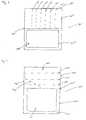
- Fig. 1A and fig. 1B illustrates a cover unit 101 comprising a patient adherent member 103 and a barrier member 105 connected along a connection line 107.
- the barrier member 105 comprises a covering layer 109 comprising a flap 111 next to the connection line.
- the barrier member 105 further comprises a film 125.
- the film 125 is a relative stiff material, which enables the barrier member 105 to be at a position upright to the patient adherent member 103 whereby the puncture site 121 is easily accessible.
- the barrier member 105 defines a puncture procedure area 114 and a scanning area 116.
- the patient adherent member 103 is attached to the wrist 117 of a patient.
- a cannula 119 is to be inserted through the skin into an anatomical structure such as a vein or an artery at the puncture site 121.
- An ultrasonic device 123 is arranged at the top of the patient adherent member 103.
- the patient adherent member 103 is attached directly to the skin 118 of the patient.
- the film 125 comprises glue 120 allowing an ultrasonic signal to be transmitted. No air is present between the film 125 and the skin 118 of the patient. Hence, visualisation of anatomical structures close to the puncture site 121 using ultrasound is possible.
- the puncturing procedure takes place as follows: The wrist 117 is washed and/or disinfected. Then the covering layer of the patient adherent layer 103 is removed and the patient adherent layer 103 attached to the skin of the patient.
- the barrier member 105 is arranged in an upright position allowing puncturing. Gel is placed on the film 125 and the ultrasonic device 123 starts scanning. The cannula 119 is inserted into an anatomical structure guided by the ultrasonic scanning.
- the ultrasonic device 123 is removed, and the film 125 wiped, the covering layer 109 of the barrier member 105 removed and the barrier member 105 attached to the skin for maintaining the cannula 119 in position.
- the covering layer 109 of the barrier member 105 is easily removed by seizing the flap 111 of the covering layer 109, which is easily accessible.
- the covering layer 109 of the barrier member 105 is transparent to form a transparent window for coordinating the cannula 119 and the ultrasonic device 123. After the procedure, the covering layer 109 of the barrier member 105 is removed and the barrier member 105 arranged around or on either side of the inserted cannula 119.
- Fig. 2 illustrates a second embodiment of a cover unit 201 comprising three material layers with an ultrasound transparent film 225 with a glue-provided surface 227, a covering layer 209 and a support layer 215. The proportion of the layers is enlarged for the purpose of illustration.
- a connection line 207 separates the cover unit 201 into a patient adherent member 203 and a barrier member 205.
- a slit 229 is provided in the film 225, where the slit 229 extends from next to the connection line 207 and to a side edge 231 of the barrier member 205.
- the slit 229 divides the film 225 of the barrier member 205 into two parts which is arranged around or on either side of the puncture device to maintain the position of the puncture device.
- Fig. 3 illustrates a third embodiment of a cover unit 301 comprising a patient adherent member 303 and a barrier member 305 connected along a connection line 307.
- the barrier member 305 is provided with six weakening lines 333.
- the weakening lines 333 are arranged substantially perpendicular to the connection line 307.
- the weakening lines 333 extend from next to the connection line 307 and to the side edge 331.
- the weakening lines 333 can be provided in either the film or the film and the covering layer. However, the weakening lines 333 must not be constructed in a way where perforations are formed through the entire barrier member 305 since the barrier effect preventing contamination of the puncture site with the gel would be destroyed.
- a cover unit 301 provided with six weakening lines 333 enables that the barrier member 305 to be arranged smoothly around and on either side of the puncture device. If the puncture device is inserted differently from what was expected when attaching the cover unit 301 to the skin of the patient, the puncture device is not right in front of the expected weakening line 333 or expected slit in the barrier member 305. Multiple weakening lines 333 enable the barrier member 305 to be torn in front of the actual position of the puncture device.
- the patient adherent member 303 is provided with a gel-removing layer 334 which is ultrasound transparent.
- the gel-removing layer 334 can be removed after scanning with the ultrasonic device and inserting the puncture device. Hereby, it is not needed to wipe the patient adherent member 303 to remove additional gel.
- Fig. 4 illustrates a fourth embodiment of a cover unit 401 comprising a patient adherent member 403 and a barrier member 405 connected along a connection line 407.
- the barrier member 405 is provided with one weakening line 433 and three crossing shortening lines 435.
- the weakening line 433 extends from next to the connection line 407 and to the side edge 431.
- the crossing shortening lines 435 are substantially parallel to the connection line 407 and extend from one side edge 431 of the barrier member 405 to the opposite side edge 437.
- the parallel shortening lines 435 can be torn to change the size of the barrier member 405.
- the patient adherent member 403 comprises a two-parted support layer comprising a patient supporting border part 439 and a patient adherent supporting part 441.
- the two parts 439, 441 can be removed separately from one another.
- the patient adherent supporting part 441 can be removed before ultrasonic scanning leaving the patient supporting border part 439 on the patient adherent member 403.
- the patient supporting border part 439 stabilises the ultrasound transparent film from detaching from the skin during the puncturing procedure.
- Fig. 5 illustrates a fifth embodiment of a cover unit 501 comprising a patient adherent member 503 and a barrier member 505 connected along a connection line 507.
- the width 543 of barrier member 505 is larger than the width 545 of the patient adherent member 503. This embodiment enhances the barrier effect by preventing gel from passing the side edges 531, 537 of the barrier member 501.
- the fifth embodiment further comprises a crossing shortening line 535 non-parallel to the connection line 507.
- This crossing shortening line 535 extends from one side edge 531 of the barrier member 505 to the opposite side edge 537.
- the crossing shortening line 535 can be torn to change the size of the barrier member 505.
- Fig. 6 illustrates a sixth embodiment of a cover unit 601 comprising a patient adherent member 603 and a barrier member 605 connected along a connection line 607.
- the barrier member 605 is provided with a V-shaped slot 647 in the film of the barrier member 605.
- the support layer 639 of the patient adherent member 603 is separated into two parts comprising a patient supporting border part 639 and a patient adherent supporting part 641.
- the two parts 639, 641 can be removed separately from one another.
- the patient adherent supporting part 641 can be removed before ultrasonic scanning leaving the patient supporting border part 639 on the patient adherent member 603.
- the patient supporting border part 639 stabilises the ultrasound transparent film from detaching from the skin during the puncturing procedure.
- the support layer 651 of the barrier member 605 is separated into two parts comprising a first barrier supporting part 653 and a second barrier supporting part 655.
- the first barrier supporting part 653 is a barrier supporting border part.
- the two parts 653, 655 can be removed separately from one another.
- the second barrier supporting part 655 can be removed before ultrasonic scanning leaving the first barrier supporting part 653 on the barrier member 605.
- the first barrier supporting part 653 stabilises the barrier member 605 during the puncturing procedure and later during the attaching of the barrier member 605 to the skin of the patient.
- the barrier member 605 further comprises a covering layer 609, which is covering the glue-provided surface of the film during the puncturing procedure to maintain the effect of the barrier.
- Fig. 7 illustrates a seventh embodiment of a cover unit 701 comprising a round patient adherent member 703 and a triangular barrier member 705 connected along a connection line 707.
- the width 743 of the barrier member 705 next to the connection line 707 is larger than the width 745 of the patient adherent member 703. This embodiment enhances the barrier effect by preventing gel from passing the side edges 731 of the barrier member 701.
- the barrier member 705 is provided with two U-shaped slits 729.
- the U-shaped slits 729 extend from next to the connection line 707 and to the side edges 731.
- Fig. 8 illustrates an eight embodiment of a cover unit 801 comprising a patient adherent member 803 and a barrier member 805 connected along a connection line 807.
- the barrier member 805 is provided with three slits 829.
- the slits 829 extend from next to the connection line 807 and to the side edges 831.
- the size of the barrier member 805 and the patient adherent member 803 is unequal, and the connection line 807 is provided close to the lower edge 857 of the cover unit 801.
- connection line 807 is provided with indentations 859.
- the barrier member 805 and the patient adherent member 803 can easily be separated.
- Fig. 9 illustrates a ninth embodiment of a cover unit 901 comprising two material layers with an ultrasound transparent film 925 with a glue-provided surface 927 and a covering layer 909. The proportion of the layers is enlarged for the purpose of illustration.
- a connection line 907 separates the cover unit 901 into a patient adherent member 903 and a barrier member 905.
- a slit 929 is provided in the film 925, where the slit 929 extends from next to the connection line 907 and to a side edge 931 of the barrier member 905.
- the slit 929 divides the film 925 of the barrier member 905 into two parts which is arranged around or on either side of the puncture device to maintain the position of the puncture device.
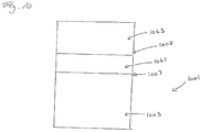
- Fig. 10 illustrates a tenth embodiment of a cover unit 1001 comprising a patient adherent member 1003 and a barrier member 1005 connected along a connection line 1007.
- the covering layer 1061,1063 of the barrier member 1005 consist of two parts arranged parallel to the connection line 1007 - a first covering part 1061 closest to the connection line 1007 and a second covering part 1063.
- the first covering part 1061 can be removed after the puncture procedure and the barrier member 1005 partly attached to the skin of the patient.
- the second covering part 1063 can be removed for example by cutting it off.
Landscapes
- Health & Medical Sciences (AREA)
- Life Sciences & Earth Sciences (AREA)
- Hematology (AREA)
- Animal Behavior & Ethology (AREA)
- Engineering & Computer Science (AREA)
- Anesthesiology (AREA)
- Biomedical Technology (AREA)
- Heart & Thoracic Surgery (AREA)
- Biophysics (AREA)
- Pulmonology (AREA)
- General Health & Medical Sciences (AREA)
- Public Health (AREA)
- Veterinary Medicine (AREA)
- Ultra Sonic Daignosis Equipment (AREA)
- Infusion, Injection, And Reservoir Apparatuses (AREA)
- Measurement Of The Respiration, Hearing Ability, Form, And Blood Characteristics Of Living Organisms (AREA)
- Media Introduction/Drainage Providing Device (AREA)
Claims (16)
- Unité de couvercle (101) destinée à être utilisée lors de l'introduction d'un dispositif de piqûre (119) tel qu'une canule dans une structure anatomique telle qu'une veine ou une artère et à maintenir ledit dispositif de piqûre (119) dans ladite structure anatomique, comprenant un film flexible (125) ayant une surface pourvue de colle (227) avec une colle pour une fixation sur la peau, et une couche de recouvrement amovible (109) pour recouvrir ladite surface pourvue de colle (227) et ladite unité de couvercle (101) comprenant un élément adhérant au patient (103) et un élément barrière (105) connectés le long d'une ligne de connexion (107) divisant ladite unité de couvercle en ledit élément adhérant au patient (103) et ledit élément barrière (105), ladite ligne de connexion (107), lors de l'utilisation, étant agencée à proximité d'un site de piqûre (121) chez un patient ;- ledit élément barrière (105) étant pourvu d'au moins une fente (229) ou d'une ligne d'affaiblissement (333) s'étendant à partir d'un bord latéral (331) de ladite unité de couvercle (101) vers ladite ligne de connexion (107) jusqu'à une position adjacente à ladite ligne de connexion (107) et étant fourni dans ledit film (125) ; et- en ce que ladite couche de recouvrement (109) dans l'élément barrière (105) peut être retirée du film (125) séparément de la couche de recouvrement (109) correspondante dans l'élément adhérant au patient (103)caractérisée en ce que- ledit film (125) est fait d'un matériau transparent aux ultrasons ;- ledit élément adhérant au patient (103) est transparent aux ultrasons au moins dans la zone adjacente à ladite ligne de connexion (107) ;- ladite colle permet à un signal ultrasonore d'être transmis.
- Unité de couvercle (101) selon la revendication 1 caractérisée en ce que ladite unité de couvercle (101) comprend en outre une couche de support (215), ladite couche de support (215) est collée sur ledit film (125) sur une surface opposée à ladite couche de recouvrement (109).
- Unité de couvercle (101) selon la revendication 2 caractérisée en ce que ladite couche de support (215) dans l'élément barrière (105) peut être retirée du film (125) séparément de la couche de support (215) correspondante dans l'élément adhérant au patient (103).
- Unité de couvercle (101) selon l'une quelconque des revendications précédentes caractérisée en ce que ledit élément adhérant au patient (103) comprend en outre une couche d'élimination de gel (334), ladite couche d'élimination de gel (334) étant transparente aux ultrasons.
- Unité de couvercle (101) selon l'une quelconque des revendications 2 à 4 caractérisée en ce que ladite couche de support (215) est séparée en une partie de bordure de support de patient (439) le long d'un ou de plusieurs bords dudit élément adhérant au patient (103) et au moins une partie de support adhérant au patient (441).
- Unité de couvercle (101) selon l'une quelconque des revendications 2 à 5 caractérisée en ce que ladite couche de support (215) est séparée en une première partie de support de barrière (653) dans ledit élément barrière (105) et au moins une deuxième partie de support de barrière (655).
- Unité de couvercle (101) selon l'une quelconque des revendications 2 à 6 caractérisée en ce qu'au moins une partie de ladite couche de support (215) est transparente aux ultrasons.
- Unité de couvercle (101) selon l'une quelconque des revendications précédentes caractérisée en ce que ladite couche de recouvrement (109) sur ledit élément barrière (105) est pourvue d'un rabat (111).
- Unité de couvercle (101) selon l'une quelconque des revendications précédentes caractérisée en ce que ladite au moins une fente (229) ou ligne d'affaiblissement (333) fournit une découpe en forme de U ou de V.
- Unité de couvercle (101) selon l'une quelconque des revendications précédentes caractérisée en ce que ladite au moins une ligne d'affaiblissement (333) comprend une ou plusieurs indentations ou perforations.
- Unité de couvercle (101) selon l'une quelconque des revendications précédentes caractérisée en ce qu'au moins une ligne de raccourcissement (435) s'étend à travers ledit élément barrière (105), de préférence de manière sensiblement parallèle à ladite ligne de connexion (107).
- Unité de couvercle (101) selon l'une quelconque des revendications précédentes caractérisée en ce que ladite couche de recouvrement (109) dudit élément barrière (105) comprend au moins deux parties (1061, 1063) pouvant être retirées séparément.
- Unité de couvercle (101) selon l'une quelconque des revendications précédentes caractérisée en ce qu'au moins une partie dudit élément barrière (105) est transparente, de préférence ladite partie dudit élément barrière (105) à côté de ladite ligne de connexion (107).
- Unité de couvercle (101) selon l'une quelconque des revendications précédentes caractérisée en ce que le long de ladite ligne de connexion (107), la largeur (546) dudit élément barrière (105) est supérieure à la largeur (545) dudit élément adhérant au patient (103).
- Unité de couvercle (101) selon l'une quelconque des revendications précédentes caractérisée en ce qu'une ou plusieurs indentations sont fournies dans ladite ligne de connexion (107).
- Unité de couvercle (101) selon l'une quelconque des revendications précédentes, caractérisée en ce qu'au moins deux types de colle sont fournis sur ladite surface pourvue de colle (227).
Priority Applications (2)
| Application Number | Priority Date | Filing Date | Title |
|---|---|---|---|
| PL11850251T PL2654860T3 (pl) | 2010-12-23 | 2011-12-20 | Zespół osłonowy do stosowania przy wprowadzaniu urządzenia do wkłuć do struktury anatomicznej, takiej jak żyła lub tętnica i utrzymywania urządzenia do wkłuć w strukturze anatomicznej |
| EP11850251.7A EP2654860B8 (fr) | 2010-12-23 | 2011-12-20 | Unité de couvercle destinée à être utilisée lors de l'introduction d'un dispositif de piqûre dans une structure anatomique telle qu'une veine ou une artère et à maintenir ledit dispositif de piqûre dans la structure anatomique |
Applications Claiming Priority (4)
| Application Number | Priority Date | Filing Date | Title |
|---|---|---|---|
| US201061426531P | 2010-12-23 | 2010-12-23 | |
| EP10196787A EP2468228A1 (fr) | 2010-12-23 | 2010-12-23 | Unité de couverture pour une utilisation lors de l'insertion d'un dispositif de perforation dans une structure anatomique telle une veine ou une artère et pour maintenir ledit dispositif de perforation dans la structure anatomique |
| PCT/DK2011/050504 WO2012083965A1 (fr) | 2010-12-23 | 2011-12-20 | Unité de couvercle destinée à être utilisée lors de l'introduction d'un dispositif de piqûre dans une structure anatomique telle qu'une veine ou une artère et à maintenir ledit dispositif de piqûre dans la structure anatomique |
| EP11850251.7A EP2654860B8 (fr) | 2010-12-23 | 2011-12-20 | Unité de couvercle destinée à être utilisée lors de l'introduction d'un dispositif de piqûre dans une structure anatomique telle qu'une veine ou une artère et à maintenir ledit dispositif de piqûre dans la structure anatomique |
Publications (4)
| Publication Number | Publication Date |
|---|---|
| EP2654860A1 EP2654860A1 (fr) | 2013-10-30 |
| EP2654860A4 EP2654860A4 (fr) | 2017-02-08 |
| EP2654860B1 true EP2654860B1 (fr) | 2019-12-04 |
| EP2654860B8 EP2654860B8 (fr) | 2020-01-15 |
Family
ID=43984139
Family Applications (2)
| Application Number | Title | Priority Date | Filing Date |
|---|---|---|---|
| EP10196787A Withdrawn EP2468228A1 (fr) | 2010-12-23 | 2010-12-23 | Unité de couverture pour une utilisation lors de l'insertion d'un dispositif de perforation dans une structure anatomique telle une veine ou une artère et pour maintenir ledit dispositif de perforation dans la structure anatomique |
| EP11850251.7A Active EP2654860B8 (fr) | 2010-12-23 | 2011-12-20 | Unité de couvercle destinée à être utilisée lors de l'introduction d'un dispositif de piqûre dans une structure anatomique telle qu'une veine ou une artère et à maintenir ledit dispositif de piqûre dans la structure anatomique |
Family Applications Before (1)
| Application Number | Title | Priority Date | Filing Date |
|---|---|---|---|
| EP10196787A Withdrawn EP2468228A1 (fr) | 2010-12-23 | 2010-12-23 | Unité de couverture pour une utilisation lors de l'insertion d'un dispositif de perforation dans une structure anatomique telle une veine ou une artère et pour maintenir ledit dispositif de perforation dans la structure anatomique |
Country Status (10)
| Country | Link |
|---|---|
| US (1) | US9393381B2 (fr) |
| EP (2) | EP2468228A1 (fr) |
| JP (1) | JP6176850B2 (fr) |
| CN (1) | CN103370094B (fr) |
| AU (1) | AU2011348589B2 (fr) |
| BR (1) | BR112013015843B1 (fr) |
| CA (1) | CA2822670C (fr) |
| ES (1) | ES2774743T3 (fr) |
| PL (1) | PL2654860T3 (fr) |
| WO (1) | WO2012083965A1 (fr) |
Families Citing this family (6)
| Publication number | Priority date | Publication date | Assignee | Title |
|---|---|---|---|---|
| EP2910224A1 (fr) * | 2014-02-19 | 2015-08-26 | Swiss VX Venentherapie und Forschung GmbH | Bandage de film adhésif de compression médicale |
| ES2921990T3 (es) | 2014-09-10 | 2022-09-05 | Bard Inc C R | Apósito protector para un dispositivo médico colocado en la piel |
| WO2019145009A1 (fr) * | 2018-01-25 | 2019-08-01 | Us Enovacor Aps | Procédé de préparation d'un site d'insertion de canule sur la peau d'un patient, unité de couverture de peau à cet effet et utilisation associée |
| DK201870085A1 (en) * | 2018-02-12 | 2019-09-09 | Us Enovacor Aps | A method for preparing an insertion site for a cannula on a skin of a patient, a skin cover unit therefore and its use |
| WO2023127821A1 (fr) | 2021-12-28 | 2023-07-06 | ニチバン株式会社 | Matériau de pansement pour ponction |
| KR20260048539A (ko) | 2023-06-14 | 2026-04-10 | 파커 래버러토리즈, 아이엔씨. | 피부 커버 유닛를 사용하여 대상자의 피부에 천공 장치를 삽입하기 위한 방법 |
Citations (2)
| Publication number | Priority date | Publication date | Assignee | Title |
|---|---|---|---|---|
| US20060036203A1 (en) * | 2002-06-19 | 2006-02-16 | Amina Ouchene | Device for applying controlled and adjustable compression to a limb |
| US20060241522A1 (en) * | 2003-06-18 | 2006-10-26 | Chandraratna Premindra A | Ultrasound devices and methods for treating ischemia and other cardiovascular disorders |
Family Cites Families (13)
| Publication number | Priority date | Publication date | Assignee | Title |
|---|---|---|---|---|
| US1532900A (en) * | 1921-11-07 | 1925-04-07 | William F Zent | Adhesive binding strip for closing and reclosing packages |
| SE419163B (sv) * | 1978-09-11 | 1981-07-20 | Harry Karlsson | Plaster avsett att fasthalla en kanyl |
| US4706662A (en) * | 1981-12-11 | 1987-11-17 | Johnson & Johnson Products, Inc. | Film dressing with fabric backing |
| AU563489B2 (en) * | 1982-10-20 | 1987-07-09 | Smith & Nephew Associated Companies Plc | Bacteria proof adhesive dressing |
| GB2128479A (en) * | 1982-10-20 | 1984-05-02 | Smith & Nephew Ass | Application of surgical dressings |
| DK193991D0 (da) * | 1991-11-29 | 1991-11-29 | Nicomed Aps | A bandage for fixating a cannula of a venous catheter relative to a skin surface part of a person |
| US6861570B1 (en) * | 1997-09-22 | 2005-03-01 | A. Bart Flick | Multilayer conductive appliance having wound healing and analgesic properties |
| US6612990B1 (en) * | 1999-04-08 | 2003-09-02 | Rick L. Pruter | Method and apparatus for guiding needles |
| US7122712B2 (en) * | 2002-12-02 | 2006-10-17 | Lutri Thomas P | Surgical bandage and methods for treating open wounds |
| US7588541B2 (en) * | 2003-12-10 | 2009-09-15 | Sonosite, Inc. | Method and system for positioning a medical device at one or more angles relative to an imaging probe |
| JP2007167424A (ja) * | 2005-12-22 | 2007-07-05 | Nagasaki Univ | フィルム状エコーゲル |
| US8231533B2 (en) * | 2007-02-16 | 2012-07-31 | Buchalter Neal | Ultrasound coupling device |
| CA2711174A1 (fr) * | 2007-12-31 | 2009-07-16 | Acclarent, Inc. | Pansement de tissu mucosal et son procede d'utilisation |
-
2010
- 2010-12-23 EP EP10196787A patent/EP2468228A1/fr not_active Withdrawn
-
2011
- 2011-12-20 CN CN201180062317.2A patent/CN103370094B/zh active Active
- 2011-12-20 US US13/996,788 patent/US9393381B2/en active Active
- 2011-12-20 AU AU2011348589A patent/AU2011348589B2/en active Active
- 2011-12-20 JP JP2013545053A patent/JP6176850B2/ja active Active
- 2011-12-20 CA CA2822670A patent/CA2822670C/fr active Active
- 2011-12-20 BR BR112013015843-3A patent/BR112013015843B1/pt active IP Right Grant
- 2011-12-20 PL PL11850251T patent/PL2654860T3/pl unknown
- 2011-12-20 ES ES11850251T patent/ES2774743T3/es active Active
- 2011-12-20 WO PCT/DK2011/050504 patent/WO2012083965A1/fr not_active Ceased
- 2011-12-20 EP EP11850251.7A patent/EP2654860B8/fr active Active
Patent Citations (2)
| Publication number | Priority date | Publication date | Assignee | Title |
|---|---|---|---|---|
| US20060036203A1 (en) * | 2002-06-19 | 2006-02-16 | Amina Ouchene | Device for applying controlled and adjustable compression to a limb |
| US20060241522A1 (en) * | 2003-06-18 | 2006-10-26 | Chandraratna Premindra A | Ultrasound devices and methods for treating ischemia and other cardiovascular disorders |
Also Published As
| Publication number | Publication date |
|---|---|
| AU2011348589B2 (en) | 2016-07-07 |
| US9393381B2 (en) | 2016-07-19 |
| BR112013015843B1 (pt) | 2020-12-29 |
| JP6176850B2 (ja) | 2017-08-09 |
| CN103370094B (zh) | 2015-12-16 |
| AU2011348589A1 (en) | 2013-07-11 |
| CN103370094A (zh) | 2013-10-23 |
| BR112013015843A2 (pt) | 2018-12-11 |
| US20130289404A1 (en) | 2013-10-31 |
| JP2014507181A (ja) | 2014-03-27 |
| EP2654860A1 (fr) | 2013-10-30 |
| AU2011348589A8 (en) | 2013-09-05 |
| EP2654860B8 (fr) | 2020-01-15 |
| EP2468228A1 (fr) | 2012-06-27 |
| WO2012083965A1 (fr) | 2012-06-28 |
| CA2822670A1 (fr) | 2012-06-28 |
| CA2822670C (fr) | 2019-05-07 |
| EP2654860A4 (fr) | 2017-02-08 |
| ES2774743T3 (es) | 2020-07-22 |
| PL2654860T3 (pl) | 2020-11-02 |
Similar Documents
| Publication | Publication Date | Title |
|---|---|---|
| EP2654860B1 (fr) | Unité de couvercle destinée à être utilisée lors de l'introduction d'un dispositif de piqûre dans une structure anatomique telle qu'une veine ou une artère et à maintenir ledit dispositif de piqûre dans la structure anatomique | |
| US10271916B2 (en) | Zip strip draping system and methods of manufacturing same | |
| US10039610B2 (en) | Zip strip draping system and methods of manufacturing same | |
| EP0247571B1 (fr) | Système pour fixer des cathéters, canules ou analogues contre la peau | |
| US8663266B1 (en) | Device and method to protect needle localization wire | |
| US20230380862A1 (en) | Window dressing for use with ultrasonic aid in venipuncture | |
| EP2793730A1 (fr) | Système d'orientation anatomique | |
| JP2022529125A (ja) | 使い捨て手術用ドレープ | |
| CA2864281A1 (fr) | Pansement canule en deux parties | |
| EP3270816B1 (fr) | Champ opératoire pour l'enregistrement d'un patient et un procédé d'enregistrement utilisant un tel champ opératoire | |
| US10492759B2 (en) | Ultrasound barrier devices and methods related thereto | |
| US10758671B2 (en) | Securement device assembly and securement and dressing device assembly and method of applying said device assemblies | |
| EP3181104B1 (fr) | Pansement de fixation de cathéter | |
| WO2023127821A1 (fr) | Matériau de pansement pour ponction | |
| AU2012312845A1 (en) | Zip strip draping system and methods of manufacturing same | |
| JP3198441U (ja) | チューブ固定用シート | |
| KR20260048539A (ko) | 피부 커버 유닛를 사용하여 대상자의 피부에 천공 장치를 삽입하기 위한 방법 | |
| ATE387900T1 (de) | Selbstschliessendes antiseptisches pflaster | |
| EP1859832A2 (fr) | Dispositif de fixation de canules et analogues a une partie du corps humain |
Legal Events
| Date | Code | Title | Description |
|---|---|---|---|
| PUAI | Public reference made under article 153(3) epc to a published international application that has entered the european phase |
Free format text: ORIGINAL CODE: 0009012 |
|
| 17P | Request for examination filed |
Effective date: 20130619 |
|
| AK | Designated contracting states |
Kind code of ref document: A1 Designated state(s): AL AT BE BG CH CY CZ DE DK EE ES FI FR GB GR HR HU IE IS IT LI LT LU LV MC MK MT NL NO PL PT RO RS SE SI SK SM TR |
|
| AX | Request for extension of the european patent |
Extension state: BA ME |
|
| REG | Reference to a national code |
Ref country code: DE Ref legal event code: R079 Ref document number: 602011063856 Country of ref document: DE Free format text: PREVIOUS MAIN CLASS: A61M0005420000 Ipc: A61F0013020000 |
|
| RA4 | Supplementary search report drawn up and despatched (corrected) |
Effective date: 20170109 |
|
| RIC1 | Information provided on ipc code assigned before grant |
Ipc: A61F 13/02 20060101AFI20170102BHEP Ipc: A61B 8/08 20060101ALI20170102BHEP Ipc: A61M 25/01 20060101ALI20170102BHEP Ipc: A61M 25/02 20060101ALI20170102BHEP |
|
| STAA | Information on the status of an ep patent application or granted ep patent |
Free format text: STATUS: EXAMINATION IS IN PROGRESS |
|
| 17Q | First examination report despatched |
Effective date: 20181214 |
|
| GRAP | Despatch of communication of intention to grant a patent |
Free format text: ORIGINAL CODE: EPIDOSNIGR1 |
|
| STAA | Information on the status of an ep patent application or granted ep patent |
Free format text: STATUS: GRANT OF PATENT IS INTENDED |
|
| INTG | Intention to grant announced |
Effective date: 20190701 |
|
| GRAS | Grant fee paid |
Free format text: ORIGINAL CODE: EPIDOSNIGR3 |
|
| GRAA | (expected) grant |
Free format text: ORIGINAL CODE: 0009210 |
|
| STAA | Information on the status of an ep patent application or granted ep patent |
Free format text: STATUS: THE PATENT HAS BEEN GRANTED |
|
| AK | Designated contracting states |
Kind code of ref document: B1 Designated state(s): AL AT BE BG CH CY CZ DE DK EE ES FI FR GB GR HR HU IE IS IT LI LT LU LV MC MK MT NL NO PL PT RO RS SE SI SK SM TR |
|
| AX | Request for extension of the european patent |
Extension state: BA ME |
|
| REG | Reference to a national code |
Ref country code: GB Ref legal event code: FG4D |
|
| REG | Reference to a national code |
Ref country code: CH Ref legal event code: EP |
|
| REG | Reference to a national code |
Ref country code: AT Ref legal event code: REF Ref document number: 1208477 Country of ref document: AT Kind code of ref document: T Effective date: 20191215 |
|
| REG | Reference to a national code |
Ref country code: DE Ref legal event code: R096 Ref document number: 602011063856 Country of ref document: DE |
|
| RAP2 | Party data changed (patent owner data changed or rights of a patent transferred) |
Owner name: US ENOVACOR APS |
|
| REG | Reference to a national code |
Ref country code: IE Ref legal event code: FG4D |
|
| REG | Reference to a national code |
Ref country code: CH Ref legal event code: PK Free format text: BERICHTIGUNG B8 |
|
| REG | Reference to a national code |
Ref country code: NL Ref legal event code: MP Effective date: 20191204 |
|
| REG | Reference to a national code |
Ref country code: LT Ref legal event code: MG4D |
|
| PG25 | Lapsed in a contracting state [announced via postgrant information from national office to epo] |
Ref country code: BG Free format text: LAPSE BECAUSE OF FAILURE TO SUBMIT A TRANSLATION OF THE DESCRIPTION OR TO PAY THE FEE WITHIN THE PRESCRIBED TIME-LIMIT Effective date: 20200304 Ref country code: FI Free format text: LAPSE BECAUSE OF FAILURE TO SUBMIT A TRANSLATION OF THE DESCRIPTION OR TO PAY THE FEE WITHIN THE PRESCRIBED TIME-LIMIT Effective date: 20191204 Ref country code: SE Free format text: LAPSE BECAUSE OF FAILURE TO SUBMIT A TRANSLATION OF THE DESCRIPTION OR TO PAY THE FEE WITHIN THE PRESCRIBED TIME-LIMIT Effective date: 20191204 Ref country code: LV Free format text: LAPSE BECAUSE OF FAILURE TO SUBMIT A TRANSLATION OF THE DESCRIPTION OR TO PAY THE FEE WITHIN THE PRESCRIBED TIME-LIMIT Effective date: 20191204 Ref country code: GR Free format text: LAPSE BECAUSE OF FAILURE TO SUBMIT A TRANSLATION OF THE DESCRIPTION OR TO PAY THE FEE WITHIN THE PRESCRIBED TIME-LIMIT Effective date: 20200305 Ref country code: NO Free format text: LAPSE BECAUSE OF FAILURE TO SUBMIT A TRANSLATION OF THE DESCRIPTION OR TO PAY THE FEE WITHIN THE PRESCRIBED TIME-LIMIT Effective date: 20200304 Ref country code: LT Free format text: LAPSE BECAUSE OF FAILURE TO SUBMIT A TRANSLATION OF THE DESCRIPTION OR TO PAY THE FEE WITHIN THE PRESCRIBED TIME-LIMIT Effective date: 20191204 |
|
| PG25 | Lapsed in a contracting state [announced via postgrant information from national office to epo] |
Ref country code: HR Free format text: LAPSE BECAUSE OF FAILURE TO SUBMIT A TRANSLATION OF THE DESCRIPTION OR TO PAY THE FEE WITHIN THE PRESCRIBED TIME-LIMIT Effective date: 20191204 Ref country code: RS Free format text: LAPSE BECAUSE OF FAILURE TO SUBMIT A TRANSLATION OF THE DESCRIPTION OR TO PAY THE FEE WITHIN THE PRESCRIBED TIME-LIMIT Effective date: 20191204 |
|
| PG25 | Lapsed in a contracting state [announced via postgrant information from national office to epo] |
Ref country code: AL Free format text: LAPSE BECAUSE OF FAILURE TO SUBMIT A TRANSLATION OF THE DESCRIPTION OR TO PAY THE FEE WITHIN THE PRESCRIBED TIME-LIMIT Effective date: 20191204 |
|
| REG | Reference to a national code |
Ref country code: ES Ref legal event code: FG2A Ref document number: 2774743 Country of ref document: ES Kind code of ref document: T3 Effective date: 20200722 |
|
| PG25 | Lapsed in a contracting state [announced via postgrant information from national office to epo] |
Ref country code: EE Free format text: LAPSE BECAUSE OF FAILURE TO SUBMIT A TRANSLATION OF THE DESCRIPTION OR TO PAY THE FEE WITHIN THE PRESCRIBED TIME-LIMIT Effective date: 20191204 Ref country code: RO Free format text: LAPSE BECAUSE OF FAILURE TO SUBMIT A TRANSLATION OF THE DESCRIPTION OR TO PAY THE FEE WITHIN THE PRESCRIBED TIME-LIMIT Effective date: 20191204 Ref country code: NL Free format text: LAPSE BECAUSE OF FAILURE TO SUBMIT A TRANSLATION OF THE DESCRIPTION OR TO PAY THE FEE WITHIN THE PRESCRIBED TIME-LIMIT Effective date: 20191204 Ref country code: CZ Free format text: LAPSE BECAUSE OF FAILURE TO SUBMIT A TRANSLATION OF THE DESCRIPTION OR TO PAY THE FEE WITHIN THE PRESCRIBED TIME-LIMIT Effective date: 20191204 Ref country code: PT Free format text: LAPSE BECAUSE OF FAILURE TO SUBMIT A TRANSLATION OF THE DESCRIPTION OR TO PAY THE FEE WITHIN THE PRESCRIBED TIME-LIMIT Effective date: 20200429 |
|
| REG | Reference to a national code |
Ref country code: CH Ref legal event code: PL |
|
| REG | Reference to a national code |
Ref country code: BE Ref legal event code: MM Effective date: 20191231 |
|
| PG25 | Lapsed in a contracting state [announced via postgrant information from national office to epo] |
Ref country code: IS Free format text: LAPSE BECAUSE OF FAILURE TO SUBMIT A TRANSLATION OF THE DESCRIPTION OR TO PAY THE FEE WITHIN THE PRESCRIBED TIME-LIMIT Effective date: 20200404 Ref country code: SK Free format text: LAPSE BECAUSE OF FAILURE TO SUBMIT A TRANSLATION OF THE DESCRIPTION OR TO PAY THE FEE WITHIN THE PRESCRIBED TIME-LIMIT Effective date: 20191204 Ref country code: SM Free format text: LAPSE BECAUSE OF FAILURE TO SUBMIT A TRANSLATION OF THE DESCRIPTION OR TO PAY THE FEE WITHIN THE PRESCRIBED TIME-LIMIT Effective date: 20191204 |
|
| REG | Reference to a national code |
Ref country code: DE Ref legal event code: R097 Ref document number: 602011063856 Country of ref document: DE |
|
| REG | Reference to a national code |
Ref country code: AT Ref legal event code: MK05 Ref document number: 1208477 Country of ref document: AT Kind code of ref document: T Effective date: 20191204 |
|
| PG25 | Lapsed in a contracting state [announced via postgrant information from national office to epo] |
Ref country code: MC Free format text: LAPSE BECAUSE OF FAILURE TO SUBMIT A TRANSLATION OF THE DESCRIPTION OR TO PAY THE FEE WITHIN THE PRESCRIBED TIME-LIMIT Effective date: 20191204 |
|
| PLBE | No opposition filed within time limit |
Free format text: ORIGINAL CODE: 0009261 |
|
| STAA | Information on the status of an ep patent application or granted ep patent |
Free format text: STATUS: NO OPPOSITION FILED WITHIN TIME LIMIT |
|
| PG25 | Lapsed in a contracting state [announced via postgrant information from national office to epo] |
Ref country code: LU Free format text: LAPSE BECAUSE OF NON-PAYMENT OF DUE FEES Effective date: 20191220 Ref country code: IE Free format text: LAPSE BECAUSE OF NON-PAYMENT OF DUE FEES Effective date: 20191220 Ref country code: DK Free format text: LAPSE BECAUSE OF FAILURE TO SUBMIT A TRANSLATION OF THE DESCRIPTION OR TO PAY THE FEE WITHIN THE PRESCRIBED TIME-LIMIT Effective date: 20191204 |
|
| 26N | No opposition filed |
Effective date: 20200907 |
|
| PG25 | Lapsed in a contracting state [announced via postgrant information from national office to epo] |
Ref country code: AT Free format text: LAPSE BECAUSE OF FAILURE TO SUBMIT A TRANSLATION OF THE DESCRIPTION OR TO PAY THE FEE WITHIN THE PRESCRIBED TIME-LIMIT Effective date: 20191204 Ref country code: CH Free format text: LAPSE BECAUSE OF NON-PAYMENT OF DUE FEES Effective date: 20191231 Ref country code: BE Free format text: LAPSE BECAUSE OF NON-PAYMENT OF DUE FEES Effective date: 20191231 Ref country code: SI Free format text: LAPSE BECAUSE OF FAILURE TO SUBMIT A TRANSLATION OF THE DESCRIPTION OR TO PAY THE FEE WITHIN THE PRESCRIBED TIME-LIMIT Effective date: 20191204 Ref country code: LI Free format text: LAPSE BECAUSE OF NON-PAYMENT OF DUE FEES Effective date: 20191231 |
|
| PG25 | Lapsed in a contracting state [announced via postgrant information from national office to epo] |
Ref country code: CY Free format text: LAPSE BECAUSE OF FAILURE TO SUBMIT A TRANSLATION OF THE DESCRIPTION OR TO PAY THE FEE WITHIN THE PRESCRIBED TIME-LIMIT Effective date: 20191204 |
|
| PG25 | Lapsed in a contracting state [announced via postgrant information from national office to epo] |
Ref country code: MT Free format text: LAPSE BECAUSE OF FAILURE TO SUBMIT A TRANSLATION OF THE DESCRIPTION OR TO PAY THE FEE WITHIN THE PRESCRIBED TIME-LIMIT Effective date: 20191204 Ref country code: HU Free format text: LAPSE BECAUSE OF FAILURE TO SUBMIT A TRANSLATION OF THE DESCRIPTION OR TO PAY THE FEE WITHIN THE PRESCRIBED TIME-LIMIT; INVALID AB INITIO Effective date: 20111220 |
|
| PG25 | Lapsed in a contracting state [announced via postgrant information from national office to epo] |
Ref country code: TR Free format text: LAPSE BECAUSE OF FAILURE TO SUBMIT A TRANSLATION OF THE DESCRIPTION OR TO PAY THE FEE WITHIN THE PRESCRIBED TIME-LIMIT Effective date: 20191204 |
|
| PG25 | Lapsed in a contracting state [announced via postgrant information from national office to epo] |
Ref country code: MK Free format text: LAPSE BECAUSE OF FAILURE TO SUBMIT A TRANSLATION OF THE DESCRIPTION OR TO PAY THE FEE WITHIN THE PRESCRIBED TIME-LIMIT Effective date: 20191204 |
|
| P01 | Opt-out of the competence of the unified patent court (upc) registered |
Effective date: 20230525 |
|
| PGFP | Annual fee paid to national office [announced via postgrant information from national office to epo] |
Ref country code: GB Payment date: 20251229 Year of fee payment: 15 |
|
| PGFP | Annual fee paid to national office [announced via postgrant information from national office to epo] |
Ref country code: IT Payment date: 20251219 Year of fee payment: 15 |
|
| PGFP | Annual fee paid to national office [announced via postgrant information from national office to epo] |
Ref country code: FR Payment date: 20251226 Year of fee payment: 15 |
|
| PGFP | Annual fee paid to national office [announced via postgrant information from national office to epo] |
Ref country code: PL Payment date: 20251203 Year of fee payment: 15 |
|
| PGFP | Annual fee paid to national office [announced via postgrant information from national office to epo] |
Ref country code: ES Payment date: 20260102 Year of fee payment: 15 |
|
| PGFP | Annual fee paid to national office [announced via postgrant information from national office to epo] |
Ref country code: DE Payment date: 20251229 Year of fee payment: 15 |