EP2655237B1 - Dispositif de ventilation d'un équipement élévateur - Google Patents
Dispositif de ventilation d'un équipement élévateur Download PDFInfo
- Publication number
- EP2655237B1 EP2655237B1 EP11791306.1A EP11791306A EP2655237B1 EP 2655237 B1 EP2655237 B1 EP 2655237B1 EP 11791306 A EP11791306 A EP 11791306A EP 2655237 B1 EP2655237 B1 EP 2655237B1
- Authority
- EP
- European Patent Office
- Prior art keywords
- ventilation
- cage
- elevator
- ventilating
- channel
- Prior art date
- Legal status (The legal status is an assumption and is not a legal conclusion. Google has not performed a legal analysis and makes no representation as to the accuracy of the status listed.)
- Active
Links
Images


Classifications
-
- B—PERFORMING OPERATIONS; TRANSPORTING
- B66—HOISTING; LIFTING; HAULING
- B66B—ELEVATORS; ESCALATORS OR MOVING WALKWAYS
- B66B11/00—Main component parts of lifts in, or associated with, buildings or other structures
- B66B11/02—Cages, i.e. cars
- B66B11/0226—Constructional features, e.g. walls assembly, decorative panels, comfort equipment, thermal or sound insulation
- B66B11/024—Ventilation systems
Definitions
- Each lift car is equipped with a ventilation device in an upper area and a lower area in accordance with a regulation for lift systems EN 81-1:1998+A3:2009.
- the various embodiments described here relate to such a device for ventilation of lift cars in lift systems.
- Known exemplary elevator systems consist of an elevator car, a counterweight and a support means which connects the elevator car and the counterweight to one another via a drive.
- This drive moves the elevator car in an elevator shaft.
- An elevator car according to the invention has a ventilation system which is required for an air exchange in the elevator car. The dynamic pressure on this elevator car creates a vertical air flow in the elevator car.
- EP0418511 describes a device for the ventilation of elevator cabins, whereby a vertical air flow is created in an elevator cabin, generated by the airflow and dynamic pressure on the air-displacing elevator cabin.
- a ventilation channel in an upper area of the elevator cabin consists of primary air openings, chambers, air ducts and secondary air openings.
- the chambers and air ducts are formed by panels and wind deflectors. The wind deflectors calm the air flow.
- the wind deflectors and the panels are provided with a material for sound insulation.
- the object of the invention is therefore to provide a ventilation device which, through a simpler design of components, creates a ventilation channel while at the same time effectively insulating the noise in the cabin interior.
- an elevator car that is located in an elevator shaft is movable, wherein a ventilation device is attached to an outer surface of the cabin, wherein this ventilation device forms at least one ventilation duct, wherein the at least one ventilation duct has at least one primary ventilation opening which enables an exchange of air between the ventilation duct and the elevator shaft, wherein at least one of the outer surfaces of the cabin has at least one secondary ventilation opening which enables an exchange of air between a cabin interior and the at least one ventilation duct, with at least one element made of insulating material, wherein the at least one element essentially determines a course of the at least one ventilation duct.
- the invention is based on the finding that a simplified design of the ventilation device simplifies production and minimizes costs.
- a combination of shaping the ventilation duct with lining this ventilation duct with insulating material saves installation and production costs.
- At least one of the ventilation channels is straight-lined.
- the advantage is that it is easy to manufacture, as the ventilation channels can be easily inserted into the material of the element.
- the ventilation channels are created by drilling holes.
- the at least one ventilation channel is formed by a single element, with one or more essentially straight ventilation channels being formed by a recess in this element.
- At least one support is arranged in the at least one ventilation channel.
- the advantage of such a support is increased stability of the ventilation channel.
- a further development of the ventilation device not according to the invention consists of two elements, whereby both elements determine a course of at least one ventilation duct.
- the advantage is freedom of design of the ventilation ducts when installing the ventilation device. It is also advantageous to choose one of the two elements which increases the stability of the ventilation device.
- At least one element of the ventilation device has porous areas, whereby the air flows through these porous areas, whereby these porous areas at least partially form the at least one ventilation channel.
- At least one of the elements of the ventilation device is adhesively fixed to one of the outer surfaces of the cabin.
- one of the ventilation devices is arranged on the cabin roof and is part of a skirting board.
- a combination of the skirting board with the ventilation device saves installation effort and costs.
- ventilation ducts are arranged on one of the cabin outer surfaces, wherein at least one secondary ventilation opening is arranged in this cabin outer surface, wherein the at least one secondary ventilation opening enables an exchange of air between the ventilation ducts and the cabin interior, wherein the ventilation duct has a primary ventilation opening, wherein the at least one primary ventilation opening enables an exchange of air between the ventilation duct and the elevator shaft, wherein a fan is arranged on this primary ventilation opening such that an air flow through the ventilation duct can essentially only be generated by the operation of the fan, wherein an exchange of air between the at least one ventilation duct and the ventilation duct can only take place through the cabin interior and/or the elevator shaft.
- the fan can be switched on.
- the advantage is that the fan only needs to be operated when required. This is possible, for example, after a long period of downtime.
- the fan is a computer fan.
- the advantage is that a generally known computer fan causes minimal costs both in terms of procurement and operation.
- the cabin walls 14 are raised above a level of the cabin roof 12 in the form of a balustrade 26.
- Part of this balustrade 26 is a skirting board 28 on the cabin roof 12.
- a ventilation system consists of an upper ventilation device 18 and a lower ventilation device 20.
- the upper ventilation device 18 is designed as a Part of the baseboard 28 is arranged on the cabin roof 12.
- the lower ventilation device 20 is arranged on the cabin floor 10.
- the upper ventilation device 18 is arranged on the car roof 12 in such a way that air is exchanged between the ventilation duct 42 and the car interior 16 through the secondary ventilation opening 38. Air is exchanged between the elevator shaft 4 and the ventilation duct 42 through the primary ventilation openings 36.
- the car roof 12 and the element 30 are shaped at their common contact surface in such a way that the air flow through the ventilation duct 42 and the secondary ventilation opening 38 does not cause unnecessary noise.
- the element 30 can consist of any insulating material in order to minimize noise that occurs, for example caused by air currents or elevator travel.
- the insulating material can be, for example, a porous solid body or a foam.
- the porous area 54 can, for example, take on the function of additional sound insulation or a filter to prevent contamination in the cabin interior 16. These contaminations include, for example, insects, dust, liquids, but also unpleasant odors.
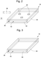
- FIG. 4 shows a further embodiment of the upper ventilation device 18.
- the upper ventilation device 18 consists of an element 30. Recesses 52 with primary ventilation openings 36 run through this element 30 in a straight line. These recesses 52 are created by drillings 56.
- the advantage of these ventilation channels 42 created by drilling is that they are inexpensive to manufacture. Alternatively, at least one of these ventilation channels 42 can have curves of any geometry in order to achieve increased noise insulation.
- the upper ventilation device 18 of the Figures 2, 3 , 4 also consist of several elements 301, 302, wherein one of these elements 302 is made of a material for sound insulation.
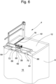
- Figure 5 shows a perspective sectional view of the upper ventilation device 18 on the cabin roof 12.
- the upper ventilation device 18 is provided with a bevel 24 as part of a baseboard 28. This bevel 24 raises a cabin wall 14 above a level of the upper ventilation device 18.
- a cable guide 48 is arranged on the bevel 24.
- the upper ventilation device 18 consists of several elements. These elements are a cover element 301 and an insulating body 302, which are adhesively attached to the cabin roof 12. Between the cover element 301 and the insulating body 302 there is a ventilation channel 42.
- the cover element 301 and the insulating body 302 essentially determine a course of the ventilation channel 42.
- the cover element 301 has primary ventilation openings 36. Secondary ventilation openings 38 are located in the cabin roof 12.
- the Figures 2 to 5 The properties of an upper ventilation device 18 described in more detail can also be transferred to a lower ventilation device 20 in the area of a cabin floor 10.
- the ventilation devices 18, 20 can be arranged on all cabin outer surfaces 10, 12, 14.
- the standard EN 81-1:1998+A3:2009 requires that a balustrade and a toeboard are present if, for example, a horizontal distance of 0.3 m from a car roof to a shaft wall is exceeded. A minimum height of this balustrade depends on this horizontal distance.
- the toeboard 28 has a required height of at least 0.1 m above a level of the car roof 12. It is possible to install the upper ventilation system 18 as part of this toeboard 28. Provided that the upper ventilation device 18 must not be walked on, the height of the upper ventilation device 18 above the level of the car roof 12 can be considered as part of the required Height of the baseboard 28 must be taken into account. In order to complete the required height of the baseboard 28, the upper ventilation device 18 is provided with the bevel 24. The height of the upper ventilation device 18 above the cabin roof 12 added to a vertical height of the bevel 24 corresponds to the required height of the baseboard 28.
- the ventilation ducts 58 can be made small and arranged on the cabin outer surfaces 10, 12, 14 to save space.
- the fan 60 can be a commercially available computer fan, for example.
- the ventilation ducts 58 and/or the ventilation devices 18, 20 can be designed in such a way that they are not connected to the cabin frame 68 in order to avoid structure-borne sound bridges.
Landscapes
- Engineering & Computer Science (AREA)
- Civil Engineering (AREA)
- Mechanical Engineering (AREA)
- Structural Engineering (AREA)
- Cage And Drive Apparatuses For Elevators (AREA)
- Building Environments (AREA)
- Ventilation (AREA)
Claims (14)
- Cabine d'ascenseur (8), laquelle est mobile dans une cage d'ascenseur (4),comportant un dispositif d'aération (18, 20) fixé au niveau d'une surface extérieure de cabine (10, 12, 14),lequel crée au moins un canal de ventilation (42),dans laquelle l'au moins un canal de ventilation (42) présente au moins une ouverture de ventilation primaire (36) qui permet un échange d'air entre le canal de ventilation (42) et la cage d'ascenseur (4),dans laquelle au moins l'une des surfaces extérieures de cabine (10, 12, 14) présente au moins une ouverture de ventilation secondaire (38) qui permet un échange d'air entre un espace intérieur de cabine (16) et l'au moins un canal de ventilation (42), comportant au moins un élément (30) en matériau isolant,dans laquelle l'au moins un élément (30) détermine sensiblement une trajectoire de l'au moins un canal de ventilation (42),caractérisée en ce queune mise en forme du canal de ventilation (42) et un revêtement du canal de ventilation (42) sont obtenus au moyen du matériau isolant.
- Cabine d'ascenseur (8) selon la revendication 1, caractérisée en ce qu'au moins l'un des canaux de ventilation (42) est formé de manière rectiligne.
- Cabine d'ascenseur (8) selon l'une des revendications précédentes, caractérisée en ce que
au moins l'un des canaux de ventilation (42) présente des courbures. - Cabine d'ascenseur (8) selon la revendication 1, caractérisée en ce que l'au moins un canal de ventilation (42) est formé par un seul élément (30), dans laquelle un ou plusieurs canaux de ventilation (42) sensiblement rectilignes sont créés par un évidement dans ledit élément (30).
- Cabine d'ascenseur (8) selon la revendication 4, caractérisée en ce que les canaux de ventilation (42) sont produits par des alésages.
- Cabine d'ascenseur (8) selon la revendication 5, caractérisée en ce que l'au moins un canal de ventilation (42) comprend au moins un support (50).
- Cabine d'ascenseur (8) selon l'une des revendications précédentes, caractérisée en ce queau moins un élément (301, 302) présente des zones poreuses (54),dans laquelle l'air circule à travers lesdites zones poreuses (54),dans laquelle lesdites zones poreuses (54) créent au moins partiellement l'au moins un canal de ventilation (42).
- Cabine d'ascenseur (8) selon l'une des revendications précédentes, caractérisée en ce que
au moins l'un des éléments (301, 302) est collé au niveau de l'une des surfaces extérieures de cabine (12). - Cabine d'ascenseur (8) selon l'une des revendications précédentes, caractérisée en ce que
l'un des dispositifs d'aération (18) est disposé sur le toit de cabine (12) et fait partie d'une plinthe (24). - Cabine d'ascenseur (8) selon l'une des revendications 1 à 8, caractérisée en ce que au moins l'un des dispositifs d'aération (18, 20) est disposé au niveau de la paroi de cabine (14).
- Cabine d'ascenseur (8) selon l'une des revendications précédentes, caractérisée en ce que
le dispositif d'aération (18, 20) présente un guide-câble (48). - Cabine d'ascenseur (8) selon l'une des revendications précédentes, caractérisée en ce quedes canaux d'aération (58) sont disposés au niveau de l'une des surfaces extérieures de cabine (10, 12, 14),dans laquelle au moins une ouverture d'aération secondaire (64) est disposée dans ladite surface extérieure de cabine (10, 12, 14),dans laquelle l'au moins une ouverture d'aération secondaire (64) permet un échange d'air entre les canaux d'aération (58) et l'espace intérieur de cabine (16),dans laquelle le canal d'aération (58) comprend une ouverture d'aération primaire (66), dans laquelle l'au moins une ouverture d'aération primaire (66) permet un échange d'air entre le canal d'aération (58) et la cage d'ascenseur (4),dans laquelle un ventilateur (60) est disposé au niveau de ladite ouverture d'aération primaire (66) de telle sorte qu'un flux d'air peut être produit à travers le canal d'aération (58) sensiblement uniquement par le fonctionnement du ventilateur (60),dans laquelle un échange d'air entre l'au moins un canal de ventilation (42) et le canal d'aération (58) ne peut avoir lieu qu'à travers l'espace intérieur de cabine (16) et/ou la cage d'ascenseur (4).
- Cabine d'ascenseur (8) selon la revendication 12, caractérisée en ce que le ventilateur (60) peut être activé.
- Cabine d'ascenseur (8) selon l'une des revendications 12 et 13,
caractérisée en ce que
le ventilateur (60) est un ventilateur d'ordinateur.
Priority Applications (1)
| Application Number | Priority Date | Filing Date | Title |
|---|---|---|---|
| EP11791306.1A EP2655237B1 (fr) | 2010-12-22 | 2011-12-07 | Dispositif de ventilation d'un équipement élévateur |
Applications Claiming Priority (3)
| Application Number | Priority Date | Filing Date | Title |
|---|---|---|---|
| EP10196612 | 2010-12-22 | ||
| EP11791306.1A EP2655237B1 (fr) | 2010-12-22 | 2011-12-07 | Dispositif de ventilation d'un équipement élévateur |
| PCT/EP2011/072088 WO2012084521A1 (fr) | 2010-12-22 | 2011-12-07 | Dispositif de ventilation d'un équipement élévateur |
Publications (3)
| Publication Number | Publication Date |
|---|---|
| EP2655237A1 EP2655237A1 (fr) | 2013-10-30 |
| EP2655237B1 true EP2655237B1 (fr) | 2024-07-03 |
| EP2655237C0 EP2655237C0 (fr) | 2024-07-03 |
Family
ID=44140954
Family Applications (1)
| Application Number | Title | Priority Date | Filing Date |
|---|---|---|---|
| EP11791306.1A Active EP2655237B1 (fr) | 2010-12-22 | 2011-12-07 | Dispositif de ventilation d'un équipement élévateur |
Country Status (6)
| Country | Link |
|---|---|
| US (1) | US9248996B2 (fr) |
| EP (1) | EP2655237B1 (fr) |
| CN (1) | CN103269968B (fr) |
| AU (1) | AU2011347865B2 (fr) |
| MY (1) | MY164699A (fr) |
| WO (1) | WO2012084521A1 (fr) |
Families Citing this family (11)
| Publication number | Priority date | Publication date | Assignee | Title |
|---|---|---|---|---|
| JP6280469B2 (ja) * | 2014-08-11 | 2018-02-14 | 株式会社日立製作所 | 乗りかご及びエレベータ装置 |
| ES2911757T3 (es) * | 2014-12-23 | 2022-05-20 | Otis Elevator Co | Sistema de ascensor con sistema de ventilación |
| CN105600651B (zh) * | 2015-11-25 | 2018-07-13 | 佛山住友富士电梯有限公司 | 一种电梯轿厢及一种电梯轿厢通风方法 |
| CN109963804B (zh) * | 2016-11-15 | 2021-10-12 | 因温特奥股份公司 | 电梯轿厢 |
| CN111362085B (zh) * | 2018-12-26 | 2022-12-20 | 奥的斯电梯公司 | 栏杆组件、轿厢和电梯 |
| US11279594B2 (en) * | 2019-11-14 | 2022-03-22 | Otis Elevator Company | Sound absorbing panels for elevator |
| WO2021121904A1 (fr) * | 2019-12-20 | 2021-06-24 | Inventio Ag | Balustrade pivotante de cabine d'ascenseur et procédé de maintenance pour ascenseur |
| CN111332911B (zh) * | 2020-03-25 | 2021-06-22 | 上海菱光电梯配件有限公司 | 一种具有较好通风性能的电梯轿厢 |
| CN112361548B (zh) * | 2020-10-22 | 2021-11-19 | 珠海格力电器股份有限公司 | 一种设备控制方法、装置及电梯 |
| WO2022122744A1 (fr) | 2020-12-07 | 2022-06-16 | Dussmann Technical Solutions Gmbh | Cabine d'ascenseur comprenant des moyens de ventilation pour ventiler la cabine lorsque la cabine est fermée pendant un trajet |
| DE102020132512A1 (de) | 2020-12-07 | 2022-06-09 | Dussmann Technical Solutions Gmbh | Aufzugskabine mit Belüftungsmitteln zum Belüften der Kabine bei geschlossener Kabine während der Fahrt |
Family Cites Families (16)
| Publication number | Priority date | Publication date | Assignee | Title |
|---|---|---|---|---|
| US2398627A (en) * | 1944-08-30 | 1946-04-16 | Tyler Co W S | Means for purifying air in elevator cars |
| US4287962A (en) * | 1977-11-14 | 1981-09-08 | Industrial Acoustics Company | Packless silencer |
| JPS6022040Y2 (ja) * | 1979-11-05 | 1985-07-01 | 三菱電機株式会社 | エレベ−タのかご室 |
| ATE94848T1 (de) | 1989-09-22 | 1993-10-15 | Inventio Ag | Vorrichtung fuer die belueftung von schnellaufenden aufzugskabinen. |
| HU212565B (en) * | 1991-12-04 | 1996-08-29 | Inventio Ag | Equipment for the ventilation of the passanger compartment of high speed elevator cabins |
| US5354233A (en) * | 1992-10-02 | 1994-10-11 | Man-D-Tec, Inc. | Emergency ventilation system for elevator cab |
| JP2896284B2 (ja) * | 1993-02-04 | 1999-05-31 | 株式会社東芝 | エレベータかご換気用ダクトのアクティブ騒音制御装置 |
| CN1192963C (zh) * | 2000-04-24 | 2005-03-16 | 三菱电机株式会社 | 电梯控制装置 |
| US20050161280A1 (en) * | 2002-12-26 | 2005-07-28 | Fujitsu Limited | Silencer and electronic equipment |
| ATE530717T1 (de) * | 2004-05-07 | 2011-11-15 | Silenceair Internat Pty Ltd | Lüftungsvorrichtung und rahmensystem |
| CN101014524A (zh) * | 2004-06-30 | 2007-08-08 | 奥蒂斯电梯公司 | 带有消散性通风通道的电梯轿厢轿顶 |
| US20060185931A1 (en) * | 2005-02-04 | 2006-08-24 | Kawar Maher S | Acoustic noise reduction apparatus for personal computers and electronics |
| US8336672B2 (en) * | 2006-01-18 | 2012-12-25 | Bard Manufacturing Company | Air treatment and sound reduction system |
| DE202006007836U1 (de) * | 2006-05-16 | 2007-07-05 | Greifzug Hebezeugbau Gmbh | Fahrkorb für Hebeeinrichtungen |
| KR20090014596A (ko) * | 2007-08-06 | 2009-02-11 | 삼성전자주식회사 | 공기정화장치와 이를 구비한 엘리베이터 및 그 공기정화제어방법 |
| WO2010026626A1 (fr) * | 2008-09-03 | 2010-03-11 | 三菱電機株式会社 | Dispositif de cabine d'ascenseur |
-
2011
- 2011-12-07 EP EP11791306.1A patent/EP2655237B1/fr active Active
- 2011-12-07 WO PCT/EP2011/072088 patent/WO2012084521A1/fr not_active Ceased
- 2011-12-07 MY MYPI2013002348A patent/MY164699A/en unknown
- 2011-12-07 CN CN201180062026.3A patent/CN103269968B/zh active Active
- 2011-12-07 AU AU2011347865A patent/AU2011347865B2/en active Active
- 2011-12-22 US US13/334,824 patent/US9248996B2/en active Active
Also Published As
| Publication number | Publication date |
|---|---|
| CN103269968A (zh) | 2013-08-28 |
| US9248996B2 (en) | 2016-02-02 |
| CN103269968B (zh) | 2016-08-10 |
| WO2012084521A1 (fr) | 2012-06-28 |
| US20120164928A1 (en) | 2012-06-28 |
| AU2011347865B2 (en) | 2017-03-09 |
| MY164699A (en) | 2018-01-30 |
| EP2655237C0 (fr) | 2024-07-03 |
| AU2011347865A1 (en) | 2013-06-13 |
| EP2655237A1 (fr) | 2013-10-30 |
Similar Documents
| Publication | Publication Date | Title |
|---|---|---|
| EP2655237A1 (fr) | Dispositif de ventilation d'un équipement élévateur | |
| DE102011051489C5 (de) | Gebläse-Luftansaugungsvorrichtung | |
| DE2606494A1 (de) | Wandkonstruktion | |
| EP0418511A1 (fr) | Appareil de conditionnement de l'air pour cabines d'ascenseurs à grande vitesse | |
| EP3564125B1 (fr) | Cabine de douche modulaire pour avions | |
| EP2118577A1 (fr) | Sortie d'air et procédé pour sa fabrication | |
| EP1950167A1 (fr) | Système d'aération pour une cabine d'ascenseur tout comme cabine d'ascenseur et installation d'ascenseur dotée d'un tel système d'aération | |
| EP0735329A2 (fr) | Ventilateur pour salles propres | |
| EP3362395B1 (fr) | Cabine d'ascenseur dans une cage d'ascenseur | |
| EP3002173B1 (fr) | Vehicule sur rail dote d'un conduit de climatiseur de toit | |
| EP4217660A1 (fr) | Dispositif d'installation comportant des modules d'équipements techniques énergétiques ou du bâtiment, et procédé pour retirer un module d'un dispositif d'installation de ce type | |
| EP3285017A1 (fr) | Panneau de plafond radiant chauffant et rafraîchissant comprenant au moins un ventilateur | |
| EP2708827B1 (fr) | Entrée ou sortie d'air et système de ventilation doté de celle-ci | |
| EP0089500A1 (fr) | Boîtier pour installation de chauffage ou de climatisation de véhicules à moteur | |
| EP4594234A1 (fr) | Dispositif pour porter un moteur d'entraînement d'un système d'ascenseur | |
| DE1922943A1 (de) | Lueftungsschachtanlage | |
| EP0609727B1 (fr) | Boîtier d'un ventilateur à placer dans une ouverture de passage | |
| EP0607116B1 (fr) | Pièce de bout pour climatiseurs pour locaux | |
| DE102015218953A1 (de) | Fahrzeug mit Entlüftung nach Unterflur | |
| WO2003022655A1 (fr) | Locomotive dotee de couloirs lateraux | |
| EP0829409A2 (fr) | Dispositif de ventilation d'un véhicule ferroviaire | |
| EP1434709A1 (fr) | Systeme de ventilation pour vehicules | |
| DE102008011012B4 (de) | Schaltschrank | |
| EP2800684B1 (fr) | Véhicule ferroviaire comprenant une gaine de climatisation dans la zone de toit et procédé de construction d'une zone de toit d'un véhicule ferroviaire | |
| DE19502343A1 (de) | Feuchtigkeitsabweisende Belüftungsvorrichtung für ein Gehäuse |
Legal Events
| Date | Code | Title | Description |
|---|---|---|---|
| PUAI | Public reference made under article 153(3) epc to a published international application that has entered the european phase |
Free format text: ORIGINAL CODE: 0009012 |
|
| 17P | Request for examination filed |
Effective date: 20130524 |
|
| AK | Designated contracting states |
Kind code of ref document: A1 Designated state(s): AL AT BE BG CH CY CZ DE DK EE ES FI FR GB GR HR HU IE IS IT LI LT LU LV MC MK MT NL NO PL PT RO RS SE SI SK SM TR |
|
| DAX | Request for extension of the european patent (deleted) | ||
| 17Q | First examination report despatched |
Effective date: 20140806 |
|
| STAA | Information on the status of an ep patent application or granted ep patent |
Free format text: STATUS: EXAMINATION IS IN PROGRESS |
|
| RAP3 | Party data changed (applicant data changed or rights of an application transferred) |
Owner name: INVENTIO AG |
|
| GRAP | Despatch of communication of intention to grant a patent |
Free format text: ORIGINAL CODE: EPIDOSNIGR1 |
|
| STAA | Information on the status of an ep patent application or granted ep patent |
Free format text: STATUS: GRANT OF PATENT IS INTENDED |
|
| INTG | Intention to grant announced |
Effective date: 20240216 |
|
| GRAS | Grant fee paid |
Free format text: ORIGINAL CODE: EPIDOSNIGR3 |
|
| GRAA | (expected) grant |
Free format text: ORIGINAL CODE: 0009210 |
|
| STAA | Information on the status of an ep patent application or granted ep patent |
Free format text: STATUS: THE PATENT HAS BEEN GRANTED |
|
| AK | Designated contracting states |
Kind code of ref document: B1 Designated state(s): AL AT BE BG CH CY CZ DE DK EE ES FI FR GB GR HR HU IE IS IT LI LT LU LV MC MK MT NL NO PL PT RO RS SE SI SK SM TR |
|
| REG | Reference to a national code |
Ref country code: CH Ref legal event code: EP |
|
| REG | Reference to a national code |
Ref country code: DE Ref legal event code: R096 Ref document number: 502011017474 Country of ref document: DE |
|
| U01 | Request for unitary effect filed |
Effective date: 20240715 |
|
| U07 | Unitary effect registered |
Designated state(s): AT BE BG DE DK EE FI FR IT LT LU LV MT NL PT SE SI Effective date: 20240726 |
|
| PG25 | Lapsed in a contracting state [announced via postgrant information from national office to epo] |
Ref country code: NO Free format text: LAPSE BECAUSE OF FAILURE TO SUBMIT A TRANSLATION OF THE DESCRIPTION OR TO PAY THE FEE WITHIN THE PRESCRIBED TIME-LIMIT Effective date: 20241003 |
|
| PG25 | Lapsed in a contracting state [announced via postgrant information from national office to epo] |
Ref country code: PL Free format text: LAPSE BECAUSE OF FAILURE TO SUBMIT A TRANSLATION OF THE DESCRIPTION OR TO PAY THE FEE WITHIN THE PRESCRIBED TIME-LIMIT Effective date: 20240703 Ref country code: GR Free format text: LAPSE BECAUSE OF FAILURE TO SUBMIT A TRANSLATION OF THE DESCRIPTION OR TO PAY THE FEE WITHIN THE PRESCRIBED TIME-LIMIT Effective date: 20241004 |
|
| PG25 | Lapsed in a contracting state [announced via postgrant information from national office to epo] |
Ref country code: IS Free format text: LAPSE BECAUSE OF FAILURE TO SUBMIT A TRANSLATION OF THE DESCRIPTION OR TO PAY THE FEE WITHIN THE PRESCRIBED TIME-LIMIT Effective date: 20241103 |
|
| PG25 | Lapsed in a contracting state [announced via postgrant information from national office to epo] |
Ref country code: HR Free format text: LAPSE BECAUSE OF FAILURE TO SUBMIT A TRANSLATION OF THE DESCRIPTION OR TO PAY THE FEE WITHIN THE PRESCRIBED TIME-LIMIT Effective date: 20240703 Ref country code: CZ Free format text: LAPSE BECAUSE OF FAILURE TO SUBMIT A TRANSLATION OF THE DESCRIPTION OR TO PAY THE FEE WITHIN THE PRESCRIBED TIME-LIMIT Effective date: 20240703 |
|
| PG25 | Lapsed in a contracting state [announced via postgrant information from national office to epo] |
Ref country code: ES Free format text: LAPSE BECAUSE OF FAILURE TO SUBMIT A TRANSLATION OF THE DESCRIPTION OR TO PAY THE FEE WITHIN THE PRESCRIBED TIME-LIMIT Effective date: 20240703 Ref country code: RS Free format text: LAPSE BECAUSE OF FAILURE TO SUBMIT A TRANSLATION OF THE DESCRIPTION OR TO PAY THE FEE WITHIN THE PRESCRIBED TIME-LIMIT Effective date: 20241003 |
|
| U20 | Renewal fee for the european patent with unitary effect paid |
Year of fee payment: 14 Effective date: 20241225 |
|
| PG25 | Lapsed in a contracting state [announced via postgrant information from national office to epo] |
Ref country code: RS Free format text: LAPSE BECAUSE OF FAILURE TO SUBMIT A TRANSLATION OF THE DESCRIPTION OR TO PAY THE FEE WITHIN THE PRESCRIBED TIME-LIMIT Effective date: 20241003 Ref country code: PL Free format text: LAPSE BECAUSE OF FAILURE TO SUBMIT A TRANSLATION OF THE DESCRIPTION OR TO PAY THE FEE WITHIN THE PRESCRIBED TIME-LIMIT Effective date: 20240703 Ref country code: NO Free format text: LAPSE BECAUSE OF FAILURE TO SUBMIT A TRANSLATION OF THE DESCRIPTION OR TO PAY THE FEE WITHIN THE PRESCRIBED TIME-LIMIT Effective date: 20241003 Ref country code: IS Free format text: LAPSE BECAUSE OF FAILURE TO SUBMIT A TRANSLATION OF THE DESCRIPTION OR TO PAY THE FEE WITHIN THE PRESCRIBED TIME-LIMIT Effective date: 20241103 Ref country code: HR Free format text: LAPSE BECAUSE OF FAILURE TO SUBMIT A TRANSLATION OF THE DESCRIPTION OR TO PAY THE FEE WITHIN THE PRESCRIBED TIME-LIMIT Effective date: 20240703 Ref country code: GR Free format text: LAPSE BECAUSE OF FAILURE TO SUBMIT A TRANSLATION OF THE DESCRIPTION OR TO PAY THE FEE WITHIN THE PRESCRIBED TIME-LIMIT Effective date: 20241004 Ref country code: ES Free format text: LAPSE BECAUSE OF FAILURE TO SUBMIT A TRANSLATION OF THE DESCRIPTION OR TO PAY THE FEE WITHIN THE PRESCRIBED TIME-LIMIT Effective date: 20240703 Ref country code: CZ Free format text: LAPSE BECAUSE OF FAILURE TO SUBMIT A TRANSLATION OF THE DESCRIPTION OR TO PAY THE FEE WITHIN THE PRESCRIBED TIME-LIMIT Effective date: 20240703 |
|
| PG25 | Lapsed in a contracting state [announced via postgrant information from national office to epo] |
Ref country code: SM Free format text: LAPSE BECAUSE OF FAILURE TO SUBMIT A TRANSLATION OF THE DESCRIPTION OR TO PAY THE FEE WITHIN THE PRESCRIBED TIME-LIMIT Effective date: 20240703 |
|
| PG25 | Lapsed in a contracting state [announced via postgrant information from national office to epo] |
Ref country code: SK Free format text: LAPSE BECAUSE OF FAILURE TO SUBMIT A TRANSLATION OF THE DESCRIPTION OR TO PAY THE FEE WITHIN THE PRESCRIBED TIME-LIMIT Effective date: 20240703 |
|
| PLBE | No opposition filed within time limit |
Free format text: ORIGINAL CODE: 0009261 |
|
| STAA | Information on the status of an ep patent application or granted ep patent |
Free format text: STATUS: NO OPPOSITION FILED WITHIN TIME LIMIT |
|
| 26N | No opposition filed |
Effective date: 20250404 |
|
| PG25 | Lapsed in a contracting state [announced via postgrant information from national office to epo] |
Ref country code: MC Free format text: LAPSE BECAUSE OF FAILURE TO SUBMIT A TRANSLATION OF THE DESCRIPTION OR TO PAY THE FEE WITHIN THE PRESCRIBED TIME-LIMIT Effective date: 20240703 |
|
| PG25 | Lapsed in a contracting state [announced via postgrant information from national office to epo] |
Ref country code: IE Free format text: LAPSE BECAUSE OF NON-PAYMENT OF DUE FEES Effective date: 20241207 |
|
| PG25 | Lapsed in a contracting state [announced via postgrant information from national office to epo] |
Ref country code: RO Free format text: LAPSE BECAUSE OF FAILURE TO SUBMIT A TRANSLATION OF THE DESCRIPTION OR TO PAY THE FEE WITHIN THE PRESCRIBED TIME-LIMIT Effective date: 20240703 |
|
| REG | Reference to a national code |
Ref country code: CH Ref legal event code: U11 Free format text: ST27 STATUS EVENT CODE: U-0-0-U10-U11 (AS PROVIDED BY THE NATIONAL OFFICE) Effective date: 20260101 |
|
| PGFP | Annual fee paid to national office [announced via postgrant information from national office to epo] |
Ref country code: GB Payment date: 20251223 Year of fee payment: 15 |
|
| U20 | Renewal fee for the european patent with unitary effect paid |
Year of fee payment: 15 Effective date: 20251223 |
|
| PG25 | Lapsed in a contracting state [announced via postgrant information from national office to epo] |
Ref country code: CY Free format text: LAPSE BECAUSE OF FAILURE TO SUBMIT A TRANSLATION OF THE DESCRIPTION OR TO PAY THE FEE WITHIN THE PRESCRIBED TIME-LIMIT; INVALID AB INITIO Effective date: 20111207 |
|
| PGFP | Annual fee paid to national office [announced via postgrant information from national office to epo] |
Ref country code: CH Payment date: 20260101 Year of fee payment: 15 |