EP2655859B1 - Réseau de bord pour un véhicule - Google Patents
Réseau de bord pour un véhicule Download PDFInfo
- Publication number
- EP2655859B1 EP2655859B1 EP11794169.0A EP11794169A EP2655859B1 EP 2655859 B1 EP2655859 B1 EP 2655859B1 EP 11794169 A EP11794169 A EP 11794169A EP 2655859 B1 EP2655859 B1 EP 2655859B1
- Authority
- EP
- European Patent Office
- Prior art keywords
- switch
- voltage
- energy store
- energy
- control
- Prior art date
- Legal status (The legal status is an assumption and is not a legal conclusion. Google has not performed a legal analysis and makes no representation as to the accuracy of the status listed.)
- Active
Links
Images


Classifications
-
- B—PERFORMING OPERATIONS; TRANSPORTING
- B60—VEHICLES IN GENERAL
- B60R—VEHICLES, VEHICLE FITTINGS, OR VEHICLE PARTS, NOT OTHERWISE PROVIDED FOR
- B60R16/00—Electric or fluid circuits specially adapted for vehicles and not otherwise provided for; Arrangement of elements of electric or fluid circuits specially adapted for vehicles and not otherwise provided for
- B60R16/02—Electric or fluid circuits specially adapted for vehicles and not otherwise provided for; Arrangement of elements of electric or fluid circuits specially adapted for vehicles and not otherwise provided for electric constitutive elements
- B60R16/03—Electric or fluid circuits specially adapted for vehicles and not otherwise provided for; Arrangement of elements of electric or fluid circuits specially adapted for vehicles and not otherwise provided for electric constitutive elements for supply of electrical power to vehicle subsystems or for
-
- B—PERFORMING OPERATIONS; TRANSPORTING
- B60—VEHICLES IN GENERAL
- B60L—PROPULSION OF ELECTRICALLY-PROPELLED VEHICLES; SUPPLYING ELECTRIC POWER FOR AUXILIARY EQUIPMENT OF ELECTRICALLY-PROPELLED VEHICLES; ELECTRODYNAMIC BRAKE SYSTEMS FOR VEHICLES IN GENERAL; MAGNETIC SUSPENSION OR LEVITATION FOR VEHICLES; MONITORING OPERATING VARIABLES OF ELECTRICALLY-PROPELLED VEHICLES; ELECTRIC SAFETY DEVICES FOR ELECTRICALLY-PROPELLED VEHICLES
- B60L1/00—Supplying electric power to auxiliary equipment of vehicles
-
- F—MECHANICAL ENGINEERING; LIGHTING; HEATING; WEAPONS; BLASTING
- F02—COMBUSTION ENGINES; HOT-GAS OR COMBUSTION-PRODUCT ENGINE PLANTS
- F02N—STARTING OF COMBUSTION ENGINES; STARTING AIDS FOR SUCH ENGINES, NOT OTHERWISE PROVIDED FOR
- F02N11/00—Starting of engines by means of electric motors
- F02N11/08—Circuits specially adapted for starting of engines
- F02N11/0862—Circuits specially adapted for starting of engines characterised by the electrical power supply means, e.g. battery
- F02N11/0866—Circuits specially adapted for starting of engines characterised by the electrical power supply means, e.g. battery comprising several power sources, e.g. battery and capacitor or two batteries
-
- F—MECHANICAL ENGINEERING; LIGHTING; HEATING; WEAPONS; BLASTING
- F02—COMBUSTION ENGINES; HOT-GAS OR COMBUSTION-PRODUCT ENGINE PLANTS
- F02N—STARTING OF COMBUSTION ENGINES; STARTING AIDS FOR SUCH ENGINES, NOT OTHERWISE PROVIDED FOR
- F02N11/00—Starting of engines by means of electric motors
- F02N11/08—Circuits specially adapted for starting of engines
- F02N11/087—Details of the switching means in starting circuits, e.g. relays or electronic switches
-
- F—MECHANICAL ENGINEERING; LIGHTING; HEATING; WEAPONS; BLASTING
- F02—COMBUSTION ENGINES; HOT-GAS OR COMBUSTION-PRODUCT ENGINE PLANTS
- F02N—STARTING OF COMBUSTION ENGINES; STARTING AIDS FOR SUCH ENGINES, NOT OTHERWISE PROVIDED FOR
- F02N11/00—Starting of engines by means of electric motors
- F02N11/10—Safety devices
- F02N11/108—Safety devices for diagnosis of the starter or its components
Definitions
- the invention relates to a vehicle electrical system for a vehicle. Furthermore, the invention relates to a vehicle, esp. A motor vehicle with an above-board electrical system.
- On-board electrical systems of today's motor vehicles comprise a generator designed as a three-phase machine with a downstream rectifier circuit as an energy converter, one or more energy storage units, for example batteries and electrical consumers to be supplied via the vehicle electrical system, which are collectively called system load.
- the three-phase machine, one or more energy storage units, as well as the electrical consumers are collectively referred to as the first energy system.
- vehicle electrical systems include further energy storage units, such. B. double-layer capacitors, which are collectively referred to second energy system.
- the two energy systems have different nominal voltages as system voltages and are electrically isolated from each other but also non-floating.
- the first energy system with, for example, one or more 12V batteries as energy storage serves as an energy or power source for the normal consumer of the motor vehicle such. B. lamps.
- the second energy system for example. Consisting of double-layer capacitors (Ultra-Caps) serves as an energy or power source for the high current consumer such.
- the control of the current flow between these two energy systems is effected by a device, this device being supplied with an operating voltage by an energy store, ie current source of one of the two energy systems (usually from the 12V battery of the first energy system).
- an energy store ie current source of one of the two energy systems (usually from the 12V battery of the first energy system).
- the publication DE 103 05 357 A1 describes an on-board network of a vehicle with a power consumer, a first and a second energy storage, the power consumer via a first and a second switch with either the first or the second energy storage is electrically connectable and thus one of the two energy storage optionally designed to be supplied with power.
- the publication DE 10 2005 039362 A1 describes a vehicle power system having first and second controllable switches and a system control, wherein the system control closes or opens the first and second switches in response to the state of the power system.
- the object of the present invention is therefore to improve the above-mentioned electrical system or the device mentioned above for controlling the flow of current in a vehicle electrical system so that the above-mentioned disadvantages are avoided.
- a vehicle electrical system which comprises a first and a second current path.
- the first current path comprises at least one current consumer, a first energy store, and a first self-locking switch controllable by a first control voltage, the current consumer being electrically connectable to the first energy store in a closed state of the first switch and the energy store in an open state of the first switch is electrically separable.
- the first switch is used to produce a current flow in the first energy system or from the first energy storage to the power consumers in the electrical system in the closed state or to prevent this current flow in the open state.
- Normally-off switch means that when a control voltage of a sufficiently high voltage level is applied, the switch closes at the drive terminal of the switch or keeps it in the closed state, thus allowing current to flow between the two switch terminals; and automatically opens when the control voltage or when the control voltage drops below the minimum required to hold the switch in the closed state voltage level and interrupts the flow of current.
- the first switch advantageously has a control terminal to which the control voltage for closing or opening the first switch is applied.
- the second current path comprises at least one of the abovementioned current consumers, the first and a second energy store, and a second switch controllable by means of a second control voltage, the current consumer being electrically connectable to the first and the second energy stores in an open state of the second switch and in an open state State of the second switch of the first and the second energy storage is electrically separable.
- the second switch is used to produce a current flow from the second energy system to the first energy system or from the second energy storage in the second energy system to the at least one power consumer in the electrical system in the closed state or to prevent this current flow in the open state.
- the current flow between these two energy systems or in the two energy systems is thus controlled by these two switches, wherein the first switch controls the current flow in the first current path in the first energy system or from the first energy store to the at least one power consumer in the electrical system and the second switch Current flow in the second current path from the second energy system to the first energy system or from the second energy storage to the power consumers controls.
- the power consumers in the vehicle electrical system are supplied with power by the generator and the first energy store of the first energy system.
- the generator and the first energy storage can largely maintain a stable mains voltage.
- the system voltage of the first power system is above a minimum nominal voltage required to supply the system load.
- the first switch is closed and establishes a current flow in the first current path.
- the second switch is opened (or opened) and thus prevents a flow of current from the second energy system to the first energy system or from the second energy store to the current consumer or to the first energy store.
- B. motor starter increases sharply in the short term, the generator and the first energy storage alone can not maintain a stable grid voltage more, and thus threatens to drop the system voltage of the first power system or the mains voltage of the electrical system below the nominal voltage.
- the first switch is opened and interrupts the current flow in the first current path.
- the second switch is closed, however, and thus connects the second energy system with the first energy system and the second energy storage with the first energy storage and thus provides a current flow in the second current path from the first energy storage to the second energy storage up to the power consumers forth.
- the vehicle electrical system comprises a control device for closing the first switch or for holding the first switch in the closed state, when the voltage provided by the first switch with the control voltage supplying energy storage voltage under a predetermined for closing or for holding the first switch in the closed State minimum required voltage threshold falls.
- an emergency power source or emergency voltage source is preferably provided for providing the emergency control voltage required for closing the first switch or for holding the first switch in the closed state.
- the control device closes the first switch with this emergency voltage provided by the emergency power source when the voltage provided by the energy store falls below the minimum voltage threshold required for closing or holding the first switch in the closed state.
- a vehicle electrical system which, upon the occurrence of a system fault in the electrical system, esp.
- a system fault in the electrical system esp.
- the first energy system which leads to a drastic voltage drop in the first and / or in the second energy system, by keeping the electrically closed current path in the first energy system can continue to hold a secure system state ,
- the first and second energy stores are only then electrically connected to the current consumers at the same time when the first switch is in the open state and at the same time the second switch is in the closed state. This avoids that caused by the simultaneously closed two switches, an electrical short circuit in the second current path, which leads to a loss of power in the second energy system.
- the control device preferably closes or holds the first switch in the closed state only with the emergency voltage provided by the emergency power source when the second switch is in the open state. It is thereby achieved that only the undesired parasitic current injection from the first energy system via the opened second switch to the second energy system is diverted through the closed first switch to the ground connection and rendered harmless.
- control device closes or holds the first switch in the closed state optionally with the voltage of the emergency power source or with the voltage of the first or the second energy storage and depending on the voltage of the emergency power source and depending on at least one of the voltages of the first and the second energy storage.
- control device compares the voltage provided by the emergency power source with at least one of the two provided by the first and / or the second energy storage voltages and closes and holds the first switch with the voltage with the largest voltage value in the closed state.
- the control device comprises at least one or three electrical valves, which are preferably designed as a diode.
- the first electrical valve is arranged between the control connection of the first switch and the emergency power source and designed to be electrically conductive to the control connection of the first switch and vice versa electrically blocking.
- the second electrical valve is arranged between the control terminal of the first switch and the first energy store and designed to be electrically conducting and vice versa electrically blocking to the control terminal of the first switch.
- the third electrical valve is arranged between the control terminal of the first switch and the second energy store and likewise designed to be electrically conducting to the control terminal of the first switch and electrically blocking in reverse.
- control device which is inexpensive and easy to manufacture.
- the emergency power source is preferably designed as a rechargeable battery.
- the vehicle electrical system preferably has a first and / or second recharging unit for charging the emergency power source with the power of the first and / or the second energy store between the first and / or second energy store and the emergency power source.
- the emergency power source is charged by this at least one arranged between the first and / or second energy storage and the emergency power supply recharging unit with the power of the first and / or the second energy storage.
- the emergency power source has a very long life and is thus low maintenance.
- the control device advantageously has a third controllable switch between the control terminal of the first switch and the ground potential.
- control device has a control unit of a control of the third switch, wherein this control unit compares a current current value on the current path from the first energy store to the current consumer, in particular at the first energy store, compares the currently detected current value with a predetermined target current value, and when the setpoint current value is exceeded the currently detected current value closes the third switch and thus sets the control voltage of the first switch to ground potential.
- a vehicle electrical system for a vehicle which lead to interruption of the current flow in the first current path when system faults occur in the electrical system or in an energy store and thus bring the vehicle electrical system to a dangerous situation with an uncontrolled current flow between the first and the second energy system , continues to have the functioning first current path and thus avoids an uncontrolled current flow between the energy systems in the electrical system.
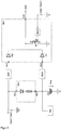
- a vehicle electrical system of a motor vehicle comprises a first and a second energy system Esys1, Esys2, as well as a device V arranged in the negative current path of the vehicle electrical system.
- the energy systems Esys1, Esys2 in this exemplary vehicle electrical system are not isolated from one another, ie they are non-electrically connected.
- the device V can also be arranged in a vehicle electrical system with separate potential energy systems Esys1, Esys2. Likewise, the device V can be arranged not only in the negative current path of the electrical system, but also in the positive current path of the electrical system.
- the first energy system Esys1 comprises a generator G, an energy storage ES1 and a group of electricity consumers such. B lamps or motor starters, which are collectively called system load LA.
- the preferably designed as a three-phase machine with downstream rectifier circuit generator G is used as energy converter for converting the kinetic energy from the vehicle into the electrical energy and at the same time as an energy source for supplying the system load LA with the electrical energy.
- the energy storage ES1 ie the first energy storage in the electrical system, stores the electrical energy converted by the generator G and supplies the system load LA with the stored electrical energy.
- the second energy system Esys2 the on-board network includes another so second energy storage ES2 of the electrical system, which is preferably designed as a double-layer capacitor and also serves to supply the system load LA with the stored electrical energy.
- the two energy systems Esys1, Esys2 have different nominal voltages Vsys1, Vsys2 as system voltages.
- the first energy storage ES1 with, for example, one or more 12V batteries or Li cells in a group circuit serves as an energy or power source for the normal load of the system load LA such. B. alternator.
- the second energy storage ES2 serves as an energy or power source for the high-current consumers of the system load LA such. B. motor starter.
- V or V ⁇ The control of the current flow between these two energy systems is effected by a device V or V ⁇ .
- the device V, V ' has a first recharging device NL1, with which the device V, V' charges the second energy store ES2 with the electrical energy from the first energy store ES1 or the generator G. If necessary, the device V, V ' also charges the first energy store ES1 with the electrical energy from the second energy store ES2.
- the recharging device NL1 has a DC / DC converter for converting the system voltage Vsys1 of the energy-giving energy system Esys1 into the system voltage Vsys2 of the energy store Esys2 currently to be charged, in order to charge the energy store Esys2 to the desired state of charge.
- the device V, V ' has a first and a second independently controllable switch S1, S2 which, for example, are designed as normally-off MOSFETs and which are connected to the gate Connection GS applied gate voltage controlled / opened.
- the device V, V ' In order to electrically connect the first energy store ES1 to the system load LA, the device V, V 'closes the first switch S1. To disconnect the electrical connection between the first energy store ES1 and the system load LA, the device V, V 'opens the first switch S1.
- the power consumers LA in the vehicle electrical system are supplied with power by closing the first switch S1 from the generator G and the first energy store ES1 of the first energy system Esys1.
- the generator G and the first energy storage ES1 largely maintain a stable mains voltage in the electrical system.
- the second energy system Esys2 with the second energy storage ES2 must be closed or fed into the electrical system.
- the device electrically connects or disconnects the second energy system Esys2 or the second energy store ES2 of the second energy system Esys2 with the first energy system Esys1 or the first energy store ES1 and the system load LA of the first energy system Esys1, respectively, with the first and second switches S1, S2.
- the device V, V ⁇ By simultaneously closing the second switch S2 and opening the first switch S1, the device V, V ⁇ connects the second energy system Esys2 or the second energy store ES2 of the second energy system Esys2 with the first energy system Esys1 or the first energy store ES1 and the system load LA of the second first power system ES1 electric and thus maintains the mains voltage in the electrical system.
- the device V By opening the second switch S2, the device V separates the second energy system Esys2 or the second energy store ES2 from the first energy system Esys1 or from the first energy store ES1 and the system load LA.
- the device V, V 'further comprises a control device SE1, SE1' for controlling the first switch 1, a rechargeable battery as an emergency power source NQ, a second recharging NL2, NL2 'for the emergency power source NQ, a diagnostic device DN for diagnosing the functionality or for monitoring the state of charge of the emergency power source NQ on.
- the device V of the first electrical system in the FIGS. 1 . 2 two voltage conversion devices SW1, SW3, with which the device V from the system voltage Vsys1 of the first energy system Esys1 or the voltage Ves1 of the first energy store ES1 and from the voltage Vnq of the emergency power source NQ generates the gate voltage Vgs1 for controlling the first switch S1.
- the two voltage conversion devices SW1, SW3 can be designed overall as DC / DC converters of the same type with manually and independently adjustable conversion coefficients, but also as DC / DC converters of different types with different conversion coefficients.
- the control of the first MOSFET switch S1 is effected by the control device SE1, which provides the gate voltage Vgs1 for the switch S1 as an output signal at the output K24 of the device SE1.
- the control device SE1 With two signal inputs K21, K23, the control device SE1 is electrically connected to the respective output of the two voltage conversion devices SW1, SW3, which in turn are electrically connected on the input side to the respective positive terminal of the first energy storage Esys1 and the emergency power source NQ.
- the voltage conversion in the two voltage conversion devices SW1, SW3 is carried out as a percentage, that is, the output voltage Ua is proportional to the input voltage Ua, wherein the ratios of the output voltages Ua to the respective input voltages Ue in all two voltage conversion devices SW1, SW3 are adjustable by adjusting the adjustable conversion coefficients k ,
- the output voltages from the two voltage conversion devices SW1, SW3 are forwarded by the control device SE1 to the gate terminal GS1 of the first switch S1.
- control device SE1 has two diodes D1, D2, which are electrically connected with their anode terminal to the respective output of the voltage conversion devices SW3, SW1 and with its cathode terminal to the gate terminal GS1 of the first switch S1, and the current from the outputs of the respective voltage conversion means SW3, SW1 to the gate terminal GS1 of the first switch S1 out and reverse reverse.
- control device SE1 between the node K24 so between the gate terminal of the first switch S1 and the ground potential on a third controllable, also designed as a self-blocking MOSFET switch S3.
- this third switch S3 is controlled by an intermediate control unit SH, this control unit SH monitors the current flow in the electrical system (eg at the first switch S1) and at strongly increasing current flow or when exceeding the current value in the electrical system (or first switch S1) closes the third switch S3 via a predetermined nominal current value and thus sets the gate voltage Vgs1 of the first switch S1 to the ground potential.
- the control unit SH holds the third switch S3 in an open state and the gate voltage Vgs1 of the first switch S1 to the voltage level of the output voltage of the voltage conversion devices SW1, SW3.
- the system voltage Vsys1 of the first energy system ES1 or the voltage Ves1 at the first energy store ES1 is higher than or equal to a minimum voltage required for a stable system state in the electrical system (nominal voltage).
- the output voltage from the first voltage converting device SW1, which is forwarded unchanged from the first diode D1 of the controller SE1 to the gate terminal GS1, is higher than the target gate voltage Vsgs1 required for closing the switch S1, so that the first switch S1 is closed is held in the closed state and the current from the first energy storage ES1 to the system load LA directs.
- the control unit SH opens the third switch S3 and holds the third switch S3 in an open state, so that the gate voltage Vgs1 of the first switch S1 is maintained at the voltage level of the output voltage of the voltage conversion device SW1.
- the second control device SE2 holds the second switch S2 in the opened state.
- control unit SH sets its output voltage to a required to close the third switch S3 voltage level and thus closes the third switch S3.
- the gate terminal GS1 of the first switch S1 is set at the ground potential. Consequently, the first switch S1 is opened and the current flow from the first energy store ES1 is interrupted by this first switch S1 toward the system load LA.
- the second control device SE2 closes the second switch S2 and thus connects the second energy system Esys2 or the second energy store ES2 to the first energy system Esys1 or to the first energy store ES1 and the system load LA.
- a current path from the first energy store ES1 is established via the second switch S2 to the second energy store ES2 and then to the system load LA, and the grid voltage is kept at a voltage potential required to operate the system load LA thanks to the second energy store ES2.
- the system voltage Vsys1 on the first energy system Esys1 or the voltage on the first energy store ES1 breaks down in an uncontrolled manner without a current increase in the vehicle electrical system being recorded. In this case, the output voltage of the first voltage conversion device SW1 falls below the target gate voltage Vsgs.
- the first switch S1 threatens to open and the current flow from the first energy store ES1 to be interrupted via this first switch S1 to the system load LA.
- control unit SH is powered by the first energy storage ES1 with the power, the control unit SH will no longer work when canceling the system voltage at the first energy storage ES1 due to the lack of operating voltage. As a result, the control voltage thus drops the gate voltage for the third switch S3 and the third switch S3 designed as a self-blocking MOSFET opens automatically.
- the operating voltage at the second control device Due to the drop in the system voltage Vsys1, the operating voltage at the second control device also drops and thus also the gate voltage for the second switch S2.
- the trained as a self-blocking MOSFET second switch S2 opens automatically. This is desired so that the second energy system Esys2 or the second energy storage ES2 is not connected to the faulty vehicle electrical system.
- a parasitic current injection Ii which flows through the MOSFET internal parasitic diode path DS2 of the opened second switch S2 through to the second energy system Esys2, flows uncontrolled in the faulty first energy system Esys1, for example, to overheat of the second switch S2 and on the other hand to Uncontrolled overcharging of the second energy storage ES2 can lead.
- This current injection Ii can simply be dissipated to ground by means of the current path through the closed first switch S1 and made harmless.
- the normally-off third switch S3 opens automatically, and thus the gate terminal of the first switch S1 does not become too shorted to ground.
- the first switch S1 is closed or held in a closed state when a system fault occurs in the first energy system Esys1, and the parasitic current injection Ii from the first energy system Esys1 is dissipated to ground by this first switch S1 and rendered harmless.
- parasitic charging or overcharging from the second energy storage ES2 and system overheating at the second switch S2 or within the device V can be prevented.
- the entire vehicle electrical system can be kept in a safe state despite the system error.
- the emergency power source NQ can be charged from the first energy system Esys1 or from the first energy storage ES1 of the first energy system Esys1 in a nominal fault-free system state with the current.
- the state of charge of the emergency power source NQ or the charging process with the emergency power source NQ can be monitored and controlled by the diagnostic device DN.
- the in the FIGS. 3 to 5 represented device V 'differs from that in the FIGS. 1 and 2 represented device V, characterized in that the first switch S1 in addition to the voltage from the first energy storage ES1 and the voltage from the emergency power source NQ is still controlled by the voltage Vsys2 of the second energy system Esys2 or by the voltage Ves2 of the second energy storage ES2.
- the device V ' has a further voltage conversion device SW2, which converts the voltage Vsys2 of the second energy system Esys2 or the voltage Ves2 of the second energy store ES2 in a control voltage.
- This converted control voltage is forwarded by a further diode D3 to the gate terminal GS1 of the first switch S1 and controls the first switch S1 as a gate voltage Vgs1.
- a redundant control path is provided for the first switch S1, which in the fault state at the first energy system Esys1 next to the control path from the emergency power source NQ also serves to close or hold the first switch S1 in the closed state.
- the emergency power source NQ can be charged in this case, both from the first and the second energy storage ES1, ES2 with the current.
- the recharging device NL2 'each have a connection K31, K32 to the respective energy store ES1, ES2.
- the recharging device NL2 ' has in each case a diode and a recharging unit comprising a resistor.
Landscapes
- Engineering & Computer Science (AREA)
- Mechanical Engineering (AREA)
- Power Engineering (AREA)
- Chemical & Material Sciences (AREA)
- Combustion & Propulsion (AREA)
- General Engineering & Computer Science (AREA)
- Transportation (AREA)
- Charge And Discharge Circuits For Batteries Or The Like (AREA)
Claims (9)
- Réseau de bord pour un véhicule, possédant les caractéristiques suivantes :- un premier trajet de courant comprenant :∘ au moins un consommateur de courant (LA),∘ un premier accumulateur d'énergie (ES1) et∘ un premier commutateur (S1) à autoverrouillage qui peut être commandé au moyen d'une première tension de commande,l'au moins un consommateur de courant (LA) pouvant être relié électriquement au premier accumulateur d'énergie (ES1) dans une position fermée du premier commutateur (S1),- un deuxième trajet de courant comprenant :∘ l'au moins un consommateur de courant (LA),∘ le premier (ES1) et un deuxième accumulateur d'énergie (ES2) et∘ un deuxième commutateur (S2) qui peut être commandé au moyen d'une deuxième tension de commande,l'au moins un consommateur de courant (LA) pouvant être relié électriquement au premier (ES1) et au deuxième accumulateur d'énergie (ES2) dans une position fermée du deuxième commutateur (S2),- un dispositif de commande (SE1) destiné à fermer le premier commutateur (S1) ou à maintenir le premier commutateur (S1) à l'état fermé dans le cas où la tension délivrée par l'accumulateur d'énergie (ES1), alimentant le premier commutateur (S1), devient inférieure à une valeur de seuil de tension minimale nécessaire pour fermer ou pour maintenir à l'état fermé le premier commutateur (S1).
- Réseau de bord selon la revendication 1, comprenant une source électrique de secours (NQ) destinée à délivrer la tension nécessaire pour fermer le premier commutateur (S1) ou maintenir le premier commutateur (S1) à l'état fermé, le dispositif de commande (SE1) étant réalisé pour fermer ou maintenir le premier commutateur (S1) à l'état fermé avec la tension délivrée par la source électrique de secours (NQ).
- Réseau de bord selon l'une des revendications précédentes, le premier (ES1) et le deuxième accumulateur d'énergie (ES2) étant réalisés pour ne pouvoir être reliés électriquement au consommateur de courant (LA) que dans l'état ouvert du premier commutateur (S1) et dans l'état simultanément fermé du deuxième commutateur (S2).
- Réseau de bord selon l'une des revendications précédentes, le dispositif de commande (SE1) étant réalisé pour fermer et pour maintenir le premier commutateur (S1) à l'état fermé avec la tension délivrée par la source électrique de secours (NQ) seulement lorsque le deuxième commutateur (S2) se trouve à l'état ouvert.
- Réseau de bord selon l'une des revendications précédentes 2 à 4, le dispositif de commande (SE1) étant réalisé pour fermer et pour maintenir le premier commutateur (S1) à l'état fermé en fonction de la tension de la source électrique de secours (NQ) et en fonction d'au moins l'une des tensions du premier (ES1) et du deuxième accumulateur d'énergie (E2), au choix, avec la tension de la source électrique de secours (NQ), ou avec la tension du premier (ES1) et du deuxième accumulateur d'énergie (ES2).
- Réseau de bord selon l'une des revendications précédentes, dans lequel :- le premier commutateur (S1) possède une borne de commande (GS1) pour la tension de commande et- le dispositif de commande (SE1) possède∘ une première vanne électrique (D1), notamment une diode, disposée entre la borne de commande (GS1) du premier commutateur (S1) et la source électrique de secours (NQ), passante en direction de la borne de commande (GS1) du premier commutateur (S1) et bloquée en sens inverse, et/ou∘ une deuxième vanne électrique (D2), notamment une diode, disposée entre la borne de commande (GS1) du premier commutateur (S1) et le premier accumulateur d'énergie (ES1), passante en direction de la borne de commande (GS1) du premier commutateur (S1) et bloquée en sens inverse, et/ou∘ une troisième vanne électrique (D3), notamment une diode, disposée entre la borne de commande (GS1) du premier commutateur (S1) et le deuxième accumulateur d'énergie (ES2), passante en direction de la borne de commande (GS1) du premier commutateur (S1) et bloquée en sens inverse.
- Réseau de bord selon l'une des revendications 2 à 6, dans lequel :- la source électrique de secours (NQ) est un accumulateur rechargeable, et- le réseau de bord possède, entre le premier (ES1) et/ou le deuxième accumulateur d'énergie (ES2) et la source électrique de secours (NQ) une première (NL2, NL1) et/ou une deuxième unité de recharge (NL22) destinées à charger la source électrique de secours (NQ) avec le courant du premier (ES1) et/ou du deuxième accumulateur d'énergie (ES2).
- Réseau de bord selon l'une des revendications précédentes, dans lequel :- le dispositif de commande (SE1)∘ possède un troisième commutateur (S3) commandable entre la borne de commande (GS1) du premier commutateur (S1) et la borne de masse,∘ une unité de commande (SH) servant à commander le troisième commutateur (S3),- cette unité de commande (SH) étant réalisée∘ pour détecter une valeur de courant actuelle au niveau du trajet de courant du premier accumulateur d'énergie (ES1) vers le consommateur de courant (LA), notamment au niveau du premier accumulateur d'énergie (ES1),∘ pour comparer la valeur du courant actuellement détectée avec une valeur de courant de consigne prédéfinie, et∘ pour fermer le troisième commutateur (S3) dans le cas où la valeur du courant actuellement détectée dépasse la valeur de courant de consigne et pour appliquer la tension de commande du premier commutateur (S1) à la masse.
- Véhicule, notamment véhicule automobile équipé d'un réseau de bord selon l'une des revendications 1 à 8.
Priority Applications (1)
| Application Number | Priority Date | Filing Date | Title |
|---|---|---|---|
| EP17156372.9A EP3239517B1 (fr) | 2010-12-20 | 2011-12-12 | Dispositif de commande d'une circulation de courant dans un réseau de distribution de bord d'un véhicule |
Applications Claiming Priority (2)
| Application Number | Priority Date | Filing Date | Title |
|---|---|---|---|
| DE102010063598A DE102010063598A1 (de) | 2010-12-20 | 2010-12-20 | Bordnetz für ein Fahrzeug sowie Vorrichtung zur Steuerung eines Stromflusses in einem Bordnetz eines Fahrzeugs |
| PCT/EP2011/072414 WO2012084565A1 (fr) | 2010-12-20 | 2011-12-12 | Réseau de bord pour un véhicule et dispositif pour la commande d'un flux de courant dans un réseau de bord de véhicule |
Related Child Applications (2)
| Application Number | Title | Priority Date | Filing Date |
|---|---|---|---|
| EP17156372.9A Division EP3239517B1 (fr) | 2010-12-20 | 2011-12-12 | Dispositif de commande d'une circulation de courant dans un réseau de distribution de bord d'un véhicule |
| EP17156372.9A Division-Into EP3239517B1 (fr) | 2010-12-20 | 2011-12-12 | Dispositif de commande d'une circulation de courant dans un réseau de distribution de bord d'un véhicule |
Publications (2)
| Publication Number | Publication Date |
|---|---|
| EP2655859A1 EP2655859A1 (fr) | 2013-10-30 |
| EP2655859B1 true EP2655859B1 (fr) | 2018-02-28 |
Family
ID=45315815
Family Applications (2)
| Application Number | Title | Priority Date | Filing Date |
|---|---|---|---|
| EP17156372.9A Active EP3239517B1 (fr) | 2010-12-20 | 2011-12-12 | Dispositif de commande d'une circulation de courant dans un réseau de distribution de bord d'un véhicule |
| EP11794169.0A Active EP2655859B1 (fr) | 2010-12-20 | 2011-12-12 | Réseau de bord pour un véhicule |
Family Applications Before (1)
| Application Number | Title | Priority Date | Filing Date |
|---|---|---|---|
| EP17156372.9A Active EP3239517B1 (fr) | 2010-12-20 | 2011-12-12 | Dispositif de commande d'une circulation de courant dans un réseau de distribution de bord d'un véhicule |
Country Status (4)
| Country | Link |
|---|---|
| US (1) | US9487089B2 (fr) |
| EP (2) | EP3239517B1 (fr) |
| DE (1) | DE102010063598A1 (fr) |
| WO (1) | WO2012084565A1 (fr) |
Families Citing this family (10)
| Publication number | Priority date | Publication date | Assignee | Title |
|---|---|---|---|---|
| DE102010063598A1 (de) | 2010-12-20 | 2012-06-21 | Continental Automotive Gmbh | Bordnetz für ein Fahrzeug sowie Vorrichtung zur Steuerung eines Stromflusses in einem Bordnetz eines Fahrzeugs |
| DE102012200804A1 (de) * | 2012-01-20 | 2013-07-25 | Continental Automotive Gmbh | Bordnetz und Verfahren zum Betreiben eines Bordnetzes |
| EP3013617A4 (fr) * | 2013-06-28 | 2017-11-08 | CAP-XX Limited | Système de commande pour un moteur automobile et procédé de commande d'un moteur automobile |
| DE102013221579A1 (de) * | 2013-10-24 | 2015-04-30 | Zf Friedrichshafen Ag | Elektronische Vorrichtung und Verfahren zum Betreiben einer elektronischen Vorrichtung |
| DE102014208257A1 (de) * | 2014-04-30 | 2015-11-05 | Continental Automotive Gmbh | Stabilisierungsschaltung für ein Bordnetz |
| CN104393565A (zh) * | 2014-12-04 | 2015-03-04 | 京东方科技集团股份有限公司 | 过热保护装置、方法和电气设备 |
| JP6638616B2 (ja) * | 2016-09-30 | 2020-01-29 | 株式会社デンソー | 電源制御装置 |
| JP6789780B2 (ja) * | 2016-11-28 | 2020-11-25 | 株式会社 日立パワーデバイス | 整流器およびそれを用いたオルタネータ |
| CN114189006B (zh) * | 2019-06-26 | 2024-04-19 | 深圳市华思旭科技有限公司 | 应急启动电源及应急充电方法 |
| CN115133822B (zh) * | 2020-09-03 | 2025-04-18 | 福建永强力加动力设备有限公司 | 一种柴油发电机启动控制电路 |
Family Cites Families (7)
| Publication number | Priority date | Publication date | Assignee | Title |
|---|---|---|---|---|
| DE10305357B4 (de) | 2003-02-10 | 2005-12-22 | Siemens Ag | Vorrichtung zur Energieversorgung eines mit sicherheitsrelevanten Komponenten ausgestatteten Zweispannungs-Bordnetzes |
| JP4254658B2 (ja) | 2004-08-23 | 2009-04-15 | 株式会社デンソー | 車載電源システム |
| DE102006037699B4 (de) * | 2006-08-11 | 2011-03-10 | Man Nutzfahrzeuge Ag | Spannungsversorgungseinrichtung für Nutzfahrzeuge |
| FR2935073B1 (fr) * | 2008-08-13 | 2017-05-05 | Valeo Equip Electr Moteur | Dispositif electrique auxiliaire, notamment pour vehicule automobile |
| DE102008054720A1 (de) * | 2008-12-16 | 2010-06-17 | Robert Bosch Gmbh | Vorrichtung zum Zuführen elektrischer Energie zu Elektromotor |
| DE102009024374A1 (de) * | 2009-06-09 | 2010-12-16 | Audi Ag | Bordnetz für ein Kraftfahrzeug und Verfahren zum Betreiben eines elektrischen Verbrauchers |
| DE102010063598A1 (de) | 2010-12-20 | 2012-06-21 | Continental Automotive Gmbh | Bordnetz für ein Fahrzeug sowie Vorrichtung zur Steuerung eines Stromflusses in einem Bordnetz eines Fahrzeugs |
-
2010
- 2010-12-20 DE DE102010063598A patent/DE102010063598A1/de not_active Withdrawn
-
2011
- 2011-12-12 EP EP17156372.9A patent/EP3239517B1/fr active Active
- 2011-12-12 EP EP11794169.0A patent/EP2655859B1/fr active Active
- 2011-12-12 WO PCT/EP2011/072414 patent/WO2012084565A1/fr not_active Ceased
- 2011-12-12 US US13/996,398 patent/US9487089B2/en active Active
Also Published As
| Publication number | Publication date |
|---|---|
| EP3239517A1 (fr) | 2017-11-01 |
| DE102010063598A1 (de) | 2012-06-21 |
| US9487089B2 (en) | 2016-11-08 |
| EP2655859A1 (fr) | 2013-10-30 |
| EP3239517B1 (fr) | 2019-03-13 |
| US20130300193A1 (en) | 2013-11-14 |
| WO2012084565A1 (fr) | 2012-06-28 |
Similar Documents
| Publication | Publication Date | Title |
|---|---|---|
| EP2655859B1 (fr) | Réseau de bord pour un véhicule | |
| EP2440432B1 (fr) | Circuit et méthode de commande pour rupport du tension dans un réseau de bord d'un véhicule | |
| DE102016102417B4 (de) | Schutzschaltung für ein Photovoltaik (PV)-Modul, Verfahren zum Betrieb der Schutzschaltung und Photovoltaik (PV)-Anlage mit einer derartigen Schutzschaltung | |
| DE102016005565B4 (de) | Schaltungsanordnung für eine Zwischenkreiskapazität, Kraftfahrzeug mit einer solchen Schaltungsanordnung sowie Verfahren zum Vorladen einer Zwischenkreiskapazität und Verfahren zum Ausgleichen von Batterieladezuständen parallel geschalteter Batteriemodule | |
| EP2435279B1 (fr) | Réseau de bord pour un véhicule ainsi que dispositif de commande pour un réseau de bord | |
| DE112017006219B4 (de) | Fahrzeugmontierte Energieversorgungsvorrichtung | |
| EP2953227A1 (fr) | Réseau de bord pour un véhicule automobile | |
| DE102017222557B4 (de) | Mehrspannungsbatterievorrichtung und Bordnetz für ein Kraftfahrzeug | |
| DE112012007029T5 (de) | Energieversorgungs-Handhabungssystem und Energieversorgungs-Handhabungsverfahren | |
| EP1520752B1 (fr) | Réseau de bord à stratégie de recharge améliorée de la batterie supplémentaire et méthode correspondante | |
| EP2553257B1 (fr) | Réseau de bord pour véhicule et dispositif de commande pour réguler un flux de courant dans un réseau de bord de véhicule | |
| WO2016113298A1 (fr) | Batterie haute tension destinée à un véhicule automobile et véhicule automobile | |
| EP2843784A2 (fr) | Commutation d'entraînement pour un moteur monté sur coussin d'air | |
| EP2845283A1 (fr) | Module d'alimentation en énergie conçu en dipôle, utilisation d'un dispositif de séparation dans un tel module d'alimentation en énergie et procédé de fonctionnement d'un tel module d'alimentation en énergie | |
| EP2582009A1 (fr) | Système de stockage d'énergie avec algorithme de réglage implémenté et procédé de commande de l'état de chargement de ses éléments | |
| EP2314861A1 (fr) | Réseau de bord pour un véhicule automobile | |
| EP2553789B1 (fr) | Circuit électrique de véhicule et dispositif de commande pour stabiliser sa tension | |
| DE102016006660B4 (de) | Verfahren zum Betreiben eines Kraftfahrzeugs mit einem Verbrennungsmotor und mit zwei elektrischen, über einen Gleichspannungswandler gekoppelten Bordnetzen und Kraftfahrzeug mit einer Steuereinrichtung zum Durchführen des Verfahrens | |
| DE102015208568B4 (de) | Bordnetz-Schaltmodul, Bordnetzunterstützungseinrichtung und Bordnetzzweig | |
| WO2023041595A1 (fr) | Dispositif d'interconnexion et d'éléments à combustible pour une interconnexion efficace d'éléments à combustible et véhicule automobile | |
| WO2023041563A1 (fr) | Dispositif de commutation de précharge et dispositif de pile à combustible pour adapter de manière amortie la tension et le courant par rapport à une batterie montée en parallèle et véhicule automobile | |
| DE102012218596B4 (de) | Steuereinheit für ein Bordnetz, Bordnetz und Verfahren zum Betreiben eines Bordnetzes | |
| DE102014201196A1 (de) | Verfahren zum Betreiben eines Batteriemanagementsystems und Batteriemanagementsystem | |
| DE102005027211A1 (de) | DC-Stromversorgung | |
| DE102021210940A1 (de) | Anordnung umfassend zumindest zwei unterbrechungsfreie Stromversorgungen und Verfahren zu deren Betrieb |
Legal Events
| Date | Code | Title | Description |
|---|---|---|---|
| PUAI | Public reference made under article 153(3) epc to a published international application that has entered the european phase |
Free format text: ORIGINAL CODE: 0009012 |
|
| 17P | Request for examination filed |
Effective date: 20130722 |
|
| AK | Designated contracting states |
Kind code of ref document: A1 Designated state(s): AL AT BE BG CH CY CZ DE DK EE ES FI FR GB GR HR HU IE IS IT LI LT LU LV MC MK MT NL NO PL PT RO RS SE SI SK SM TR |
|
| DAX | Request for extension of the european patent (deleted) | ||
| 17Q | First examination report despatched |
Effective date: 20170127 |
|
| GRAP | Despatch of communication of intention to grant a patent |
Free format text: ORIGINAL CODE: EPIDOSNIGR1 |
|
| INTG | Intention to grant announced |
Effective date: 20170929 |
|
| GRAS | Grant fee paid |
Free format text: ORIGINAL CODE: EPIDOSNIGR3 |
|
| GRAA | (expected) grant |
Free format text: ORIGINAL CODE: 0009210 |
|
| AK | Designated contracting states |
Kind code of ref document: B1 Designated state(s): AL AT BE BG CH CY CZ DE DK EE ES FI FR GB GR HR HU IE IS IT LI LT LU LV MC MK MT NL NO PL PT RO RS SE SI SK SM TR |
|
| REG | Reference to a national code |
Ref country code: GB Ref legal event code: FG4D Free format text: NOT ENGLISH Ref country code: CH Ref legal event code: EP |
|
| REG | Reference to a national code |
Ref country code: AT Ref legal event code: REF Ref document number: 974439 Country of ref document: AT Kind code of ref document: T Effective date: 20180315 |
|
| REG | Reference to a national code |
Ref country code: IE Ref legal event code: FG4D Free format text: LANGUAGE OF EP DOCUMENT: GERMAN |
|
| REG | Reference to a national code |
Ref country code: DE Ref legal event code: R096 Ref document number: 502011013835 Country of ref document: DE |
|
| REG | Reference to a national code |
Ref country code: NL Ref legal event code: MP Effective date: 20180228 |
|
| REG | Reference to a national code |
Ref country code: LT Ref legal event code: MG4D |
|
| PG25 | Lapsed in a contracting state [announced via postgrant information from national office to epo] |
Ref country code: NL Free format text: LAPSE BECAUSE OF FAILURE TO SUBMIT A TRANSLATION OF THE DESCRIPTION OR TO PAY THE FEE WITHIN THE PRESCRIBED TIME-LIMIT Effective date: 20180228 Ref country code: CY Free format text: LAPSE BECAUSE OF FAILURE TO SUBMIT A TRANSLATION OF THE DESCRIPTION OR TO PAY THE FEE WITHIN THE PRESCRIBED TIME-LIMIT Effective date: 20180228 Ref country code: HR Free format text: LAPSE BECAUSE OF FAILURE TO SUBMIT A TRANSLATION OF THE DESCRIPTION OR TO PAY THE FEE WITHIN THE PRESCRIBED TIME-LIMIT Effective date: 20180228 Ref country code: NO Free format text: LAPSE BECAUSE OF FAILURE TO SUBMIT A TRANSLATION OF THE DESCRIPTION OR TO PAY THE FEE WITHIN THE PRESCRIBED TIME-LIMIT Effective date: 20180528 Ref country code: FI Free format text: LAPSE BECAUSE OF FAILURE TO SUBMIT A TRANSLATION OF THE DESCRIPTION OR TO PAY THE FEE WITHIN THE PRESCRIBED TIME-LIMIT Effective date: 20180228 Ref country code: LT Free format text: LAPSE BECAUSE OF FAILURE TO SUBMIT A TRANSLATION OF THE DESCRIPTION OR TO PAY THE FEE WITHIN THE PRESCRIBED TIME-LIMIT Effective date: 20180228 Ref country code: ES Free format text: LAPSE BECAUSE OF FAILURE TO SUBMIT A TRANSLATION OF THE DESCRIPTION OR TO PAY THE FEE WITHIN THE PRESCRIBED TIME-LIMIT Effective date: 20180228 |
|
| PG25 | Lapsed in a contracting state [announced via postgrant information from national office to epo] |
Ref country code: LV Free format text: LAPSE BECAUSE OF FAILURE TO SUBMIT A TRANSLATION OF THE DESCRIPTION OR TO PAY THE FEE WITHIN THE PRESCRIBED TIME-LIMIT Effective date: 20180228 Ref country code: SE Free format text: LAPSE BECAUSE OF FAILURE TO SUBMIT A TRANSLATION OF THE DESCRIPTION OR TO PAY THE FEE WITHIN THE PRESCRIBED TIME-LIMIT Effective date: 20180228 Ref country code: RS Free format text: LAPSE BECAUSE OF FAILURE TO SUBMIT A TRANSLATION OF THE DESCRIPTION OR TO PAY THE FEE WITHIN THE PRESCRIBED TIME-LIMIT Effective date: 20180228 Ref country code: BG Free format text: LAPSE BECAUSE OF FAILURE TO SUBMIT A TRANSLATION OF THE DESCRIPTION OR TO PAY THE FEE WITHIN THE PRESCRIBED TIME-LIMIT Effective date: 20180528 Ref country code: GR Free format text: LAPSE BECAUSE OF FAILURE TO SUBMIT A TRANSLATION OF THE DESCRIPTION OR TO PAY THE FEE WITHIN THE PRESCRIBED TIME-LIMIT Effective date: 20180529 |
|
| PG25 | Lapsed in a contracting state [announced via postgrant information from national office to epo] |
Ref country code: MT Free format text: LAPSE BECAUSE OF FAILURE TO SUBMIT A TRANSLATION OF THE DESCRIPTION OR TO PAY THE FEE WITHIN THE PRESCRIBED TIME-LIMIT Effective date: 20180228 |
|
| PG25 | Lapsed in a contracting state [announced via postgrant information from national office to epo] |
Ref country code: AL Free format text: LAPSE BECAUSE OF FAILURE TO SUBMIT A TRANSLATION OF THE DESCRIPTION OR TO PAY THE FEE WITHIN THE PRESCRIBED TIME-LIMIT Effective date: 20180228 Ref country code: RO Free format text: LAPSE BECAUSE OF FAILURE TO SUBMIT A TRANSLATION OF THE DESCRIPTION OR TO PAY THE FEE WITHIN THE PRESCRIBED TIME-LIMIT Effective date: 20180228 Ref country code: IT Free format text: LAPSE BECAUSE OF FAILURE TO SUBMIT A TRANSLATION OF THE DESCRIPTION OR TO PAY THE FEE WITHIN THE PRESCRIBED TIME-LIMIT Effective date: 20180228 Ref country code: EE Free format text: LAPSE BECAUSE OF FAILURE TO SUBMIT A TRANSLATION OF THE DESCRIPTION OR TO PAY THE FEE WITHIN THE PRESCRIBED TIME-LIMIT Effective date: 20180228 Ref country code: PL Free format text: LAPSE BECAUSE OF FAILURE TO SUBMIT A TRANSLATION OF THE DESCRIPTION OR TO PAY THE FEE WITHIN THE PRESCRIBED TIME-LIMIT Effective date: 20180228 |
|
| REG | Reference to a national code |
Ref country code: DE Ref legal event code: R097 Ref document number: 502011013835 Country of ref document: DE |
|
| PG25 | Lapsed in a contracting state [announced via postgrant information from national office to epo] |
Ref country code: SM Free format text: LAPSE BECAUSE OF FAILURE TO SUBMIT A TRANSLATION OF THE DESCRIPTION OR TO PAY THE FEE WITHIN THE PRESCRIBED TIME-LIMIT Effective date: 20180228 Ref country code: SK Free format text: LAPSE BECAUSE OF FAILURE TO SUBMIT A TRANSLATION OF THE DESCRIPTION OR TO PAY THE FEE WITHIN THE PRESCRIBED TIME-LIMIT Effective date: 20180228 Ref country code: DK Free format text: LAPSE BECAUSE OF FAILURE TO SUBMIT A TRANSLATION OF THE DESCRIPTION OR TO PAY THE FEE WITHIN THE PRESCRIBED TIME-LIMIT Effective date: 20180228 Ref country code: CZ Free format text: LAPSE BECAUSE OF FAILURE TO SUBMIT A TRANSLATION OF THE DESCRIPTION OR TO PAY THE FEE WITHIN THE PRESCRIBED TIME-LIMIT Effective date: 20180228 |
|
| PLBE | No opposition filed within time limit |
Free format text: ORIGINAL CODE: 0009261 |
|
| STAA | Information on the status of an ep patent application or granted ep patent |
Free format text: STATUS: NO OPPOSITION FILED WITHIN TIME LIMIT |
|
| 26N | No opposition filed |
Effective date: 20181129 |
|
| PG25 | Lapsed in a contracting state [announced via postgrant information from national office to epo] |
Ref country code: SI Free format text: LAPSE BECAUSE OF FAILURE TO SUBMIT A TRANSLATION OF THE DESCRIPTION OR TO PAY THE FEE WITHIN THE PRESCRIBED TIME-LIMIT Effective date: 20180228 |
|
| REG | Reference to a national code |
Ref country code: CH Ref legal event code: PL |
|
| GBPC | Gb: european patent ceased through non-payment of renewal fee |
Effective date: 20181212 |
|
| PG25 | Lapsed in a contracting state [announced via postgrant information from national office to epo] |
Ref country code: LU Free format text: LAPSE BECAUSE OF NON-PAYMENT OF DUE FEES Effective date: 20181212 Ref country code: MC Free format text: LAPSE BECAUSE OF FAILURE TO SUBMIT A TRANSLATION OF THE DESCRIPTION OR TO PAY THE FEE WITHIN THE PRESCRIBED TIME-LIMIT Effective date: 20180228 |
|
| REG | Reference to a national code |
Ref country code: IE Ref legal event code: MM4A |
|
| REG | Reference to a national code |
Ref country code: BE Ref legal event code: MM Effective date: 20181231 |
|
| PG25 | Lapsed in a contracting state [announced via postgrant information from national office to epo] |
Ref country code: IE Free format text: LAPSE BECAUSE OF NON-PAYMENT OF DUE FEES Effective date: 20181212 |
|
| PG25 | Lapsed in a contracting state [announced via postgrant information from national office to epo] |
Ref country code: BE Free format text: LAPSE BECAUSE OF NON-PAYMENT OF DUE FEES Effective date: 20181231 |
|
| PG25 | Lapsed in a contracting state [announced via postgrant information from national office to epo] |
Ref country code: GB Free format text: LAPSE BECAUSE OF NON-PAYMENT OF DUE FEES Effective date: 20181212 Ref country code: CH Free format text: LAPSE BECAUSE OF NON-PAYMENT OF DUE FEES Effective date: 20181231 Ref country code: LI Free format text: LAPSE BECAUSE OF NON-PAYMENT OF DUE FEES Effective date: 20181231 |
|
| REG | Reference to a national code |
Ref country code: AT Ref legal event code: MM01 Ref document number: 974439 Country of ref document: AT Kind code of ref document: T Effective date: 20181212 |
|
| PG25 | Lapsed in a contracting state [announced via postgrant information from national office to epo] |
Ref country code: TR Free format text: LAPSE BECAUSE OF FAILURE TO SUBMIT A TRANSLATION OF THE DESCRIPTION OR TO PAY THE FEE WITHIN THE PRESCRIBED TIME-LIMIT Effective date: 20180228 |
|
| PG25 | Lapsed in a contracting state [announced via postgrant information from national office to epo] |
Ref country code: AT Free format text: LAPSE BECAUSE OF NON-PAYMENT OF DUE FEES Effective date: 20181212 |
|
| PG25 | Lapsed in a contracting state [announced via postgrant information from national office to epo] |
Ref country code: PT Free format text: LAPSE BECAUSE OF FAILURE TO SUBMIT A TRANSLATION OF THE DESCRIPTION OR TO PAY THE FEE WITHIN THE PRESCRIBED TIME-LIMIT Effective date: 20180228 |
|
| REG | Reference to a national code |
Ref country code: DE Ref legal event code: R081 Ref document number: 502011013835 Country of ref document: DE Owner name: VITESCO TECHNOLOGIES GMBH, DE Free format text: FORMER OWNER: CONTINENTAL AUTOMOTIVE GMBH, 30165 HANNOVER, DE |
|
| PG25 | Lapsed in a contracting state [announced via postgrant information from national office to epo] |
Ref country code: HU Free format text: LAPSE BECAUSE OF FAILURE TO SUBMIT A TRANSLATION OF THE DESCRIPTION OR TO PAY THE FEE WITHIN THE PRESCRIBED TIME-LIMIT; INVALID AB INITIO Effective date: 20111212 Ref country code: MK Free format text: LAPSE BECAUSE OF NON-PAYMENT OF DUE FEES Effective date: 20180228 |
|
| PG25 | Lapsed in a contracting state [announced via postgrant information from national office to epo] |
Ref country code: IS Free format text: LAPSE BECAUSE OF FAILURE TO SUBMIT A TRANSLATION OF THE DESCRIPTION OR TO PAY THE FEE WITHIN THE PRESCRIBED TIME-LIMIT Effective date: 20180628 |
|
| REG | Reference to a national code |
Ref country code: DE Ref legal event code: R084 Ref document number: 502011013835 Country of ref document: DE |
|
| REG | Reference to a national code |
Ref country code: DE Ref legal event code: R081 Ref document number: 502011013835 Country of ref document: DE Owner name: SCHAEFFLER TECHNOLOGIES AG & CO. KG, DE Free format text: FORMER OWNER: VITESCO TECHNOLOGIES GMBH, 30165 HANNOVER, DE Ref country code: DE Ref legal event code: R081 Ref document number: 502011013835 Country of ref document: DE Owner name: VITESCO TECHNOLOGIES GMBH, DE Free format text: FORMER OWNER: VITESCO TECHNOLOGIES GMBH, 30165 HANNOVER, DE |
|
| P01 | Opt-out of the competence of the unified patent court (upc) registered |
Effective date: 20230530 |
|
| REG | Reference to a national code |
Ref country code: DE Ref legal event code: R081 Ref document number: 502011013835 Country of ref document: DE Owner name: SCHAEFFLER TECHNOLOGIES AG & CO. KG, DE Free format text: FORMER OWNER: VITESCO TECHNOLOGIES GMBH, 93055 REGENSBURG, DE |
|
| PGFP | Annual fee paid to national office [announced via postgrant information from national office to epo] |
Ref country code: FR Payment date: 20251223 Year of fee payment: 15 |
|
| PGFP | Annual fee paid to national office [announced via postgrant information from national office to epo] |
Ref country code: DE Payment date: 20251231 Year of fee payment: 15 |