EP2655867B1 - Arrangement et commande de groupe de turbine hydraulique - Google Patents
Arrangement et commande de groupe de turbine hydraulique Download PDFInfo
- Publication number
- EP2655867B1 EP2655867B1 EP11796790.1A EP11796790A EP2655867B1 EP 2655867 B1 EP2655867 B1 EP 2655867B1 EP 11796790 A EP11796790 A EP 11796790A EP 2655867 B1 EP2655867 B1 EP 2655867B1
- Authority
- EP
- European Patent Office
- Prior art keywords
- turbines
- water current
- arrangement
- turbine
- array
- Prior art date
- Legal status (The legal status is an assumption and is not a legal conclusion. Google has not performed a legal analysis and makes no representation as to the accuracy of the status listed.)
- Active
Links
- XLYOFNOQVPJJNP-UHFFFAOYSA-N water Substances O XLYOFNOQVPJJNP-UHFFFAOYSA-N 0.000 title claims description 69
- 238000010248 power generation Methods 0.000 claims description 21
- 238000005259 measurement Methods 0.000 claims description 20
- 238000000034 method Methods 0.000 claims description 13
- 238000011144 upstream manufacturing Methods 0.000 claims description 8
- 230000005611 electricity Effects 0.000 claims description 5
- 230000000694 effects Effects 0.000 claims description 4
- 230000007423 decrease Effects 0.000 description 3
- 238000010586 diagram Methods 0.000 description 2
- 239000002803 fossil fuel Substances 0.000 description 2
- 230000003993 interaction Effects 0.000 description 2
- 238000012856 packing Methods 0.000 description 2
- 230000005540 biological transmission Effects 0.000 description 1
- 230000001419 dependent effect Effects 0.000 description 1
- 230000006698 induction Effects 0.000 description 1
- 238000012544 monitoring process Methods 0.000 description 1
- 238000005457 optimization Methods 0.000 description 1
- 238000012545 processing Methods 0.000 description 1
- 238000012546 transfer Methods 0.000 description 1
Images


Classifications
-
- F—MECHANICAL ENGINEERING; LIGHTING; HEATING; WEAPONS; BLASTING
- F03—MACHINES OR ENGINES FOR LIQUIDS; WIND, SPRING, OR WEIGHT MOTORS; PRODUCING MECHANICAL POWER OR A REACTIVE PROPULSIVE THRUST, NOT OTHERWISE PROVIDED FOR
- F03B—MACHINES OR ENGINES FOR LIQUIDS
- F03B5/00—Machines or engines characterised by non-bladed rotors, e.g. serrated, using friction
-
- F—MECHANICAL ENGINEERING; LIGHTING; HEATING; WEAPONS; BLASTING
- F03—MACHINES OR ENGINES FOR LIQUIDS; WIND, SPRING, OR WEIGHT MOTORS; PRODUCING MECHANICAL POWER OR A REACTIVE PROPULSIVE THRUST, NOT OTHERWISE PROVIDED FOR
- F03B—MACHINES OR ENGINES FOR LIQUIDS
- F03B17/00—Other machines or engines
- F03B17/06—Other machines or engines using liquid flow with predominantly kinetic energy conversion, e.g. of swinging-flap type, "run-of-river", "ultra-low head"
-
- F—MECHANICAL ENGINEERING; LIGHTING; HEATING; WEAPONS; BLASTING
- F03—MACHINES OR ENGINES FOR LIQUIDS; WIND, SPRING, OR WEIGHT MOTORS; PRODUCING MECHANICAL POWER OR A REACTIVE PROPULSIVE THRUST, NOT OTHERWISE PROVIDED FOR
- F03B—MACHINES OR ENGINES FOR LIQUIDS
- F03B13/00—Adaptations of machines or engines for special use; Combinations of machines or engines with driving or driven apparatus; Power stations or aggregates
- F03B13/12—Adaptations of machines or engines for special use; Combinations of machines or engines with driving or driven apparatus; Power stations or aggregates characterised by using wave or tide energy
- F03B13/14—Adaptations of machines or engines for special use; Combinations of machines or engines with driving or driven apparatus; Power stations or aggregates characterised by using wave or tide energy using wave energy
- F03B13/22—Adaptations of machines or engines for special use; Combinations of machines or engines with driving or driven apparatus; Power stations or aggregates characterised by using wave or tide energy using wave energy using the flow of water resulting from wave movements to drive a motor or turbine
-
- F—MECHANICAL ENGINEERING; LIGHTING; HEATING; WEAPONS; BLASTING
- F03—MACHINES OR ENGINES FOR LIQUIDS; WIND, SPRING, OR WEIGHT MOTORS; PRODUCING MECHANICAL POWER OR A REACTIVE PROPULSIVE THRUST, NOT OTHERWISE PROVIDED FOR
- F03B—MACHINES OR ENGINES FOR LIQUIDS
- F03B13/00—Adaptations of machines or engines for special use; Combinations of machines or engines with driving or driven apparatus; Power stations or aggregates
- F03B13/12—Adaptations of machines or engines for special use; Combinations of machines or engines with driving or driven apparatus; Power stations or aggregates characterised by using wave or tide energy
- F03B13/26—Adaptations of machines or engines for special use; Combinations of machines or engines with driving or driven apparatus; Power stations or aggregates characterised by using wave or tide energy using tide energy
-
- F—MECHANICAL ENGINEERING; LIGHTING; HEATING; WEAPONS; BLASTING
- F03—MACHINES OR ENGINES FOR LIQUIDS; WIND, SPRING, OR WEIGHT MOTORS; PRODUCING MECHANICAL POWER OR A REACTIVE PROPULSIVE THRUST, NOT OTHERWISE PROVIDED FOR
- F03B—MACHINES OR ENGINES FOR LIQUIDS
- F03B13/00—Adaptations of machines or engines for special use; Combinations of machines or engines with driving or driven apparatus; Power stations or aggregates
- F03B13/12—Adaptations of machines or engines for special use; Combinations of machines or engines with driving or driven apparatus; Power stations or aggregates characterised by using wave or tide energy
- F03B13/26—Adaptations of machines or engines for special use; Combinations of machines or engines with driving or driven apparatus; Power stations or aggregates characterised by using wave or tide energy using tide energy
- F03B13/264—Adaptations of machines or engines for special use; Combinations of machines or engines with driving or driven apparatus; Power stations or aggregates characterised by using wave or tide energy using tide energy using the horizontal flow of water resulting from tide movement
-
- F—MECHANICAL ENGINEERING; LIGHTING; HEATING; WEAPONS; BLASTING
- F03—MACHINES OR ENGINES FOR LIQUIDS; WIND, SPRING, OR WEIGHT MOTORS; PRODUCING MECHANICAL POWER OR A REACTIVE PROPULSIVE THRUST, NOT OTHERWISE PROVIDED FOR
- F03B—MACHINES OR ENGINES FOR LIQUIDS
- F03B15/00—Controlling
-
- F—MECHANICAL ENGINEERING; LIGHTING; HEATING; WEAPONS; BLASTING
- F03—MACHINES OR ENGINES FOR LIQUIDS; WIND, SPRING, OR WEIGHT MOTORS; PRODUCING MECHANICAL POWER OR A REACTIVE PROPULSIVE THRUST, NOT OTHERWISE PROVIDED FOR
- F03B—MACHINES OR ENGINES FOR LIQUIDS
- F03B17/00—Other machines or engines
- F03B17/06—Other machines or engines using liquid flow with predominantly kinetic energy conversion, e.g. of swinging-flap type, "run-of-river", "ultra-low head"
- F03B17/061—Other machines or engines using liquid flow with predominantly kinetic energy conversion, e.g. of swinging-flap type, "run-of-river", "ultra-low head" with rotation axis substantially in flow direction
-
- F—MECHANICAL ENGINEERING; LIGHTING; HEATING; WEAPONS; BLASTING
- F05—INDEXING SCHEMES RELATING TO ENGINES OR PUMPS IN VARIOUS SUBCLASSES OF CLASSES F01-F04
- F05B—INDEXING SCHEME RELATING TO WIND, SPRING, WEIGHT, INERTIA OR LIKE MOTORS, TO MACHINES OR ENGINES FOR LIQUIDS COVERED BY SUBCLASSES F03B, F03D AND F03G
- F05B2240/00—Components
- F05B2240/40—Use of a multiplicity of similar components
-
- Y—GENERAL TAGGING OF NEW TECHNOLOGICAL DEVELOPMENTS; GENERAL TAGGING OF CROSS-SECTIONAL TECHNOLOGIES SPANNING OVER SEVERAL SECTIONS OF THE IPC; TECHNICAL SUBJECTS COVERED BY FORMER USPC CROSS-REFERENCE ART COLLECTIONS [XRACs] AND DIGESTS
- Y02—TECHNOLOGIES OR APPLICATIONS FOR MITIGATION OR ADAPTATION AGAINST CLIMATE CHANGE
- Y02E—REDUCTION OF GREENHOUSE GAS [GHG] EMISSIONS, RELATED TO ENERGY GENERATION, TRANSMISSION OR DISTRIBUTION
- Y02E10/00—Energy generation through renewable energy sources
- Y02E10/20—Hydro energy
-
- Y—GENERAL TAGGING OF NEW TECHNOLOGICAL DEVELOPMENTS; GENERAL TAGGING OF CROSS-SECTIONAL TECHNOLOGIES SPANNING OVER SEVERAL SECTIONS OF THE IPC; TECHNICAL SUBJECTS COVERED BY FORMER USPC CROSS-REFERENCE ART COLLECTIONS [XRACs] AND DIGESTS
- Y02—TECHNOLOGIES OR APPLICATIONS FOR MITIGATION OR ADAPTATION AGAINST CLIMATE CHANGE
- Y02E—REDUCTION OF GREENHOUSE GAS [GHG] EMISSIONS, RELATED TO ENERGY GENERATION, TRANSMISSION OR DISTRIBUTION
- Y02E10/00—Energy generation through renewable energy sources
- Y02E10/30—Energy from the sea, e.g. using wave energy or salinity gradient
Definitions
- the present invention relates to water current turbine arrangements, and, in particular, to a control scheme for water current turbine arrangements.
- the use of turbines to capture the power of water flow, such as tidal, river and ocean current flows is becoming a viable source of alternative energy.
- the turbine equipment used to capture such water flow energy typically includes a shaft driven generator connected using a drivetrain to a rotor assembly.
- the rotor assembly includes a plurality of rotor blades that are driven by the water flow, so as to turn an input shaft of the drivetrain.
- a tidal turbine farm may have tens to hundreds of turbines.
- the turbines are preferably arranged in an array having multiple rows of multiple turbines.
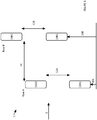
- Figure 1 of the accompanying drawings illustrates, in very simplified schematic form, a plan view of a turbine array 1.
- the turbine array 1 could be deployed in a tidal flow area, a river flow, an ocean current, or any other suitable water current area.
- it is preferable for the turbines to be arranged in an array geography, bathymetry and other factors may mean that a turbine farm has another arrangement.
- the exemplary turbine array 1 of Figure 1 comprises two rows (A and B) of two turbines 10A1, 10A2 and 10B1, 10B2 respectively.
- the number of turbines shown in Figure 1 has been limited to two in each row for the sake of clarity and simplicity. Similarly, the number of rows has been reduced to show the minimum number need to form an array. It will be readily appreciated that a practical array could have any number of rows, and any number of turbines per row.
- a water current is indicated by arrow 2, and flows in a direction such that Row A is upstream of Row B.
- the turbines in a row are spaced apart from one another by a turbine spacing 12A, 12B for the row concerned.
- This spacing may be the same for each row, or may vary between rows, and is to be considered a nominal value, as the exact spacing of turbines along a row is dependent on many factors including the nature of the bed on which the turbines are located.
- the rows are spaced apart by a row spacing 14, and, again, this spacing may be the same between each pair of adjacent rows in the array, or could vary across the array. As for turbine spacing, the row spacing is to be considered a nominal value. In addition, the row spacing can vary along the rows.
- the first turbine 10A1 in Row A is spaced from an arbitrary datum by a first offset value 16A, whilst the first turbine 10B1 of Row B is offset by a second offset value 16B.
- the first and second offset values 16A, 16B may be substantially equal to one another, in which case the turbine would effectively be lined up behind one another in the array, with respect to the direction of the flow. In a more practical example, however, the first and second offset values 16A, 16B would be different. Such different offset values leads to the turbines in Row B being offset, or staggered, with reference to the turbines in Row A. Such a situation is illustrated in Figure 1 .
- downstream turbines affect the amount of energy available for capture by downstream turbines, and the amount of energy available to the downstream turbines decreases as the row spacing decreases. It will be appreciated that downstream in the current context is any position having a component in the direction of the flow.
- WO 2004/111446 describes an arrangement in which axial induction of an upstream turbine is lowered to reduce turbulence at a downstream turbine.
- US 2007/0299548 describes a method for optimizing the operation of wind farms.
- US 2009/0099702 describes the optimization of wake interaction between wind turbines.
- the first and second pluralities of water current turbines may be arranged in respective first and second rows, so as to form an array.
- Such a method may further comprise receiving measurement information indicative of respective power generation characteristics of the turbines, and using received measurement information in controlling the turbines.
- Such a method may comprise controlling the power generation characteristics of the first plurality of water current turbines independently of the power generation characteristics of the second plurality of water current turbines.
- such a method may comprise defining groups of water current turbines, and controlling the power generation characteristics of water current turbines in one such group independently of turbines in another group.
- the water current turbine array may include at least one additional plurality of water current turbines arranged in an additional row of the array.
- Such a controller may further comprise a measurement receiver unit operable to receive measurement information indicative of respective power generation characteristics of the turbines, the control unit being operable to use received measurement information in generating the control signals relating to power generation characteristics.
- Such a controller may be operable to generate and output respective control signals to such a first plurality of water current turbines independently of generating and outputting respective control signals to such a second plurality of water current turbines.
- such a controller may be operable to define groups of water current turbines, and to generate and output respective control signals to water current turbines in one such group independently of turbines in another such group.
- FIG 2 is a block diagram of a water current turbine 10 embodying one aspect of the present invention, for use in a water current turbine array, such as that illustrated in Figure 1 .
- the water current turbine 10 includes a rotor assembly 20, which is arranged to be driven by the water current.
- the rotor assembly 20 rotates a shaft that transmits power to an electrical generator 22, which operates to generate electricity for supply to the power grid.
- the water current turbine 10 is provided with a controller unit 24, which operates to control the power generation characteristics of the electrical generator 22, so that the generator provides a required electrical power output.
- a measurement unit 26 is provided for monitoring the generator 22, and for providing measurement information regarding the power generating characteristics of the generator 22, in particular, and of the water current turbine 10 in general.
- the controller unit 24 and the measurement unit 26 are operable to transfer data with an array control unit (to be described with reference to Figure 4 ).
- FIG. 3 illustrates an array control unit 30 which includes a processor unit 32, which provides the overall processing functionality of the control unit 30.
- the processor unit 32 also provides a user interface 38 for interaction with the human controller of the system.
- the array control unit 30 also includes a measurement receiver unit 34 and a control signal transmitter unit 36.
- the measurement receiver unit 34 is operable to receive measurement information from the measurement units 26 in the water current turbines 10 shown in Figure 2 . Operating information may be gathered in any convenient manner, for example, the water current turbines may be polled individually at regular intervals, or may themselves operate to transmit information to the measurement receiver unit 34 of the array control unit 30.
- the control signal transmitter unit 36 is operable to transmit control information from the processor unit 32 to the controller units 24 in the water current turbines 10. This control information, as described in more detail below, serves to control the power generating characteristics and parameters of the water current turbine 10.
- FIG. 4 is a flow diagram illustrating steps in a method embodying another aspect of the present invention.
- measurement data is received by the measurement receiver unit 34 from the measurement units 26 in the turbines 10, and this information is transferred to the processor unit 32.
- the processor unit 32 compares received measurement information for the turbines 10 across the whole array 1, and calculates control signals for adapting each water current turbine in order to maximise the power generation of the array as a whole.
- the turbine control information is then transmitted to the controller units 24 of the turbines 10 by the control signal transmitter unit 36.
- the processor unit 32 operates to determine a power generation control scheme for each turbine, such that the overall power generation of the array of turbines as a whole is maximised, optimised, or controlled to meet a particular criterion. For example, the processor unit 32 may determine that selected turbines must operate at a reduced power output level in order that other turbines in the array are able to operate at a level higher than would otherwise be possible. Controlling the turbines individually allows for optimised control for each of the turbines. Using the effects and conditions placed on a given turbine by the other turbines in the array as a source of control information, and then using that information to control the given turbine and the other turbines enables the overall output of the array as a whole to be optimised for the prevailing conditions.
- the control unit 24 in a water current turbine 10 then operates to control the power generating characteristics of that turbine so that the required level of power is generated. This control is achieved by controlling the electrical generator 22 and/or the rotor assembly 20.
- Other power rating control techniques include hydraulic transmission settings or gearbox ratios.
- control unit 24 may operate to control pitching of the blades of the rotor assembly 20, and/or may control the electrical torque of the electrical generator 22, such that the power generation characteristics of the water current turbine are adjusted in accordance with the received instructions.
- a water current turbine may be rated at 1 MW output power, and an array of such machines may be used to generate electricity from a given water current flow.
- the processor unit 32 operates to control the power output of the turbines such that the power generation of the array of a whole is maximised.
- control scheme requires that each turbine in the first row (A) is operated at 90% of rated power (in this example 900 kW) such that more energy is available to be captured by the second and subsequent rows. In this way, the overall power generation energy capture of the array can be substantially maximised.
- all of the turbines in the array can be controlled to produce the same power output, for example 75% of rated power.
- turbines can be controlled in rows; the first row is set to generate power at a particular level, the second at another level, and so on.
- the turbines may be grouped in other ways, and each grouped controlled separately.
- those turbines in a central region of the array may form one group, whilst turbines in edge regions of the array could form another group.
- flow conditions may be different between the different groups, in accordance with the principles of the present invention, the different groups can be controlled separately in order to maximise the power generation of the farm as a whole.
Landscapes
- Engineering & Computer Science (AREA)
- Chemical & Material Sciences (AREA)
- Combustion & Propulsion (AREA)
- Mechanical Engineering (AREA)
- General Engineering & Computer Science (AREA)
- Life Sciences & Earth Sciences (AREA)
- General Life Sciences & Earth Sciences (AREA)
- Oceanography (AREA)
- Power Engineering (AREA)
- Other Liquid Machine Or Engine Such As Wave Power Use (AREA)
- Control Of Water Turbines (AREA)
Claims (8)
- Procédé de commande d'un agencement d'hydroliennes qui comporte des première et seconde pluralités d'hydroliennes (10) pouvant fonctionner pour générer de l'électricité à partir d'un courant d'eau, la première pluralité d'hydroliennes (10) étant en amont d'au moins une des turbines (10) dans la seconde pluralité, les hydroliennes présentant des caractéristiques de génération d'énergie électrique individuelles respectives, le procédé comprenant :la commande des caractéristiques de génération d'énergie électrique des hydroliennes (10) dans la première pluralité indépendamment des turbines (10) dans la seconde pluralité ;la réception des informations de mesure pour les turbines (10) sur l'ensemble de l'agencement ;l'utilisation des effets et des conditions mis en place sur la seconde pluralité d'hydroliennes (10) par la première pluralité de turbines (10) dans l'agencement comme source d'informations de commande, puis l'utilisation de ces informations pour commander les première et seconde pluralités d'hydroliennes (10), chaque pluralité étant commandée séparément, de sorte que le débit global de l'agencement dans son ensemble est optimisé pour les conditions dominantes.
- Procédé selon la revendication 1, dans lequel les première et seconde pluralités d'hydroliennes (10) sont agencées en première et seconde rangées respectives, de manière à former un réseau (1).
- Procédé selon l'une quelconque des revendications précédentes, dans lequel l'agencement d'hydroliennes comprend au moins une pluralité supplémentaire d'hydroliennes (10).
- Procédé selon la revendication 3, dans lequel la ou chaque pluralité supplémentaire d'hydroliennes (10) est agencée dans au moins une rangée supplémentaire de l'agencement.
- Dispositif de commande pour commander un agencement d'hydroliennes comportant des première et seconde pluralités d'hydroliennes pouvant fonctionner pour générer de l'électricité à partir d'un courant d'eau, la première pluralité d'hydroliennes étant en amont d'au moins une des turbines de la seconde pluralité, les hydroliennes présentant des caractéristiques de génération d'énergie électrique individuelles respectives, le dispositif de commande étant agencé pour générer et émettre des signaux de commande relatifs aux caractéristiques de génération d'énergie électrique respectives pour des hydroliennes dans la première pluralité indépendamment des signaux de commande relatifs aux turbines dans la seconde pluralité, le dispositif de commande comprenant :une unité de réception de mesure (26) agencée pour recevoir des informations de mesure pour les turbines (10) à travers l'ensemble de l'agencement ;une unité de commande agencée pour utiliser des effets et des conditions mis en place sur la seconde pluralité d'hydroliennes (10) par la première pluralité de turbines dans l'agencement comme source d'informations de commande, et pour utiliser ces informations pour commander les première et seconde pluralités d'hydroliennes (10), chaque pluralité étant commandée séparément, de telle sorte que le débit global de l'agencement dans son ensemble est optimisé pour les conditions dominantes.
- Agencement d'hydroliennes comprenant des première et seconde pluralités d'hydroliennes (10) pouvant fonctionner pour générer de l'électricité à partir d'un courant d'eau, la première pluralité d'hydroliennes étant en amont d'au moins une des turbines de la seconde pluralité, et un dispositif de commande selon la revendication 5, le dispositif de commande étant relié à chacune des turbines (10) dans l'agencement de commande de celles-ci.
- Agencement selon la revendication 6, dans lequel les première et seconde pluralités d'hydroliennes (10) sont agencées en première et seconde rangées respectives, de manière à former un réseau (1).
- Agencement d'hydroliennes selon la revendication 7, comprenant en outre au moins une pluralité supplémentaire d'hydroliennes (10) disposées dans au moins une rangée supplémentaire du réseau.
Applications Claiming Priority (2)
| Application Number | Priority Date | Filing Date | Title |
|---|---|---|---|
| GB1021803.0A GB2486700B (en) | 2010-12-23 | 2010-12-23 | Water current turbine arrangements |
| PCT/GB2011/052398 WO2012085531A1 (fr) | 2010-12-23 | 2011-12-05 | Ensembles de turbines à courant d'eau et commande groupée |
Publications (2)
| Publication Number | Publication Date |
|---|---|
| EP2655867A1 EP2655867A1 (fr) | 2013-10-30 |
| EP2655867B1 true EP2655867B1 (fr) | 2020-11-04 |
Family
ID=43598858
Family Applications (1)
| Application Number | Title | Priority Date | Filing Date |
|---|---|---|---|
| EP11796790.1A Active EP2655867B1 (fr) | 2010-12-23 | 2011-12-05 | Arrangement et commande de groupe de turbine hydraulique |
Country Status (8)
| Country | Link |
|---|---|
| US (1) | US20130320675A1 (fr) |
| EP (1) | EP2655867B1 (fr) |
| KR (1) | KR20140006833A (fr) |
| AU (1) | AU2011346905A1 (fr) |
| CA (1) | CA2822363C (fr) |
| CL (1) | CL2013001864A1 (fr) |
| GB (1) | GB2486700B (fr) |
| WO (1) | WO2012085531A1 (fr) |
Families Citing this family (5)
| Publication number | Priority date | Publication date | Assignee | Title |
|---|---|---|---|---|
| GB2493711B (en) * | 2011-08-12 | 2018-04-25 | Openhydro Ip Ltd | Method and system for controlling hydroelectric turbines |
| GB2521631B (en) * | 2013-12-23 | 2017-10-11 | Tidal Generation Ltd | Water current power generation systems |
| GB2550153B (en) * | 2016-05-10 | 2019-09-11 | Tidal Generation Ltd | Water current turbine arrangements |
| WO2022212763A1 (fr) * | 2021-03-31 | 2022-10-06 | Emrgy Inc. | Optimisation des performances de turbines hydrocinétiques et d'un réseau par accord dynamique |
| PL446280A1 (pl) * | 2023-09-30 | 2024-06-03 | Przedsiębiorstwo Budowy I Eksploatacji Elektrowni Wodnych Wodel Spółka Z Ograniczoną Odpowiedzialnością | Sposób regulowania ruchu turbiny wodnej semi-Kaplana oraz turbina wodna semi-Kaplana |
Family Cites Families (13)
| Publication number | Priority date | Publication date | Assignee | Title |
|---|---|---|---|---|
| NL1021078C1 (nl) * | 2002-07-15 | 2004-01-16 | Energieonderzoek Ct Petten Ecn | Werkwijze en inrichting betreffende stromingsenergie zoals een windturbinepark. |
| DE10320087B4 (de) * | 2003-05-05 | 2005-04-28 | Aloys Wobben | Verfahren zum Betreiben eines Windparks |
| NL1023666C2 (nl) * | 2003-06-14 | 2004-12-20 | Energieonderzoek Ct Petten Ecn | Werkwijze of inrichting om energie aan een stromend fluïdum te onttrekken. |
| DE102004056254B4 (de) * | 2004-11-22 | 2006-11-09 | Repower Systems Ag | Verfahren zum Optimieren des Betriebs von Windenergieanlagen |
| DE102004060943A1 (de) * | 2004-12-17 | 2006-07-06 | Repower Systems Ag | Windparkleistungsregelung und -verfahren |
| JP4495001B2 (ja) * | 2005-02-17 | 2010-06-30 | 三菱重工業株式会社 | 発電システム |
| US7322189B2 (en) * | 2005-12-19 | 2008-01-29 | General Electric Company | Wide bandwidth farms for capturing wave energy |
| EP2057513B1 (fr) * | 2006-09-01 | 2020-08-05 | Vestas Wind Systems A/S | Systeme de priorite pour communication dans un systeme d'au moins deux eoliennes distribuees |
| MX2009001796A (es) * | 2006-09-01 | 2009-04-06 | Vestas Wind Sys As | Sistema y metodo para controlar una turbina eolica en una central de energia eólica. |
| DE102007022705A1 (de) * | 2007-05-15 | 2008-11-20 | Siemens Ag | Verfahren zum Betrieb eines Windparks mit einer Mehrzahl von Windkraftanlagen |
| US20090099702A1 (en) * | 2007-10-16 | 2009-04-16 | General Electric Company | System and method for optimizing wake interaction between wind turbines |
| WO2009076479A2 (fr) * | 2007-12-10 | 2009-06-18 | V Squared Wind, Inc. | Equipement de conversion d'énergie à écoulement liquide de matrice modulaire |
| ATE548562T1 (de) * | 2009-04-17 | 2012-03-15 | Openhydro Ip Ltd | Verbessertes verfahren zur steuerung der ausgabe eines hydroelektrischen turbinengenerators |
-
2010
- 2010-12-23 GB GB1021803.0A patent/GB2486700B/en not_active Expired - Fee Related
-
2011
- 2011-12-05 US US13/997,455 patent/US20130320675A1/en not_active Abandoned
- 2011-12-05 KR KR1020137019382A patent/KR20140006833A/ko not_active Withdrawn
- 2011-12-05 AU AU2011346905A patent/AU2011346905A1/en not_active Abandoned
- 2011-12-05 EP EP11796790.1A patent/EP2655867B1/fr active Active
- 2011-12-05 CA CA2822363A patent/CA2822363C/fr active Active
- 2011-12-05 WO PCT/GB2011/052398 patent/WO2012085531A1/fr not_active Ceased
-
2013
- 2013-06-24 CL CL2013001864A patent/CL2013001864A1/es unknown
Non-Patent Citations (1)
| Title |
|---|
| None * |
Also Published As
| Publication number | Publication date |
|---|---|
| US20130320675A1 (en) | 2013-12-05 |
| KR20140006833A (ko) | 2014-01-16 |
| GB201021803D0 (en) | 2011-02-02 |
| CA2822363C (fr) | 2019-10-22 |
| EP2655867A1 (fr) | 2013-10-30 |
| WO2012085531A1 (fr) | 2012-06-28 |
| GB2486700A (en) | 2012-06-27 |
| CA2822363A1 (fr) | 2012-06-28 |
| GB2486700B (en) | 2013-11-27 |
| AU2011346905A1 (en) | 2013-07-25 |
| CL2013001864A1 (es) | 2014-04-21 |
Similar Documents
| Publication | Publication Date | Title |
|---|---|---|
| CN103429889B (zh) | 风力发电装置的控制装置、风力发电装置、风电场以及风力发电装置的控制方法 | |
| Delmonte et al. | Review of oscillating water column converters | |
| Jayashankar et al. | A twin unidirectional impulse turbine topology for OWC based wave energy plants | |
| Fan et al. | Wind farms with HVDC delivery in load frequency control | |
| US20110193344A1 (en) | Control Network for Wind Turbine Park | |
| KR101337651B1 (ko) | 풍력발전단지의 출력 제어 시스템 및 그 방법 | |
| CA2822363C (fr) | Ensembles de turbines a courant d'eau et commande groupee | |
| CN104271942A (zh) | 用于利用调度算法运行风力发电系统的电力系统和方法 | |
| EP2634420A1 (fr) | Dispositif de commande destiné à un dispositif générateur d'électricité éolien, parc à éoliennes, et procédé de commande d'un dispositif générateur d'électricité éolien | |
| JP6258466B2 (ja) | ウィンドファームの制御方法およびウィンドファームの制御システム | |
| CN105003389B (zh) | 一种海上风电和海洋潮流能联合发电装置 | |
| CN107542626A (zh) | 一种海上风电和垂直轴式潮流能联合发电装置 | |
| Huang et al. | Reinforcement learning-based multiobjective control of grid-connected wind farms | |
| CN102297071B (zh) | 海流发电机及其控制方法 | |
| KR20130074233A (ko) | 계통연계를 위한 해상풍력발전단지에서의 해상풍력발전시스템 및 그의 운영 방법 | |
| EP2818699A1 (fr) | Dispositif et procédé de commande de turbine éolienne, et système de production d'énergie éolienne | |
| TWI684142B (zh) | 發電整合系統 | |
| EP2922168B1 (fr) | Procédé de commande pour une pluralité de générateurs, et système | |
| CN204984728U (zh) | 一种海上风电和海洋潮流能联合发电装置 | |
| CN207297237U (zh) | 一种海上联合发电装置 | |
| EP3455489B1 (fr) | Disposition des turbines de courant d'eau | |
| KR101363264B1 (ko) | 다중 발전기를 갖는 수력발전장치 및 제어방법 | |
| JP5777211B2 (ja) | ウィンドファーム | |
| Alberdi et al. | Control of oscillating water column-based wave power generation plants for grid connection | |
| CN204327412U (zh) | 一种一拖多垂直轴风力发电机系统 |
Legal Events
| Date | Code | Title | Description |
|---|---|---|---|
| PUAI | Public reference made under article 153(3) epc to a published international application that has entered the european phase |
Free format text: ORIGINAL CODE: 0009012 |
|
| 17P | Request for examination filed |
Effective date: 20130723 |
|
| AK | Designated contracting states |
Kind code of ref document: A1 Designated state(s): AL AT BE BG CH CY CZ DE DK EE ES FI FR GB GR HR HU IE IS IT LI LT LU LV MC MK MT NL NO PL PT RO RS SE SI SK SM TR |
|
| RAP1 | Party data changed (applicant data changed or rights of an application transferred) |
Owner name: TIDAL GENERATION LIMITED |
|
| DAX | Request for extension of the european patent (deleted) | ||
| 17Q | First examination report despatched |
Effective date: 20140409 |
|
| STAA | Information on the status of an ep patent application or granted ep patent |
Free format text: STATUS: EXAMINATION IS IN PROGRESS |
|
| GRAP | Despatch of communication of intention to grant a patent |
Free format text: ORIGINAL CODE: EPIDOSNIGR1 |
|
| STAA | Information on the status of an ep patent application or granted ep patent |
Free format text: STATUS: GRANT OF PATENT IS INTENDED |
|
| INTG | Intention to grant announced |
Effective date: 20200525 |
|
| RAP1 | Party data changed (applicant data changed or rights of an application transferred) |
Owner name: GE ENERGY (UK) LIMITED |
|
| GRAS | Grant fee paid |
Free format text: ORIGINAL CODE: EPIDOSNIGR3 |
|
| GRAA | (expected) grant |
Free format text: ORIGINAL CODE: 0009210 |
|
| STAA | Information on the status of an ep patent application or granted ep patent |
Free format text: STATUS: THE PATENT HAS BEEN GRANTED |
|
| RBV | Designated contracting states (corrected) |
Designated state(s): AL AT BE BG CH CY CZ DE DK EE ES FI FR GR HR HU IE IS IT LI LT LU LV MC MK MT NL NO PL PT RO RS SE SI SK SM TR |
|
| AK | Designated contracting states |
Kind code of ref document: B1 Designated state(s): AL AT BE BG CH CY CZ DE DK EE ES FI FR GR HR HU IE IS IT LI LT LU LV MC MK MT NL NO PL PT RO RS SE SI SK SM TR |
|
| REG | Reference to a national code |
Ref country code: CH Ref legal event code: EP |
|
| REG | Reference to a national code |
Ref country code: AT Ref legal event code: REF Ref document number: 1331130 Country of ref document: AT Kind code of ref document: T Effective date: 20201115 |
|
| REG | Reference to a national code |
Ref country code: DE Ref legal event code: R096 Ref document number: 602011069177 Country of ref document: DE |
|
| REG | Reference to a national code |
Ref country code: IE Ref legal event code: FG4D |
|
| REG | Reference to a national code |
Ref country code: NL Ref legal event code: MP Effective date: 20201104 |
|
| REG | Reference to a national code |
Ref country code: AT Ref legal event code: MK05 Ref document number: 1331130 Country of ref document: AT Kind code of ref document: T Effective date: 20201104 |
|
| PG25 | Lapsed in a contracting state [announced via postgrant information from national office to epo] |
Ref country code: NO Free format text: LAPSE BECAUSE OF FAILURE TO SUBMIT A TRANSLATION OF THE DESCRIPTION OR TO PAY THE FEE WITHIN THE PRESCRIBED TIME-LIMIT Effective date: 20210204 Ref country code: PT Free format text: LAPSE BECAUSE OF FAILURE TO SUBMIT A TRANSLATION OF THE DESCRIPTION OR TO PAY THE FEE WITHIN THE PRESCRIBED TIME-LIMIT Effective date: 20210304 Ref country code: RS Free format text: LAPSE BECAUSE OF FAILURE TO SUBMIT A TRANSLATION OF THE DESCRIPTION OR TO PAY THE FEE WITHIN THE PRESCRIBED TIME-LIMIT Effective date: 20201104 Ref country code: FI Free format text: LAPSE BECAUSE OF FAILURE TO SUBMIT A TRANSLATION OF THE DESCRIPTION OR TO PAY THE FEE WITHIN THE PRESCRIBED TIME-LIMIT Effective date: 20201104 Ref country code: GR Free format text: LAPSE BECAUSE OF FAILURE TO SUBMIT A TRANSLATION OF THE DESCRIPTION OR TO PAY THE FEE WITHIN THE PRESCRIBED TIME-LIMIT Effective date: 20210205 |
|
| PG25 | Lapsed in a contracting state [announced via postgrant information from national office to epo] |
Ref country code: PL Free format text: LAPSE BECAUSE OF FAILURE TO SUBMIT A TRANSLATION OF THE DESCRIPTION OR TO PAY THE FEE WITHIN THE PRESCRIBED TIME-LIMIT Effective date: 20201104 Ref country code: SE Free format text: LAPSE BECAUSE OF FAILURE TO SUBMIT A TRANSLATION OF THE DESCRIPTION OR TO PAY THE FEE WITHIN THE PRESCRIBED TIME-LIMIT Effective date: 20201104 Ref country code: LV Free format text: LAPSE BECAUSE OF FAILURE TO SUBMIT A TRANSLATION OF THE DESCRIPTION OR TO PAY THE FEE WITHIN THE PRESCRIBED TIME-LIMIT Effective date: 20201104 Ref country code: ES Free format text: LAPSE BECAUSE OF FAILURE TO SUBMIT A TRANSLATION OF THE DESCRIPTION OR TO PAY THE FEE WITHIN THE PRESCRIBED TIME-LIMIT Effective date: 20201104 Ref country code: IS Free format text: LAPSE BECAUSE OF FAILURE TO SUBMIT A TRANSLATION OF THE DESCRIPTION OR TO PAY THE FEE WITHIN THE PRESCRIBED TIME-LIMIT Effective date: 20210304 Ref country code: AT Free format text: LAPSE BECAUSE OF FAILURE TO SUBMIT A TRANSLATION OF THE DESCRIPTION OR TO PAY THE FEE WITHIN THE PRESCRIBED TIME-LIMIT Effective date: 20201104 Ref country code: BG Free format text: LAPSE BECAUSE OF FAILURE TO SUBMIT A TRANSLATION OF THE DESCRIPTION OR TO PAY THE FEE WITHIN THE PRESCRIBED TIME-LIMIT Effective date: 20210204 |
|
| REG | Reference to a national code |
Ref country code: LT Ref legal event code: MG9D |
|
| PG25 | Lapsed in a contracting state [announced via postgrant information from national office to epo] |
Ref country code: HR Free format text: LAPSE BECAUSE OF FAILURE TO SUBMIT A TRANSLATION OF THE DESCRIPTION OR TO PAY THE FEE WITHIN THE PRESCRIBED TIME-LIMIT Effective date: 20201104 |
|
| REG | Reference to a national code |
Ref country code: DE Ref legal event code: R119 Ref document number: 602011069177 Country of ref document: DE |
|
| PG25 | Lapsed in a contracting state [announced via postgrant information from national office to epo] |
Ref country code: SK Free format text: LAPSE BECAUSE OF FAILURE TO SUBMIT A TRANSLATION OF THE DESCRIPTION OR TO PAY THE FEE WITHIN THE PRESCRIBED TIME-LIMIT Effective date: 20201104 Ref country code: RO Free format text: LAPSE BECAUSE OF FAILURE TO SUBMIT A TRANSLATION OF THE DESCRIPTION OR TO PAY THE FEE WITHIN THE PRESCRIBED TIME-LIMIT Effective date: 20201104 Ref country code: LT Free format text: LAPSE BECAUSE OF FAILURE TO SUBMIT A TRANSLATION OF THE DESCRIPTION OR TO PAY THE FEE WITHIN THE PRESCRIBED TIME-LIMIT Effective date: 20201104 Ref country code: SM Free format text: LAPSE BECAUSE OF FAILURE TO SUBMIT A TRANSLATION OF THE DESCRIPTION OR TO PAY THE FEE WITHIN THE PRESCRIBED TIME-LIMIT Effective date: 20201104 Ref country code: CZ Free format text: LAPSE BECAUSE OF FAILURE TO SUBMIT A TRANSLATION OF THE DESCRIPTION OR TO PAY THE FEE WITHIN THE PRESCRIBED TIME-LIMIT Effective date: 20201104 Ref country code: EE Free format text: LAPSE BECAUSE OF FAILURE TO SUBMIT A TRANSLATION OF THE DESCRIPTION OR TO PAY THE FEE WITHIN THE PRESCRIBED TIME-LIMIT Effective date: 20201104 |
|
| REG | Reference to a national code |
Ref country code: CH Ref legal event code: PL |
|
| PG25 | Lapsed in a contracting state [announced via postgrant information from national office to epo] |
Ref country code: DK Free format text: LAPSE BECAUSE OF FAILURE TO SUBMIT A TRANSLATION OF THE DESCRIPTION OR TO PAY THE FEE WITHIN THE PRESCRIBED TIME-LIMIT Effective date: 20201104 Ref country code: MC Free format text: LAPSE BECAUSE OF FAILURE TO SUBMIT A TRANSLATION OF THE DESCRIPTION OR TO PAY THE FEE WITHIN THE PRESCRIBED TIME-LIMIT Effective date: 20201104 |
|
| REG | Reference to a national code |
Ref country code: BE Ref legal event code: MM Effective date: 20201231 |
|
| PLBE | No opposition filed within time limit |
Free format text: ORIGINAL CODE: 0009261 |
|
| STAA | Information on the status of an ep patent application or granted ep patent |
Free format text: STATUS: NO OPPOSITION FILED WITHIN TIME LIMIT |
|
| 26N | No opposition filed |
Effective date: 20210805 |
|
| PG25 | Lapsed in a contracting state [announced via postgrant information from national office to epo] |
Ref country code: LU Free format text: LAPSE BECAUSE OF NON-PAYMENT OF DUE FEES Effective date: 20201205 Ref country code: NL Free format text: LAPSE BECAUSE OF FAILURE TO SUBMIT A TRANSLATION OF THE DESCRIPTION OR TO PAY THE FEE WITHIN THE PRESCRIBED TIME-LIMIT Effective date: 20201104 Ref country code: AL Free format text: LAPSE BECAUSE OF FAILURE TO SUBMIT A TRANSLATION OF THE DESCRIPTION OR TO PAY THE FEE WITHIN THE PRESCRIBED TIME-LIMIT Effective date: 20201104 Ref country code: IE Free format text: LAPSE BECAUSE OF NON-PAYMENT OF DUE FEES Effective date: 20201205 Ref country code: IT Free format text: LAPSE BECAUSE OF FAILURE TO SUBMIT A TRANSLATION OF THE DESCRIPTION OR TO PAY THE FEE WITHIN THE PRESCRIBED TIME-LIMIT Effective date: 20201104 |
|
| PG25 | Lapsed in a contracting state [announced via postgrant information from national office to epo] |
Ref country code: CH Free format text: LAPSE BECAUSE OF NON-PAYMENT OF DUE FEES Effective date: 20201231 Ref country code: DE Free format text: LAPSE BECAUSE OF NON-PAYMENT OF DUE FEES Effective date: 20210701 Ref country code: LI Free format text: LAPSE BECAUSE OF NON-PAYMENT OF DUE FEES Effective date: 20201231 Ref country code: SI Free format text: LAPSE BECAUSE OF FAILURE TO SUBMIT A TRANSLATION OF THE DESCRIPTION OR TO PAY THE FEE WITHIN THE PRESCRIBED TIME-LIMIT Effective date: 20201104 |
|
| PG25 | Lapsed in a contracting state [announced via postgrant information from national office to epo] |
Ref country code: IS Free format text: LAPSE BECAUSE OF FAILURE TO SUBMIT A TRANSLATION OF THE DESCRIPTION OR TO PAY THE FEE WITHIN THE PRESCRIBED TIME-LIMIT Effective date: 20210304 Ref country code: TR Free format text: LAPSE BECAUSE OF FAILURE TO SUBMIT A TRANSLATION OF THE DESCRIPTION OR TO PAY THE FEE WITHIN THE PRESCRIBED TIME-LIMIT Effective date: 20201104 Ref country code: MT Free format text: LAPSE BECAUSE OF FAILURE TO SUBMIT A TRANSLATION OF THE DESCRIPTION OR TO PAY THE FEE WITHIN THE PRESCRIBED TIME-LIMIT Effective date: 20201104 Ref country code: CY Free format text: LAPSE BECAUSE OF FAILURE TO SUBMIT A TRANSLATION OF THE DESCRIPTION OR TO PAY THE FEE WITHIN THE PRESCRIBED TIME-LIMIT Effective date: 20201104 |
|
| PG25 | Lapsed in a contracting state [announced via postgrant information from national office to epo] |
Ref country code: MK Free format text: LAPSE BECAUSE OF FAILURE TO SUBMIT A TRANSLATION OF THE DESCRIPTION OR TO PAY THE FEE WITHIN THE PRESCRIBED TIME-LIMIT Effective date: 20201104 |
|
| PG25 | Lapsed in a contracting state [announced via postgrant information from national office to epo] |
Ref country code: BE Free format text: LAPSE BECAUSE OF NON-PAYMENT OF DUE FEES Effective date: 20201231 |
|
| PGFP | Annual fee paid to national office [announced via postgrant information from national office to epo] |
Ref country code: FR Payment date: 20221223 Year of fee payment: 12 |
|
| PG25 | Lapsed in a contracting state [announced via postgrant information from national office to epo] |
Ref country code: FR Free format text: LAPSE BECAUSE OF NON-PAYMENT OF DUE FEES Effective date: 20231231 |
|
| PG25 | Lapsed in a contracting state [announced via postgrant information from national office to epo] |
Ref country code: FR Free format text: LAPSE BECAUSE OF NON-PAYMENT OF DUE FEES Effective date: 20231231 |