EP2656027B1 - Dispositif et procede de visualisation et de mesure de diffusion raman - Google Patents
Dispositif et procede de visualisation et de mesure de diffusion raman Download PDFInfo
- Publication number
- EP2656027B1 EP2656027B1 EP11815478.0A EP11815478A EP2656027B1 EP 2656027 B1 EP2656027 B1 EP 2656027B1 EP 11815478 A EP11815478 A EP 11815478A EP 2656027 B1 EP2656027 B1 EP 2656027B1
- Authority
- EP
- European Patent Office
- Prior art keywords
- spectral band
- band
- filter
- viewing
- spectral
- Prior art date
- Legal status (The legal status is an assumption and is not a legal conclusion. Google has not performed a legal analysis and makes no representation as to the accuracy of the status listed.)
- Active
Links
Images



Classifications
-
- G—PHYSICS
- G01—MEASURING; TESTING
- G01J—MEASUREMENT OF INTENSITY, VELOCITY, SPECTRAL CONTENT, POLARISATION, PHASE OR PULSE CHARACTERISTICS OF INFRARED, VISIBLE OR ULTRAVIOLET LIGHT; COLORIMETRY; RADIATION PYROMETRY
- G01J3/00—Spectrometry; Spectrophotometry; Monochromators; Measuring colours
- G01J3/28—Investigating the spectrum
- G01J3/44—Raman spectrometry; Scattering spectrometry ; Fluorescence spectrometry
-
- G—PHYSICS
- G01—MEASURING; TESTING
- G01J—MEASUREMENT OF INTENSITY, VELOCITY, SPECTRAL CONTENT, POLARISATION, PHASE OR PULSE CHARACTERISTICS OF INFRARED, VISIBLE OR ULTRAVIOLET LIGHT; COLORIMETRY; RADIATION PYROMETRY
- G01J3/00—Spectrometry; Spectrophotometry; Monochromators; Measuring colours
- G01J3/02—Details
-
- G—PHYSICS
- G01—MEASURING; TESTING
- G01J—MEASUREMENT OF INTENSITY, VELOCITY, SPECTRAL CONTENT, POLARISATION, PHASE OR PULSE CHARACTERISTICS OF INFRARED, VISIBLE OR ULTRAVIOLET LIGHT; COLORIMETRY; RADIATION PYROMETRY
- G01J3/00—Spectrometry; Spectrophotometry; Monochromators; Measuring colours
- G01J3/02—Details
- G01J3/0205—Optical elements not provided otherwise, e.g. optical manifolds, diffusers, windows
- G01J3/021—Optical elements not provided otherwise, e.g. optical manifolds, diffusers, windows using plane or convex mirrors, parallel phase plates, or particular reflectors
-
- G—PHYSICS
- G01—MEASURING; TESTING
- G01J—MEASUREMENT OF INTENSITY, VELOCITY, SPECTRAL CONTENT, POLARISATION, PHASE OR PULSE CHARACTERISTICS OF INFRARED, VISIBLE OR ULTRAVIOLET LIGHT; COLORIMETRY; RADIATION PYROMETRY
- G01J3/00—Spectrometry; Spectrophotometry; Monochromators; Measuring colours
- G01J3/02—Details
- G01J3/0205—Optical elements not provided otherwise, e.g. optical manifolds, diffusers, windows
- G01J3/0248—Optical elements not provided otherwise, e.g. optical manifolds, diffusers, windows using a sighting port, e.g. camera or human eye
-
- G—PHYSICS
- G01—MEASURING; TESTING
- G01J—MEASUREMENT OF INTENSITY, VELOCITY, SPECTRAL CONTENT, POLARISATION, PHASE OR PULSE CHARACTERISTICS OF INFRARED, VISIBLE OR ULTRAVIOLET LIGHT; COLORIMETRY; RADIATION PYROMETRY
- G01J3/00—Spectrometry; Spectrophotometry; Monochromators; Measuring colours
- G01J3/02—Details
- G01J3/10—Arrangements of light sources specially adapted for spectrometry or colorimetry
-
- G—PHYSICS
- G01—MEASURING; TESTING
- G01N—INVESTIGATING OR ANALYSING MATERIALS BY DETERMINING THEIR CHEMICAL OR PHYSICAL PROPERTIES
- G01N21/00—Investigating or analysing materials by the use of optical means, i.e. using sub-millimetre waves, infrared, visible or ultraviolet light
- G01N21/62—Systems in which the material investigated is excited whereby it emits light or causes a change in wavelength of the incident light
- G01N21/63—Systems in which the material investigated is excited whereby it emits light or causes a change in wavelength of the incident light optically excited
- G01N21/65—Raman scattering
Definitions
- the present invention relates to the field of Raman spectrometry. More specifically, the invention relates to a device and a display method for a Raman spectrometer.
- Raman spectroscopy Since the arrival of laser sources, Raman spectroscopy has grown tremendously and today finds applications in a wide variety of fields, ranging from fundamental research to industrial process control applications.
- Raman spectroscopy is based on the measurement of transitions between vibrational states of a polyatomic, molecular or ionic structure (and on the rotational states in the case of gas), regardless of the physical state of the sample (gas , liquid, amorphous or crystalline solid).
- a sample illuminated by a monochromatic light source a laser
- the spectrum obtained is composed of three scattering sources: the Rayleigh bands (elastic scattering), Stokes and Anti-Stokes (inelastic scattering).
- Raman frequencies are specific for each sample and are independent of the laser frequency. Raman spectroscopy thus allows a non-destructive chemical analysis of solids, liquids, powders or gases.
- Raman spectrometry More recently, the miniaturization of optical components has made it possible to couple Raman spectrometry to standard optical microscopy to allow the analysis of samples with micrometric spatial resolution.
- the excitation laser beam is generally focused by an objective or an optical lens.
- Different Raman spectrometry devices have a visualization system that allows the sample to be illuminated and an image of the sample to be formed on a screen.
- a viewing system is generally based on the use of a white light source (conventional lamp), a viewing camera and a retractable optical component, such as a semi-transparent slide, on the optical path. of the measuring instrument.
- the installation of the display device makes it possible to focus on the sample before the measurement, for example by means of an autofocus system.
- the lighting and display device In such a device, to perform a measurement of the sample by Raman spectrometry, the lighting and display device must be removed from the optical path, for example by retracting the semi-transparent plate out of the optical path.
- a retractable optical component supposes a mechanical movement which involves a risk of movement.
- the lack of reproducibility of the opto-mechanical movement can produce a different focus of the sample seen by the visualization system and by the Raman measurement system.
- the excitation laser is liable to generate stray light towards the viewing camera, which may saturate the camera sensor and prevent correct viewing of the sample.
- the permanent presence of an additional optical component, such as a semi-transparent plate, on the optical path necessarily results in a drop in the Raman signal detected.
- the illumination source is capable of generating stray light by scattering not only on the sample but also on the internal components of the device and thus disturb the measurement of the Raman signals.
- the difficulty in measuring Raman signals comes essentially from the very low intensity of Raman scattering compared to the intensity of Rayleigh scattering. It is therefore not possible, with current systems, to simultaneously perform a Raman measurement and the visualization of a sample.
- Patent documents WO2008052221 , WO2004081549 and WO2010 / 024397 propose to combine a Raman spectrometry measurement system having an excitation source in the near infrared domain with an imaging system based on white light illumination.
- One of the aims of the invention is to provide a device and a method for Raman visualization and spectrometry.
- An aim of the invention is to provide a device and a method allowing simultaneously the visualization and the measurement by Raman spectrometry of a sample.
- the object of the present invention is to remedy these drawbacks and relates more particularly to an optical device for Raman spectrometry and for viewing a sample according to claim 1.
- the invention also relates to a Raman spectrometry method according to claim 11.
- the invention proposes an arrangement of filters making it possible to carry out Raman and visualization of the sample without moving parts and simultaneously.
- the idea is to use a specific spectral range for the illumination and visualization of the sample, this spectral range being separate from that of the laser and the induced Raman range.
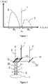
- the figure 1 very schematically represents the spectral distribution of the intensity of different measurement and display beams.
- the excitation laser beam has a wavelength ⁇ 0 and a spectral band B 0 centered on the wavelength ⁇ 0 , the spectral band B 0 being very narrow.
- the excitation beam (1) generates by Raman scattering on a sample a Raman scattering beam whose lines are located in a spectral band B R represented schematically by the curve (3) on the figure 1 .
- One aspect of the invention consists in using a display beam having a spectral band B V distinct from the spectral band B 0 of the laser and from the spectral band B R which it is sought to measure.
- the figure 2 schematically represents an exemplary embodiment of a device according to an embodiment of the invention so as to illustrate the path of the different beams.
- the device of the figure 2 makes it possible to superimpose an incident laser beam and an incident lighting beam and simultaneously to separate the beam diffused by the sample (7) and collected by the objective (6) according to its different spectral components, more precisely according to the spectral bands B 0 , B V and B R.
- the beam (21) is a backscattering beam from the excitation laser having a spectral band B 0 (Rayleigh scattering).
- the beam (3) is the Raman scattering beam which has a spectral component B R.
- the viewing beam (22) is a Rayleigh backscattering beam of the illumination beam (2) which has a spectral component B v .
- the filter (12) transmits the Raman scattering beam (3) and reflects the Rayleigh scattering beams (21) and (22).
- the filter (13) transmits the viewing beam (22) scattered by the sample (7) and reflects the Rayleigh scattering beam at the wavelength of the laser.
- a splitter plate (16) transmits the viewing beam (22) diffused by the sample, for example in the direction of a viewing camera (not shown).
- the Raman beam (3) can be transmitted in the direction of a Raman spectrometer in order to provide the measurement of the Raman lines in the spectral band B R.
- the device of the figure 2 thus makes it possible to visualize the sample thanks to the visualization beam (22) and simultaneously to perform a Raman measurement thanks to the Raman scattering beam (3) which is separated from the Rayleigh diffusions of the laser beam and of the illumination beam.
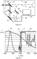
- the figure 3 shows a device according to a preferred embodiment of the invention.
- the device of the figure 3 can be coupled directly to a Raman spectrometer or deported relative to the Raman spectrometer to be placed as close as possible to the sample, the device then being connected to a Raman spectrometer by optical fibers.
- the housing (20) includes an input (10) for coupling an exciting laser beam and directing it to a first deflection mirror (14).
- the laser beam (1) is transmitted by the filter (13) and then reflected by the filter (12) to be transmitted towards the sample through the optical focusing component (15).
- the housing (20) comprises a display source (11) which is for example a green LED emitting in a wavelength range between 500 and 550 nm.
- the source of visualization (11) generates a visualization beam (2) which is directed towards a splitter plate (16), then transmitted in the direction of the filter (13).
- the filter (13) reflects the beam (2) towards the filter (12) which also reflects the viewing beam (2) towards the sample, so as to superimpose it on the laser excitation beam (1).
- the scattering beam collected through the window (15) comprises a Raman scattering beam (3) which is transmitted through the filter (12) towards a module (18) which can be either a Raman spectrometer or a connector of fibers so as to transmit the Raman beam (3) to a remote Raman spectrometer.
- the beam scattered by the sample at the wavelength ⁇ 0 of the laser is reflected by the filter (12), transmitted by the filter (13) and redirected to the input / output (10).
- the collected beam also comprises a component in the spectral band B V of the display source.
- the backscattered viewing beam (22) is reflected by the filter (12) and by the filter (13) then transmitted by the splitter plate (16). This viewing beam (22) is directed towards a viewing camera (17).
- a prototype of a remote fiber probe, based on the diagram of the figure 3 was carried out for an excitation laser having a wavelength ⁇ 0 of 660nm, but this principle can be applied to any device.
- the filter (12) reflects the laser (660nm), the low wavelength illumination (less than 660nm) and the light reflected by the sample.
- the filter (12) transmits the Raman scattering beam for wavelengths from 665 nm, the Raman range extending in wavenumber between 400 and 3500 cm -1 .
- the filter (13) transmits the excitation laser at 660nm and reflects the illumination beam at low wavelength.
- the splitter blade (16) makes it possible to separate the illumination beam (2) which goes from the illumination source to the sample from the viewing beam (22) which goes from the sample to a viewing camera.
- the device of the figure 3 is compatible with a confocal video system.
- the excitation laser is coupled to the input connector (10) via an optical fiber with a core diameter of 5-6 microns.
- the probe is connected to a Raman spectrometer via optical fiber having a core diameter of about 100 microns.
- the light source is a green LED with a 15 ° opening and a light intensity of approximately 6800 mcd.
- the figure 4 schematically represents the relative spectral response of the different sources and filters used.
- the laser beam (1) has a wavelength ⁇ 0 and a very narrow spectral band B 0.
- the curve (2) corresponding to the spectral emission curve of the display source (11) is observed.
- the spectral detection curve of the viewing camera (17) has a very broad spectrum with maximum sensitivity around the spectral band B V of the viewing source.
- the filter (12) is a high pass filter having a cut-off wavelength located just above the wavelength ⁇ 0 of the laser while the filter (13) passes the wavelength of the laser and reflects the wavelengths in the viewing spectral band B V.
- the figure 5 schematically represents a first case, not forming part of the invention, according to which the excitation wavelength ⁇ 0 defines a spectral band B 0 .
- the excitation wavelength ⁇ 0 defines a spectral band B 0 .
- the spectral viewing band B V is located at wavelengths less than the excitation wavelength ⁇ 0 .
- the laser can have a wavelength of 660 nm and visualization can be done in the blue-green-yellow region of the visible spectrum.
- the excitation laser beam (1) is shown in solid line and the Raman scattering beam (3) Stokes in dash-dot line.
- a common dashed line (2) shows the illumination beam incident on the sample and the display beam diffused by the sample, which are superimposed on the outward and return path up to a separator blade (16) not shown.
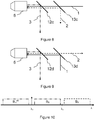
- the figure 6 shows a first embodiment, not forming part of the invention, using the distribution of the spectral bands of the figure 5 .
- the laser excitation beam (1) is transmitted by a filter (13a) and then reflected by a filter (12a) towards a focusing objective (6).
- the viewing beam (2) is reflected by the filter (13a) then by the filter (12a) towards the objective (6).
- the collected beam comprises the Raman scattering beam (3) which is transmitted by the filter (12a).
- the collected scattered beam also comprises a viewing beam which is reflected by the filter (12a) then by the filter (13a).
- the filter (13a) is a high-pass or band-pass filter having a cut-off wavelength situated between the viewing band B V and the band B 0 of the laser.
- the filter (12a) is a high pass filter having a cut-off wavelength located between the wavelength ⁇ 0 of the laser and the Raman scattering band B R.
- the filter (13a) therefore serves to superimpose the excitation laser beam and the illumination beam in the direction of the sample and on the scattering beam to separate the viewing beam from the backscatter at the wavelength of the laser.
- the filter (12a) serves to separate on the one hand the beam from the Raman scattering (3) and on the other hand the spectral components of the scattering beam in the spectral band B 0 of the laser and in the spectral band B V of the beam visualization.
- the figure 7 shows a second embodiment of a device, not forming part of the invention, still using the spectral distribution according to the diagram of the figure 5 .
- the laser beam (1) is first reflected by a filter (13b) before being reflected on a filter (12b).
- the lighting beam (2) is transmitted by the filter (13b) before being reflected by the filter (12b).
- the scattered and collected beam is directed towards the first filter (12b) which transmits the Raman scattering beam (3) and reflects the components of the scattered beam in the spectral band B 0 of the laser and in the spectral band B V of the viewing beam 2.
- the filter (13b) separates the scattered viewing beam from the scattered beam at the wavelength of the laser.
- the filter (12b) is a high pass filter having a cutoff wavelength located between the wavelength ⁇ 0 of the laser and the Raman spectral band B R.
- the filter (13b) is a low-pass or band-cut filter having a cut-off wavelength located between the viewing spectral band B V and the spectral band B 0 which transmits the beam in the spectral band B V and reflects a beam having wavelengths in the spectral band B 0 .
- the figure 8 schematically shows a third embodiment, not forming part of the invention, based on the spectral distribution of the diagram of the figure 5 .
- the excitation laser beam (1) is transmitted by a filter (13c) then by a filter (12c) towards the objective (6).
- the lighting beam (2) is reflected on the filter (13c) and transmitted by the filter (12c).
- the Raman scattering beam (3) is reflected by the filter (12c).
- the scattering beam (2) in the spectral viewing band B V is transmitted by the filter (12c) and reflected by the filter (13c).
- the filter (13c) is a high-pass or band-pass filter having a cut-off wavelength situated between the spectral band B V and the band B 0 which transmits the band B 0 and reflects the band B V.
- the filter (12c) is a low-pass filter having a cut-off wavelength between the band B 0 , and the Raman band B R which transmits the wavelength of the spectral band B V and of the spectral band B 0 and reflects a beam having wavelengths in the spectral band B R.
- the figure 9 shows a fourth embodiment, not forming part of the invention, according to the spectral distribution of the diagram of the figure 5 .
- the device includes a filter (12d), a filter (13d) and an objective (6).
- the excitation laser beam (1) is reflected on the filter (13d) then transmitted by the filter (12d) towards the objective (6).
- the lighting and visualization beam (2) is transmitted by the filter (13d) and the filter (12d).
- the Raman scattering beam (3) collected is reflected by the filter (12d) while the scattering beam in the spectral band B V of the viewing beam is transmitted by the filter (12d) and by said filter (13d).
- the filter (13d) is a low-pass or band-cut filter having a cut-off wavelength situated between the viewing band B V and the band B 0 of the laser which transmits the viewing band B V and reflects the band B 0 .
- the filter (12d) is a low pass filter which transmits the bands B 0 and B V and reflects the Raman diffusion band B R.
- the filter (12d) has a cut-off wavelength between the band B 0 and the band B R.
- the figure 10 represents a case of distribution of the spectral bands according to the invention: the laser excitation spectral band, the Raman Stokes measurement bands (band spectral B R ) and anti-Stokes Raman (spectral band B R aS ) and the visualization band Bv.
- the wavelength ⁇ 0 of the excitation laser is located at 473nm while the viewing spectral band B V is located in the yellow-red part of the visible spectrum, for example in a range of wavelengths above 600 nm.
- the Raman Stokes band is located at wavelengths greater than the laser excitation wavelength ⁇ 0 and less than a wavelength ⁇ 1 which is itself less than the viewing band B V.
- the Anti-Stokes Raman scattering band is located at wavelengths less than the laser excitation wavelength ⁇ 0.
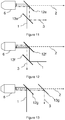
- the figure 11 shows a first embodiment according to the spectral distribution of the figure 10 .
- the excitation laser beam (1) is transmitted by a filter (13e) and reflected by a filter (12e).
- the lighting and display beam (2) is transmitted by the filter (12e) which retransmits the beam diffused in the display band B V.
- the filter (12e) reflects the Raman scattering beam (3).
- the filter (13e) reflects the Raman scattering beam (3).
- the filter (13e) is a low-pass filter which transmits the band B 0 and reflects the band B R which therefore has a cut-off wavelength situated between the band B 0 and the band B R.
- the filter (12e) is a high pass filter which transmits the viewing band B V and reflects the spectral bands B 0 and B R.
- the filter (12e) is a filter having a cut-off wavelength between the Raman band B R and the visualization band B V.
- the filter (13e) is a bandpass filter which transmits the B 0 band and reflects the Raman B R Stokes bands and the Raman Anti-Stokes band B R aS
- the figure 12 schematically represents a second embodiment based on the spectral distribution of the diagram of the figure 10 .
- the device of the figure 12 comprises a filter (13f) which reflects the excitation beam to the laser (1).
- the illumination and visualization beam (2) is transmitted by the filter (12f) which reflects the scattered Raman beam (3) and transmits the part of the scattered beam in the visualization band B V.
- the filter (13f) separates the Raman beam (3) from the Rayleigh scattered beam at the wavelength of the laser.
- the filter (12f) is a high pass filter which transmits the viewing band B V and reflects the spectral bands B 0 and B R and has a cut-off wavelength between B R and B V.
- the filter (13f) transmits the Raman scattering spectral band B R and reflects the band B 0 of the laser.
- the filter (13f) is a high-pass filter having a cut-off wavelength situated between the spectral bands B 0 and B R.
- the filter (13f) is a notch filter which reflects the spectral band B 0 of the excitation beam and transmits the Raman scattering bands B R Stokes and Anti-Stokes B R aS .
- the figure 13 shows a third embodiment according to the spectral distribution of the figure 10 .
- the filter (12g) superimposes the excitation laser beam (1) and the illumination and visualization beam (2) by reflecting the laser beam (1) and transmitting the illumination and visualization beam (2) in the spectral band B V.
- the filter (12g) transmits the viewing beam in the spectral band B V and the Raman scattering beam (3) and reflects the Rayleigh scattering beam in the spectral band B 0 .
- the filter (13g) transmits the viewing beam (2) in the spectral band B V and reflects the Raman scattering beam (3).
- the filter (13g) is a high pass filter having a cutoff wavelength located between the Raman spectral band B R and the visualization band B V so as to transmit the visualization band B V and to reflect the spectral band B R.
- the filter (12g) is a high-pass filter which transmits the spectral band B R , the spectral band B V and reflects the spectral band B 0 .
- the filter (12g) is a notch filter which reflects the spectral band B 0 , transmits the Raman anti-Stokes spectral band, the Raman spectral band Stokes and the viewing spectral band B V.
- the figure 14 shows a fourth embodiment according to the spectral distribution of the figure 10 .
- the filter (12h) makes it possible to superimpose the excitation laser beam (1) and the illumination and display beam (2) in the direction of the sample.
- the filter (12h) reflects the signal scattered by Rayleigh scattering in the spectral band B 0 , transmits the viewing beam in the spectral band B V and the Rayleigh scattering beam in the spectral band B R or B R as .
- the filter (13h) is a low pass filter which transmits the Raman diffusion band B R and reflects the spectral viewing band B V.
- the filter (12h) is a high-pass filter having a cut-off wavelength between the spectral band B 0 and the spectral band B R so as to reflect the band spectral B 0 and to transmit the spectral bands B R and B V.
- the filter (12h) is a notch filter which reflects the spectral band B 0 and transmits the spectral bands B R Stokes B R aS anti- Stokes as well as the lines of the spectral band of visualization B V.
- the figure 15 represents a fifth embodiment for a measurement of the Raman Stokes lines according to the distribution of the figure 10 .
- the filter (13i) makes it possible to superimpose the excitation laser beam (1) and the illumination and display beam (2) in the direction of the object 6 and the sample.
- the filter (12i) transmits both the laser excitation beam (1) and the visualization beam (2).
- the filter (12i) separates the Raman scattering beam (3) from the viewing beam (2).
- the filter (13i) reflects the viewing beam (2) and transmits the Rayleigh scattered beam at the wavelength of the laser.
- the filter (13i) is a low pass filter which transmits the band B 0 and reflects the band Bv.
- the filter (12i) is a wide notch filter which transmits the band B 0 , reflects the Raman band B R and transmits the visualization band B V.
- the figure 16 represents another embodiment for the measurement of Raman Stokes lines alone, according to the spectral distribution of the fig. 10 .
- the device of the figure 16 comprises a filter (13j) which makes it possible to superimpose the excitation laser beam (1) and the visualization beam by reflecting the laser beam in the spectral band B 0 and by transmitting the visualization beam in the spectral band B V.
- the filter 12j simultaneously transmits the excitation and lighting and visualization beam (2).
- the filter (12j) reflects the Raman scattering beam (3) in the spectral band B R and transmits the Rayleigh scattering beam at the wavelength of the laser in the spectral band B 0 as well as the visualization beam (2) scattered by the sample in the spectral band B V.
- the filter (13j) separates the viewing beam (2) in the spectral band B V from the Rayleigh scattering beam in the spectral band B 0 .
- the filter (12j) is a wide notch filter which transmits the spectral band B 0 reflects the Raman spectral band B R and transmits the visualization band B V.
- the filter (13j) is a high-pass filter having a cut-off wavelength between the spectral band B 0 and the display band B V.
- the figure 17 represents another embodiment related to the spectral distribution of the diagram of the figure 10 .
- the device comprises a filter (12k) which makes it possible to superimpose the excitation laser beam (1) and the visualization beam (2) by transmitting the beam in the spectral band B 0 and by reflecting the beam in the spectral band B V .
- the collected scattering beam comprises a spectral component in the viewing band B V which is reflected by the filter (12k).
- the filter (12k) is a low pass filter which transmits the spectral band B 0 and the Raman scattering spectral band B R and which reflects the spectral band B V.
- the filter (13k) transmits the Raman scattering beam (3) in the Raman spectral band and reflects the Rayleigh scattering beam in the spectral band B 0 .
- the filter (13k) can be a high-pass filter having a cut-off wavelength situated between the spectral band B 0 and the Raman Stokes spectral band B R.
- the filter (13k) is a notch filter which reflects the spectral band B 0 and transmits the Raman Stokes B R and Anti-Stokes B R aS scattering spectral bands.
- the figure 18 shows another embodiment for a spectral distribution following the path of the figure 10 .
- the device comprises a filter (12l) which makes it possible to superimpose the laser excitation beam and the visualization beam (2) by transmitting the laser excitation beam (1) and by reflecting the visualization beam (2).
- the filter (12l) makes it possible to extract the viewing beam in the spectral viewing band B V and transmits the Raman scattering signal in the band B R as well as the Rayleigh scattering signal in the spectral band B 0 .
- the filter (12l) is a low pass filter which transmits the band B 0 and the band B R and reflects the band B V and therefore has a cut-off wavelength located above the wavelength ⁇ 0 between the Raman band B R and the spectral band B V for visualization.
- the filter (13l) reflects the Raman scattering signal and transmits the Rayleigh scattering signal in the spectral band B 0 .
- the filter (13l) is a low-pass filter which transmits the spectral band B 0 and reflects the Raman spectral band B R.
- the filter (13l) is a bandpass filter which transmits only the spectral band B 0 and which reflects the Raman Stokes B R scattering spectral bands. and Anti-Stokes B R aS
- the figure 19 represents another case of spectral distribution of the laser excitation display bands in the case where the anti-Stokes and Stokes Raman lines are measured; this case not forming part of the invention.
- the viewing band B V is here located at wavelengths less than the scattering band of Anti-Stokes B R aS Raman lines.
- the filter (12m) makes it possible to superimpose the excitation laser beam (1) and the visualization beam (2).
- the excitation beam (1) being transmitted and the viewing beam (2) being reflected by the filter (12m).
- the filter (12m) makes it possible to extract a scattered beam in the viewing band B v and to transmit the Raman scattering beam (3) as well as the Rayleigh scattering beam in the spectral band B 0 .
- the filter (12m) is a high pass filter having a cutoff wavelength between the viewing band B V and the anti-Stokes Raman scattering band.
- the filter (12m) transmits the signals in the bands B 0 , B R aS and possibly B R Stokes and reflects the viewing band B V.
- the filter (13m) is a high-pass filter which transmits the spectral band B 0 and reflects the spectral band of anti-Stokes Raman scattering.
- the filter (13m) is a bandpass filter which transmits the spectral band B 0 and reflects the Raman Stokes and anti-Stokes scattering bands.
- the figure 21 shows another embodiment, not forming part of the invention, corresponding to the distribution shown schematically on the figure 19 .
- the device includes a filter (12n) and a filter (13n).
- the filter (12n) makes it possible to superimpose the excitation laser beam (1) and the visualization beam (2) by reflecting the beam (2) and transmitting the beam (1).
- the filter (12n) makes it possible to extract the scattered beam in the viewing band B V and to transmit the scattered beams in the B 0 band as well as in the Raman scattering band.
- the filter (13n) makes it possible to separate the beam scattered in the spectral band B 0 of the excitation laser of the Raman scattering beam (3).
- the filter (12n) is a high-pass filter which transmits the spectral bands B 0 and B R aS (Raman anti-Stokes) and which reflects the spectral viewing band B V
- the filter (13n) is a low-pass filter which transmits the anti-Stokes diffusion band B R aS and reflects the spectral band B 0
- the filter (13n) is a notch filter which reflects the spectral band B 0 and transmits the Raman Stokes B R scattering bands and Anti-Stokes B R aS .
- the figure 22 shows yet another embodiment, not forming part of the invention, according to the diagram of figure 19 in which a filter (12o) makes it possible to superimpose the excitation laser beam (1) and the illumination and visualization beam (2) by reflecting the laser beam (1) and transmitting the illumination and visualization beam (2) in the spectral band B V.
- the filter (12o) transmits the scattered beam in the viewing band B V and reflects the scattered beam in the Raman scattering bands and in the Rayleigh scattering band B 0 .
- the filter (12o) is a low-pass filter which transmits the viewing band B V and reflects the B R Anti-Stokes diffusion bands, the B 0 band and possibly the Raman stokes diffusion band.
- the filter (13o) transmits the beam scattered in the Raman spectral bands and reflects the Rayleigh beam scattered in the spectral band B 0 of the laser.
- the filter (13o) is a low-pass filter which transmits the anti-Stokes Raman diffusion band and reflects the spectral band B 0 .
- the filter (13o) is a notch filter which reflects the spectral band B 0 and transmits the Raman stokes B R and Anti-Stokes scattering bands B R aS .
- the figure 23 describes a fourth embodiment, not forming part of the invention, in connection with the spectral distribution of the figure 19 .
- the filter (12p) makes it possible to superimpose the excitation laser beam (1) and the illumination and display beam (2) by reflecting the laser beam and transmitting the illumination and visualization beam in the spectral band B V.
- the filter (12p) transmits the beam display (2) in the spectral band B V and reflects the Raman scattering signals in the spectral band B R and the beam scattered by Rayleigh scattering in the spectral band B 0
- the filter (12p) thus makes it possible to extract the beam from visualization (2).
- the filter (13p) makes it possible to separate the Rayleigh scattering beam in the spectral band B 0 and the Raman scattering beam (3).
- the filter (12p) is a low pass filter which transmits the viewing band B V reflects the Raman Anti-Stokes scattering band and the spectral band B 0 . If one wishes to measure only the Anti-Stokes lines, the filter (13p) is a high-pass filter which transmits the spectral band B 0 and reflects the Raman Anti-Stokes B R aS scattering band. where one wishes to simultaneously measure the Stokes and anti-Stokes lines, the filter (13p) is a bandpass filter which transmits the spectral band B 0 and reflects the Raman stokes B R and anti-Stokes B R aS scattering band
- the figure 24 represents a fourth case, not forming part of the invention, where it is desired to measure only the scattering of the anti-Stokes Raman lines and where the spectral viewing band B V is located above the B 0 band of the laser of excitement.
- the figures 25 to 28 show different embodiments, not forming part of the invention, depending on the spectral distribution of the figure 24 .
- a filter (13q) makes it possible to superimpose the excitation beam which is reflected by the filter (13q) and a display beam (2) transmitted by this filter.
- a filter (12q) reflects the scattered beam in the anti-Stokes Raman band and transmits the scattered beam in the viewing band and in the spectral band B 0 .
- the filter (13q) makes it possible to transmit the signal diffused in the viewing band B V and to reflect the Rayleigh scattering beam in the spectral band B 0 .
- the filter (12q) is a high-pass filter having a cut-off wavelength between the Raman Anti-Stokes spectral band B R aS and the spectral band B 0 which therefore transmits the spectral bands B 0 and B V of visualization and reflects the Raman Anti-Stokes spectral band.
- the filter (13q) is a high-pass or band-cut filter having a cut-off wavelength situated between the viewing band and the band B 0 which transmits the spectral band B V and reflects the spectral band B 0 .
- the figure 26 describes a second embodiment, not forming part of the invention, in connection with the spectral distribution of the figure 24 .
- the filter (13r) makes it possible to superimpose the excitation laser beam (1) transmitted and the illumination and display beam (2) which is reflected by the filter (13r).
- the filter (12r) transmits the combined excitation and visualization beam.
- the filter (12r) reflects the Raman Anti-Stokes scattering beam (3) and transmits the scattered beams in the spectral band B 0 and in the viewing band B v .
- the filter (13r) separates the beam scattered in the viewing band B v and the beam scattered in band B 0 .
- the filter (12r) is a high pass filter having a cutoff wavelength between the Raman Anti-Stokes scattering and the B 0 band.
- the filter (12r) therefore reflects the Raman Anti-Stokes band and transmits the spectral bands B 0 and B V.
- the filter (13r) is a low-pass or band-pass filter which transmits the spectral band B 0 and reflects the visualization band B V.
- the figure 27 describes a third embodiment, not forming part of the invention, in connection with the spectral distribution of the figure 24 .
- the filter (12s) makes it possible to superimpose the reflected laser excitation beam (1) and the transmitted illumination and display beam (2). On the collected scattered beam, the filter (12s) transmits the scattered beam in the viewing band B V and reflects the scattered beam in the spectral band B 0 and in the anti-Stokes B R aS Raman scattering band.
- the filter (12s) is a high-pass filter, the cut-off wavelength of which is situated between the spectral band B 0 and the display band B V.
- the filter (13s) reflects the Raman scattering beam (3) in the Anti-Stokes scattering band B R aS and transmits the Rayleigh scattering beam in the spectral band B 0 .
- the filter (13s) is a high-pass or band-pass filter whose cut-off wavelength is located between the Raman Anti-Stokes diffusion band and the B 0 band so as to transmit the B 0 band and reflects the Raman Anti-Stokes broadcast band.
- the filter (12t) makes it possible to superimpose the excitation laser beam (1) and the visualization beam (2).
- the filter (12t) reflects the scattered beam in the anti-Stokes Raman scattering band and in the spectral band B 0 and transmits the scattered beam in the viewing band B V.
- the filter (13t) transmits the scattered beam in the anti-Stokes Raman scattering band and reflects the scattered beam in the spectral band B 0 .
- the filter (12t) is a high-pass filter having a cut-off wavelength situated between the spectral band B 0 and the visualization band B V.
- the filter (12t) therefore transmits the display band B v and reflects the spectral band B 0 as well as the anti-Stokes Raman scattering band.
- the filter (13t) is a low-pass or band-cut filter which transmits the anti-Stokes Raman scattering band reflects the band scattered in the spectral band B 0 .
- the different variant embodiments described in connection with the figures 2 , 6-8 , 11-18 , 20-23 and 25-28 all relate to a backscatter configuration.
- the same principle also applies to other Raman scattering configurations (forward scattering, or lateral scattering), in which case the means for superimposing the laser excitation beam and the illumination beam are separate from the means for filtering the scattering beam.
- the principle the use of disjoint spectral ranges nevertheless applies in the same way.
- Those skilled in the art will therefore adapt the device and the method of the invention to the different experimental configurations of Raman spectrometry.
- the same principle is used with several excitation laser wavelengths at the same time and multi-cut filters to separate the different excitation spectral bands, the viewing spectral band and the bands.
- Raman spectral values associated respectively with each of the excitation laser wavelengths.
- a notch filter simultaneously performs a high-pass filter function and a low-pass filter function. Therefore, it is equivalent to replacing a high pass and low pass filter with a notch filter.
- the filters can be produced by dielectric stacks or by the VBG (Volume Bragg Grating) technique.
- VBG Volume Bragg Grating
- the invention discloses an arrangement of filters without moving parts which makes it possible to carry out a Raman measurement and to visualize the sample, the visualization and the measurement being able to be simultaneous.
- the display device of the invention is compact and has a size reduced by half compared to a display system of the prior art based on an optical component which can be retracted onto the optical path.
- the device and the method are easy to use, since they do not require a motor or moving parts.
- the absence of a moving part also makes the device robust.
- the device hardly induces any losses on the Raman signal (extremely minimal losses of a few percent).
- the extinction ratio of the filters can be chosen so that a very small part of the beam coming from the Rayleigh scattering of the excitation laser beam is transmitted towards the sample display system.
- the display system advantageously makes it possible to simultaneously visualize the sample and the position of the excitation laser beam on the sample.
- the Rayleigh scattering beam being very attenuated, it does not present any risk of saturation of the display sensor, for example of a CCD camera.
- the device of the invention simultaneously allows the visualization of a sample and a Raman measurement of this sample without inducing high optical intensity losses.
- this device is composed of fixed elements.
- the devices of the prior art involve either a sequential visualization and a measurement, or a concomitant visualization of a measurement, but with high losses in optical intensity.
- a device of the prior art based on one or two beam splitters (of the splitter blade or splitter cube type) has a limited efficiency between 6 and 25%.
- the efficiency (in optical transmission) of a device of the invention composed of two filters is greater than or equal to 90%, or even to 95%.
- the device of the invention has the advantage of considerably reducing optical losses, and of allowing the measurement of a Raman signal which is always very weak.
Landscapes
- Physics & Mathematics (AREA)
- Spectroscopy & Molecular Physics (AREA)
- General Physics & Mathematics (AREA)
- Health & Medical Sciences (AREA)
- Biochemistry (AREA)
- Analytical Chemistry (AREA)
- Chemical & Material Sciences (AREA)
- General Health & Medical Sciences (AREA)
- Life Sciences & Earth Sciences (AREA)
- Immunology (AREA)
- Pathology (AREA)
- Nuclear Medicine, Radiotherapy & Molecular Imaging (AREA)
- Investigating, Analyzing Materials By Fluorescence Or Luminescence (AREA)
Description
- La présente invention concerne le domaine de la spectrométrie Raman.
Plus précisément, l'invention concerne un dispositif et un procédé de visualisation pour spectromètre Raman. - Depuis l'arrivée des sources laser, la spectroscopie Raman a connu un essor formidable et trouve aujourd'hui des applications dans des domaines très variés, allant de la recherche fondamentale à des applications industrielles de contrôle de procédé.
- La spectroscopie Raman est basée sur la mesure de transitions entre des états vibrationnels d'une structure polyatomique, moléculaire ou ionique (et sur les états de rotations dans le cas de gaz), quel que soit l'état physique de l'échantillon (gaz, liquide, solide amorphe ou cristallin). Un échantillon éclairé par une source de lumière monochromatique (un laser) diffuse de la lumière qui n'est plus monochromatique mais présente des bandes de diffusion à différentes fréquences. Ainsi, le spectre obtenu est composé de trois sources de diffusion : les bandes Rayleigh (diffusion élastique), Stokes et Anti-Stokes (diffusion inélastique). Les fréquences Raman sont spécifiques pour chaque échantillon et sont indépendantes de la fréquence du laser. La spectroscopie Raman permet ainsi une analyse chimique non destructive de solides, liquides, poudres ou de gaz.
- Plus récemment, la miniaturisation des composants optiques a permis de coupler la spectrométrie Raman à la microscopie optique standard pour permettre l'analyse d'échantillons avec une résolution spatiale micrométrique. Le faisceau laser d'excitation est généralement focalisé par un objectif ou une lentille optique. Différents appareils de spectrométrie Raman disposent d'un système de visualisation qui permet d'éclairer l'échantillon et de former une image de l'échantillon sur un écran. Un système de visualisation est généralement basé sur l'utilisation d'une source de lumière blanche (lampe classique), d'une caméra de visualisation et d'un composant optique escamotable, tel qu'une lame semi-transparente, sur le chemin optique de l'instrument de mesure. La mise en place du dispositif de visualisation permet d'effectuer la mise au point sur l'échantillon avant la mesure, par exemple grâce à un système autofocus. Dans un tel dispositif, pour effectuer une mesure de l'échantillon par spectrométrie Raman, il faut retirer le dispositif d'éclairage et de visualisation du chemin optique, par exemple en rétractant la lame semi-transparente hors du chemin optique. Cependant, un tel dispositif peut présenter des difficultés de manipulation. En effet, l'utilisation d'un composant optique escamotable suppose un mouvement mécanique qui entraîne un risque de bougé. De plus, le manque de reproductibilité du mouvement opto-mécanique peut produire une mise au point différente de l'échantillon vu par le système de visualisation et par le système de mesure Raman.
- Dans certaines applications, il est souhaitable d'effectuer un suivi de l'échantillon en fonction du temps et il apparaît utile de pouvoir visualiser l'échantillon pendant une série de mesures Raman. Dans certaines applications particulières, il peut même être nécessaire d'effectuer ou d'ajuster la mise au point sur l'échantillon simultanément avec la mesure. Toutefois, l'utilisation d'un dispositif d'éclairage pendant la mesure Raman risque de perturber la mesure des signaux Raman. Premièrement, le laser d'excitation est susceptible de générer de la lumière parasite en direction de la caméra de visualisation, qui risque de saturer le capteur de la caméra et d'empêcher une visualisation correcte de l'échantillon. De plus, la présence permanente d'un composant optique supplémentaire, tel qu'une lame semi-transparente, sur le chemin optique entraîne nécessairement une baisse du signal Raman détecté. Enfin, la source d'éclairement est susceptible de générer de la lumière parasite par diffusion non seulement sur l'échantillon mais aussi sur les composants internes de l'appareil et ainsi de perturber la mesure des signaux Raman. Or la difficulté de mesure des signaux Raman provient essentiellement de la très faible intensité de la diffusion Raman comparée à l'intensité de la diffusion Rayleigh. Il n'est donc pas possible, avec les systèmes actuels, d'effectuer simultanément une mesure Raman et la visualisation d'un échantillon. Les documents de brevet
WO2008052221 ,WO2004081549 etWO2010/024397 proposent de combiner un système de mesure de spectrométrie Raman ayant une source d'excitation dans le domaine proche infra-rouge avec un système d'imagerie basé sur un éclairage en lumière blanche. - Un des buts de l'invention est de fournir un dispositif et un procédé de visualisation et de spectrométrie Raman.
- Un but de l'invention est de fournir un dispositif et un procédé permettant simultanément la visualisation et la mesure par spectrométrie Raman d'un échantillon. La présente invention a pour but de remédier à ces inconvénients et concerne plus particulièrement un dispositif optique de spectrométrie Raman et de visualisation d'un échantillon selon la revendication 1.
- Selon différents aspects particuliers l'invention, lesdits moyens optiques de superposition comprennent :
- un filtre optique apte à réfléchir ledit faisceau laser d'excitation de bande spectrale B0 et à transmettre ledit faisceau de visualisation de bande spectrale BV ;
- un filtre optique apte à transmettre ledit faisceau laser d'excitation de bande spectrale B0 et à réfléchir ledit faisceau de visualisation de bande spectrale BV;
- ledit premier moyen de filtrage comprend un filtre optique apte à réfléchir ledit premier faisceau secondaire et à transmettre ledit deuxième faisceau secondaire ;
- ledit premier moyen de filtrage comprend un filtre optique apte à transmettre ledit premier faisceau secondaire et à réfléchir ledit deuxième faisceau secondaire ;
- ledit deuxième moyen de filtrage comprend un filtre optique apte à réfléchir ledit premier faisceau tertiaire et à transmettre ledit deuxième faisceau tertiaire ;
- ledit deuxième moyen de filtrage comprend un filtre optique apte à transmettre ledit premier faisceau tertiaire et à réfléchir ledit deuxième faisceau tertiaire
- ledit filtre optique est choisi parmi un filtre passe-haut, passe-bas, passe-bande ou coupe-bande ;
- Selon des aspects particuliers le dispositif de l'invention comporte en outre :
- des moyens de réglage d'autofocus, et/ou
- des moyens de stabilisation d'image couplés à des moyens de déplacement relatif de l'objet par rapport au faisceau d'excitation laser.
- L'invention concerne aussi un procédé de spectrométrie Raman selon la revendication 11.
- Cette description donnée à titre d'exemple non limitatif fera mieux comprendre comment l'invention peut être réalisée en référence aux dessins annexés sur lesquels :
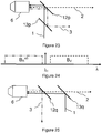
- la
figure 1 représente schématiquement une répartition spectrale de l'intensité du faisceau laser d'excitation, du faisceau d'éclairage et de visualisation et du faisceau de diffusion Raman ; - la
figure 2 représente schématiquement un exemple de réalisation d'un dispositif de l'invention illustrant le chemin optique des différents faisceaux incidents et diffusés ; - La
figure 3 représente un dispositif selon un mode de réalisation préféré de l'invention ; - la
figure 4 représente schématiquement les spectres en intensité des composants utilisés dans le dispositif de lafigure 3 ; - la
figure 5 représente un premier cas de répartition des bandes spectrales; ce cas ne faisant pas partie de l'invention; - les
figures 6 à 9 représentent différents modes de réalisation, ne faisant pas partie de l'invention, utilisant la répartition des bandes spectrales de lafigure 5 ; - la
figure 10 représente un deuxième cas de répartition des bandes spectrales, selon l'invention; - les
figures 11 à 18 représentent différents modes de réalisation de l'invention utilisant la répartition des bandes spectrales de lafigure 10 ; - la
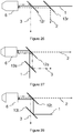
figure 19 représente un troisième cas de répartition des bandes spectrales; ce cas ne faisant pas partie de l'invention; - les
figures 20 à 23 représentent différents modes de réalisation, ne faisant pas partie de l'invention, utilisant la répartition des bandes spectrales de lafigure 19 ; - la
figure 24 représente un quatrième cas de répartition des bandes spectrales; ce cas ne faisant pas partie de l'invention; - les
figures 25 à 28 représentent différents modes de réalisation, ne faisant pas partie de l'invention, utilisant la répartition des bandes spectrales de lafigure 24 . - L'invention propose un arrangement de filtres permettant de faire du Raman et la visualisation de l'échantillon sans parties mobiles et en simultané.
- L'idée est d'utiliser une gamme spectrale spécifique pour l'éclairement et la visualisation de l'échantillon, cette gamme spectrale étant disjointe de celle du laser et de la plage Raman induite.
- La
figure 1 représente très schématiquement la répartition spectrale de l'intensité de différents faisceaux de mesure et de visualisation. Le faisceau laser d'excitation a une longueur d'onde λ0 et une bande spectrale B0 centrée sur la longueur d'onde λ0, la bande spectrale B0 étant très étroite. Le faisceau d'excitation (1) génère par diffusion Raman sur un échantillon un faisceau de diffusion Raman dont les raies sont situées dans une bande spectrale BR représentée schématiquement par la courbe (3) sur lafigure 1 . - Un aspect de l'invention consiste à utiliser un faisceau de visualisation ayant une bande spectrale BV distincte de la bande spectrale B0 du laser et de la bande spectrale BR que l'on cherche à mesurer.
- La
figure 2 représente schématiquement un exemple de réalisation d'un dispositif selon un mode de réalisation de l'invention de manière à illustrer le chemin des différents faisceaux. Le dispositif de lafigure 2 permet de superposer un faisceau incident laser et un faisceau incident d'éclairage et simultanément de séparer le faisceau diffusé par l'échantillon (7) et collecté par l'objectif (6) en fonction de ses différentes composantes spectrales, plus précisément en fonction des bandes spectrales B0, BV et BR. Le faisceau (21) est un faisceau de rétrodiffusion du laser d'excitation ayant une bande spectrale B0 (diffusion Rayleigh). Le faisceau (3) est le faisceau de diffusion Raman qui a une composante spectrale BR. Le faisceau de visualisation (22) est un faisceau de rétrodiffusion Rayleigh du faisceau d'éclairage (2) qui a une composante spectrale Bv. Le filtre (12) transmet le faisceau de diffusion Raman (3) et réfléchit les faisceaux de diffusion Rayleigh (21) et (22). Le filtre (13) transmet le faisceau de visualisation (22) diffusé par l'échantillon (7) et réfléchit le faisceau de diffusion Rayleigh à la longueur d'onde du laser. Une lame séparatrice (16) transmet le faisceau de visualisation (22) diffusé par l'échantillon par exemple en direction d'une caméra de visualisation (non représentée). Le faisceau Raman (3) peut être transmis en direction d'un spectromètre Raman afin de fournir la mesure des raies Raman dans la bande spectrale BR. Le dispositif de lafigure 2 permet ainsi de visualiser l'échantillon grâce au faisceau de visualisation (22) et simultanément d'effectuer une mesure Raman grâce au faisceau de diffusion Raman (3) qui est séparé des diffusions Rayleigh du faisceau laser et du faisceau d'éclairage. - La
figure 3 représente un dispositif selon un mode de réalisation préféré de l'invention. Le dispositif de lafigure 3 peut être couplé directement à un spectromètre Raman ou déporté par rapport au spectromètre Raman pour être disposé au plus près de l'échantillon, le dispositif étant alors relié à un spectromètre Raman par des fibres optiques. Le boîtier (20) comprend une entrée (10) pour coupler un faisceau laser d'excitation et le diriger vers un premier miroir de renvoi (14). Le faisceau laser (1) est transmis par le filtre (13) puis réfléchi par le filtre (12) pour être transmis en direction de l'échantillon à travers le composant optique de focalisation (15). Le boîtier (20) comprend une source de visualisation (11) qui est par exemple une led verte émettant dans une gamme de longueur d'onde comprise entre 500 et 550 nm. La source de visualisation (11) génère un faisceau de visualisation (2) qui est dirigé vers une lame séparatrice (16), puis transmis en direction du filtre (13). Le filtre (13) réfléchit le faisceau (2) en direction du filtre (12) qui réfléchit également le faisceau de visualisation (2) en direction de l'échantillon, de manière à le superposer au faisceau d'excitation laser (1). Le faisceau de diffusion collecté à travers le hublot (15) comprend un faisceau de diffusion Raman (3) qui est transmis par le filtre (12) en direction d'un module (18) qui peut être soit un spectromètre Raman soit un connecteur de fibres de manière à transmettre le faisceau Raman (3) vers un spectromètre Raman déporté. Le faisceau diffusé par l'échantillon à la longueur d'onde λ0 du laser est réfléchi par le filtre (12), transmis par le filtre (13) et redirigé vers l'entrée/sortie (10). Le faisceau collecté comprend également une composante dans la bande spectrale BV de la source de visualisation. Le faisceau rétrodiffusé de visualisation (22) est réfléchi par le filtre (12) et par le filtre (13) puis transmis par la lame séparatrice (16). Ce faisceau de visualisation (22) est dirigé vers une caméra de visualisation (17). - Un prototype de sonde déportée fibrée, basée sur le schéma de la
figure 3 a été réalisé pour un laser d'excitation ayant une longueur d'onde λ0 de 660nm, mais ce principe peut s'appliquer à tout appareil. Le filtre (12) réfléchit le laser (660nm), l'éclairage en basse longueur d'onde (inférieure à 660 nm) et la lumière réfléchie par l'échantillon. Le filtre (12) transmet le faisceau de diffusion Raman pour des longueurs d'ondes à partir de 665 nm, la gamme Raman s'étendant en nombre d'onde entre 400 et 3500 cm-1. Le filtre (13) transmet le laser d'excitation à 660nm et réfléchit le faisceau d'éclairage à basse longueur d'onde. La lame séparatrice (16) permet de séparer le faisceau d'éclairage (2) qui va de la source d'éclairage vers l'échantillon du faisceau de visualisation (22) qui va de l'échantillon vers une caméra de visualisation. Le dispositif de lafigure 3 est compatible avec un système vidéo confocal. Le laser d'excitation est couplé au connecteur d'entrée (10) via une fibre optique de diamètre de cœur 5-6 microns. La sonde est reliée à un spectromètre Raman via fibre optique ayant un diamètre de cœur d'environ 100 microns. La source d'éclairage est une LED verte d'ouverture 15° et dont l'intensité lumineuse est environ de 6800 mcd. - La
figure 4 représente schématiquement la réponse spectrale relative des différentes sources et des filtres utilisés. Le faisceau laser (1) a une longueur d'onde λ0 et une bande spectrale B0 très étroite. On observe la courbe (2) correspondant à la courbe spectrale d'émission de la source de visualisation (11). La courbe de détection spectrale de la caméra de visualisation (17) présente un spectre très large avec une sensibilité maximum autour de la bande spectrale BV de la source de visualisation. Le filtre (12) est un filtre passe-haut ayant une longueur d'onde de coupure située juste au-dessus de la longueur d'onde λ0 du laser tandis que le filtre (13) laisse passer la longueur d'onde du laser et réfléchit les longueurs d'onde dans la bande spectrale BV de visualisation. - Les
figures 1 à 4 décrivent le principe de l'invention en lien avec un mode de réalisation particulier de l'invention. Toutefois de nombreuses variantes reposant sur le même principe sont valables et vont être développées dans les exemples détaillés dans lesfigures 5 à 28 en fonction des positions respectives des différentes bandes spectrales de visualisation BV, d'excitation laser B0 et de diffusion Raman BR. - La
figure 5 représente schématiquement un premier cas, ne faisant pas partie de l'invention, selon lequel la longueur d'onde λ0 d'excitation définit une bande spectrale B0. On cherche à mesurer des raies de diffusion Raman dans la bande spectrale BR correspondant aux raies Stokes c'est-à-dire ayant des longueurs d'onde supérieures à la longueur d'onde d'excitation du laser λ0. La bande spectrale de visualisation BV est située à des longueurs d'onde inférieures à la longueur d'onde d'excitation λ0. Par exemple, le laser peut avoir une longueur d'onde de 660 nm et la visualisation peut être effectuée dans le domaine bleu-vert-jaune du spectre visible. - Sur les
figures 6 à 9 , on a représenté le faisceau laser d'excitation (1) en trait plein et le faisceau de diffusion Raman (3) Stokes en trait tiret-point. Dans la suite du document on a représenté par une ligne commune en tirets (2) le faisceau d'éclairage incident sur l'échantillon et le faisceau de visualisation diffusé par l'échantillon, qui sont superposés sur le trajet aller et retour jusqu'à une lame séparatrice (16) non représentée. - La
figure 6 représente un premier mode de réalisation, ne faisant pas partie de l'invention, utilisant la répartition des bandes spectrales de lafigure 5 . Le faisceau d'excitation laser (1) est transmis par un filtre (13a) puis réfléchi par un filtre (12a) en direction d'un objectif (6) de focalisation. Le faisceau de visualisation (2) est réfléchi par le filtre (13a) puis par le filtre (12a) en direction de l'objectif (6). Le faisceau collecté comprend le faisceau de diffusion Raman (3) qui est transmis par le filtre (12a). Le faisceau diffusé collecté comprend également un faisceau de visualisation qui est réfléchi par le filtre (12a) puis par le filtre (13a). Le filtre (13a) est un filtre passe-haut ou passe-bande ayant une longueur d'onde de coupure située entre la bande de visualisation BV et la bande B0 du laser. Le filtre (12a) est un filtre passe-haut ayant une longueur d'onde de coupure située entre la longueur d'onde λ0 du laser et la bande BR de diffusion Raman. Le filtre (13a) sert donc à superposer le faisceau d'excitation laser et le faisceau d'éclairage en direction de l'échantillon et sur le faisceau de diffusion à séparer le faisceau de visualisation de la rétrodiffusion à la longueur d'onde du laser. Le filtre (12a) sert à séparer d'une part le faisceau de la diffusion Raman (3) et d'autre part les composantes spectrales du faisceau de diffusion dans la bande spectrale B0 du laser et dans la bande spectrale BV du faisceau de visualisation. - La
figure 7 représente un deuxième mode de réalisation d'un dispositif, ne faisant pas partie de l'invention, utilisant toujours la répartition spectrale selon le schéma de lafigure 5 . A la différence de lafigure 6 , le faisceau laser (1) est premièrement réfléchi par un filtre (13b) avant d'être réfléchi sur un filtre (12b). Symétriquement le faisceau d'éclairage (2) est transmis par le filtre (13b) avant d'être réfléchi par le filtre (12b). Le faisceau diffusé et collecté est dirigé vers le premier filtre (12b) qui transmet le faisceau de diffusion Raman (3) et réfléchit les composantes du faisceau diffusé dans la bande spectrale B0 du laser et dans la bande spectrale BV du faisceau de visualisation 2. Le filtre (13b) sépare le faisceau de visualisation diffusé du faisceau diffusé à la longueur d'onde du laser. Comme dans lafigure 6 , le filtre (12b) est un filtre passe-haut ayant une longueur d'onde de coupure située entre la longueur d'onde λ0 du laser et la bande spectrale Raman BR. Le filtre (13b) est un filtre passe-bas ou coupe-bande ayant une longueur d'onde de coupure située entre la bande spectrale de visualisation BV et la bande spectrale B0 qui transmet le faisceau dans la bande spectrale BV et réfléchit un faisceau ayant des longueurs d'onde dans la bande spectrale B0. - La
figure 8 représente schématiquement un troisième mode de réalisation, ne faisant pas partie de l'invention, basé sur la répartition spectrale du schéma de lafigure 5 . Le faisceau laser d'excitation (1) est transmis par un filtre (13c) puis par un filtre (12c) en direction de l'objectif (6). Le faisceau d'éclairage (2) est réfléchi sur le filtre (13c) et transmis par le filtre (12c). Le faisceau de diffusion Raman (3) est réfléchi par le filtre (12c). Le faisceau de diffusion (2) dans la bande spectrale de visualisation BV est transmis par le filtre (12c) et réfléchi par le filtre (13c). Le filtre (13c) est un filtre passe-haut ou passe-bande ayant une longueur d'onde de coupure située entre la bande spectrale BV et la bande B0 qui transmet la bande B0 et réfléchit la bande BV. Le filtre (12c) est un filtre passe-bas ayant une longueur d'onde de coupure comprise entre la bande B0, et la bande Raman BR qui transmet la longueur d'onde de la bande spectrale BV et de la bande spectrale B0 et réfléchit un faisceau ayant des longueurs d'onde dans la bande spectrale BR. - La
figure 9 représente un quatrième mode de réalisation, ne faisant pas partie de l'invention, suivant la répartition spectrale du schéma de lafigure 5 . Le dispositif comprend un filtre (12d), un filtre (13d) et un objectif (6). Le faisceau laser d'excitation (1) est réfléchi sur le filtre (13d) puis transmis par le filtre (12d) en direction de l'objectif (6). Le faisceau d'éclairage et de visualisation (2) est transmis par le filtre (13d) et le filtre (12d). Le faisceau de diffusion Raman (3) collecté est réfléchi par le filtre (12d) tandis que le faisceau de diffusion dans la bande spectrale BV du faisceau de visualisation est transmis par le filtre (12d) et par ledit filtre (13d). Le filtre (13d) est un filtre passe-bas ou coupe bande ayant une longueur d'onde de coupure située entre la bande de visualisation BV et la bande B0 du laser qui transmet la bande de visualisation BV et réfléchit la bande B0. Le filtre (12d) est un filtre passe-bas qui transmet les bandes B0 et BV et réfléchit la bande de diffusion Raman BR. Le filtre (12d) a une longueur d'onde de coupure comprise entre la bande B0 et la bande BR. - La
figure 10 représente un cas de répartition des bandes spectrales selon l'invention : la bande spectrale d'excitation laser, les bandes de mesure Raman Stokes (bande spectrale BR) et Raman anti-Stokes (bande spectrale BR aS) et la bande de visualisation Bv. - Par exemple, la longueur d'onde λ0 du laser d'excitation est située à 473nm tandis que la bande spectrale de visualisation BV est située dans la partie jaune-rouge du spectre visible, par exemple dans une gamme de longueurs d'onde au dessus de 600 nm.
- La bande Raman Stokes est située à des longueurs d'ondes supérieures à la longueur d'onde λ0 d'excitation laser et inférieures à une longueur d'onde λ1 elle-même inférieure à la bande de visualisation BV.
- La bande de diffusion Raman Anti-Stokes est située à des longueurs d'ondes inférieures à la longueur d'onde λ0 d'excitation laser.
- Les configurations illustrées sur les
figures 11, 12, 13 ,14 ,17 et 18 permettent d'effectuer soit des mesures Raman Stokes seules soit des mesures simultanées Raman Stokes et anti-Stokes comme détaillé plus loin. - La
figure 11 représente un premier mode de réalisation suivant la répartition spectrale de lafigure 10 . - Nous allons d'abord décrire le mode de réalisation de la
figure 11 pour la mesure des raies Stokes seuls puis pour la mesure des raies Stokes et Anti-Stokes. - Le faisceau laser d'excitation (1) est transmis par un filtre (13e) et réfléchi par un filtre (12e). Le faisceau d'éclairage et de visualisation (2) est transmis par le filtre (12e) qui retransmet le faisceau diffusé dans la bande de visualisation BV.
- Le filtre (12e) réfléchit le faisceau de diffusion Raman (3). Le filtre (13e) réfléchit le faisceau de diffusion Raman (3).
- Dans la configuration Stokes, le filtre (13e) est un filtre passe-bas qui transmet la bande B0 et réfléchit la bande BR qui a donc une longueur d'onde de coupure située entre la bande B0 et la bande BR.
- Le filtre (12e) est un filtre passe-haut qui transmet la bande de visualisation BV et réfléchit les bandes spectrales B0 et BR.
- Le filtre (12e) est un filtre ayant une longueur d'onde de coupure comprise entre la bande Raman BR et la bande de visualisation BV.
- Dans la configuration de la
figure 11 où l'on cherche à mesurer à la fois les raies Stokes et Anti-Stokes, le filtre (13e) est un filtre passe-bande qui transmet la bande B0 et réfléchit les bandes Raman BR Stokes et la bande Raman Anti-Stokes BR aS - La
figure 12 représente schématiquement un second mode de réalisation basé sur la répartition spectrale du schéma de lafigure 10 . Le dispositif de lafigure 12 comprend un filtre (13f) qui réfléchit le faisceau d'excitation au laser (1). Le faisceau d'éclairage et de visualisation (2) est transmis par le filtre (12f) qui réfléchit le faisceau Raman diffusé (3) et transmet la partie du faisceau diffusé dans la bande de visualisation BV. Le filtre (13f) sépare le faisceau Raman (3) du faisceau diffusé Rayleigh à la longueur d'onde du laser. Le filtre (12f) est un filtre passe-haut qui transmet la bande de visualisation BV et réfléchit les bandes spectrales B0 et BR et a une longueur d'onde de coupure située entre BR et BV. - Le filtre (13f) transmet la bande spectrale de diffusion Raman BR et réfléchit la bande B0 du laser. Dans le cas où on cherche uniquement à mesurer la bande de diffusion Raman Stokes le filtre (13f) est un filtre passe-haut ayant une longueur d'onde de coupure située entre les bandes spectrales B0 et BR. Dans le cas où on cherche à mesurer simultanément les raies de diffusion Raman Stokes et anti-Stokes, le filtre (13f) est un filtre coupe-bande qui réfléchit la bande spectrale B0 du faisceau d'excitation et transmet les bandes de diffusion Raman BR Stokes et Anti-Stokes BR aS.
- La
figure 13 représente un troisième mode de réalisation suivant la répartition spectrale de lafigure 10 . - Le filtre (12g) superpose le faisceau d'excitation laser (1) et le faisceau d'éclairage et de visualisation (2) en réfléchissant le faisceau laser (1) et en transmettant le faisceau d'éclairage et de visualisation (2) dans la bande spectrale BV. Le filtre (12g) transmet le faisceau de visualisation dans la bande spectrale BV et le faisceau de diffusion Raman (3) et réfléchit le faisceau de diffusion Rayleigh dans la bande spectrale B0.
- Le filtre (13g) transmet le faisceau de visualisation (2) dans la bande spectrale BV et réfléchit le faisceau de diffusion Raman (3). Le filtre (13g) est un filtre passe-haut ayant une longueur d'onde de coupure située entre la bande spectrale Raman BR et la bande de visualisation BV de manière à transmettre la bande de visualisation BV et à réfléchir la bande spectrale BR.
- Dans le cas où on souhaite mesurer uniquement la bande spectrale Raman des raies Stokes, le filtre (12g) est un filtre passe-haut qui transmet la bande spectrale BR, la bande spectrale BV et réfléchit la bande spectrale B0.
- Dans le cas où on souhaite mesurer à la fois les raies Stokes et Anti-Stokes, le filtre (12g) est un filtre coupe-bande qui réfléchit la bande spectrale B0, transmet la bande spectrale Raman anti-Stokes, la bande spectrale Raman Stokes et la bande spectrale de visualisation BV.
- La
figure 14 représente un quatrième mode de réalisation suivant la répartition spectrale de lafigure 10 . - Le filtre (12h) permet de superposer le faisceau laser d'excitation (1) et le faisceau d'éclairage et de visualisation (2) en direction de l'échantillon.
- Sur le faisceau collecté diffusé le filtre (12h) réfléchit le signal diffusé par diffusion Rayleigh dans la bande spectrale B0, transmet le faisceau de visualisation dans la bande spectrale BV et le faisceau de diffusion Rayleigh dans la bande spectrale BR ou BR as.
- Le filtre (13h) est un filtre passe-bas qui transmet la bande de diffusion Raman BR et réfléchit la bande spectrale de visualisation BV.
- Dans le cas d'une mesure de raies Stokes uniquement, le filtre (12h) est un filtre passe-haut ayant une longueur d'onde de coupure comprise entre la bande spectrale B0 et la bande spectrale BR de manière à réfléchir la bande spectrale B0 et à transmettre les bandes spectrales BR et BV.
- Dans le cas où l'on souhaite mesurer les raies Stokes et les raies Anti-Stokes, le filtre (12h) est un filtre coupe-bande qui réfléchit la bande spectrale B0 et transmet les bandes spectrales BR Stokes BR aS anti-Stokes ainsi que les raies de la bande spectrale de visualisation BV.
- La
figure 15 représente un cinquième mode de réalisation pour une mesure des raies Raman Stokes suivant la répartition de lafigure 10 . - Le filtre (13i) permet de superposer le faisceau laser d'excitation (1) et le faisceau d'éclairage et de visualisation (2) en direction de l'objet 6 et de l'échantillon.
- Le filtre (12i) transmet à la fois le faisceau d'excitation laser (1) et le faisceau de visualisation (2).
- Sur le faisceau de diffusion collecté, le filtre (12i) sépare le faisceau de diffusion Raman (3) du faisceau de visualisation (2). Le filtre (13i) réfléchit le faisceau de visualisation (2) et transmet le faisceau diffusé Rayleigh à la longueur d'onde du laser.
- Le filtre (13i) est un filtre passe-bas qui transmet la bande B0 et réfléchit la bande Bv.
- Le filtre (12i) est un filtre coupe-bande large qui transmet la bande B0, réfléchit la bande Raman BR et transmet la bande de visualisation BV.
- La
figure 16 représente un autre mode de réalisation pour la mesure des raies Raman Stokes seules, suivant la répartition spectrale de lafig. 10 . - Le dispositif de la
figure 16 comprend un filtre (13j) qui permet de superposer le faisceau laser d'excitation (1) et le faisceau de visualisation en réfléchissant le faisceau laser dans la bande spectrale B0 et en transmettant le faisceau de visualisation dans la bande spectrale BV. - Le filtre 12j transmet simultanément le faisceau d'excitation et de d'éclairage et visualisation (2).
- Le filtre (12j) réfléchit le faisceau de diffusion Raman (3) dans la bande spectrale BR et transmet le faisceau de diffusion Rayleigh à la longueur d'onde du laser dans la bande spectrale B0 ainsi que le faisceau de visualisation (2) diffusé par l'échantillon dans la bande spectrale BV.
- Le filtre (13j) sépare le faisceau de visualisation (2) dans la bande spectrale BV du faisceau de diffusion Rayleigh dans la bande spectrale B0.
- Le filtre (12j) est un filtre coupe-bande large qui transmet la bande spectrale B0 réfléchit la bande spectrale Raman BR et transmet la bande de visualisation BV.
- Le filtre (13j) est un filtre passe-haut ayant une longueur d'onde de coupure comprise entre la bande spectrale B0 et la bande de visualisation BV.
- La
figure 17 représente un autre mode de réalisation en lien avec la distribution spectrale du schéma de lafigure 10 . Le dispositif comprend un filtre (12k) qui permet de superposer le faisceau d'excitation laser (1) et le faisceau de visualisation (2) en transmettant le faisceau dans la bande spectrale B0 et en réfléchissant le faisceau dans la bande spectrale BV. - Le faisceau de diffusion collecté comprend une composante spectrale dans la bande de visualisation BV qui est réfléchie par le filtre (12k). Le filtre (12k) est un filtre passe-bas qui transmet la bande spectrale B0 et la bande spectrale de diffusion Raman BR et qui réfléchit la bande spectrale BV.
- Le filtre (13k) transmet le faisceau de diffusion Raman (3) dans la bande spectrale Raman et réfléchit le faisceau de diffusion Rayleigh dans la bande spectrale B0. Pour la mesure des raies Stokes le filtre (13k) peut être un filtre passe-haut ayant une longueur d'onde de coupure située entre la bande spectrale B0 et la bande spectrale Raman Stokes BR. Pour la mesure simultanée des raies Stokes et Anti-Stokes le filtre (13k) est un filtre coupe-bande qui réfléchit la bande spectrale B0 et transmet les bandes spectrales de diffusion Raman Stokes BR et Anti-Stokes BR aS.
- La
figure 18 représente un autre mode de réalisation pour une distribution spectrale suivant le chemin de lafigure 10 . - Le dispositif comprend un filtre (12ℓ) qui permet de superposer le faisceau d'excitation laser et le faisceau de visualisation (2) en transmettant le faisceau d'excitation laser (1) et en réfléchissant le faisceau de visualisation (2).
- Sur le faisceau de diffusion, le filtre (12ℓ) permet d'extraire le faisceau de visualisation dans la bande spectrale de visualisation BV et transmet le signal de diffusion Raman dans la bande BR ainsi que le signal de diffusion Rayleigh dans la bande spectrale B0. Le filtre (12ℓ) est un filtre passe-bas qui transmet la bande B0 et la bande BR et réfléchit la bande BV et a donc une longueur d'onde de coupure située au dessus de la longueur d'onde λ0 entre la bande Raman BR et la bande spectrale BV de visualisation.
- Le filtre (13ℓ) réfléchit le signal de diffusion Raman et transmet le signal de diffusion Rayleigh dans la bande spectrale B0. Pour la mesure des raies Raman Stokes uniquement, le filtre (13ℓ) est un filtre passe-bas qui transmet la bande spectrale B0 et réfléchit la bande spectrale Raman BR. Dans le cas où on souhaite mesurer simultanément les raies de diffusion Raman Stokes et Anti-Stokes, le filtre (13ℓ) est un filtre passe-bande qui transmet uniquement la bande spectrale B0 et qui réfléchit les bandes spectrales de diffusion Raman Stokes BR et Anti-Stokes BR aS
- La
figure 19 représente un autre cas de répartition spectrale des bandes de visualisation d'excitation laser dans le cas où on mesure les raies Raman anti-Stokes et Stokes; ce cas ne faisant pas partie de l'invention. - La bande de visualisation BV est ici située à des longueurs d'onde inférieures à la bande de diffusion de raies Raman Anti-Stokes BR aS. Les configurations décrites en lien avec les
figures 20 à 23 , ne faisant pas partie de l'invention, permettent d'effectuer des mesures soit de raies Raman Stokes seules soit simultanément de raies Raman Stokes et Anti-Stokes. - A la
figure 20 , le filtre (12m) permet de superposer le faisceau laser d'excitation (1) et le faisceau de visualisation (2). Le faisceau d'excitation (1) étant transmis et le faisceau de visualisation (2) étant réfléchi par le filtre (12m). Sur le faisceau diffusé le filtre (12m) permet d'extraire un faisceau diffusé dans la bande de visualisation Bv et de transmettre le faisceau de diffusion Raman (3) ainsi que le faisceau de diffusion Rayleigh dans la bande spectrale B0. Le filtre (12m) est un filtre passe-haut ayant une longueur d'onde de coupure située entre la bande de visualisation BV et la bande de diffusion Raman anti-Stokes. Le filtre (12m) transmet les signaux dans les bandes B0, BR aS et éventuellement BR Stokes et réfléchit la bande de visualisation BV. Dans le cas où l'on souhaiterait mesurer uniquement les raies anti-Stokes, le filtre (13m) est un filtre passe-haut qui transmet la bande spectrale B0 et réfléchit la bande spectrale de diffusion Raman anti-Stokes. Dans le cas où l'on souhaite mesurer simultanément les raies Stokes et anti-Stokes, le filtre (13m) est un filtre passe-bande qui transmet la bande spectrale B0 et réfléchit les bandes de diffusion Raman Stokes et anti-Stokes. - La
figure 21 représente un autre mode de réalisation, ne faisant pas partie de l'invention, correspondant à la distribution représentée schématiquement sur lafigure 19 . Le dispositif comprend un filtre (12n) et un filtre (13n). Le filtre (12n) permet de superposer le faisceau laser d'excitation (1) et le faisceau de visualisation (2) en réfléchissant le faisceau (2) et en transmettant le faisceau (1). Sur le faisceau collecté de diffusion, le filtre (12n) permet d'extraire le faisceau diffusé dans la bande de visualisation BV et de transmettre les faisceaux diffusés dans la bande B0 ainsi que dans la bande de diffusion Raman. Le filtre (13n) permet de séparer le faisceau diffusé dans la bande spectrale B0 du laser d'excitation du faisceau de diffusion Raman (3). Le filtre (12n) est un filtre passe-haut qui transmet les bandes spectrales B0 et BR aS (Raman anti-Stokes) et qui réfléchit la bande spectrale de visualisation BV Dans le cas où l'on souhaite mesurer uniquement les raies Anti-Stokes, le filtre (13n) est un filtre passe-bas qui transmet la bande de diffusion anti-Stokes BR aS et réfléchit la bande spectrale B0. Dans le cas où l'on souhaite mesurer à la fois les raies Raman Stokes et anti-Stokes, le filtre (13n) est un filtre coupe-bande qui est réfléchit la bande spectrale B0 et transmet les bandes de diffusion Raman Stokes BR et Anti-Stokes BR aS. - La
figure 22 représente encore un autre mode de réalisation, ne faisant pas partie de l'invention, selon le schéma de lafigure 19 dans lequel un filtre (12o) permet de superposer le faisceau laser d'excitation (1) et le faisceau d'éclairage et de visualisation (2) en réfléchissant le faisceau laser (1) et en transmettant le faisceau d'éclairage et de visualisation (2) dans la bande spectrale BV. Sur le faisceau de diffusion, le filtre (12o) transmet le faisceau diffusé dans la bande de visualisation BV et réfléchit le faisceau diffusé dans les bandes de diffusion Raman et dans la bande diffusion Rayleigh B0. Le filtre (12o) est un filtre passe-bas qui transmet la bande de visualisation BV et réfléchit les bandes de diffusion BR Anti-Stokes, la bande B0 et éventuellement la bande de diffusion Raman stokes. Le filtre (13o) transmet le faisceau diffusé dans les bandes spectrales Raman et réfléchit le faisceau Rayleigh diffusé dans la bande spectrale B0 du laser. Dans le cas où l'on souhaite mesurer uniquement la bande anti-Stokes, le filtre (13o) est un filtre passe-bas qui transmet la bande de diffusion Raman anti-Stokes et réfléchit la bande spectrale B0. Dans le cas où l'on souhaite mesurer simultanément les raies Stokes et anti-Stokes, le filtre (13o) est un filtre coupe-bande qui réfléchit la bande spectrale B0 et transmet les bandes de diffusion Raman stokes BR et Anti-Stokes BR aS. - La
figure 23 décrit un quatrième mode de réalisation, ne faisant pas partie de l'invention, en lien avec la distribution spectrale de lafigure 19 . Le filtre (12p) permet de superposer le faisceau laser d'excitation (1) et le faisceau d'éclairage et de visualisation (2) en réfléchissant le faisceau laser et en transmettant le faisceau de d'éclairage et visualisation dans la bande spectrale BV. Sur le faisceau diffusé collecté, le filtre (12p) transmet le faisceau de visualisation (2) dans la bande spectrale BV et réfléchit les signaux de diffusion Raman dans la bande spectrale BR et le faisceau diffusé par diffusion Rayleigh dans la bande spectrale B0 Le filtre (12p) permet ainsi d'extraire le faisceau de visualisation (2). Le filtre (13p) permet de séparer le faisceau de diffusion Rayleigh dans la bande spectrale B0 et le faisceau de diffusion Raman (3). Le filtre (12p) est un filtre passe-bas qui transmet la bande de visualisation BV réfléchit la bande de diffusion Raman Anti-Stokes et la bande spectrale B0. Dans le cas où l'on souhaite mesurer uniquement les raies Anti-Stokes, le filtre (13p) est un filtre passe-haut qui transmet la bande spectrale B0 et réfléchit la bande de diffusion Raman Anti-Stokes BR aS Dans le cas où l'on souhaite mesurer simultanément les raies Stokes et anti-Stokes, le filtre (13p) est un filtre passe-bande qui transmet la bande spectrale B0 et réfléchit la bande de diffusion Raman stokes BR et anti-Stokes BR aS - La
figure 24 représente un quatrième cas, ne faisant pas partie de l'invention, où l'on souhaite mesurer uniquement la diffusion des raies Raman anti-Stokes et où la bande spectrale de visualisation BV est situé au-dessus de la bande B0 du laser d'excitation. - Les
figures 25 à 28 représentent différents modes de réalisation, ne faisant pas partie de l'invention, suivant la répartition spectrale de lafigure 24 . - Sur la
figure 25 , un filtre (13q) permet de superposer le faisceau d'excitation qui est réfléchi par le filtre (13q) et un faisceau de visualisation (2) transmis par ce filtre. Sur le faisceau de diffusion, un filtre (12q) réfléchit le faisceau diffusé dans la bande Raman anti-Stokes et transmet le faisceau diffusé dans la bande de visualisation et dans la bande spectrale B0. Le filtre (13q) permet de transmettre le signal diffusé dans la bande de visualisation BV et de réfléchir le faisceau de diffusion Rayleigh dans la bande spectrale B0. Le filtre (12q) est un filtre passe-haut ayant une longueur d'onde de coupure comprise située entre la bande spectrale Raman Anti-Stokes BR aS et la bande spectrale B0 qui transmet donc les bandes spectrales B0 et BV de visualisation et réfléchit la bande spectrale Raman Anti-Stokes. Le filtre (13q) est un filtre passe-haut ou coupe-bande ayant une longueur d'onde de coupure située entre la bande de visualisation et la bande B0 qui transmet la bande spectrale BV et réfléchit la bande spectrale B0. - La
figure 26 décrit un deuxième mode de réalisation, ne faisant pas partie de l'invention, en lien avec la distribution spectrale de lafigure 24 . Le filtre (13r) permet de superposer le faisceau laser d'excitation (1) transmis et le faisceau d'éclairage et de visualisation (2) qui est réfléchi par le filtre (13r). Le filtre (12r) transmet le faisceau combiné d'excitation et de visualisation. Sur le faisceau diffusé, le filtre (12r) réfléchit le faisceau de diffusion Raman Anti-Stokes (3) et transmet les faisceaux diffusés dans la bande spectrale B0 et dans la bande de visualisation Bv. Le filtre (13r) sépare le faisceau diffusé dans la bande de visualisation Bv et le faisceau diffusé dans la bande B0. Le filtre (12r) est un filtre passe-haut ayant une longueur d'onde de coupure comprise entre la bande de diffusion Raman Anti-Stokes et la bande B0. Le filtre (12r) réfléchit donc la bande Raman Anti-Stokes et transmet les bandes spectrales B0 et BV. Le filtre (13r) est un filtre passe-bas ou passe-bande qui transmet la bande spectrale B0 et réfléchit la bande de visualisation BV. - La
figure 27 décrit un troisième mode de réalisation, ne faisant pas partie de l'invention, en lien avec la distribution spectrale de lafigure 24 . Le filtre (12s) permet de superposer le faisceau d'excitation laser (1) réfléchi et le faisceau d'éclairage et de visualisation (2) transmis. Sur le faisceau diffusé collecté, le filtre (12s) transmet le faisceau diffusé dans la bande visualisation BV et réfléchit le faisceau diffusé dans la bande spectrale B0 et dans la bande de diffusion Raman anti-Stokes BR aS. Le filtre (12s) est un filtre passe-haut dont la longueur d'onde de coupure est située entre la bande spectrale B0 et la bande de visualisation BV. Le filtre (13s) réfléchit le faisceau de diffusion Raman (3) dans la bande de diffusion Anti-Stokes BR aS et transmet le faisceau de diffusion Rayleigh dans la bande spectrale B0. Le filtre (13s) est un filtre passe-haut ou passe-bande dont la longueur d'onde de coupure est située entre la bande de diffusion Raman Anti-Stokes et la bande B0 de manière à transmettre la bande B0 et réfléchit la bande de diffusion Raman Anti-Stokes. - Enfin la
figure 28 décrit un quatrième mode de réalisation, ne faisant pas partie de l'invention, en lien avec la distribution spectrale de lafigure 24 . Le filtre (12t) permet de superposer le faisceau d'excitation laser (1) et le faisceau de visualisation (2). Sur le faisceau diffusé, le filtre (12t) réfléchit le faisceau diffusé dans la bande de diffusion Raman anti-Stokes et dans la bande spectrale B0 et transmet le faisceau diffusé dans la bande de visualisation BV. Le filtre (13t) transmet le faisceau diffusé dans la bande de diffusion Raman anti-Stokes et réfléchit le faisceau diffusé dans la bande spectrale B0. Le filtre (12t) est un filtre passe-haut ayant une longueur d'onde de coupure située entre la bande spectrale B0 et la bande de visualisation BV. Le filtre (12t) transmet donc la bande de visualisation Bv et réfléchit la bande spectrale B0 ainsi que la bande de diffusion Raman anti-Stokes. Le filtre (13t) est un filtre passe-bas ou coupe-bande qui transmet la bande de diffusion Raman anti-Stokes réfléchit la bande diffusée dans le la bande spectrale B0. - Nous avons décrit un certain nombre de modes de réalisation. Toutefois, cette description n'est pas limitative et d'autres modes de réalisation sont envisageables (autres types de filtres notamment que ceux des exemples); l'invention étant définie par les revendications.
- En particulier, les différentes variantes de modes de réalisation décrits en lien avec les
figures 2 ,6-8 ,11-18 ,20-23 et 25-28 se rapportent tous à une configuration de rétrodiffusion. Toutefois, le même principe s'applique également à d'autres configurations de diffusion Raman (diffusion vers l'avant, ou diffusion latérale), auquel cas les moyens pour superposer le faisceau d'excitation laser et le faisceau d'éclairage sont disjoints des moyens de filtrage du faisceau de diffusion. Le principe de l'utilisation de plages spectrales disjointes s'applique néanmoins de la même manière. L'homme du métier adaptera donc le dispositif et le procédé de l'invention aux différentes configurations expérimentales de spectrométrie Raman. - Selon encore un mode de réalisation particulièrement avantageux, on utilise le même principe avec plusieurs longueurs d'ondes laser d'excitation en même temps et des filtres multi coupures pour séparer les différentes bandes spectrales d'excitation, la bande spectrale de visualisation et les bandes spectrales Raman associées respectivement à chacune des longueurs d'onde laser d'excitation.
- Dans les différents cas de filtres utilisés dans des modes de réalisation en lien avec les
figures 1 à 28 , on peut considérer qu'un filtre coupe-bande (notch) effectue simultanément une fonction de filtre passe-haut et une fonction de filtre passe-bas. Par conséquent, il est équivalent de remplacer un filtre passe-haut et passe-bas par un filtre coupe-bande. - Les filtres peuvent être réalisés par des empilements diélectriques ou par la technique des VBG (Volume Bragg Grating).
- L'invention divulgue un arrangement de filtres sans parties mobiles qui permet d'effectuer une mesure du Raman et de visualiser l'échantillon, la visualisation et la mesure pouvant être simultanées.
- Le dispositif de visualisation de l'invention est compact et présente un encombrement réduit de moitié comparé à un système de visualisation de l'art antérieur basé sur un composant optique escamotable sur le chemin optique.
- Le dispositif et le procédé sont simples d'utilisation, car ils ne requièrent pas de moteur ni de parties mobiles. L'absence de pièce mobile rend aussi le dispositif robuste.
- Enfin, le dispositif n'induit quasiment pas de pertes sur le signal Raman (pertes extrêmement minimes de quelques pourcent).
- Le taux d'extinction des filtres peut être choisi de manière à ce qu'une très faible partie du faisceau provenant de la diffusion Rayleigh du faisceau laser d'excitation soit transmise en direction du système de visualisation de l'échantillon. De cette manière, le système de visualisation permet avantageusement de visualiser simultanément l'échantillon et la position du faisceau laser d'excitation sur l'échantillon. Le faisceau de diffusion Rayleigh étant très atténué, il ne présente pas de risque de saturation du capteur de visualisation, par exemple d'une caméra CCD.
- La possibilité de visualiser l'échantillon en même temps que l'on fait la mesure Raman, rend possible des opérations basées sur le traitement de l'image de l'échantillon. Ainsi il devient possible d'effectuer un réglage d'autofocus en temps réel sur l'image de l'échantillon pendant la mesure Raman. Une autre application rendue possible par l'invention, est le suivi d'objet au cours de la mesure Raman ou une stabilisation d'image (en couplant le dispositif de l'invention à un système de déplacement de l'objet ou du porte-échantillon). D'autres applications automatiques basées par exemple sur des traitements d'image sont également possibles en combinaison avec les mesures Raman.
- Le dispositif de l'invention permet simultanément la visualisation d'un échantillon et une mesure Raman de cet échantillon sans induire de pertes d'intensité optique élevées. Avantageusement, ce dispositif est composé d'éléments fixes.
- Les dispositifs de l'art antérieur impliquent soit une visualisation et une mesure séquentielles, soit une visualisation concomitante d'une mesure, mais avec des pertes élevées en intensité optique. Un dispositif de l'art antérieur basé sur un ou deux séparateurs de faisceau (de type lame séparatrice ou cube séparateur) a une efficacité limitée entre 6 et 25 %.
- L'efficacité (en transmission optique) d'un dispositif de l'invention composé de deux filtres est supérieure ou égale à 90%, ou même à 95 %. Le dispositif de l'invention a l'avantage de réduire considérablement les pertes optiques, et de permettre la mesure d'un signal Raman qui est toujours très faible.
Claims (11)
- Dispositif optique de spectrométrie Raman et de visualisation d'un échantillon (7), ledit dispositif comprenant :- une source laser d'excitation (10) apte à générer un faisceau laser d'excitation (1) ayant une bande spectrale B0 centrée autour d'une longueur d'onde λ0,- des moyens de détection (18) aptes à détecter un faisceau de diffusion Raman (3) dans une bande spectrale constituée d'une bande de mesure BR aS des raies anti-Stokes et d'une bande de mesure BR des raies Stokes,caractérisé en ce que le dispositif comprend :- une source lumineuse de visualisation (11) apte à générer un faisceau de visualisation (2) ayant une bande spectrale BV distincte de la bande spectrale B0 du laser et distincte de la bande spectrale du faisceau de diffusion Raman (3) à mesurer, dans lequel la longueur d'onde λ0 de de la source laser d'excitation (10) est située à 473nm, la bande spectrale BV du faisceau de visualisation est située dans une gamme de longueurs d'onde au dessus de 600 nm, la bande spectrale B0 du laser, la bande spectrale BV du faisceau de visualisation et la bande spectrale du faisceau de diffusion Raman étant définies en longueur d'onde de manière à ce que :
 - des moyens de visualisation (17) aptes à détecter le faisceau collecté (22) dans la bande spectrale BV,- des moyens optiques de superposition constitués d'un premier filtre et/ou d'un deuxième filtre aptes à être disposés sur le trajet optique d'un faisceau laser d'excitation (1) ayant une bande spectrale B0 centrée autour d'une longueur d'onde λ0 et sur le trajet optique d'un faisceau de visualisation (2) ayant une bande spectrale BV distincte de la bande spectrale B0 du laser et distincte de la bande spectrale du faisceau de diffusion Raman (3) à mesurer, de manière à former un faisceau incident combiné d'excitation et de visualisation en direction de l'échantillon (7) ;- un système optique apte à diriger le faisceau incident combiné d'excitation et de visualisation vers l'échantillon (7) ;- des moyens optiques de séparation aptes à être disposés sur le trajet d'un faisceau collecté provenant de la diffusion du faisceau incident combiné d'excitation et de visualisation sur l'échantillon (7), lesdits moyens optiques de séparation étant constitués:i. du premier filtre (12, 12a,12b,...,12r) apte à séparer spatialement ledit faisceau collecté en un premier et un deuxième faisceaux secondaires, ledit premier faisceau secondaire comprenant une bande spectrale choisie parmi la bande spectrale B0 du laser, la bande spectrale BV du faisceau de visualisation et la bande spectrale du faisceau de diffusion Raman et ledit deuxième faisceau secondaire comprenant les deux autres bandes spectrales restantes parmi la bande spectrale B0 du laser, la bande spectrale BV du faisceau de visualisation et la bande spectrale du faisceau de diffusion Raman ;etii. du deuxième filtre (13, 13a,13b,...,13r) disposé sur le trajet du deuxième faisceau secondaire et apte à séparer spatialement ledit deuxième faisceau secondaire en un premier et un deuxième faisceaux tertiaires comprenant respectivement chacun une des deux bandes spectrales restantes parmi la bande spectrale B0 du laser, la bande spectrale BV du faisceau de visualisation et la bande spectrale du faisceau de diffusion Raman et- un système optique apte à diriger le faisceau secondaire ou tertiaire (22) de bande spectrale Bv vers lesdits moyens de visualisation (17) ; et- un système optique apte à diriger le faisceau secondaire ou tertiaire de diffusion Raman (3) dans la bande spectrale BR vers lesdits moyens de détection (18).
 - Dispositif selon la revendication 1 caractérisé en ce que lesdits moyens optiques de superposition comprennent un filtre optique apte à réfléchir ledit faisceau laser d'excitation de bande spectrale B0 et à transmettre ledit faisceau de visualisation de bande spectrale BV.
- Dispositif selon la revendication 1 caractérisé en ce que lesdits moyens optiques de superposition comprennent un filtre optique apte à transmettre ledit faisceau laser d'excitation de bande spectrale B0 et à réfléchir ledit faisceau de visualisation de bande spectrale BV.
- Dispositif selon l'une des revendications 1 à 3 caractérisé en ce que ledit premier filtre comprend un filtre optique apte à réfléchir ledit premier faisceau secondaire et à transmettre ledit deuxième faisceau secondaire.
- Dispositif selon l'une des revendications 1 à 4 caractérisé en ce que ledit premier filtre comprend un filtre optique apte à transmettre ledit premier faisceau secondaire et à réfléchir ledit deuxième faisceau secondaire.
- Dispositif selon l'une des revendications 1 à 5 caractérisé en ce que ledit deuxième filtre comprend un filtre optique apte à réfléchir ledit premier faisceau tertiaire et à transmettre ledit deuxième faisceau tertiaire.
- Dispositif selon l'une des revendications 1 à 5 caractérisé en ce que ledit deuxième filtre comprend un filtre optique apte à transmettre ledit premier faisceau tertiaire et à réfléchir ledit deuxième faisceau tertiaire.
- Dispositif selon l'une des revendications 3 à 7 caractérisé en ce que ledit filtre optique est choisi parmi un filtre passe-haut, passe-bas, passe-bande ou coupe-bande.
- Dispositif selon l'une des revendications 1 à 8 caractérisé en ce qu'il comporte en outre des moyens de réglage d'autofocus.
- Dispositif selon l'une des revendications 1 à 9 caractérisé en ce qu'il comporte en outre des moyens de stabilisation d'image couplés à des moyens de déplacement relatif de l'objet par rapport au faisceau d'excitation laser.
- Procédé de spectrométrie Raman et de visualisation d'un échantillon comprenant les étapes suivantes :- superposition d'un faisceau laser d'excitation (1) ayant une bande spectrale B0 centrée autour d'une longueur d'onde λ0 située à 473nm et d'un faisceau de visualisation (2) ayant une bande spectrale BV située dans une gamme de longueurs d'onde au dessus de 600 nm, la bande spectrale BV du faisceau de visualisation étant distincte de λ0 et distincte de la bande spectrale du faisceau Raman (3) à mesurer constituée d'une bande de mesure BR aS des raies anti-Stokes et d'une bande de mesure BR des raies Stokes, de manière à diriger sur un échantillon (7) un faisceau combiné d'excitation et d'éclairage ;- collection d'un faisceau optique diffusé par ledit échantillon (7);- séparation spatiale et spectrale dudit faisceau collecté en deux faisceaux secondaires, le premier faisceau secondaire comprenant une bande spectrale choisie parmi la bande spectrale B0 du laser, la bande spectrale Bv du faisceau de visualisation et la bande spectrale BR du faisceau de diffusion Raman et le deuxième faisceau secondaire comprenant les deux autres bandes spectrales restantes parmi la bande B0 spectrale du laser, la bande spectrale Bv du faisceau de visualisation et la bande spectrale du faisceau de diffusion Raman, la bande spectrale B0 du laser, la bande spectrale Bv du faisceau de visualisation et la bande spectrale du faisceau de diffusion Raman étant définies en longueur d'onde de manière à ce que : BR aS < B0 < BR < BV, ;- séparation spatiale et spectrale dudit deuxième faisceau secondaire en deux faisceaux tertiaires comprenant chacun une des deux bandes de fréquence restantes parmi la bande spectrale B0 du laser, la bande spectrale Bv du faisceau de visualisation et la bande spectrale du faisceau de diffusion Raman ;- détection du faisceau collecté secondaire ou tertiaire comprenant la bande spectrale du faisceau de diffusion Raman constituée de la bande de mesure BR aS des raies anti-Stokes et de la bande de mesure BR des raies Stokes ;- détection du faisceau collecté secondaire ou tertiaire comprenant la bande spectrale Bv du faisceau de visualisation.
Applications Claiming Priority (2)
| Application Number | Priority Date | Filing Date | Title |
|---|---|---|---|
| FR1060898A FR2969282B1 (fr) | 2010-12-21 | 2010-12-21 | Dispositif et procede de visualisation et de mesure de diffusion raman |
| PCT/FR2011/053102 WO2012085455A1 (fr) | 2010-12-21 | 2011-12-20 | Dispositif et procede de visualisation et de mesure de diffusion raman |
Publications (2)
| Publication Number | Publication Date |
|---|---|
| EP2656027A1 EP2656027A1 (fr) | 2013-10-30 |
| EP2656027B1 true EP2656027B1 (fr) | 2021-11-03 |
Family
ID=43829347
Family Applications (1)
| Application Number | Title | Priority Date | Filing Date |
|---|---|---|---|
| EP11815478.0A Active EP2656027B1 (fr) | 2010-12-21 | 2011-12-20 | Dispositif et procede de visualisation et de mesure de diffusion raman |
Country Status (6)
| Country | Link |
|---|---|
| US (1) | US9068889B2 (fr) |
| EP (1) | EP2656027B1 (fr) |
| JP (1) | JP5895003B2 (fr) |
| CN (1) | CN103261857B (fr) |
| FR (1) | FR2969282B1 (fr) |
| WO (1) | WO2012085455A1 (fr) |
Families Citing this family (10)
| Publication number | Priority date | Publication date | Assignee | Title |
|---|---|---|---|---|
| KR101854815B1 (ko) * | 2012-10-10 | 2018-05-04 | 광주과학기술원 | 분광장치 및 분광방법 |
| CN103091299B (zh) * | 2013-01-21 | 2015-01-21 | 北京理工大学 | 激光差动共焦图谱显微成像方法与装置 |
| WO2016125165A2 (fr) * | 2015-02-05 | 2016-08-11 | Verifood, Ltd. | Système de spectrométrie comprenant un faisceau de visée visible |
| TWI773721B (zh) * | 2017-01-20 | 2022-08-11 | 日商東京威力科創股份有限公司 | 異物檢測裝置、異物檢測方法及記憶媒體 |
| CN120668258A (zh) | 2017-06-01 | 2025-09-19 | 柯尼卡美能达株式会社 | 分光光度计 |
| US10359313B1 (en) | 2017-11-21 | 2019-07-23 | Innovative Photonic Solutions, Inc. | Dual wavelength Raman probe with spectral concatenation of data |
| CZ308009B6 (cs) * | 2018-07-11 | 2019-10-16 | Univerzita PalackĂ©ho v Olomouci | Zobrazovací spektrograf využívající nultý spektrální řád difrakční mřížky |
| CN111157115B (zh) * | 2019-12-18 | 2022-03-29 | 华中科技大学鄂州工业技术研究院 | 一种水下布里渊散射光谱获取方法及装置 |
| CN111157116B (zh) * | 2019-12-18 | 2022-04-01 | 华中科技大学鄂州工业技术研究院 | 一种水下布里渊散射光谱测试系统 |
| WO2023154625A1 (fr) * | 2022-02-11 | 2023-08-17 | Thermo Scientific Portable Analytical Instruments Inc. | Accessoire modulaire pour spectromètre raman |
Citations (4)
| Publication number | Priority date | Publication date | Assignee | Title |
|---|---|---|---|---|
| WO2004058058A1 (fr) * | 2002-12-30 | 2004-07-15 | Koninklijke Philips Electronics N.V. | Appareil et procede d'analyse |
| WO2004081549A1 (fr) * | 2003-03-11 | 2004-09-23 | Koninklijke Philips Electronics N.V. | Appareil et procede d'analyse spectroscopique avec systeme d'excitation et systeme de surveillance de la focalisation |
| WO2008052221A2 (fr) * | 2006-10-27 | 2008-05-02 | Aretais, Inc. | Utilisation de techniques de raman cohérentes dans des buts de diagnostic médical et thérapeutiques, et leurs techniques de calibrage |
| WO2010024397A1 (fr) * | 2008-08-28 | 2010-03-04 | 独立行政法人理化学研究所 | Dispositif de mesure de la diffraction de raman |
Family Cites Families (20)
| Publication number | Priority date | Publication date | Assignee | Title |
|---|---|---|---|---|
| JP3316012B2 (ja) * | 1992-04-22 | 2002-08-19 | 株式会社日立製作所 | 顕微ラマン分光光度計を用いた温度測定装置 |
| GB9410395D0 (en) * | 1994-05-24 | 1994-07-13 | Renishaw Plc | Spectroscopic apparatus |
| JPH0915156A (ja) * | 1995-06-28 | 1997-01-17 | Kdk Corp | 分光測定方法及び測定装置 |
| EP1037553B1 (fr) * | 1997-11-12 | 2007-01-24 | Lightouch Medical, Inc. | Procede de mesure non invasive d'un analyte |
| DE19829944C2 (de) * | 1998-07-04 | 2002-03-28 | Zeiss Carl Jena Gmbh | Verfahren und Anordnung zur Gerätekonfiguration eines Fluoreszenz-Laserscanmikroskops |
| FR2813675B1 (fr) * | 2000-09-01 | 2002-11-01 | Thomson Multimedia Sa | Dispositif d'affichage en couleurs a cristaux liquides |
| US6609015B2 (en) * | 2001-01-18 | 2003-08-19 | Koninklijke Philips Electronics N.V. | Analysis of a composition |
| US7256885B2 (en) * | 2003-01-29 | 2007-08-14 | Yeda Research And Development Company Ltd. | Coherently controlled nonlinear Raman spectroscopy and microscopy |
| JP2005233928A (ja) * | 2004-01-23 | 2005-09-02 | Horiba Ltd | 基板検査装置 |
| JP4954452B2 (ja) * | 2004-07-06 | 2012-06-13 | オリンパス株式会社 | 顕微鏡 |
| DE102004034970A1 (de) * | 2004-07-16 | 2006-02-02 | Carl Zeiss Jena Gmbh | Lichtrastermikroskop und Verwendung |
| GB0510497D0 (en) * | 2004-08-04 | 2005-06-29 | Horiba Ltd | Substrate examining device |
| DE102006027836B4 (de) * | 2006-06-16 | 2020-02-20 | Carl Zeiss Microscopy Gmbh | Mikroskop mit Autofokuseinrichtung |
| US20110102565A1 (en) * | 2006-09-29 | 2011-05-05 | Xinghua Wang | Spectral Imaging System |
| US8125637B2 (en) * | 2007-11-09 | 2012-02-28 | Intevac, Inc. | Optical beam spectrometer with movable lens |
| CN101290293B (zh) * | 2008-06-25 | 2010-07-28 | 北京理工大学 | 差动共焦拉曼光谱测试方法 |
| US8173420B2 (en) * | 2009-03-11 | 2012-05-08 | Tissue Growth Technologies Corporation | Cell seeding module |
| CN101710178B (zh) * | 2009-12-04 | 2012-10-10 | 中国海洋大学 | 实时定标高光谱分辨率激光雷达装置 |
| CN101915757A (zh) * | 2010-08-10 | 2010-12-15 | 北京路源光科技有限公司 | 简易型拉曼远距离爆炸物的快速检测装置 |
| US20130169959A1 (en) * | 2011-07-08 | 2013-07-04 | Optopo Inc. d/b/a Centice Corp. | Zero order sensing to increase light collection in a spectrometer |
-
2010
- 2010-12-21 FR FR1060898A patent/FR2969282B1/fr active Active
-
2011
- 2011-12-20 EP EP11815478.0A patent/EP2656027B1/fr active Active
- 2011-12-20 JP JP2013545472A patent/JP5895003B2/ja active Active
- 2011-12-20 CN CN201180061382.3A patent/CN103261857B/zh active Active
- 2011-12-20 US US13/995,094 patent/US9068889B2/en active Active
- 2011-12-20 WO PCT/FR2011/053102 patent/WO2012085455A1/fr not_active Ceased
Patent Citations (4)
| Publication number | Priority date | Publication date | Assignee | Title |
|---|---|---|---|---|
| WO2004058058A1 (fr) * | 2002-12-30 | 2004-07-15 | Koninklijke Philips Electronics N.V. | Appareil et procede d'analyse |
| WO2004081549A1 (fr) * | 2003-03-11 | 2004-09-23 | Koninklijke Philips Electronics N.V. | Appareil et procede d'analyse spectroscopique avec systeme d'excitation et systeme de surveillance de la focalisation |
| WO2008052221A2 (fr) * | 2006-10-27 | 2008-05-02 | Aretais, Inc. | Utilisation de techniques de raman cohérentes dans des buts de diagnostic médical et thérapeutiques, et leurs techniques de calibrage |
| WO2010024397A1 (fr) * | 2008-08-28 | 2010-03-04 | 独立行政法人理化学研究所 | Dispositif de mesure de la diffraction de raman |
Also Published As
| Publication number | Publication date |
|---|---|
| EP2656027A1 (fr) | 2013-10-30 |
| US9068889B2 (en) | 2015-06-30 |
| CN103261857A (zh) | 2013-08-21 |
| CN103261857B (zh) | 2017-05-03 |
| FR2969282A1 (fr) | 2012-06-22 |
| US20130271760A1 (en) | 2013-10-17 |
| WO2012085455A1 (fr) | 2012-06-28 |
| FR2969282B1 (fr) | 2014-07-18 |
| JP5895003B2 (ja) | 2016-03-30 |
| JP2014501390A (ja) | 2014-01-20 |
| WO2012085455A9 (fr) | 2015-03-26 |
Similar Documents
| Publication | Publication Date | Title |
|---|---|---|
| EP2656027B1 (fr) | Dispositif et procede de visualisation et de mesure de diffusion raman | |
| EP3627207B1 (fr) | Dispositif optique d'éclairage conoscopique à cône creux pour microscope optique et procédé de microscopie optique en conoscopie | |
| EP2888551B1 (fr) | Dispositif et procede pour faire des mesures dimensionnelles sur des objets multi-couches tels que des wafers | |
| EP3132237B1 (fr) | Appareil et procédé de microscopie à balayage de faisceau optique | |
| EP2852815B1 (fr) | Convertisseur chromatique d'altimétrie | |
| JP6051397B2 (ja) | ラマン顕微鏡、及びラマン分光測定方法 | |
| EP3794325A1 (fr) | Appareil et procede de spectrometrie raman multispectral composite | |
| EP3724709B1 (fr) | Microscopie 3d spectrale en champ large | |
| EP3491330B1 (fr) | Systèmes et procédés d'imagerie interférentielle plein champ | |
| HK1187400B (en) | Device and method for observing and for measuring raman scattering | |
| FR2951538A1 (fr) | Appareil de mesure spectrometrique de la diffusion inelastique de haute performance dans le domaine des basses frequences | |
| FR3044766A1 (fr) | Systeme de mesure optique et son utilisation | |
| FR2754341A1 (fr) | Appareil d'analyse spectrale apte a fonctionner dans plusieurs domaines spectraux de longueurs d'onde differentes | |
| EP3943900A1 (fr) | Systeme optique d'imagerie multispectrale ameliore | |
| EP4649291A1 (fr) | Système optique d'imagerie hyperspectrale | |
| WO2025248026A1 (fr) | Dispositif de spectrométrie laser en rétrodiffusion à multiples points de mesure et procédé de mesure associé |
Legal Events
| Date | Code | Title | Description |
|---|---|---|---|
| PUAI | Public reference made under article 153(3) epc to a published international application that has entered the european phase |
Free format text: ORIGINAL CODE: 0009012 |
|
| 17P | Request for examination filed |
Effective date: 20130621 |
|
| AK | Designated contracting states |
Kind code of ref document: A1 Designated state(s): AL AT BE BG CH CY CZ DE DK EE ES FI FR GB GR HR HU IE IS IT LI LT LU LV MC MK MT NL NO PL PT RO RS SE SI SK SM TR |
|
| DAX | Request for extension of the european patent (deleted) | ||
| REG | Reference to a national code |
Ref country code: HK Ref legal event code: DE Ref document number: 1187400 Country of ref document: HK |
|
| STAA | Information on the status of an ep patent application or granted ep patent |
Free format text: STATUS: EXAMINATION IS IN PROGRESS |
|
| 17Q | First examination report despatched |
Effective date: 20180208 |
|
| RAP1 | Party data changed (applicant data changed or rights of an application transferred) |
Owner name: HORIBA JOBIN YVON SAS |
|
| GRAP | Despatch of communication of intention to grant a patent |
Free format text: ORIGINAL CODE: EPIDOSNIGR1 |
|
| STAA | Information on the status of an ep patent application or granted ep patent |
Free format text: STATUS: GRANT OF PATENT IS INTENDED |
|
| INTG | Intention to grant announced |
Effective date: 20210429 |
|
| GRAS | Grant fee paid |
Free format text: ORIGINAL CODE: EPIDOSNIGR3 |
|
| GRAA | (expected) grant |
Free format text: ORIGINAL CODE: 0009210 |
|
| STAA | Information on the status of an ep patent application or granted ep patent |
Free format text: STATUS: THE PATENT HAS BEEN GRANTED |
|
| RAP3 | Party data changed (applicant data changed or rights of an application transferred) |
Owner name: HORIBA FRANCE SAS |
|
| AK | Designated contracting states |
Kind code of ref document: B1 Designated state(s): AL AT BE BG CH CY CZ DE DK EE ES FI FR GB GR HR HU IE IS IT LI LT LU LV MC MK MT NL NO PL PT RO RS SE SI SK SM TR |
|
| REG | Reference to a national code |
Ref country code: GB Ref legal event code: FG4D Free format text: NOT ENGLISH |
|
| REG | Reference to a national code |
Ref country code: AT Ref legal event code: REF Ref document number: 1444366 Country of ref document: AT Kind code of ref document: T Effective date: 20211115 Ref country code: CH Ref legal event code: EP |
|
| REG | Reference to a national code |
Ref country code: DE Ref legal event code: R096 Ref document number: 602011072050 Country of ref document: DE |
|
| REG | Reference to a national code |
Ref country code: IE Ref legal event code: FG4D Free format text: LANGUAGE OF EP DOCUMENT: FRENCH |
|
| REG | Reference to a national code |
Ref country code: NL Ref legal event code: FP |
|
| REG | Reference to a national code |
Ref country code: LT Ref legal event code: MG9D |
|
| REG | Reference to a national code |
Ref country code: AT Ref legal event code: MK05 Ref document number: 1444366 Country of ref document: AT Kind code of ref document: T Effective date: 20211103 |
|
| PG25 | Lapsed in a contracting state [announced via postgrant information from national office to epo] |
Ref country code: RS Free format text: LAPSE BECAUSE OF FAILURE TO SUBMIT A TRANSLATION OF THE DESCRIPTION OR TO PAY THE FEE WITHIN THE PRESCRIBED TIME-LIMIT Effective date: 20211103 Ref country code: LT Free format text: LAPSE BECAUSE OF FAILURE TO SUBMIT A TRANSLATION OF THE DESCRIPTION OR TO PAY THE FEE WITHIN THE PRESCRIBED TIME-LIMIT Effective date: 20211103 Ref country code: FI Free format text: LAPSE BECAUSE OF FAILURE TO SUBMIT A TRANSLATION OF THE DESCRIPTION OR TO PAY THE FEE WITHIN THE PRESCRIBED TIME-LIMIT Effective date: 20211103 Ref country code: BG Free format text: LAPSE BECAUSE OF FAILURE TO SUBMIT A TRANSLATION OF THE DESCRIPTION OR TO PAY THE FEE WITHIN THE PRESCRIBED TIME-LIMIT Effective date: 20220203 Ref country code: AT Free format text: LAPSE BECAUSE OF FAILURE TO SUBMIT A TRANSLATION OF THE DESCRIPTION OR TO PAY THE FEE WITHIN THE PRESCRIBED TIME-LIMIT Effective date: 20211103 |
|
| PG25 | Lapsed in a contracting state [announced via postgrant information from national office to epo] |
Ref country code: IS Free format text: LAPSE BECAUSE OF FAILURE TO SUBMIT A TRANSLATION OF THE DESCRIPTION OR TO PAY THE FEE WITHIN THE PRESCRIBED TIME-LIMIT Effective date: 20220303 Ref country code: SE Free format text: LAPSE BECAUSE OF FAILURE TO SUBMIT A TRANSLATION OF THE DESCRIPTION OR TO PAY THE FEE WITHIN THE PRESCRIBED TIME-LIMIT Effective date: 20211103 Ref country code: PT Free format text: LAPSE BECAUSE OF FAILURE TO SUBMIT A TRANSLATION OF THE DESCRIPTION OR TO PAY THE FEE WITHIN THE PRESCRIBED TIME-LIMIT Effective date: 20220303 Ref country code: PL Free format text: LAPSE BECAUSE OF FAILURE TO SUBMIT A TRANSLATION OF THE DESCRIPTION OR TO PAY THE FEE WITHIN THE PRESCRIBED TIME-LIMIT Effective date: 20211103 Ref country code: NO Free format text: LAPSE BECAUSE OF FAILURE TO SUBMIT A TRANSLATION OF THE DESCRIPTION OR TO PAY THE FEE WITHIN THE PRESCRIBED TIME-LIMIT Effective date: 20220203 Ref country code: LV Free format text: LAPSE BECAUSE OF FAILURE TO SUBMIT A TRANSLATION OF THE DESCRIPTION OR TO PAY THE FEE WITHIN THE PRESCRIBED TIME-LIMIT Effective date: 20211103 Ref country code: HR Free format text: LAPSE BECAUSE OF FAILURE TO SUBMIT A TRANSLATION OF THE DESCRIPTION OR TO PAY THE FEE WITHIN THE PRESCRIBED TIME-LIMIT Effective date: 20211103 Ref country code: GR Free format text: LAPSE BECAUSE OF FAILURE TO SUBMIT A TRANSLATION OF THE DESCRIPTION OR TO PAY THE FEE WITHIN THE PRESCRIBED TIME-LIMIT Effective date: 20220204 Ref country code: ES Free format text: LAPSE BECAUSE OF FAILURE TO SUBMIT A TRANSLATION OF THE DESCRIPTION OR TO PAY THE FEE WITHIN THE PRESCRIBED TIME-LIMIT Effective date: 20211103 |
|
| PG25 | Lapsed in a contracting state [announced via postgrant information from national office to epo] |
Ref country code: SM Free format text: LAPSE BECAUSE OF FAILURE TO SUBMIT A TRANSLATION OF THE DESCRIPTION OR TO PAY THE FEE WITHIN THE PRESCRIBED TIME-LIMIT Effective date: 20211103 Ref country code: SK Free format text: LAPSE BECAUSE OF FAILURE TO SUBMIT A TRANSLATION OF THE DESCRIPTION OR TO PAY THE FEE WITHIN THE PRESCRIBED TIME-LIMIT Effective date: 20211103 Ref country code: RO Free format text: LAPSE BECAUSE OF FAILURE TO SUBMIT A TRANSLATION OF THE DESCRIPTION OR TO PAY THE FEE WITHIN THE PRESCRIBED TIME-LIMIT Effective date: 20211103 Ref country code: EE Free format text: LAPSE BECAUSE OF FAILURE TO SUBMIT A TRANSLATION OF THE DESCRIPTION OR TO PAY THE FEE WITHIN THE PRESCRIBED TIME-LIMIT Effective date: 20211103 Ref country code: DK Free format text: LAPSE BECAUSE OF FAILURE TO SUBMIT A TRANSLATION OF THE DESCRIPTION OR TO PAY THE FEE WITHIN THE PRESCRIBED TIME-LIMIT Effective date: 20211103 Ref country code: CZ Free format text: LAPSE BECAUSE OF FAILURE TO SUBMIT A TRANSLATION OF THE DESCRIPTION OR TO PAY THE FEE WITHIN THE PRESCRIBED TIME-LIMIT Effective date: 20211103 |
|
| REG | Reference to a national code |
Ref country code: CH Ref legal event code: PL |
|
| REG | Reference to a national code |
Ref country code: DE Ref legal event code: R097 Ref document number: 602011072050 Country of ref document: DE |
|
| PG25 | Lapsed in a contracting state [announced via postgrant information from national office to epo] |
Ref country code: MC Free format text: LAPSE BECAUSE OF FAILURE TO SUBMIT A TRANSLATION OF THE DESCRIPTION OR TO PAY THE FEE WITHIN THE PRESCRIBED TIME-LIMIT Effective date: 20211103 |
|
| PLBE | No opposition filed within time limit |
Free format text: ORIGINAL CODE: 0009261 |
|
| STAA | Information on the status of an ep patent application or granted ep patent |
Free format text: STATUS: NO OPPOSITION FILED WITHIN TIME LIMIT |
|
| REG | Reference to a national code |
Ref country code: BE Ref legal event code: MM Effective date: 20211231 |
|
| 26N | No opposition filed |
Effective date: 20220804 |
|
| PG25 | Lapsed in a contracting state [announced via postgrant information from national office to epo] |
Ref country code: LU Free format text: LAPSE BECAUSE OF NON-PAYMENT OF DUE FEES Effective date: 20211220 Ref country code: IE Free format text: LAPSE BECAUSE OF NON-PAYMENT OF DUE FEES Effective date: 20211220 Ref country code: AL Free format text: LAPSE BECAUSE OF FAILURE TO SUBMIT A TRANSLATION OF THE DESCRIPTION OR TO PAY THE FEE WITHIN THE PRESCRIBED TIME-LIMIT Effective date: 20211103 |
|
| PG25 | Lapsed in a contracting state [announced via postgrant information from national office to epo] |
Ref country code: SI Free format text: LAPSE BECAUSE OF FAILURE TO SUBMIT A TRANSLATION OF THE DESCRIPTION OR TO PAY THE FEE WITHIN THE PRESCRIBED TIME-LIMIT Effective date: 20211103 Ref country code: BE Free format text: LAPSE BECAUSE OF NON-PAYMENT OF DUE FEES Effective date: 20211231 |
|
| PG25 | Lapsed in a contracting state [announced via postgrant information from national office to epo] |
Ref country code: LI Free format text: LAPSE BECAUSE OF NON-PAYMENT OF DUE FEES Effective date: 20211231 Ref country code: CH Free format text: LAPSE BECAUSE OF NON-PAYMENT OF DUE FEES Effective date: 20211231 |
|
| PG25 | Lapsed in a contracting state [announced via postgrant information from national office to epo] |
Ref country code: IT Free format text: LAPSE BECAUSE OF FAILURE TO SUBMIT A TRANSLATION OF THE DESCRIPTION OR TO PAY THE FEE WITHIN THE PRESCRIBED TIME-LIMIT Effective date: 20211103 Ref country code: HU Free format text: LAPSE BECAUSE OF FAILURE TO SUBMIT A TRANSLATION OF THE DESCRIPTION OR TO PAY THE FEE WITHIN THE PRESCRIBED TIME-LIMIT; INVALID AB INITIO Effective date: 20111220 Ref country code: CY Free format text: LAPSE BECAUSE OF FAILURE TO SUBMIT A TRANSLATION OF THE DESCRIPTION OR TO PAY THE FEE WITHIN THE PRESCRIBED TIME-LIMIT Effective date: 20211103 |
|
| P01 | Opt-out of the competence of the unified patent court (upc) registered |
Effective date: 20230525 |
|
| PGFP | Annual fee paid to national office [announced via postgrant information from national office to epo] |
Ref country code: FR Payment date: 20230901 Year of fee payment: 13 |
|
| PG25 | Lapsed in a contracting state [announced via postgrant information from national office to epo] |
Ref country code: MK Free format text: LAPSE BECAUSE OF FAILURE TO SUBMIT A TRANSLATION OF THE DESCRIPTION OR TO PAY THE FEE WITHIN THE PRESCRIBED TIME-LIMIT Effective date: 20211103 |
|
| PG25 | Lapsed in a contracting state [announced via postgrant information from national office to epo] |
Ref country code: MT Free format text: LAPSE BECAUSE OF FAILURE TO SUBMIT A TRANSLATION OF THE DESCRIPTION OR TO PAY THE FEE WITHIN THE PRESCRIBED TIME-LIMIT Effective date: 20211103 |
|
| PGFP | Annual fee paid to national office [announced via postgrant information from national office to epo] |
Ref country code: DE Payment date: 20240906 Year of fee payment: 14 |
|
| PG25 | Lapsed in a contracting state [announced via postgrant information from national office to epo] |
Ref country code: FR Free format text: LAPSE BECAUSE OF NON-PAYMENT OF DUE FEES Effective date: 20241231 |
|
| PG25 | Lapsed in a contracting state [announced via postgrant information from national office to epo] |
Ref country code: TR Free format text: LAPSE BECAUSE OF FAILURE TO SUBMIT A TRANSLATION OF THE DESCRIPTION OR TO PAY THE FEE WITHIN THE PRESCRIBED TIME-LIMIT Effective date: 20211103 |
|
| PGFP | Annual fee paid to national office [announced via postgrant information from national office to epo] |
Ref country code: GB Payment date: 20251007 Year of fee payment: 15 |
|
| PGFP | Annual fee paid to national office [announced via postgrant information from national office to epo] |
Ref country code: NL Payment date: 20251219 Year of fee payment: 15 |