EP2656086B1 - Verfahren zum berührungslosen bestimmen eines elektrischen potentials mit einer schwingbeweglich ausgebildeten elektrode sowie vorrichtung - Google Patents
Verfahren zum berührungslosen bestimmen eines elektrischen potentials mit einer schwingbeweglich ausgebildeten elektrode sowie vorrichtung Download PDFInfo
- Publication number
- EP2656086B1 EP2656086B1 EP20110714977 EP11714977A EP2656086B1 EP 2656086 B1 EP2656086 B1 EP 2656086B1 EP 20110714977 EP20110714977 EP 20110714977 EP 11714977 A EP11714977 A EP 11714977A EP 2656086 B1 EP2656086 B1 EP 2656086B1
- Authority
- EP
- European Patent Office
- Prior art keywords
- electrode
- electrical
- determined
- frequency
- amplitude
- Prior art date
- Legal status (The legal status is an assumption and is not a legal conclusion. Google has not performed a legal analysis and makes no representation as to the accuracy of the status listed.)
- Not-in-force
Links
- 238000000034 method Methods 0.000 title claims description 29
- 230000008859 change Effects 0.000 claims description 20
- 230000005684 electric field Effects 0.000 claims description 11
- 238000011088 calibration curve Methods 0.000 claims description 10
- 230000010355 oscillation Effects 0.000 claims description 10
- 230000002123 temporal effect Effects 0.000 claims description 8
- 238000011156 evaluation Methods 0.000 claims description 6
- GNFTZDOKVXKIBK-UHFFFAOYSA-N 3-(2-methoxyethoxy)benzohydrazide Chemical compound COCCOC1=CC=CC(C(=O)NN)=C1 GNFTZDOKVXKIBK-UHFFFAOYSA-N 0.000 claims description 2
- 230000010358 mechanical oscillation Effects 0.000 claims 1
- 238000005259 measurement Methods 0.000 description 20
- 230000008878 coupling Effects 0.000 description 8
- 238000010168 coupling process Methods 0.000 description 8
- 238000005859 coupling reaction Methods 0.000 description 8
- 230000036962 time dependent Effects 0.000 description 6
- 238000009434 installation Methods 0.000 description 5
- 238000001228 spectrum Methods 0.000 description 5
- 239000000463 material Substances 0.000 description 4
- 238000012546 transfer Methods 0.000 description 4
- 239000004020 conductor Substances 0.000 description 3
- 230000000694 effects Effects 0.000 description 3
- 230000008569 process Effects 0.000 description 3
- 125000006850 spacer group Chemical group 0.000 description 3
- 239000003990 capacitor Substances 0.000 description 2
- 230000005355 Hall effect Effects 0.000 description 1
- 238000009833 condensation Methods 0.000 description 1
- 230000005494 condensation Effects 0.000 description 1
- 230000003247 decreasing effect Effects 0.000 description 1
- 238000001514 detection method Methods 0.000 description 1
- 238000010586 diagram Methods 0.000 description 1
- 210000003746 feather Anatomy 0.000 description 1
- 230000001939 inductive effect Effects 0.000 description 1
- 239000011810 insulating material Substances 0.000 description 1
- 238000009413 insulation Methods 0.000 description 1
- 239000012212 insulator Substances 0.000 description 1
- 238000000691 measurement method Methods 0.000 description 1
- 230000007246 mechanism Effects 0.000 description 1
- 239000002184 metal Substances 0.000 description 1
- 230000004044 response Effects 0.000 description 1
- 230000003068 static effect Effects 0.000 description 1
- 238000012360 testing method Methods 0.000 description 1
- 230000009466 transformation Effects 0.000 description 1
Images



Classifications
-
- G—PHYSICS
- G01—MEASURING; TESTING
- G01R—MEASURING ELECTRIC VARIABLES; MEASURING MAGNETIC VARIABLES
- G01R27/00—Arrangements for measuring resistance, reactance, impedance, or electric characteristics derived therefrom
- G01R27/02—Measuring real or complex resistance, reactance, impedance, or other two-pole characteristics derived therefrom, e.g. time constant
- G01R27/26—Measuring inductance or capacitance; Measuring quality factor, e.g. by using the resonance method; Measuring loss factor; Measuring dielectric constants ; Measuring impedance or related variables
- G01R27/2605—Measuring capacitance
-
- G—PHYSICS
- G01—MEASURING; TESTING
- G01R—MEASURING ELECTRIC VARIABLES; MEASURING MAGNETIC VARIABLES
- G01R29/00—Arrangements for measuring or indicating electric quantities not covered by groups G01R19/00 - G01R27/00
- G01R29/12—Measuring electrostatic fields or voltage-potential
Definitions
- the invention relates to a method and a device for contactless determination of an electrical potential of an object.
- Both methods or devices require accurate knowledge of the coupling to the voltage to be measured, in particular the distance between the measuring electrode and the object to be measured. In this respect, these known methods are unsuitable for only temporary measuring operations or subsequent measuring installations. Electrofeldmeters and capacitive voltage dividers are permanently installed for precise measurements and calibrated in the installation environment. Hand-held measuring instruments require exact knowledge of the geometry and material quality (cable insulation, air, gas, condensation, etc.) of the test setup. For this purpose, commercially available electric field meters, for example, special spacers are used. However, spacers have the disadvantage that they do not sit directly on the conductive material, in particular for determining the potential of electrically insulated lines, and thus adjust the distance only with insufficient accuracy. In addition, the nature of the insulating material can not be considered. If this precision of the known non-contact potential measuring methods is insufficient, it is usually necessary to measure the contact.
- the US Pat. No. 4,205,267 A discloses a non-contact voltage sensor.
- the sensor includes first and second electrodes that can be moved with respect to a surface. Between the electrodes and an object whose potential is to be determined, a diaphragm is arranged. Thus, both static and dynamic components of the potential of the object can be determined.
- US 2007/065169 A1 a device for measuring an electrical potential with an electrode.
- the device comprises a modulator for changing the capacitance between the electrode and an object by mechanical vibrations and a charge detector for Detecting the electrical charge induced in the electrode.
- the GB 2 443 280 A describes a device for measuring a potential difference between a first and a second surface separated by an insulator.
- the device comprises at least two regions with which the electrical potential can be detected independently of one another.
- the measuring device comprises a detection electrode made of a conductive material which can be arranged to form an object, a movable structure which consists of at least two materials with different dielectric constants, and a drive mechanism for moving the movable structure and measuring the electrical potential of the object.
- the coupling capacitance between the electrode and the object can be determined directly, so that in particular no prior knowledge or fixed setting of this capacitance is required for the potential measurement.
- the actual potential measurement is thus preceded by a quasi-calibration step, by means of which unknown parameters can be determined, which are necessary in order to determine the coupling capacitance.
- no knowledge about the distance of the electrode from the object or no knowledge about the dielectric constant of the material between the electrode and the object in non-contact potential measurement is required.
- An exact mechanical adjustment or a defined fixed installation of a measuring device is eliminated. As part of the procedure, the capacity be determined exactly. This allows very precise non-contact measurements of the unknown potential.
- the frequency may be that frequency which characterizes the temporal change of the electrical state of charge of the electrode. It is particularly preferred to determine the second amplitude at a second frequency whose value is twice as large as the value of the first frequency. As an alternative to determining the quiescent spacing, it is also possible to determine from the ratio of the first to the second amplitude an effective quiescent distance value weighted with a dielectric constant. It is particularly preferred to determine the time change of the electrical state of charge over a predetermined time interval and to carry out a Fourier analysis on the course determined in this way.
- the amplitudes which depend on the frequency components can then preferably result, so that a first amplitude at a fundamental frequency and the second amplitude at a corresponding upper frequency can be determined and from this the ratio can be determined.
- This type of measurement is relatively simple and allows exact conclusions about the rest distance of the electrode to the object.
- a direct distance measurement for example via mechanical spacers, is not required.
- the calibration process is generally simple and low in effort. Direct contacting of the object whose potential is to be determined is not required in the context of the method. This can also determine the potential of hard-to-reach objects.
- step e) the determination of the at least one parameter takes place via a mathematical relationship and / or a calibration curve. Then only a calibration measurement is required, via which the calibration curve or the mathematical relationship is determined, and it can be assigned to the amplitude values unambiguously the at least one parameter.
- the electrode is mechanically vibrated so that its direction of vibration is parallel to an electric field line, which is caused by the electrical potential of the object. Then a very defined physical situation is created and the determination of the coupling capacitance between object and electrode can be done very easily. Very precise measurements are possible.
- step c) the determination of the time change of the electrical state of charge of the electrode by measuring a recharging current.
- a reference potential carrier can be electrically connected to the electrode and a current measuring device can be arranged between the electrode and the reference potential carrier.
- a current measuring device can be arranged between the electrode and the reference potential carrier.
- an arrangement using an amplifier by means of which the voltage drop across the electrode is compared with a predefinable reference voltage.
- Current measurements are very precise feasible and therefore allow very accurate conclusions about the electrical potential to be determined.
- an effective charge-reversal current can be determined for determining the electrical potential.
- the electrical potential is determined via a mathematical relationship and / or a calibration curve from the determined change in the electrical state of charge.
- the method allows the determination of a temporally constant potential on the object.
- a temporally variable state of charge change is created at the electrode, which can be measured.
- an electrical potential of the object can be determined by means of the method, which is variable over time and can be characterized by an electrical oscillation frequency.
- the electrode in step b) is preferably set in mechanical vibration so that the associated mechanical vibration frequency is greater than the electrical oscillation frequency. Particularly preferred is a very high ratio of the mechanical vibration frequency to the electrical vibration frequency.
- the electrode then virtually sees a temporally constant potential on the object and a decoupled observation can be carried out. For both AC and DC measurements, no shutter or impeller is required.
- the electrode is formed as an electrically conductive plate, which is substantially vibratable in the direction of the plate normal, the plate preferably is electrically connected to the measuring device, which is designed as a current measuring device.
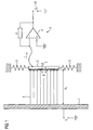
- FIG. 1 shows a line 1, which represents an object whose electrical potential or voltage U is to be determined.
- a measuring electrode 2 is arranged in the rest distance d 0 , which is designed to oscillate.
- the ability to vibrate is here, only shown schematically, made possible by two springs 5.
- This arrangement allows a mechanical vibration of the measuring electrode 2 in the vibration direction r and thus in a direction which is parallel to the surface normal of the measuring electrode 2.
- the measuring electrode 2 is formed of a metal, so that due to influence in the electric field E of the line 1 results in a change in the state of charge of the measuring electrode 2.
- This transshipment can be detected by measuring a recharge current I.
- the charge-reversal current I is detected by a measuring device 3, which represents a reference potential carrier.
- the measuring device 3 comprises an amplifier 4 having a first input, which is electrically connected to the measuring electrode 2, and a second input, which is grounded. An output of the amplifier 4 is electrically connected via an electrical resistor R to the first input.
- the measuring electrode 2 is set in mechanical vibration in the direction of vibration r at the frequency f. This results in the following physical relationships:
- the modulation of the measuring capacitance C between measuring electrode 2 and line 1 leads to the charge-reversal current I, which is used in the context of an evaluation in two respects. On the one hand, it is used as part of a calibration step to determine the unknown capacity C; on the other hand, its effective value is used to determine the unknown voltage U by means of the capacitance determined in the calibration step. This will be explained in more detail below.
- FIG. 2 shows a diagram with a curve S. This represents the relationship between the effective charge-reversal current ⁇ I> and the rest distance d 0 dar.
- the effective charge-reversal current ⁇ I> is accordingly greater at point P1 than at point P2.
- points P1 and P2 are then also the time-dependent current and distance curves in FIG. 2 shown.
- the curve associated with the time-dependent charge-reversal current I is more distorted at point P1 than at point P2.
- the waveform of the charge-reversal current I is increasingly distorted. This effect can be used to determine the rest distance d 0 .
- the time behavior of the charge transfer currents is again in 3A compiled.
- the charging time dependent on the time t at the point P1 is denoted by I 1
- the charge reversal current at the point P2 is denoted by I 2 .
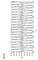
- I 1 and I 2 now a fast Fourier transform (FFT) is performed. This results in the 3B illustrated amplitude spectrum for the Umladestrom.
- the abscissa represents the frequency f in hertz, while the ordinate represents the amplitude of the charge-reversal current Î 'in amperes.
- the charge-reversal current I 1 has a plurality of frequency components.
- This ratio v can now be clearly assigned a rest distance d 0 via a calibration curve. This is for a calibration curve K1 in FIG. 4 shown. There is a linear relationship between the ratio v and the rest distance d 0 . This allows a conclusion from v to d 0 . This ratio is also independent of the unknown potential. The evaluation of this ratio is used for calibration as part of the measurement process.
- a distance weighted by the dielectric constant ⁇ for example a distance of the form d 0 / ⁇ , may also be applied.
- the capacitance C can now be deduced when the dielectric constant ⁇ and known area A are known. In principle, a determination of the voltage U from the measured charge-reversal current I is possible. The calibration step in the process is completed.
- the effective value ⁇ I> of the charge-reversal current I is then formed, for example. Since there is a linear relationship of the effective charge-reversal current ⁇ I> to the unknown potential U, it is possible to directly deduce the unknown potential U via a calibration curve K2. This connection is in FIG. 5 shown.
- the method thus allows a non-contact measurement of unknown potentials with a vibrating electrode, which moves transversely to the unknown potential.
- the oscillation frequency is significantly higher than the largest frequency to be measured of a time-dependent voltage U (t).
- the charge transfer currents I occurring at the oscillating measuring electrode 2 are spectrally evaluated in order to determine the basic distance d 0 between the measuring electrode 2 and the object to be measured (line 1). After this calibration, the charge-reversal current I is used for recalculation to the unknown potential U during measurement operation.
Landscapes
- Physics & Mathematics (AREA)
- General Physics & Mathematics (AREA)
- Measurement Of Resistance Or Impedance (AREA)
- Measurement Of Length, Angles, Or The Like Using Electric Or Magnetic Means (AREA)
- Investigating Or Analyzing Materials By The Use Of Electric Means (AREA)
Description
- Die Erfindung betrifft ein Verfahren und eine Vorrichtung zum berührungslosen Bestimmen eines elektrischen Potentials eines Objekts.
- Es ist bekannt, den Stromfluss durch ein Objekt berührungslos zu messen. Dies kann über induktive Kopplung, den Hall-Effekt oder den GMR(Giant Magneto Resistance)-Effekt erfolgen. Um berührungslos elektrische Leistung messen zu können, ist jedoch neben der berührungslosen Strommessung auch ein Verfahren zur berührungslosen Potentialmessung erforderlich. Die berührungslose Potentialmessung, insbesondere hoher Spannungen, ist v.a. im Bereich Smart Metering, Smart Grid und Response-Demand-Strategien von besonderer Bedeutung.
- Eine Möglichkeit hierfür bieten so genannte Elektrofeldmeter. Diese nutzen den Effekt der Influenz, um über die ermittelte elektrische Feldstärke auf die zu bestimmende Spannung schließen zu können. Dafür müssen jedoch der Abstand zwischen dem Objekt, dessen Potential bestimmt werden soll, und der Messelektrode des Elektrofeldmeters sowie das Material (Dielektrikum) zwischen Messelektrode und Objekt in der Messkapazität exakt bekannt sein. Um mit einem Elektrofeldmeter auch Gleichspannungen messen zu können, wird in der Regel zwischen der Messelektrode und dem Objekt ein Shutter (Feldblende) in Form eines Choppers (Flügelrad) eingesetzt.
- Für die Bestimmung reiner Wechselspannungen sind auch kapazitive Spannungsteiler nutzbar, wobei hier ebenfalls die Koppelkapazität zwischen einer Referenzelektrode und dem zu messenden Potential bekannt sein muss.
- Beide Verfahren bzw. Vorrichtungen (Elektrofeldmeter und kapazitiver Spannungsteiler) setzen eine genaue Kenntnis der Ankopplung an die zu messende Spannung voraus, insbesondere des Abstands zwischen Messelektrode und Messobjekt. Insofern sind diese bekannten Verfahren für nur temporäre Messvorgänge oder nachträgliche Messinstallationen ungeeignet. Elektrofeldmeter und kapazitive Spannungsteiler werden für präzise Messungen fest installiert und in der Einbauumgebung kalibriert. Bei Handmessgeräten ist eine exakte Kenntnis der Geometrie und stofflichen Beschaffenheit (Leitungsisolation, Luft, Gas, Betauung, etc.) des Messaufbaus nötig. Dazu werden bei handelsüblichen Elektrofeldmetern zum Beispiel spezielle Abstandshalter benutzt. Abstandshalter haben jedoch den Nachteil, dass sie insbesondere für die Potentialbestimmung elektrisch isolierter Leitungen nicht direkt auf dem leitenden Material aufsitzen und damit den Abstand nur unzureichend genau einstellen. Zudem kann die Art des isolierenden Materials nicht berücksichtigt werden. Reicht diese Präzision der bekannten berührungslosen Potentialmessverfahren nicht aus, muss üblicherweise kontaktierend gemessen werden.
- Die
US 4 205 267 A offenbart einen berührungslosen Spannungssensor. Der Sensor umfasst eine erste und eine zweite Elektrode, die bezüglich einer Oberfläche bewegt werden können. Zwischen den Elektroden und einem Objekt, dessen Potential bestimmt werden soll, ist eine Blende angeordnet. Damit können sowohl statische als auch dynamische Anteile des Potentials des Objekts ermittelt werden. - Des Weiteren beschreibt die
US 2007/065169 A1 eine Vorrichtung zum Messen eines elektrischen Potentials mit einer Elektrode. Die Vorrichtung umfasst einen Modulator zum Verändern der Kapazität zwischen der Elektrode und einem Objekt durch mechanische Vibrationen und einen Ladungsdetektor zum Erfassen der in die Elektrode induzierten elektrischen Ladung. - Die
GB 2 443 280 A - Schließlich beschreibt die
US 2007/247166 A1 eine Messeinrichtung zum Bestimmen eines Potentials. Die Messeinrichtung umfasst eine Detektionselektrode aus einem leitenden Material, die zu einem Objekt anordnenbar ist, eine bewegliche Struktur, die aus zumindest zwei Materialien mit unterschiedlichen Dielektrizitätskonstanten besteht, und einen Antriebsmechanismus zum Bewegen der beweglichen Struktur und zum Messen des elektrischen Potentials des Objektes. - Es ist Aufgabe der Erfindung, ein Verfahren sowie eine Vorrichtung bereitzustellen, mit denen eine berührungslose Potentialmessung auch bei zunächst unbekannter Koppelkapazität möglich ist.
- Diese Aufgabe wird durch ein Verfahren, welches die Merkmale des Patentanspruchs 1 aufweist, sowie eine Vorrichtung, welche die Merkmale des Patentanspruchs 7 aufweist, gelöst.
- Das erfindungsgemäße Verfahren dient zum berührungslosen Bestimmen eines elektrischen Potentials eines Objekts und umfasst die folgenden Schritte:
- a) Bereitstellen einer mechanisch schwingbeweglich ausgebildeten Elektrode, welche von dem Objekt räumlich beabstandet ist;
- b) Versetzen der Elektrode in mechanische Schwingung;
- c) Bestimmen einer zeitlichen Veränderung eines elektrischen Ladezustands der Elektrode;
- d) Ermitteln von Amplituden von zumindest zwei Frequenzkomponenten in der zeitlichen Veränderung des elektrischen Ladezustands;
- e) Bestimmen zumindest eines Parameters, welcher in den Wert einer elektrischen Kapazität der Anordnung aus Elektrode und Objekt eingeht, mittels der ermittelten Amplituden;
- f) Ermitteln der elektrischen Kapazität der Anordnung aus Elektrode und Objekt anhand des bestimmten Parameters; g) Ermitteln des elektrischen Potentials aus der bestimmten Veränderung des elektrischen Ladezustands und der ermittelten Kapazität;
- d1) Bestimmen einer ersten Amplitude bei einer ersten Frequenz;
- d2) Bestimmen einer zweiten Amplitude bei einer zweiten Frequenz, deren Wert ein ganzzahliges Vielfaches des Werts der ersten Frequenz ist; und
- e1) Bestimmen eines Ruheabstands der Elektrode zu dem Objekt aus dem Verhältnis der ersten zur zweiten Amplitude.
- Im Rahmen des Verfahrens kann also die Koppelkapazität zwischen der Elektrode und dem Objekt unmittelbar bestimmt werden, sodass insbesondere keine vorherige Kenntnis oder Festeinstellung dieser Kapazität für die Potentialmessung erforderlich ist. Der eigentlichen Potentialmessung geht damit im Rahmen des Verfahrens quasi ein Kalibrierschritt voraus, durch den unbekannte Parameter ermittelt werden können, welche erforderlich sind, um die Koppelkapazität zu bestimmen. Im Unterschied zum Einsatz von Elektrofeldmetern oder kapazitiven Spannungsteilern ist beim Einsatz der beschriebenen Methode kein Wissen über den Abstand der Elektrode von dem Objekt bzw. kein Wissen über die Dielektrizitätskonstante des Materials zwischen der Elektrode und dem Objekt bei berührungsloser Potentialmessung erforderlich. Eine exakte mechanische Justage bzw. ein definierter Festeinbau eines Messgeräts entfällt. Im Rahmen des Verfahrens kann die Kapazität exakt bestimmt werden. Damit sind sehr präzise berührungslose Messungen des unbekannten Potentials möglich.
- Bei der Frequenz kann es sich insbesondere um jene Frequenz handeln, welche die zeitliche Veränderung des elektrischen Ladezustands der Elektrode charakterisiert. Besonders bevorzugt ist es, die zweite Amplitude bei einer zweiten Frequenz zu bestimmen, deren Wert doppelt so groß ist wie der Wert der ersten Frequenz. Alternativ zur Bestimmung des Ruheabstands kann aus dem Verhältnis der ersten zur zweiten Amplitude auch ein mit einer Dielektrizitätskonstante gewichteter effektiver Ruheabstandswert bestimmt werden. Besonders bevorzugt ist es, die zeitliche Veränderung des elektrischen Ladezustands über ein vorgegebenes Zeitintervall hinweg zu bestimmen und an dem so bestimmten Verlauf eine Fourier-Analyse durchzuführen. Aus der Fourier-Analyse können sich dann vorzugsweise die von den Frequenzkomponenten abhängigen Amplituden ergeben, sodass eine erste Amplitude bei einer Grundfrequenz und die zweite Amplitude bei einer hierzu korrespondierenden Oberfrequenz ermittelbar und daraus das Verhältnis bestimmbar ist. Diese Art der Messung ist vergleichsweise einfach und erlaubt exakte Rückschlüsse auf den Ruheabstand der Elektrode zu dem Objekt. Eine direkte Abstandsmessung, beispielsweise über mechanische Abstandshalter, ist nicht erforderlich. Der Kalibriervorgang ist insgesamt einfach und aufwandsarm. Eine direkte Kontaktierung des Objekts, dessen Potential bestimmt werden soll, ist im Rahmen des Verfahrens nicht erforderlich. Damit kann auch das Potential von schwer zugänglichen Objekten bestimmt werden.
- Vorzugsweise erfolgt in Schritt e) das Bestimmen des zumindest einen Parameters über einen mathematischen Zusammenhang und/oder eine Kalibrierkurve. Dann ist lediglich eine Eichmessung erforderlich, über welche die Kalibrierkurve bzw. der mathematische Zusammenhang bestimmt wird, und es kann den Amplitudenwerten eindeutig der zumindest eine Parameter zugeordnet werden.
- Vorzugsweise wird in Schritt b) die Elektrode so in mechanische Schwingung versetzt, dass ihre Schwingungsrichtung parallel zu einer elektrischen Feldlinie verläuft, welche durch das elektrische Potential des Objekts verursacht wird. Dann ist sehr definierte physikalische Situation geschaffen und die Bestimmung der Koppelkapazität zwischen Objekt und Elektrode kann sehr einfach erfolgen. Es werden sehr präzise Messungen möglich.
- Vorzugsweise erfolgt in Schritt c) das Bestimmen der zeitlichen Veränderung des elektrischen Ladezustands der Elektrode durch Messung eines Umladestroms. Hierfür kann ein Bezugspotentialträger mit der Elektrode elektrisch verbunden sein und zwischen der Elektrode und dem Bezugspotentialträger ein Strommessgerät angeordnet sein. Besonders bevorzugt ist eine Anordnung unter Verwendung eines Verstärkers, mittels dessen die an der Elektrode abfallende Spannung mit einer vorgebbaren Referenzspannung verglichen wird. Strommessungen sind sehr präzise durchführbar und erlauben demgemäß sehr genaue Rückschlüsse auf das zu bestimmende elektrische Potential. Besonders bevorzugt kann für das Ermitteln des elektrischen Potentials ein effektiver Umladestrom bestimmt werden.
- Vorzugsweise wird in Schritt g) das elektrische Potential über einen mathematischen Zusammenhang und/oder eine Kalibrierkurve aus der bestimmten Veränderung des elektrischen Ladezustands ermittelt.
- Das Verfahren erlaubt die Bestimmung eines zeitlich konstanten Potentials an dem Objekt. Bereits durch die Schwingung der Elektrode wird eine zeitlich veränderliche Ladezustandsänderung an der Elektrode geschaffen, welche gemessen werden kann. Vorzugsweise kann mittels des Verfahrens jedoch auch ein elektrisches Potential des Objekts bestimmt werden, das zeitlich veränderlich ist und durch eine elektrische Schwingungsfrequenz charakterisierbar ist. Die Elektrode in Schritt b) wird dabei vorzugsweise so in mechanische Schwingung versetzt, dass die zugehörige mechanische Schwingungsfrequenz größer als die elektrische Schwingungsfrequenz ist. Besonders bevorzugt ist ein sehr hohes Verhältnis der mechanischen Schwingungsfrequenz zur elektrischen Schwingungsfrequenz. Dann sieht die Elektrode quasi ein zeitlich konstantes Potential an dem Objekt und es kann eine entkoppelte Betrachtung durchgeführt werden. Sowohl für AC- als auch DC-Messungen wird dann kein Shutter bzw. Flügelrad benötigt.
- Eine erfindungsgemäße Vorrichtung dient zur berührungslosen Bestimmung eines elektrischen Potentials eines Objekts und umfasst:
- eine mechanisch schwingbeweglich ausgebildete Elektrode, welche von dem Objekt räumlich beabstandet anordenbar ist;
- eine Messvorrichtung, welche dazu ausgebildet ist, eine zeitliche Veränderung eines elektrischen Ladezustands der Elektrode zu bestimmen; und
- eine Auswertevorrichtung, welche dazu ausgebildet ist, Amplituden von zumindest zwei Frequenzkomponenten in der zeitlichen Veränderung des elektrischen Ladezustands zu ermitteln, zumindest einen Parameter, welcher in den Wert einer elektrischen Kapazität der Anordnung aus Elektrode und Objekt eingeht, mittels der ermittelten Amplituden zu bestimmen, die elektrische Kapazität der Anordnung aus Elektrode und Objekt anhand des bestimmten Parameters zu ermitteln, und das elektrische Potential aus der bestimmten Veränderung des elektrischen Ladezustands und der ermittelten Kapazität zu ermitteln, wobei die Auswertevorrichtung dazu ausgebildet ist, eine erste Amplitude bei einer ersten Frequenz und eine zweite Amplitude bei einer zweiten Frequenz, deren Wert ein ganzzahliges Vielfaches des Werts der ersten Frequenz ist, zu bestimmen und einen Ruheabstand der Elektrode zu dem Objekt aus dem Verhältnis der ersten zur zweiten Amplitude zu bestimmen.
- Vorzugsweise ist die Elektrode als elektrisch leitfähige Platte ausgebildet, welche im Wesentlichen in Richtung der Plattennormalen schwingbeweglich ist, wobei die Platte vorzugsweise elektrisch mit der Messvorrichtung verbunden ist, welche als Strommessgerät ausgebildet ist.
- Die mit Bezug auf das erfindungsgemäße Verfahren dargestellten bevorzugten Ausführungsformen und deren Vorteile gelten entsprechend für die erfindungsgemäße Vorrichtung.
- Anhand von Ausführungsbeispielen wird die Erfindung im Folgenden näher erläutert. Es zeigen:
- FIG 1
- eine schematische Darstellung einer Vorrichtung zur Messung eines unbekannten Potentials einer Leitung;
- FIG 2
- die Abhängigkeit eines effektiven Umladestroms vom Ruheabstand der Messelektrode vom Leiter;
- FIG 3A
- die Abhängigkeit eines Umladestroms von der Zeit für zwei verschiedene Abstände der Messelektrode von der Leitung;
- FIG 3B
- ein über Fouriertransformation aus den Kurven der
FIG 3A erhaltenes Amplitudenspektrum; - FIG 4
- eine Kalibrationskurve, welche jedem Amplitudenverhältnis des Amplitudenspektrums der
FIG 3B einen Ruheabstand zuordnet; und - FIG 5
- eine Kalibrationskurve, welche jedem effektiven Stromwert einen Spannungswert der Leitung zuordnet.
- In den Figuren sind gleiche oder funktionsgleiche Elemente mit den gleichen Bezugszeichen versehen.
-
FIG 1 zeigt eine Leitung 1, welche ein Objekt darstellt, dessen elektrisches Potential bzw. Spannung U bestimmt werden soll. Hierfür ist im Ruheabstand d0 eine Messelektrode 2 angeordnet, welche schwingbeweglich ausgebildet ist. Die Fähigkeit zur Schwingung wird hier, nur schematisch dargestellt, über zwei Federn 5 ermöglicht. Diese Anordnung erlaubt eine mechanische Schwingung der Messelektrode 2 in Schwingungsrichtung r und damit in eine Richtung, welche parallel zur Flächennormalen der Messelektrode 2 verläuft. Die Messelektrode 2 ist aus einem Metall ausgebildet, sodass sich aufgrund von Influenz im elektrischen Feld E der Leitung 1 eine Änderung des Ladezustands der Messelektrode 2 ergibt. Diese Umladung kann über die Messung eines Umladestroms I erfasst werden. Der Umladestrom I wird hierbei von einer Messvorrichtung 3 erfasst, welche einen Bezugspotentialträger darstellt. - Die Messvorrichtung 3 umfasst einen Verstärker 4 mit einem ersten Eingang, welcher mit der Messelektrode 2 elektrisch verbunden ist, und einen zweiten Eingang, welcher geerdet ist. Ein Ausgang des Verstärkers 4 ist über einen elektrischen Widerstand R mit dem ersten Eingang elektrisch verbunden.
- Im Rahmen des Messverfahrens wird die Messelektrode 2 in mechanische Schwingung in Schwingungsrichtung r mit der Frequenz f versetzt. Es ergeben sich die folgenden physikalischen Zusammenhänge:
- Durch die Leitung 1 und die Messelektrode 2 ist eine Plattenkondensatoranordnung mit einer Koppelkapazität C geschaffen. Die Kapazität C berechnet sich gemäß

- ε ist hierbei die Dielektrizitätskonstante des die Kondensatoranordnung ausfüllenden Mediums;
- A ist die Fläche der Messelektrode 2; und
- d ist der zeitabhängige Abstand zwischen der Messelektrode 2 und der Leitung 1.
- Mit der Kreisfrequenz


- Der jeweils fließende Umladestrom I beträgt folglich:

- Die Modulation der Messkapazität C zwischen Messelektrode 2 und Leitung 1 führt zu dem Umladestrom I, der im Rahmen einer Auswertung in zweifacher Hinsicht herangezogen wird. Einerseits wird er im Rahmen eines Kalibrierschritts verwendet, um die unbekannte Kapazität C zu bestimmen; andererseits wird sein Effektivwert herangezogen, um mittels der im Kalibrierschritt ermittelten Kapazität die unbekannte Spannung U zu bestimmen. Dies sei im Folgenden näher erläutert.
-
FIG 2 zeigt ein Diagramm mit einer Kurve S. Diese stellt den Zusammenhang zwischen dem effektiven Umladestrom <I> und dem Ruheabstand d0 dar. Es sind exemplarisch zwei Punkte P1 und P2 auf der Kurve S eingezeichnet. Am Punkt P1 beträgt der Ruheabstand d0=0,3 mm, während er am Punkt P2 d0=0,9 mm beträgt. Der effektive Umladestrom <I> ist demgemäß am Punkt P1 größer als am Punkt P2. - Für die Punkte P1 und P2 sind dann jeweils auch die zeitabhängigen Strom- und Abstandsverläufe in
FIG 2 dargestellt. Wie man einem Vergleich der Stromverläufe in den Punkten P1 und P2 entnehmen kann, ist am Punkt P1 die zum zeitabhängigen Umladestrom I gehörige Kurve stärker verzerrt als am Punkt P2. Bei geringer werdendem Grundabstand bzw. Ruheabstand d0 wird also die Signalform des Umladestroms I zunehmend verzerrt. Dieser Effekt kann dazu genutzt werden, den Ruheabstand d0 zu bestimmen. - Das Zeitverhalten der Umladeströme ist nochmals in
FIG 3A zusammengestellt. Der von der Zeit t abhängige Umladestrom am Punkt P1 sei mit I1 bezeichnet, während der Umladestrom am Punkt P2 mit I2 bezeichnet ist. An den Umladestromverläufen I1 und I2 wird nun eine Fast-Fouriertransformation (FFT) durchgeführt. Hierdurch ergibt sich das inFIG 3B dargestellte Amplitudenspektrum für den Umladestrom. Auf der Abszisse ist die Frequenz f in Hertz angetragen, während auf der Ordinate die Amplitude des Umladestroms Î in Ampere dargestellt ist. Der Umladestrom I1 weist mehrere Frequenzkomponenten auf. Die Amplitude bei der Grundfrequenz f=1000 Hz sei mit Î1(f) bezeichnet; bei der ersten Oberfrequenz 2f=2000 Hz beträgt die Amplitude Î1(2f). Das Verhältnis dieser beiden Amplituden berechnet sich gemäß
und beträgt v1=2,91. - Ebenso kann für den Umladestrom I2 in
FIG 3A verfahren werden. Auch an seinem zeitabhängigen Verlauf kann eine Fourier-Analyse durchgeführt werden, sodass sich ein ebenfalls inFIG 3B dargestelltes Amplitudenspektrum mit den Amplituden Î2(f) und Î2(2f) ergibt. Auch hier berechnet sich das Amplitudenverhältnis gemäß
sodass sich der Wert v2=8,98 einstellt. Betrachtet man die inFIG 3B dargestellten Spektren für die beiden Ruheabstände 0,3 mm und 0,9 mm, so erkennt man, dass die Oberwellen mit zunehmendem Ruheabstand d0 geringer werden. Das Verhältnis von Grund- zu erster Oberwelle nimmt entsprechend zu. - Diesem Verhältnis v kann nunmehr über eine Kalibrierkurve eindeutig ein Ruheabstand d0 zugeordnet werden. Dies ist für eine Kalibrationskurve K1 in
FIG 4 dargestellt. Es besteht ein linearer Zusammenhang zwischen dem Verhältnis v und dem Ruheabstand d0. Damit ist ein Rückschluss von v auf d0 möglich. Dieses Verhältnis ist zudem vom unbekannten Potential unabhängig. Die Auswertung dieses Verhältnisses dient zur Kalibrierung im Rahmen des Messverfahrens. Gegebenenfalls kann statt des Ruheabstands d0 auf der Abszisse auch ein mit der Dielektrizitätskonstante ε gewichteter Abstand, z.B. ein Abstand der Form d0/ε, aufgetragen sein. Mit der Bestimmung des Ruheabstands d0 kann nunmehr bei bekannter Dielektrizitätskonstante ε und bekannter Fläche A auf die Kapazität C rückgeschlossen werden. Damit ist prinzipiell eine Bestimmung der Spannung U aus dem gemessenen Umladestrom I möglich. Der Kalibrierschritt im Rahmen des Verfahrens ist damit abgeschlossen. - Im eigentlichen Messbetrieb wird dann beispielsweise der Effektivwert <I> des Umladestroms I gebildet. Da ein linearer Zusammenhang des effektiven Umladestroms <I> zum unbekannten Potential U besteht, kann über eine Kalibrierkurve K2 direkt auf das unbekannte Potential U geschlossen werden. Dieser Zusammenhang ist in
FIG 5 dargestellt. - Im Ausführungsbeispiel der
FIG 2 bis 5 wurden folgende Annahmen getroffen: Frequenz f=1kHz; Schwingungsamplitude δ=100µm; und Fläche A=100mm2. - Die beiden Teilschritte des Messverfahrens seien nochmals zusammengefasst:
- 1. In einem Kalibrierschritt wird die Messelektrode 2 vor der Leitung 1 positioniert. Der Ruheabstand d0 ist nach der Installation nicht exakt bekannt; eine Kalibrierung ist nötig. Hierfür wird die Messelektrode 2 in Schwingung versetzt und der Umladestrom I in der schwingenden Messelektrode 2 spektral ausgewertet. Man betrachtet die Amplituden Î(f) bzw. Î(2f) an der Schwingfrequenz f und an der ersten Oberwelle 2f. Das Verhältnis v der Amplitude Î(f) der Grundfrequenz zur Amplitude Î(2f) der ersten Oberwelle ist dabei direkt proportional zum Ruheabstand d0 und unabhängig von der unbekannten Spannung U. Das Verfahren ermöglicht damit eine Bestimmung des Grundabstands bzw. Ruheabstands d0.
- 2. In einem Messschritt wird der Effektivwert <I> des Umladestroms I an der schwingenden Messelektrode 2 gebildet. Es besteht ein proportionaler Zusammenhang zwischen dem Umladestrom <I> an der Messelektrode 2 und dem unbekannten Potential U. Der zugehörige Proportionalitätsfaktor (typischerweise die Kapazität C) wird vorab im Kalibrierschritt 1 bestimmt.
- Das Verfahren erlaubt folglich eine berührungslose Messung unbekannter Potentiale mit einer schwingenden Elektrode, welche sich transversal zum unbekannten Potential bewegt. Die Schwingfrequenz liegt dabei deutlich höher als die größte zu messende Frequenz einer zeitlich abhängigen Spannung U(t). Weiterhin werden die an der schwingenden Messelektrode 2 auftretenden Umladeströme I spektral ausgewertet, um den Grundabstand d0 zwischen Messelektrode 2 und Messobjekt (Leitung 1) zu bestimmen. Nach dieser Kalibrierung wird im Messbetrieb der Umladestrom I zur Rückrechnung auf das unbekannte Potential U benutzt.
-
- 1
- Leitung
- 2
- Messelektrode
- 3
- Messvorrichtung
- 4
- Verstärker
- 5
- Feder
- d
- Abstand
- d0
- Ruheabstand
- δ
- Schwingungsamplitude
- U
- Spannung
- I, I1, I2
- Umladestrom
- I, Î1, Î2
- Amplitude des Umladestroms
- <I>
- effektiver Umladestrom
- f
- Frequenz
- C
- Kapazität
- v, v1, v2
- Verhältnis
- ε
- Dielektrizitätskonstante
- K1
- Kurve
- K2
- Kurve
- S
- Kurve
- P1
- Punkt
- P2
- Punkt
- r
- Schwingungsrichtung
- E
- elektrisches Feld
- U0
- Spannung
- R
- Widerstand
- t
- Zeit
- A
- Fläche
- ω
- Kreisfrequenz
Claims (8)
- Verfahren zum berührungslosen Bestimmen eines elektrischen Potentials (U) eines Objekts (1) mit den Schritten:a) Bereitstellen einer mechanisch schwingbeweglich ausgebildeten Elektrode (2), welche von dem Objekt (1) räumlich beabstandet (d0) ist;b) Versetzen der Elektrode (2) in mechanische Schwingung (f);c) Bestimmen einer zeitlichen Veränderung eines elektrischen Ladezustands der Elektrode (I);d) Ermitteln von Amplituden (Î(f), Î(2f)) von zumindest zwei Frequenzkomponenten (f, 2f) in der zeitlichen Veränderung des elektrischen Ladezustands (I);e) Bestimmen zumindest eines Parameters (ε, d0), welcher in den Wert einer elektrischen Kapazität (C) der Anordnung aus Elektrode (2) und Objekt (1) eingeht, mittels der ermittelten Amplituden (Î(f), Î(2f));f) Ermitteln der elektrischen Kapazität (C) der Anordnung aus Elektrode (2) und Objekt (1) anhand des bestimmten Parameters (ε, d0); undg) Ermitteln des elektrischen Potentials (U) aus der bestimmten Veränderung des elektrischen Ladezustands (I) und der ermittelten Kapazität (C);gekennzeichnet durch die Schritte:d1) Bestimmen einer ersten Amplitude (Î(f)) bei einer ersten Frequenz (f);d2) Bestimmen einer zweiten Amplitude (Î(2f)) bei einer zweiten Frequenz (2f), deren Wert ein ganzzahliges Vielfaches des Werts der ersten Frequenz (f) ist; unde1) Bestimmen eines Ruheabstands (d0) der Elektrode (2) zu dem Objekt (1) aus dem Verhältnis (v) der ersten (Î(f)) zur zweiten Amplitude (Î(2f)).
- Verfahren nach Anspruch 1, dadurch gekennzeichnet, dass in Schritt e) das Bestimmen des zumindest einen Parameters (ε, d0) über einen mathematischen Zusammenhang und/oder eine Kalibrierkurve (K1) erfolgt.
- Verfahren nach einem der vorhergehenden Ansprüche, dadurch gekennzeichnet, dass in Schritt b) die Elektrode (2) so in mechanische Schwingung versetzt wird, dass ihre Schwingungsrichtung (r) parallel zu einer elektrischen Feldlinie (E) verläuft, welche durch das elektrische Potential (U) des Objekts (1) verursacht wird.
- Verfahren nach einem der vorhergehenden Ansprüche, dadurch gekennzeichnet, dass in Schritt c) das Bestimmen der zeitlichen Veränderung des elektrischen Ladezustands der Elektrode (2) durch Messung eines Umladestroms (I) erfolgt.
- Verfahren nach einem der vorhergehenden Ansprüche, dadurch gekennzeichnet, dass in Schritt g) das elektrische Potential (U) über einen mathematischen Zusammenhang und/oder eine Kalibrierkurve (K2) aus der bestimmten Veränderung des elektrischen Ladezustands (I) ermittelt wird.
- Verfahren nach einem der vorhergehenden Ansprüche, dadurch gekennzeichnet, dass das elektrische Potential (U) zeitlich veränderlich ist und durch eine elektrische Schwingungsfrequenz charakterisierbar ist, und die Elektrode (2) in Schritt b) so in mechanische Schwingung versetzt wird, dass die zugehörige mechanische Schwingungsfrequenz (f) größer als die elektrische Schwingungsfrequenz ist.
- Vorrichtung zur berührungslosen Bestimmung eines elektrischen Potentials (U) eines Objekts (1) mit:- einer mechanisch schwingbeweglich ausgebildeten Elektrode (2), welche von dem Objekt (1) räumlich beabstandet (d0) anordenbar ist;- einer Messvorrichtung (3), welche dazu ausgebildet ist, eine zeitliche Veränderung eines elektrischen Ladezustands (I) der Elektrode (2) zu bestimmen; und- einer Auswertevorrichtung, welche dazu ausgebildet ist, Amplituden (Î(f), Î(2f)) von zumindest zwei Frequenzkomponenten (f, 2f) in der zeitlichen Veränderung des elektrischen Ladezustands (I) zu ermitteln, zumindest einen Parameter (ε, d0), welcher in den Wert einer elektrischen Kapazität (C) der Anordnung aus Elektrode (2) und Objekt (1) eingeht, mittels der ermittelten Amplituden (Î(f), Î(2f)) zu bestimmen, die elektrische Kapazität (C) der Anordnung aus Elektrode (2) und Objekt (1) anhand des bestimmten Parameters (ε, d0) zu ermitteln, und das elektrische Potential (U) aus der bestimmten Veränderung des elektrischen Ladezustands (I) und der ermittelten Kapazität (C) zu ermitteln,dadurch gekennzeichnet, dass- die Auswertevorrichtung dazu ausgebildet ist, eine erste Amplitude (Î(f)) bei einer ersten Frequenz (f) und eine zweite Amplitude (Î(2f)) bei einer zweiten Frequenz (2f), deren Wert ein ganzzahliges Vielfaches des Werts der ersten Frequenz (f) ist, zu bestimmen und einen Ruheabstand (d0) der Elektrode (2) zu dem Objekt (1) aus dem Verhältnis (v) der ersten (Î(f)) zur zweiten Amplitude (Î(2f)) zu bestimmen.
- Vorrichtung nach Anspruch 7, dadurch gekennzeichnet, dass die Elektrode (2) als elektrisch leitfähige Platte ausgebildet ist, welche im Wesentlichen in Richtung (r) der Plattennormalen schwingbeweglich ist, und die Platte elektrisch mit der Messvorrichtung (3) verbunden ist, welche als Strommessgerät ausgebildet ist.
Applications Claiming Priority (1)
| Application Number | Priority Date | Filing Date | Title |
|---|---|---|---|
| PCT/EP2011/055957 WO2012139651A1 (de) | 2011-04-14 | 2011-04-14 | Verfahren zum berührungslosen bestimmen eines elektrischen potentials mit einer schwingbeweglich ausgebildeten elektrode sowie vorrichtung |
Publications (2)
| Publication Number | Publication Date |
|---|---|
| EP2656086A1 EP2656086A1 (de) | 2013-10-30 |
| EP2656086B1 true EP2656086B1 (de) | 2015-03-18 |
Family
ID=44625894
Family Applications (1)
| Application Number | Title | Priority Date | Filing Date |
|---|---|---|---|
| EP20110714977 Not-in-force EP2656086B1 (de) | 2011-04-14 | 2011-04-14 | Verfahren zum berührungslosen bestimmen eines elektrischen potentials mit einer schwingbeweglich ausgebildeten elektrode sowie vorrichtung |
Country Status (5)
| Country | Link |
|---|---|
| US (1) | US9121878B2 (de) |
| EP (1) | EP2656086B1 (de) |
| JP (1) | JP2014510928A (de) |
| CN (1) | CN103460057B (de) |
| WO (1) | WO2012139651A1 (de) |
Families Citing this family (4)
| Publication number | Priority date | Publication date | Assignee | Title |
|---|---|---|---|---|
| JP5727074B1 (ja) * | 2014-06-04 | 2015-06-03 | 長谷川電機工業株式会社 | 直流電圧検出器 |
| JP6305236B2 (ja) * | 2014-06-18 | 2018-04-04 | 日置電機株式会社 | 非接触型電圧検出装置 |
| TWI649568B (zh) * | 2014-10-17 | 2019-02-01 | 日商日置電機股份有限公司 | Voltage detecting device |
| DE102015208173A1 (de) * | 2015-05-04 | 2016-11-10 | Siemens Aktiengesellschaft | Verfahren und Messanordnung zur Spannungsmessung, Anordnung mit einem Sensor sowie Verwendung eines Sensors zur Spannungsmessung |
Family Cites Families (8)
| Publication number | Priority date | Publication date | Assignee | Title |
|---|---|---|---|---|
| US4205267A (en) * | 1977-11-03 | 1980-05-27 | Williams Bruce T | High speed electrostatic voltmeter |
| US5473244A (en) | 1992-09-17 | 1995-12-05 | Libove; Joel M. | Apparatus for measuring voltages and currents using non-contacting sensors |
| JP3481720B2 (ja) * | 1995-03-31 | 2003-12-22 | 株式会社リコー | 表面電位測定装置 |
| US6573725B2 (en) * | 2001-08-24 | 2003-06-03 | Trek, Inc. | Sensor for non-contacting electrostatic detector |
| JP2004301554A (ja) | 2003-03-28 | 2004-10-28 | Canon Inc | 電位測定装置及び画像形成装置 |
| US7372278B2 (en) * | 2005-08-16 | 2008-05-13 | Canon Kabushiki Kaisha | Electric potential measuring apparatus electrostatic capacitance measuring apparatus, electric potential measuring method, electrostatic capacitance measuring method, and image forming apparatus |
| GB0612071D0 (en) * | 2006-06-17 | 2006-07-26 | Kp Technology | Measurement device and method |
| JP4993349B2 (ja) * | 2007-01-29 | 2012-08-08 | キヤノン株式会社 | 電位測定装置、及び画像形成装置 |
-
2011
- 2011-04-14 US US14/111,712 patent/US9121878B2/en not_active Expired - Fee Related
- 2011-04-14 JP JP2014504179A patent/JP2014510928A/ja active Pending
- 2011-04-14 EP EP20110714977 patent/EP2656086B1/de not_active Not-in-force
- 2011-04-14 CN CN201180070096.3A patent/CN103460057B/zh not_active Expired - Fee Related
- 2011-04-14 WO PCT/EP2011/055957 patent/WO2012139651A1/de not_active Ceased
Also Published As
| Publication number | Publication date |
|---|---|
| US20140035598A1 (en) | 2014-02-06 |
| CN103460057B (zh) | 2016-06-22 |
| WO2012139651A1 (de) | 2012-10-18 |
| EP2656086A1 (de) | 2013-10-30 |
| CN103460057A (zh) | 2013-12-18 |
| US9121878B2 (en) | 2015-09-01 |
| JP2014510928A (ja) | 2014-05-01 |
Similar Documents
| Publication | Publication Date | Title |
|---|---|---|
| EP2668512B1 (de) | Verfahren zum berührungslosen bestimmen eines elektrischen potentials eines objekts durch zwei verschiedene werte für den elektrischen fluss sowie vorrichtung | |
| DE69804857T2 (de) | Integritätsprüfung von elektroden | |
| DE10243748A1 (de) | Elektromagnetischer Durchflussmesser | |
| DE102014119453A1 (de) | Verfahren zur Defekterkennung der Signalleitung zwischen einer Elektrode und einer Mess- und/oder Auswerteeinheit eines magnetisch-induktiven Durchflussmessgerätes | |
| DE102012006332A1 (de) | Verfahren zum Verorten eines Kabelfehlers in einem Prüfkabel und zugehörige Vorrichtung | |
| EP3293499B1 (de) | Verfahren zum betreiben eines magnetisch-induktiven durchflussmessgeräts und magnetisch-induktives durchflussmessgerät | |
| EP2215490B1 (de) | Verfahren zur detektion von interlaminaren blechschlüssen im stator-blechpaket von elektromaschinen | |
| EP2697659B1 (de) | Vorrichtung zur berührungslosen bestimmung eines elektrischen potentials eines objekts, stromzange sowie verfahren | |
| DE102018102535B3 (de) | Temperaturmessung mittels der Impedanz eines Ultraschalltransducers | |
| WO2012139651A1 (de) | Verfahren zum berührungslosen bestimmen eines elektrischen potentials mit einer schwingbeweglich ausgebildeten elektrode sowie vorrichtung | |
| DE10240243A1 (de) | Verfahren und Messanordnung zum Abgleich der Nullpunktdrift von Stromsensoren | |
| DE102017130720A1 (de) | Verfahren zur Defekterkennung der Signalleitung zwischen einer Messelektrode und einer Mess- und/oder Auswerteeinheit eines magnetisch-induktiven Durchflussmessgerätes | |
| WO2012031924A1 (de) | Verfahren zur überwachung der alterung eines organischen stoffes und messanordnung mit einem kondensator | |
| EP4071447B1 (de) | Verfahren zum bestimmen der leitfähigkeit eines mediums, betriebsverfahren eines magnetisch-induktiven durchflussmessgeräts, und magnetisch-induktives durchflussmessgerät | |
| DE102013004990B4 (de) | Verfahren zur Bestimmung der elektrischen Leitfähigkeit an Proben mittels eines Wirbelstromsensors | |
| DE2729821A1 (de) | Vorrichtung zum bestimmen des flusses eines gases | |
| EP2657726A2 (de) | Elektromagnetisches Leitfähigkeitsmesssystem mit verbesserter Driftkorrektur | |
| DE2021811C3 (de) | Einrichtung zur Messung der Dielektrizitätskonstanten von Stoffen | |
| EP1867422A2 (de) | Vorrichtung und Verfahren zur elektrochemischen Bearbeitung von Werkstücken | |
| DE102020131684A1 (de) | Gussformanordnung | |
| DE445576C (de) | Verfahren zur Messung des Modulationsgrads von Wechselstroemen | |
| DE1541745C (de) | Verfahren und Anordnung zum elektronischen Messen des ,zeitlichen Differentialquotienten von Wechselspannungen mit starker Störungsüberlagerung· | |
| DE102011008295A1 (de) | Verfahren zur Durchflussmessung | |
| DE1473863A1 (de) | Vorrichtung zum Ausmessen metallisch umkleideter Hohlraeume | |
| DD200826A1 (de) | Verfahren zur geoelektrischen erkundung unter nutzung von stoerfeldern |
Legal Events
| Date | Code | Title | Description |
|---|---|---|---|
| PUAI | Public reference made under article 153(3) epc to a published international application that has entered the european phase |
Free format text: ORIGINAL CODE: 0009012 |
|
| 17P | Request for examination filed |
Effective date: 20130726 |
|
| AK | Designated contracting states |
Kind code of ref document: A1 Designated state(s): AL AT BE BG CH CY CZ DE DK EE ES FI FR GB GR HR HU IE IS IT LI LT LU LV MC MK MT NL NO PL PT RO RS SE SI SK SM TR |
|
| DAX | Request for extension of the european patent (deleted) | ||
| GRAP | Despatch of communication of intention to grant a patent |
Free format text: ORIGINAL CODE: EPIDOSNIGR1 |
|
| RIC1 | Information provided on ipc code assigned before grant |
Ipc: G01R 27/26 20060101ALI20140930BHEP Ipc: G01R 19/00 20060101ALI20140930BHEP Ipc: G01R 19/155 20060101ALI20140930BHEP Ipc: G01R 15/14 20060101ALI20140930BHEP Ipc: G01R 29/12 20060101ALI20140930BHEP Ipc: G01R 19/165 20060101ALI20140930BHEP Ipc: G01R 31/312 20060101ALI20140930BHEP Ipc: G01R 15/16 20060101AFI20140930BHEP |
|
| INTG | Intention to grant announced |
Effective date: 20141015 |
|
| GRAS | Grant fee paid |
Free format text: ORIGINAL CODE: EPIDOSNIGR3 |
|
| GRAA | (expected) grant |
Free format text: ORIGINAL CODE: 0009210 |
|
| AK | Designated contracting states |
Kind code of ref document: B1 Designated state(s): AL AT BE BG CH CY CZ DE DK EE ES FI FR GB GR HR HU IE IS IT LI LT LU LV MC MK MT NL NO PL PT RO RS SE SI SK SM TR |
|
| REG | Reference to a national code |
Ref country code: GB Ref legal event code: FG4D Free format text: NOT ENGLISH |
|
| REG | Reference to a national code |
Ref country code: CH Ref legal event code: EP |
|
| REG | Reference to a national code |
Ref country code: IE Ref legal event code: FG4D Free format text: LANGUAGE OF EP DOCUMENT: GERMAN |
|
| REG | Reference to a national code |
Ref country code: AT Ref legal event code: REF Ref document number: 716898 Country of ref document: AT Kind code of ref document: T Effective date: 20150415 |
|
| REG | Reference to a national code |
Ref country code: DE Ref legal event code: R096 Ref document number: 502011006296 Country of ref document: DE Effective date: 20150430 |
|
| REG | Reference to a national code |
Ref country code: NL Ref legal event code: VDEP Effective date: 20150318 |
|
| REG | Reference to a national code |
Ref country code: NL Ref legal event code: VDEP Effective date: 20150318 |
|
| PG25 | Lapsed in a contracting state [announced via postgrant information from national office to epo] |
Ref country code: SE Free format text: LAPSE BECAUSE OF FAILURE TO SUBMIT A TRANSLATION OF THE DESCRIPTION OR TO PAY THE FEE WITHIN THE PRESCRIBED TIME-LIMIT Effective date: 20150318 Ref country code: LT Free format text: LAPSE BECAUSE OF FAILURE TO SUBMIT A TRANSLATION OF THE DESCRIPTION OR TO PAY THE FEE WITHIN THE PRESCRIBED TIME-LIMIT Effective date: 20150318 Ref country code: FI Free format text: LAPSE BECAUSE OF FAILURE TO SUBMIT A TRANSLATION OF THE DESCRIPTION OR TO PAY THE FEE WITHIN THE PRESCRIBED TIME-LIMIT Effective date: 20150318 Ref country code: HR Free format text: LAPSE BECAUSE OF FAILURE TO SUBMIT A TRANSLATION OF THE DESCRIPTION OR TO PAY THE FEE WITHIN THE PRESCRIBED TIME-LIMIT Effective date: 20150318 Ref country code: NO Free format text: LAPSE BECAUSE OF FAILURE TO SUBMIT A TRANSLATION OF THE DESCRIPTION OR TO PAY THE FEE WITHIN THE PRESCRIBED TIME-LIMIT Effective date: 20150618 |
|
| REG | Reference to a national code |
Ref country code: LT Ref legal event code: MG4D |
|
| PG25 | Lapsed in a contracting state [announced via postgrant information from national office to epo] |
Ref country code: GR Free format text: LAPSE BECAUSE OF FAILURE TO SUBMIT A TRANSLATION OF THE DESCRIPTION OR TO PAY THE FEE WITHIN THE PRESCRIBED TIME-LIMIT Effective date: 20150619 Ref country code: LV Free format text: LAPSE BECAUSE OF FAILURE TO SUBMIT A TRANSLATION OF THE DESCRIPTION OR TO PAY THE FEE WITHIN THE PRESCRIBED TIME-LIMIT Effective date: 20150318 Ref country code: RS Free format text: LAPSE BECAUSE OF FAILURE TO SUBMIT A TRANSLATION OF THE DESCRIPTION OR TO PAY THE FEE WITHIN THE PRESCRIBED TIME-LIMIT Effective date: 20150318 |
|
| PG25 | Lapsed in a contracting state [announced via postgrant information from national office to epo] |
Ref country code: NL Free format text: LAPSE BECAUSE OF FAILURE TO SUBMIT A TRANSLATION OF THE DESCRIPTION OR TO PAY THE FEE WITHIN THE PRESCRIBED TIME-LIMIT Effective date: 20150318 |
|
| PG25 | Lapsed in a contracting state [announced via postgrant information from national office to epo] |
Ref country code: SK Free format text: LAPSE BECAUSE OF FAILURE TO SUBMIT A TRANSLATION OF THE DESCRIPTION OR TO PAY THE FEE WITHIN THE PRESCRIBED TIME-LIMIT Effective date: 20150318 Ref country code: RO Free format text: LAPSE BECAUSE OF FAILURE TO SUBMIT A TRANSLATION OF THE DESCRIPTION OR TO PAY THE FEE WITHIN THE PRESCRIBED TIME-LIMIT Effective date: 20150318 Ref country code: CZ Free format text: LAPSE BECAUSE OF FAILURE TO SUBMIT A TRANSLATION OF THE DESCRIPTION OR TO PAY THE FEE WITHIN THE PRESCRIBED TIME-LIMIT Effective date: 20150318 Ref country code: ES Free format text: LAPSE BECAUSE OF FAILURE TO SUBMIT A TRANSLATION OF THE DESCRIPTION OR TO PAY THE FEE WITHIN THE PRESCRIBED TIME-LIMIT Effective date: 20150318 Ref country code: EE Free format text: LAPSE BECAUSE OF FAILURE TO SUBMIT A TRANSLATION OF THE DESCRIPTION OR TO PAY THE FEE WITHIN THE PRESCRIBED TIME-LIMIT Effective date: 20150318 Ref country code: PT Free format text: LAPSE BECAUSE OF FAILURE TO SUBMIT A TRANSLATION OF THE DESCRIPTION OR TO PAY THE FEE WITHIN THE PRESCRIBED TIME-LIMIT Effective date: 20150720 |
|
| PG25 | Lapsed in a contracting state [announced via postgrant information from national office to epo] |
Ref country code: IS Free format text: LAPSE BECAUSE OF FAILURE TO SUBMIT A TRANSLATION OF THE DESCRIPTION OR TO PAY THE FEE WITHIN THE PRESCRIBED TIME-LIMIT Effective date: 20150718 Ref country code: MC Free format text: LAPSE BECAUSE OF FAILURE TO SUBMIT A TRANSLATION OF THE DESCRIPTION OR TO PAY THE FEE WITHIN THE PRESCRIBED TIME-LIMIT Effective date: 20150318 Ref country code: PL Free format text: LAPSE BECAUSE OF FAILURE TO SUBMIT A TRANSLATION OF THE DESCRIPTION OR TO PAY THE FEE WITHIN THE PRESCRIBED TIME-LIMIT Effective date: 20150318 |
|
| REG | Reference to a national code |
Ref country code: CH Ref legal event code: PL |
|
| REG | Reference to a national code |
Ref country code: DE Ref legal event code: R097 Ref document number: 502011006296 Country of ref document: DE |
|
| PLBE | No opposition filed within time limit |
Free format text: ORIGINAL CODE: 0009261 |
|
| STAA | Information on the status of an ep patent application or granted ep patent |
Free format text: STATUS: NO OPPOSITION FILED WITHIN TIME LIMIT |
|
| REG | Reference to a national code |
Ref country code: IE Ref legal event code: MM4A |
|
| PG25 | Lapsed in a contracting state [announced via postgrant information from national office to epo] |
Ref country code: CH Free format text: LAPSE BECAUSE OF NON-PAYMENT OF DUE FEES Effective date: 20150430 Ref country code: LI Free format text: LAPSE BECAUSE OF NON-PAYMENT OF DUE FEES Effective date: 20150430 Ref country code: DK Free format text: LAPSE BECAUSE OF FAILURE TO SUBMIT A TRANSLATION OF THE DESCRIPTION OR TO PAY THE FEE WITHIN THE PRESCRIBED TIME-LIMIT Effective date: 20150318 |
|
| 26N | No opposition filed |
Effective date: 20151221 |
|
| PG25 | Lapsed in a contracting state [announced via postgrant information from national office to epo] |
Ref country code: SI Free format text: LAPSE BECAUSE OF FAILURE TO SUBMIT A TRANSLATION OF THE DESCRIPTION OR TO PAY THE FEE WITHIN THE PRESCRIBED TIME-LIMIT Effective date: 20150318 |
|
| PG25 | Lapsed in a contracting state [announced via postgrant information from national office to epo] |
Ref country code: IE Free format text: LAPSE BECAUSE OF NON-PAYMENT OF DUE FEES Effective date: 20150414 |
|
| REG | Reference to a national code |
Ref country code: FR Ref legal event code: PLFP Year of fee payment: 6 |
|
| PG25 | Lapsed in a contracting state [announced via postgrant information from national office to epo] |
Ref country code: MT Free format text: LAPSE BECAUSE OF FAILURE TO SUBMIT A TRANSLATION OF THE DESCRIPTION OR TO PAY THE FEE WITHIN THE PRESCRIBED TIME-LIMIT Effective date: 20150318 |
|
| REG | Reference to a national code |
Ref country code: FR Ref legal event code: PLFP Year of fee payment: 7 |
|
| PG25 | Lapsed in a contracting state [announced via postgrant information from national office to epo] |
Ref country code: SM Free format text: LAPSE BECAUSE OF FAILURE TO SUBMIT A TRANSLATION OF THE DESCRIPTION OR TO PAY THE FEE WITHIN THE PRESCRIBED TIME-LIMIT Effective date: 20150318 Ref country code: HU Free format text: LAPSE BECAUSE OF FAILURE TO SUBMIT A TRANSLATION OF THE DESCRIPTION OR TO PAY THE FEE WITHIN THE PRESCRIBED TIME-LIMIT; INVALID AB INITIO Effective date: 20110414 Ref country code: BG Free format text: LAPSE BECAUSE OF FAILURE TO SUBMIT A TRANSLATION OF THE DESCRIPTION OR TO PAY THE FEE WITHIN THE PRESCRIBED TIME-LIMIT Effective date: 20150318 |
|
| REG | Reference to a national code |
Ref country code: AT Ref legal event code: MM01 Ref document number: 716898 Country of ref document: AT Kind code of ref document: T Effective date: 20160414 |
|
| PG25 | Lapsed in a contracting state [announced via postgrant information from national office to epo] |
Ref country code: CY Free format text: LAPSE BECAUSE OF FAILURE TO SUBMIT A TRANSLATION OF THE DESCRIPTION OR TO PAY THE FEE WITHIN THE PRESCRIBED TIME-LIMIT Effective date: 20150318 |
|
| PG25 | Lapsed in a contracting state [announced via postgrant information from national office to epo] |
Ref country code: BE Free format text: LAPSE BECAUSE OF NON-PAYMENT OF DUE FEES Effective date: 20150430 |
|
| PG25 | Lapsed in a contracting state [announced via postgrant information from national office to epo] |
Ref country code: AT Free format text: LAPSE BECAUSE OF NON-PAYMENT OF DUE FEES Effective date: 20160414 Ref country code: TR Free format text: LAPSE BECAUSE OF FAILURE TO SUBMIT A TRANSLATION OF THE DESCRIPTION OR TO PAY THE FEE WITHIN THE PRESCRIBED TIME-LIMIT Effective date: 20150318 |
|
| PG25 | Lapsed in a contracting state [announced via postgrant information from national office to epo] |
Ref country code: LU Free format text: LAPSE BECAUSE OF NON-PAYMENT OF DUE FEES Effective date: 20150414 |
|
| REG | Reference to a national code |
Ref country code: FR Ref legal event code: PLFP Year of fee payment: 8 |
|
| PG25 | Lapsed in a contracting state [announced via postgrant information from national office to epo] |
Ref country code: MK Free format text: LAPSE BECAUSE OF FAILURE TO SUBMIT A TRANSLATION OF THE DESCRIPTION OR TO PAY THE FEE WITHIN THE PRESCRIBED TIME-LIMIT Effective date: 20150318 |
|
| PGFP | Annual fee paid to national office [announced via postgrant information from national office to epo] |
Ref country code: DE Payment date: 20180619 Year of fee payment: 8 |
|
| PG25 | Lapsed in a contracting state [announced via postgrant information from national office to epo] |
Ref country code: AL Free format text: LAPSE BECAUSE OF FAILURE TO SUBMIT A TRANSLATION OF THE DESCRIPTION OR TO PAY THE FEE WITHIN THE PRESCRIBED TIME-LIMIT Effective date: 20150318 |
|
| PGFP | Annual fee paid to national office [announced via postgrant information from national office to epo] |
Ref country code: IT Payment date: 20190423 Year of fee payment: 9 |
|
| PGFP | Annual fee paid to national office [announced via postgrant information from national office to epo] |
Ref country code: FR Payment date: 20190425 Year of fee payment: 9 |
|
| PGFP | Annual fee paid to national office [announced via postgrant information from national office to epo] |
Ref country code: GB Payment date: 20190402 Year of fee payment: 9 |
|
| REG | Reference to a national code |
Ref country code: DE Ref legal event code: R119 Ref document number: 502011006296 Country of ref document: DE |
|
| PG25 | Lapsed in a contracting state [announced via postgrant information from national office to epo] |
Ref country code: DE Free format text: LAPSE BECAUSE OF NON-PAYMENT OF DUE FEES Effective date: 20191101 |
|
| PG25 | Lapsed in a contracting state [announced via postgrant information from national office to epo] |
Ref country code: FR Free format text: LAPSE BECAUSE OF NON-PAYMENT OF DUE FEES Effective date: 20200430 |
|
| GBPC | Gb: european patent ceased through non-payment of renewal fee |
Effective date: 20200414 |
|
| PG25 | Lapsed in a contracting state [announced via postgrant information from national office to epo] |
Ref country code: GB Free format text: LAPSE BECAUSE OF NON-PAYMENT OF DUE FEES Effective date: 20200414 |
|
| PG25 | Lapsed in a contracting state [announced via postgrant information from national office to epo] |
Ref country code: IT Free format text: LAPSE BECAUSE OF NON-PAYMENT OF DUE FEES Effective date: 20200414 |