EP2656484B1 - Machine a flux transversal - Google Patents
Machine a flux transversal Download PDFInfo
- Publication number
- EP2656484B1 EP2656484B1 EP11802712.7A EP11802712A EP2656484B1 EP 2656484 B1 EP2656484 B1 EP 2656484B1 EP 11802712 A EP11802712 A EP 11802712A EP 2656484 B1 EP2656484 B1 EP 2656484B1
- Authority
- EP
- European Patent Office
- Prior art keywords
- toothed
- toothed disks
- stator
- flux
- machine according
- Prior art date
- Legal status (The legal status is an assumption and is not a legal conclusion. Google has not performed a legal analysis and makes no representation as to the accuracy of the status listed.)
- Not-in-force
Links
- 230000004907 flux Effects 0.000 title claims description 36
- 230000014759 maintenance of location Effects 0.000 claims 1
- 239000004020 conductor Substances 0.000 description 11
- 238000004519 manufacturing process Methods 0.000 description 7
- 238000004382 potting Methods 0.000 description 6
- 238000004804 winding Methods 0.000 description 6
- 238000006798 ring closing metathesis reaction Methods 0.000 description 5
- 150000001875 compounds Chemical class 0.000 description 4
- 238000010276 construction Methods 0.000 description 3
- 239000003822 epoxy resin Substances 0.000 description 3
- 239000000463 material Substances 0.000 description 3
- 229920000647 polyepoxide Polymers 0.000 description 3
- 239000004814 polyurethane Substances 0.000 description 3
- 229920002635 polyurethane Polymers 0.000 description 3
- XEEYBQQBJWHFJM-UHFFFAOYSA-N Iron Chemical compound [Fe] XEEYBQQBJWHFJM-UHFFFAOYSA-N 0.000 description 2
- 210000000078 claw Anatomy 0.000 description 2
- 230000008878 coupling Effects 0.000 description 2
- 238000010168 coupling process Methods 0.000 description 2
- 238000005859 coupling reaction Methods 0.000 description 2
- 125000006850 spacer group Chemical group 0.000 description 2
- UAOUIVVJBYDFKD-XKCDOFEDSA-N (1R,9R,10S,11R,12R,15S,18S,21R)-10,11,21-trihydroxy-8,8-dimethyl-14-methylidene-4-(prop-2-enylamino)-20-oxa-5-thia-3-azahexacyclo[9.7.2.112,15.01,9.02,6.012,18]henicosa-2(6),3-dien-13-one Chemical compound C([C@@H]1[C@@H](O)[C@@]23C(C1=C)=O)C[C@H]2[C@]12C(N=C(NCC=C)S4)=C4CC(C)(C)[C@H]1[C@H](O)[C@]3(O)OC2 UAOUIVVJBYDFKD-XKCDOFEDSA-N 0.000 description 1
- TVTJUIAKQFIXCE-HUKYDQBMSA-N 2-amino-9-[(2R,3S,4S,5R)-4-fluoro-3-hydroxy-5-(hydroxymethyl)oxolan-2-yl]-7-prop-2-ynyl-1H-purine-6,8-dione Chemical compound NC=1NC(C=2N(C(N(C=2N=1)[C@@H]1O[C@@H]([C@H]([C@H]1O)F)CO)=O)CC#C)=O TVTJUIAKQFIXCE-HUKYDQBMSA-N 0.000 description 1
- RYGMFSIKBFXOCR-UHFFFAOYSA-N Copper Chemical compound [Cu] RYGMFSIKBFXOCR-UHFFFAOYSA-N 0.000 description 1
- 229910000976 Electrical steel Inorganic materials 0.000 description 1
- 229910000831 Steel Inorganic materials 0.000 description 1
- 230000001154 acute effect Effects 0.000 description 1
- 238000004026 adhesive bonding Methods 0.000 description 1
- 229910052782 aluminium Inorganic materials 0.000 description 1
- XAGFODPZIPBFFR-UHFFFAOYSA-N aluminium Chemical compound [Al] XAGFODPZIPBFFR-UHFFFAOYSA-N 0.000 description 1
- 229940125851 compound 27 Drugs 0.000 description 1
- 229910052802 copper Inorganic materials 0.000 description 1
- 239000010949 copper Substances 0.000 description 1
- 230000007797 corrosion Effects 0.000 description 1
- 238000005260 corrosion Methods 0.000 description 1
- 238000005553 drilling Methods 0.000 description 1
- 230000000694 effects Effects 0.000 description 1
- 238000009434 installation Methods 0.000 description 1
- 229910052742 iron Inorganic materials 0.000 description 1
- 229910052751 metal Inorganic materials 0.000 description 1
- 239000002184 metal Substances 0.000 description 1
- 238000004080 punching Methods 0.000 description 1
- 239000010959 steel Substances 0.000 description 1
Images


Classifications
-
- H—ELECTRICITY
- H02—GENERATION; CONVERSION OR DISTRIBUTION OF ELECTRIC POWER
- H02K—DYNAMO-ELECTRIC MACHINES
- H02K1/00—Details of the magnetic circuit
- H02K1/06—Details of the magnetic circuit characterised by the shape, form or construction
- H02K1/12—Stationary parts of the magnetic circuit
- H02K1/18—Means for mounting or fastening magnetic stationary parts on to, or to, the stator structures
- H02K1/187—Means for mounting or fastening magnetic stationary parts on to, or to, the stator structures to inner stators
-
- H—ELECTRICITY
- H02—GENERATION; CONVERSION OR DISTRIBUTION OF ELECTRIC POWER
- H02K—DYNAMO-ELECTRIC MACHINES
- H02K1/00—Details of the magnetic circuit
- H02K1/06—Details of the magnetic circuit characterised by the shape, form or construction
- H02K1/12—Stationary parts of the magnetic circuit
- H02K1/14—Stator cores with salient poles
- H02K1/145—Stator cores with salient poles having an annular coil, e.g. of the claw-pole type
-
- H—ELECTRICITY
- H02—GENERATION; CONVERSION OR DISTRIBUTION OF ELECTRIC POWER
- H02K—DYNAMO-ELECTRIC MACHINES
- H02K16/00—Machines with more than one rotor or stator
-
- H—ELECTRICITY
- H02—GENERATION; CONVERSION OR DISTRIBUTION OF ELECTRIC POWER
- H02K—DYNAMO-ELECTRIC MACHINES
- H02K2201/00—Specific aspects not provided for in the other groups of this subclass relating to the magnetic circuits
- H02K2201/12—Transversal flux machines
Definitions
- the invention relates to a transverse flux machine with at least one outer rotor-pole unit and at least one inner stator pole unit arranged on a stator axis, comprising a coil arranged coaxially to the machine longitudinal axis and a stator core consisting of a flow tube arranged in the coil and at both ends of the flow tube arranged toothed discs is arranged with arranged on the circumference, radially oriented teeth, wherein means for positive fixing of the mutual angular position of the toothed discs and / or the toothed discs relative to the stator axis are present.
- Transverse flux machines are known, for example from the documents EP1005136A1 and WO2007000054A1 in which the stator has circumferentially successive U-shaped yokes. Although the production of such U-yokes is relatively simple, but their installation on the stator is quite complex. A major disadvantage of this design, however, is that the stator winding between the legs of the U-yokes must be introduced by winding.
- Transverse flux machines are also known, in which the stator core is composed of a flow tube arranged in the coil and toothed disks arranged on both ends of the flow tube and having circumferentially arranged, radially oriented teeth.
- a stator core is relatively easy to manufacture and assemble.
- a prefabricated coil can be used as a stator winding.
- the teeth of a pole unit are aligned against each other so that one tooth of a toothed disc is aligned with a gap of the other toothed disc.
- the teeth of the individual pole units are offset from each other according to the number of poles. It has been found that the angular positioning accuracy of the teeth has a very high influence on the power and the cogging torque of the machine.
- the present invention seeks to propose a transversal flux machine of the type mentioned, which is easy to manufacture and in which the toothed discs angular position very accurately position.
- the flow tube is divided transversely, that in each case a toothed disc is firmly connected to a part of the flow tube and that the means for the positive fixing of the mutual angular position of the toothed discs are formed as acting between the two parts of the flow tube positive locking elements.
- the means for the positive fixing of the mutual angular position of the toothed disks are formed as positive-locking elements acting between the toothed disks and the flow pipe.
- a high positioning accuracy of the two toothed disks of a stator pole unit can be achieved independently of their rotational position on the stator shaft.
- the means for the positive fixing of the angular position of the toothed disks relative to the stator axis as an annular body with at least one axially projecting, between the teeth cross retaining extension and at least one radially inwardly extending, in a longitudinal groove of the stator axis cross-leadership extension.
- the two toothed disks of a stator-pole unit are positioned exactly opposite one another via their angle fixing with respect to the stator axis.
- the toothed disks of two or more stator pole units can be aligned with each other exactly.
- the toothed disks have at least one radially oriented slot. This prevents ring closure and associated losses.
- the flow tube has at least one radially oriented slot. This prevents ring closure and associated losses.
- the slot in the flow tube is arranged at an angle to the machine longitudinal axis. This arrangement allows the slot in the flow tube to align with the slots in the adjacent pulleys. In general, one achieves through the mentioned slots in the toothed disks and the flow tube either a higher power of the transversal flux machine or one can build the machine smaller with the same power.
- the toothed disks are composed of layers oriented at right angles to the machine longitudinal axis.
- the individual layers can be easily produced, for example, by punching and assembled into toothed disks.
- a control unit is arranged on the stator axis.
- the transverse flux machine forms a ready-to-install unit.
- control unit is connected by means of plug connections with electrical conductors. In this way, the control unit can be very easily mounted and replaced if necessary.
- FIGS. 1 to 4 show four variants of the structure of the yokes of the stator of an embodiment of the inventive transverse flux machine.
- each yoke starting on the left side of the respective figure, composed of a tooth 33 of a toothed disc 4, a transverse flow tube 5 and a further tooth 33 of a further toothed disc 4.
- the figures show only half of a longitudinal section, with 3 the longitudinal axis of the machine is indicated.
- the toothed disks 4 have one layered structure, wherein the layers are oriented at right angles to the longitudinal axis 3.
- the toothed discs 4 are best in FIG. 11 to see.
- FIG. 11 In the variant after FIG.
- the toothed discs have a continuous central opening whose inner diameter corresponds to the outer diameter of the flow tube 5 and are placed flush on the flow tube 5 at both ends.
- the flow tube 5 has at each end a cylindrical extension and the toothed discs 4 have a correspondingly graduated in diameter central opening.
- the toothed disks 4 have a continuous central opening whose diameter corresponds to the inner diameter of the flow pipe 5 and the toothed disks 4 are attached on both sides to the end face of the flow pipe 5.
- the toothed discs 4 each have a central, conical opening and the flow tube 5 is tapered at both ends, so that the toothed discs 4 fit on it.
- All four described and illustrated variants have the common advantage that when mounting the machine, a finished wound coil can be pushed onto the transverse split flow tube 5, at the latest before the second toothed disc 4 is placed or attached.
- the toothed disks 4 preferably have a radial slot in order to avoid a ring closure, as will be described later with reference to FIG FIG. 11 is explained.
- effective interlocking elements such as tooth or polygonal profiles or wedge joints, to ensure that the teeth 33 are necessarily aligned by belonging to a pole unit toothed discs 4 exactly against each other.
- FIGS. 5 to 9 show four variants of the structure of the flow tube 5 of a transverse flux machine.
- the flow tube 5 each have a radial slot 6, which is oriented substantially in the direction of the longitudinal axis 3 of the machine.
- the slot 6 prevents a ring closure, whereby a higher machine performance achieved or at the same power a cheaper material for the flow tube 5 can be used.
- FIG. 5 shows a one-piece flow tube 5, while the flow tube 5 after FIG. 6 is constructed of two half-shells, which are assembled at a parallel to the longitudinal axis oriented junction 7. According to the same principle, the flow tube 5 can also be composed as more than two shell parts. This simplifies the manufacture of the flow tube 5.
- FIG. 5 shows a radial slot 6, which is oriented substantially in the direction of the longitudinal axis 3 of the machine.
- the slot 6 prevents a ring closure, whereby a higher machine performance achieved or at the same power a cheaper material for the flow tube 5 can be used.
- the slot 6 is aligned at an acute angle to the central axis. This allows the slot 6 with the slots 34 (FIG. FIG. 11 ) align the adjacent pulleys.
- the flow tube 5 is composed of a number of coaxially arranged thin-walled sleeves and the flow tube 5 according to FIG. 9 is wound from a thin sheet metal strip.
- the flow tube 5 and the toothed discs 4 can be made of different materials. At relatively low speeds, for example, steel can be used. For slightly higher requirements, it is recommended to manufacture the parts from coated electrical steel. High speeds and power are achieved with a material known as SMC, which allows high flux density. At the same time simplifies the manufacture of the parts, since it can be dispensed with a layered structure.
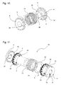
- FIG. 10 shows in a perspective exploded view another way how the toothed disks 4 can be assembled with the flow tube 5.
- the flow tube 5 is divided, so that it can be put together in a defined position in which the teeth of the two toothed disks are aligned as desired. In the example, this is achieved, as in a jaw coupling, by claws 35, which engage in recesses 36 on the opposite part.
- the slots 34 in the toothed disks 4 and the slot 6 in the flow tube are visible.
- a coil 13 is drawn in to illustrate that even in this embodiment, a prefabricated coil 13 can be used.
- FIG. 11 shows an exploded perspective view of a stator pole unit 18. This can be mounted practically in the order from left to right in the figure.
- a phase cover 8 has axial holding projections 10, with which it engages between the teeth 33 of an adjacent toothed disc 4.
- In a central bore of the phase cap 8 has radially inwardly projecting guide extensions 31, with which he later in grooves 17 (FIG. FIG. 12 ) a stator axis 16 ( FIG. 12 ) and thereby holds the phase cover and thus the toothed disc 4 in a defined angular position on the stator axis.
- a flow tube 5 is, for example, according to the above with reference to FIG. 1 variant described, inserted into the toothed disc 4, so it with his in the FIG.
- a coil 13 can be pushed onto the flow tube 5.
- the connection conductors of the coil 13 are denoted by 14.
- a spacer 15 has a radially extending slot, which serves to lead the connecting conductor 14 from the innermost position of the coil 13 to the outside.
- the stator pole unit 18 is completed.
- the toothed disks 4 advantageously have a radial slot 34 in order to avoid a ring closure.
- the phase carrier 9 has radially extending grooves 12 for the implementation of conductors and axially projecting positioning pins 11, whose function is described below with reference to FIG. 12 is explained.
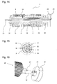
- FIG. 12 shows a stator 1 in an exploded perspective view, wherein two stator pole units 18 are already mounted on the stator axis 16, the third stator pole unit 18 but not yet.
- the stator axis 16 has at its periphery longitudinal grooves 17 and in the center a longitudinal bore 32.
- a contact ring 19 can be seen, which is intended to connect three winding ends of the coils 13 to each other to form a star point.
- the contact ring is fixed by means of the positioning pin 11 on the phase carrier 9.
- a plug-in contact unit 20 is shown, which comprises three plug contacts 21, which are to be connected to guided in the longitudinal grooves 17 of the stator axis conductors.
- FIG. 13 shows in a perspective view of a finished assembled stator 1. This is later potted with a potting compound, so that fixes all its components in the position shown and also protected against moisture and dirt.
- potting compound for example, polyurethane (PUR) or an epoxy resin (EP) may be.
- PUR polyurethane
- EP epoxy resin
- FIG. 14 shows a simplified longitudinal section through the stator 1, which is particularly clearly seen as conductors 23 for the supply and control of the transverse flux machine through the bore 32 in the stator 16 to a plugged into the right in the figure end of the stator 16 control unit 22nd lead and connected there with plug contacts 21.
- Leading conductor 14 leads from the control unit 22 to the three coils 13.
- a bearing 30 designed in the example as a ball bearing is arranged in each case. On the outer rings of these bearings 30 is supported in the finished assembled machine, the rotor 2 ( FIG. 15 ).
- FIG. 15 shows a cross section through the transverse flux machine, wherein from the inside to the outside through the central bore 32 of the stator 16 guided conductor 23 and arranged in the longitudinal grooves 17 of the stator 16 connecting conductor 14 can be seen.
- the bearing 30 carries the outer rotor 2, which is shown only schematically in this figure.
- FIG. 16 is shown in a perspective exploded view, the end of the stator 16, the right protrudes from a rotor pole unit 29.
- the figure illustrates how the control unit 22 can be pushed onto the stator axis 16 and connected by means of the plug contacts 21 and 24.
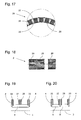
- FIG. 17 shows a section of a rotor pole unit in a cross-sectional view 29.
- a relatively thin-walled rotor carrier 26 receives on its periphery rotor magnets 25, which are constructed as permanent magnets and preferably as a layered body. The individual layers can be connected to each other, for example, by gluing or riveting.
- the rotor carrier 26 At the locations indicated by 28, the rotor carrier 26 on the outside recesses, whereby the wall is very thin at these points, so that the air gap between the rotor magnet 25 and the yokes is as thin as possible.
- a potting compound 27 can be seen, which may consist of the example mentioned in connection with the stator 1 potting compound of PUR or EP.
- FIG. 18 makes it clear how several, in the example three rotor pole units 29 can be arranged one behind the other and connected to a rotor 2.
- the rotor 2 may outside a jacket tube (not shown), for example made of aluminum. By this jacket tube and in particular the potting compound all components of the rotor 2 are protected against corrosion.
- stator pole units 18 and the rotor pole units 29 make it possible to assemble a motor as needed, by phasing strands together practically at will.
- the transversal flux machine described can be operated both as a motor and as a generator.
- FIGS. 19 and 20 show two further embodiments of the construction of the yokes of the stator of an embodiment of the inventive transverse flux machine.
- a middle plate 37 By inserting a middle plate 37, the effective number of teeth can be doubled. Instead of, for example, six individual phases (with appropriate control), a higher power is achieved with only three rotor phases.
- the offset by half a tooth width is realized in the middle plate 37. That is, the two outer discs 4 are arranged in parallel with identically aligned teeth 33, while the teeth 38 of the central disc 37 are offset by half the tooth width.
- the magnetic flux runs in each case from an outer disk 4 (north pole) to the middle disk (south pole) and back over the river pipe.
- the rotor magnets 25 can be better used.
- the rotor magnets 25 are hardly flowed through in the middle. With the extended phase, the rotor magnets 25 can be better utilized. In addition, the losses in the flow tube 5 decrease due to the shorter return flow path. With insignificantly more iron for the middle disc 37 with the same magnetic mass and less copper for the coils, the performance can be increased.
- the described arrangement of a middle plate 37 causes in operation of the transverse flux machine as a motor that this comes later into saturation and thus has more torque. When operating the transverse flux machine as a generator, the center plate 37 causes almost a doubling of the generated current. The very expensive magnetic mass of the rotor magnets 25 can be used more efficiently with the middle plate 37.
- FIG. 19 shows the construction with a single flow tube 5 per phase while FIG. 20 an embodiment with two separate flow tubes 5, 5 'per phase illustrated. Depending on the desired effect, the two windings per phase can be connected in parallel or in series.
Landscapes
- Engineering & Computer Science (AREA)
- Power Engineering (AREA)
- Iron Core Of Rotating Electric Machines (AREA)
- Manufacture Of Motors, Generators (AREA)
- Linear Motors (AREA)
Claims (9)
- Machine à flux transverse ayant au moins une unité polaire (29) extérieure du rotor et au moins une unité polaire (18) intérieure du stator agencée sur un axe de stator (16) et comprenant une bobine (13) agencée coaxialement à l'axe longitudinal (3) de la machine ainsi qu'un noyau de stator composé d'un tube de flux (5) agencé dans la bobine (13) et de disques dentés (4) agencés aux deux extrémités du tube de flux (5) et ayant des dents (33) circonférentielles radialement orientées, étant précisé que des moyens (8, 9, 10, 35, 36) pour la fixation géométrique de la position angulaire réciproque des disques dentés (4) et/ou des disques dentés (4) par rapport à l'axe de stator (16) sont pourvus, caractérisée en ce que le tube de flux est divisé en direction transversale, que chaque disque denté (4) est fixé à une partie respective du tube de flux et que les moyens pour la fixation géométrique de la position angulaire réciproque des disques dentés (4) sont réalisés sous la forme d'éléments à engagement géométrique (35, 36) agissant entre les deux parties du tube de flux (5).
- Machine à flux transverse selon la revendication 1, caractérisée en ce que les moyens de fixation géométrique de la position angulaire réciproque des disques dentés (4) sont réalisés sous la forme d'éléments à engagement géométrique agissant entre les disques dentés (4) et le tube de flux (5).
- Machine à flux transverse selon l'une des revendications précédentes, caractérisée en ce que les moyens de fixation géométrique de la position angulaire des disques dentés (4) par rapport à l'axe de stator sont constitués de corps annulaires (8, 9) ayant au moins une saillie de retenue s'étendant en direction axiale qui s'engage entre les dents (33) et au moins une saillie de guidage (31) s'étendant radialement vers l'intérieur qui s'engage dans une rainure longitudinale (17) de l'axe de stator (16).
- Machine à flux transverse selon l'une des revendications précédentes, caractérisée en ce que les disques dentés (4) présentent au moins une fente (34) orientée en direction radiale.
- Machine à flux transverse selon l'une des revendications précédentes, caractérisée en ce que le tube de flux (5) présente au moins une fente (6) orientée en direction radiale.
- Machine à flux transverse selon la revendication 5, caractérisée en ce que la fente (6) dans le tube de flux est agencée à un angle par rapport à l'axe longitudinal (3) de la machine.
- Machine à flux transverse selon l'une des revendications précédentes, caractérisée en ce que les disques dentés (4) sont composés de couches orientées perpendiculairement à l'axe longitudinal (3) de la machine.
- Machine à flux transverse selon l'une des revendications précédentes, caractérisée en ce qu'une unité de commande (22) est agencée sur l'axe de stator (16).
- Machine à flux transverse selon l'une des revendications précédentes, caractérisée en ce qu'entre les deux disques dentés (4) est agencé un disque denté supplémentaire (37) ayant des dents (38) circonférentielles radialement orientées, les dents (38) dudit disque denté (37) supplémentaire étant décalées d'une demi-largeur de dent en direction circonférentielle par rapport aux dents (33) des deux disques dentés (4).
Priority Applications (1)
| Application Number | Priority Date | Filing Date | Title |
|---|---|---|---|
| EP11802712.7A EP2656484B1 (fr) | 2010-12-20 | 2011-12-20 | Machine a flux transversal |
Applications Claiming Priority (3)
| Application Number | Priority Date | Filing Date | Title |
|---|---|---|---|
| EP10195843A EP2466723A1 (fr) | 2010-12-20 | 2010-12-20 | Machine à flux transversal |
| EP11802712.7A EP2656484B1 (fr) | 2010-12-20 | 2011-12-20 | Machine a flux transversal |
| PCT/EP2011/073349 WO2012084907A2 (fr) | 2010-12-20 | 2011-12-20 | Machine à flux transversal |
Publications (2)
| Publication Number | Publication Date |
|---|---|
| EP2656484A2 EP2656484A2 (fr) | 2013-10-30 |
| EP2656484B1 true EP2656484B1 (fr) | 2015-02-11 |
Family
ID=44276045
Family Applications (2)
| Application Number | Title | Priority Date | Filing Date |
|---|---|---|---|
| EP10195843A Withdrawn EP2466723A1 (fr) | 2010-12-20 | 2010-12-20 | Machine à flux transversal |
| EP11802712.7A Not-in-force EP2656484B1 (fr) | 2010-12-20 | 2011-12-20 | Machine a flux transversal |
Family Applications Before (1)
| Application Number | Title | Priority Date | Filing Date |
|---|---|---|---|
| EP10195843A Withdrawn EP2466723A1 (fr) | 2010-12-20 | 2010-12-20 | Machine à flux transversal |
Country Status (2)
| Country | Link |
|---|---|
| EP (2) | EP2466723A1 (fr) |
| WO (1) | WO2012084907A2 (fr) |
Families Citing this family (3)
| Publication number | Priority date | Publication date | Assignee | Title |
|---|---|---|---|---|
| TWM443982U (en) * | 2012-06-28 | 2012-12-21 | Leicong Ind Company Ltd | Motor assembly structure |
| CN110829631B (zh) * | 2018-08-10 | 2022-04-22 | 广东威灵电机制造有限公司 | 电机定子和电机 |
| JP7223233B2 (ja) * | 2020-05-11 | 2023-02-16 | ダイキン工業株式会社 | モータ |
Family Cites Families (13)
| Publication number | Priority date | Publication date | Assignee | Title |
|---|---|---|---|---|
| DE3224466A1 (de) * | 1982-06-30 | 1984-01-05 | Siemens AG, 1000 Berlin und 8000 München | Spulenkoerper |
| US4987331A (en) * | 1989-03-06 | 1991-01-22 | Alex Horng | Non-brush D.C. motor with an improved stator |
| DE59904085D1 (de) | 1998-11-27 | 2003-02-27 | Bombardier Transp Gmbh | Ein- oder mehrphasige Transversalflussmaschine |
| TW434980B (en) * | 1999-03-16 | 2001-05-16 | Sunonwealth Electr Mach Ind Co | Brushless DC motor and its stator |
| TW440106U (en) * | 1999-08-20 | 2001-06-07 | Attend Industry Co Ltd | Improved structure of wheeling generator |
| DE29919904U1 (de) * | 1999-11-12 | 2000-02-03 | Sunonwealth Electric Machine Industry Co., Ltd., Kaohsiung | Bürstenloser Gleichstrommotor mit Drehzahlverminderung |
| TWI221696B (en) * | 2003-08-26 | 2004-10-01 | Delta Electronics Inc | Motor stator, main-body structure of motor stator, and manufacturing method thereof |
| TWI290409B (en) * | 2004-04-14 | 2007-11-21 | Delta Electronics Inc | Composite stator structure of motor |
| EP1632427A1 (fr) * | 2004-09-02 | 2006-03-08 | Lee Chi Enterprises Company Ltd. | Moyeu générateur à noyau de fer enroulé |
| DE102004057101B4 (de) * | 2004-11-26 | 2006-08-24 | Voith Turbo Gmbh & Co. Kg | Einseitige Synchronmaschine mit transversaler Flussführung |
| DE102005017934A1 (de) * | 2005-04-18 | 2006-10-19 | Asia Vital Component Co., Ltd., Hsin Chuan | Motorstator |
| CA2608470C (fr) | 2005-06-29 | 2009-08-18 | Eocycle Technologies Inc. | Machine electrique a flux transversal avec stator a noyau segmente |
| JP2007049844A (ja) * | 2005-08-11 | 2007-02-22 | Shinano Kenshi Co Ltd | アウターロータ型モータ |
-
2010
- 2010-12-20 EP EP10195843A patent/EP2466723A1/fr not_active Withdrawn
-
2011
- 2011-12-20 EP EP11802712.7A patent/EP2656484B1/fr not_active Not-in-force
- 2011-12-20 WO PCT/EP2011/073349 patent/WO2012084907A2/fr not_active Ceased
Also Published As
| Publication number | Publication date |
|---|---|
| WO2012084907A3 (fr) | 2013-08-15 |
| EP2466723A1 (fr) | 2012-06-20 |
| EP2656484A2 (fr) | 2013-10-30 |
| WO2012084907A2 (fr) | 2012-06-28 |
Similar Documents
| Publication | Publication Date | Title |
|---|---|---|
| EP1495527B1 (fr) | Machine electrique, notamment moteur excite par aimant permanent | |
| DE19802784C2 (de) | Synchronmaschine, insbesondere Generator für ein Kraftfahrzeug | |
| DE112015002516B4 (de) | Elektrische Rotationsmaschine und Herstellungsverfahren für eine elektrische Rotationsmaschine | |
| DE102010018145B4 (de) | Dynamoelektrische Maschine der Klauenpolbauart | |
| CH695810A5 (de) | Statorkernanordnung. | |
| DE112014007129T5 (de) | Statorkern für eine elektrische Rotationsmaschine, elektrische Rotationsmaschine und Verfahren zur Herstellung einer elektrischen Rotationsmaschine | |
| EP1428306B1 (fr) | Moteur electrique a commutation electronique a bobines paralleles a l'axe | |
| EP1657801A2 (fr) | Rotor pour une machine électrique et procédé de fabrication d'un rotor | |
| DE102010032764A1 (de) | Elektrische Maschine und Stator für dieselbe | |
| DE4423840A1 (de) | Radialmagnetmotor | |
| WO2018054599A1 (fr) | Unité d'entraînement électrique munie d'une douille de refroidissement | |
| DE202004016534U1 (de) | Elektromotor | |
| DE102007013738B4 (de) | Elektrische Maschine mit Klauenpolstator | |
| EP2652862B1 (fr) | Élément de machine destiné à une machine électrique | |
| WO2012084907A2 (fr) | Machine à flux transversal | |
| DE4138014C1 (en) | Electromechanical power converter in rotary or linear form - has permanent magnets assembled in rotor driven by AC stator winding with pole elements | |
| DE102015222271A1 (de) | Rotor sowie elektrische Maschine | |
| EP1588470B1 (fr) | Machine electrique a aimant permanent | |
| WO2018197133A1 (fr) | Stator segmenté pour moteur électrique du type à rotor interne | |
| DE202004002372U1 (de) | Elektromotor | |
| DE102005053042A1 (de) | Linearmotor mit kreisrunden Ringspulen | |
| EP2188881B1 (fr) | Moteur électrique et procédé de fabrication d'un moteur électrique | |
| DE10056875A1 (de) | Rotor für eine elektrische Maschine | |
| DE202022104369U1 (de) | Elektromotor mit speziellem, leicht bewickelbaren Statorkörper | |
| EP1928075A2 (fr) | Moteur électrique sans balais |
Legal Events
| Date | Code | Title | Description |
|---|---|---|---|
| PUAI | Public reference made under article 153(3) epc to a published international application that has entered the european phase |
Free format text: ORIGINAL CODE: 0009012 |
|
| 17P | Request for examination filed |
Effective date: 20130704 |
|
| AK | Designated contracting states |
Kind code of ref document: A2 Designated state(s): AL AT BE BG CH CY CZ DE DK EE ES FI FR GB GR HR HU IE IS IT LI LT LU LV MC MK MT NL NO PL PT RO RS SE SI SK SM TR |
|
| 17Q | First examination report despatched |
Effective date: 20140424 |
|
| DAX | Request for extension of the european patent (deleted) | ||
| GRAP | Despatch of communication of intention to grant a patent |
Free format text: ORIGINAL CODE: EPIDOSNIGR1 |
|
| INTG | Intention to grant announced |
Effective date: 20140804 |
|
| GRAS | Grant fee paid |
Free format text: ORIGINAL CODE: EPIDOSNIGR3 |
|
| GRAA | (expected) grant |
Free format text: ORIGINAL CODE: 0009210 |
|
| RAP1 | Party data changed (applicant data changed or rights of an application transferred) |
Owner name: MATHYS, REINHOLD |
|
| AK | Designated contracting states |
Kind code of ref document: B1 Designated state(s): AL AT BE BG CH CY CZ DE DK EE ES FI FR GB GR HR HU IE IS IT LI LT LU LV MC MK MT NL NO PL PT RO RS SE SI SK SM TR |
|
| REG | Reference to a national code |
Ref country code: GB Ref legal event code: FG4D Free format text: NOT ENGLISH |
|
| REG | Reference to a national code |
Ref country code: CH Ref legal event code: EP |
|
| REG | Reference to a national code |
Ref country code: IE Ref legal event code: FG4D Free format text: LANGUAGE OF EP DOCUMENT: GERMAN |
|
| REG | Reference to a national code |
Ref country code: AT Ref legal event code: REF Ref document number: 710188 Country of ref document: AT Kind code of ref document: T Effective date: 20150315 |
|
| REG | Reference to a national code |
Ref country code: DE Ref legal event code: R096 Ref document number: 502011005870 Country of ref document: DE Effective date: 20150326 |
|
| REG | Reference to a national code |
Ref country code: CH Ref legal event code: NV Representative=s name: AMMANN PATENTANWAELTE AG BERN, CH |
|
| REG | Reference to a national code |
Ref country code: NL Ref legal event code: VDEP Effective date: 20150211 |
|
| REG | Reference to a national code |
Ref country code: LT Ref legal event code: MG4D |
|
| PG25 | Lapsed in a contracting state [announced via postgrant information from national office to epo] |
Ref country code: ES Free format text: LAPSE BECAUSE OF FAILURE TO SUBMIT A TRANSLATION OF THE DESCRIPTION OR TO PAY THE FEE WITHIN THE PRESCRIBED TIME-LIMIT Effective date: 20150211 Ref country code: NO Free format text: LAPSE BECAUSE OF FAILURE TO SUBMIT A TRANSLATION OF THE DESCRIPTION OR TO PAY THE FEE WITHIN THE PRESCRIBED TIME-LIMIT Effective date: 20150511 Ref country code: FI Free format text: LAPSE BECAUSE OF FAILURE TO SUBMIT A TRANSLATION OF THE DESCRIPTION OR TO PAY THE FEE WITHIN THE PRESCRIBED TIME-LIMIT Effective date: 20150211 Ref country code: SE Free format text: LAPSE BECAUSE OF FAILURE TO SUBMIT A TRANSLATION OF THE DESCRIPTION OR TO PAY THE FEE WITHIN THE PRESCRIBED TIME-LIMIT Effective date: 20150211 Ref country code: LT Free format text: LAPSE BECAUSE OF FAILURE TO SUBMIT A TRANSLATION OF THE DESCRIPTION OR TO PAY THE FEE WITHIN THE PRESCRIBED TIME-LIMIT Effective date: 20150211 Ref country code: HR Free format text: LAPSE BECAUSE OF FAILURE TO SUBMIT A TRANSLATION OF THE DESCRIPTION OR TO PAY THE FEE WITHIN THE PRESCRIBED TIME-LIMIT Effective date: 20150211 |
|
| PG25 | Lapsed in a contracting state [announced via postgrant information from national office to epo] |
Ref country code: IS Free format text: LAPSE BECAUSE OF FAILURE TO SUBMIT A TRANSLATION OF THE DESCRIPTION OR TO PAY THE FEE WITHIN THE PRESCRIBED TIME-LIMIT Effective date: 20150611 Ref country code: LV Free format text: LAPSE BECAUSE OF FAILURE TO SUBMIT A TRANSLATION OF THE DESCRIPTION OR TO PAY THE FEE WITHIN THE PRESCRIBED TIME-LIMIT Effective date: 20150211 Ref country code: RS Free format text: LAPSE BECAUSE OF FAILURE TO SUBMIT A TRANSLATION OF THE DESCRIPTION OR TO PAY THE FEE WITHIN THE PRESCRIBED TIME-LIMIT Effective date: 20150211 Ref country code: NL Free format text: LAPSE BECAUSE OF FAILURE TO SUBMIT A TRANSLATION OF THE DESCRIPTION OR TO PAY THE FEE WITHIN THE PRESCRIBED TIME-LIMIT Effective date: 20150211 Ref country code: GR Free format text: LAPSE BECAUSE OF FAILURE TO SUBMIT A TRANSLATION OF THE DESCRIPTION OR TO PAY THE FEE WITHIN THE PRESCRIBED TIME-LIMIT Effective date: 20150512 |
|
| PG25 | Lapsed in a contracting state [announced via postgrant information from national office to epo] |
Ref country code: EE Free format text: LAPSE BECAUSE OF FAILURE TO SUBMIT A TRANSLATION OF THE DESCRIPTION OR TO PAY THE FEE WITHIN THE PRESCRIBED TIME-LIMIT Effective date: 20150211 Ref country code: RO Free format text: LAPSE BECAUSE OF FAILURE TO SUBMIT A TRANSLATION OF THE DESCRIPTION OR TO PAY THE FEE WITHIN THE PRESCRIBED TIME-LIMIT Effective date: 20150211 Ref country code: CZ Free format text: LAPSE BECAUSE OF FAILURE TO SUBMIT A TRANSLATION OF THE DESCRIPTION OR TO PAY THE FEE WITHIN THE PRESCRIBED TIME-LIMIT Effective date: 20150211 Ref country code: SK Free format text: LAPSE BECAUSE OF FAILURE TO SUBMIT A TRANSLATION OF THE DESCRIPTION OR TO PAY THE FEE WITHIN THE PRESCRIBED TIME-LIMIT Effective date: 20150211 Ref country code: DK Free format text: LAPSE BECAUSE OF FAILURE TO SUBMIT A TRANSLATION OF THE DESCRIPTION OR TO PAY THE FEE WITHIN THE PRESCRIBED TIME-LIMIT Effective date: 20150211 |
|
| REG | Reference to a national code |
Ref country code: DE Ref legal event code: R097 Ref document number: 502011005870 Country of ref document: DE |
|
| PG25 | Lapsed in a contracting state [announced via postgrant information from national office to epo] |
Ref country code: PL Free format text: LAPSE BECAUSE OF FAILURE TO SUBMIT A TRANSLATION OF THE DESCRIPTION OR TO PAY THE FEE WITHIN THE PRESCRIBED TIME-LIMIT Effective date: 20150211 |
|
| PLBE | No opposition filed within time limit |
Free format text: ORIGINAL CODE: 0009261 |
|
| STAA | Information on the status of an ep patent application or granted ep patent |
Free format text: STATUS: NO OPPOSITION FILED WITHIN TIME LIMIT |
|
| PG25 | Lapsed in a contracting state [announced via postgrant information from national office to epo] |
Ref country code: IT Free format text: LAPSE BECAUSE OF FAILURE TO SUBMIT A TRANSLATION OF THE DESCRIPTION OR TO PAY THE FEE WITHIN THE PRESCRIBED TIME-LIMIT Effective date: 20150211 |
|
| 26N | No opposition filed |
Effective date: 20151112 |
|
| PG25 | Lapsed in a contracting state [announced via postgrant information from national office to epo] |
Ref country code: SI Free format text: LAPSE BECAUSE OF FAILURE TO SUBMIT A TRANSLATION OF THE DESCRIPTION OR TO PAY THE FEE WITHIN THE PRESCRIBED TIME-LIMIT Effective date: 20150211 |
|
| PG25 | Lapsed in a contracting state [announced via postgrant information from national office to epo] |
Ref country code: BE Free format text: LAPSE BECAUSE OF NON-PAYMENT OF DUE FEES Effective date: 20151231 |
|
| REG | Reference to a national code |
Ref country code: DE Ref legal event code: R119 Ref document number: 502011005870 Country of ref document: DE |
|
| PG25 | Lapsed in a contracting state [announced via postgrant information from national office to epo] |
Ref country code: LU Free format text: LAPSE BECAUSE OF FAILURE TO SUBMIT A TRANSLATION OF THE DESCRIPTION OR TO PAY THE FEE WITHIN THE PRESCRIBED TIME-LIMIT Effective date: 20151220 Ref country code: MC Free format text: LAPSE BECAUSE OF FAILURE TO SUBMIT A TRANSLATION OF THE DESCRIPTION OR TO PAY THE FEE WITHIN THE PRESCRIBED TIME-LIMIT Effective date: 20150211 |
|
| REG | Reference to a national code |
Ref country code: CH Ref legal event code: PL |
|
| GBPC | Gb: european patent ceased through non-payment of renewal fee |
Effective date: 20151220 |
|
| REG | Reference to a national code |
Ref country code: IE Ref legal event code: MM4A |
|
| REG | Reference to a national code |
Ref country code: FR Ref legal event code: ST Effective date: 20160831 |
|
| PG25 | Lapsed in a contracting state [announced via postgrant information from national office to epo] |
Ref country code: GB Free format text: LAPSE BECAUSE OF NON-PAYMENT OF DUE FEES Effective date: 20151220 Ref country code: CH Free format text: LAPSE BECAUSE OF NON-PAYMENT OF DUE FEES Effective date: 20151231 Ref country code: LI Free format text: LAPSE BECAUSE OF NON-PAYMENT OF DUE FEES Effective date: 20151231 Ref country code: DE Free format text: LAPSE BECAUSE OF NON-PAYMENT OF DUE FEES Effective date: 20160701 Ref country code: IE Free format text: LAPSE BECAUSE OF NON-PAYMENT OF DUE FEES Effective date: 20151220 |
|
| PG25 | Lapsed in a contracting state [announced via postgrant information from national office to epo] |
Ref country code: FR Free format text: LAPSE BECAUSE OF NON-PAYMENT OF DUE FEES Effective date: 20151231 |
|
| PG25 | Lapsed in a contracting state [announced via postgrant information from national office to epo] |
Ref country code: SM Free format text: LAPSE BECAUSE OF FAILURE TO SUBMIT A TRANSLATION OF THE DESCRIPTION OR TO PAY THE FEE WITHIN THE PRESCRIBED TIME-LIMIT Effective date: 20150211 Ref country code: BG Free format text: LAPSE BECAUSE OF FAILURE TO SUBMIT A TRANSLATION OF THE DESCRIPTION OR TO PAY THE FEE WITHIN THE PRESCRIBED TIME-LIMIT Effective date: 20150211 Ref country code: HU Free format text: LAPSE BECAUSE OF FAILURE TO SUBMIT A TRANSLATION OF THE DESCRIPTION OR TO PAY THE FEE WITHIN THE PRESCRIBED TIME-LIMIT; INVALID AB INITIO Effective date: 20111220 |
|
| PG25 | Lapsed in a contracting state [announced via postgrant information from national office to epo] |
Ref country code: CY Free format text: LAPSE BECAUSE OF FAILURE TO SUBMIT A TRANSLATION OF THE DESCRIPTION OR TO PAY THE FEE WITHIN THE PRESCRIBED TIME-LIMIT Effective date: 20150211 |
|
| PG25 | Lapsed in a contracting state [announced via postgrant information from national office to epo] |
Ref country code: MT Free format text: LAPSE BECAUSE OF FAILURE TO SUBMIT A TRANSLATION OF THE DESCRIPTION OR TO PAY THE FEE WITHIN THE PRESCRIBED TIME-LIMIT Effective date: 20150211 |
|
| REG | Reference to a national code |
Ref country code: AT Ref legal event code: MM01 Ref document number: 710188 Country of ref document: AT Kind code of ref document: T Effective date: 20161220 |
|
| PG25 | Lapsed in a contracting state [announced via postgrant information from national office to epo] |
Ref country code: AT Free format text: LAPSE BECAUSE OF NON-PAYMENT OF DUE FEES Effective date: 20161220 |
|
| PG25 | Lapsed in a contracting state [announced via postgrant information from national office to epo] |
Ref country code: PT Free format text: LAPSE BECAUSE OF FAILURE TO SUBMIT A TRANSLATION OF THE DESCRIPTION OR TO PAY THE FEE WITHIN THE PRESCRIBED TIME-LIMIT Effective date: 20150211 Ref country code: MK Free format text: LAPSE BECAUSE OF FAILURE TO SUBMIT A TRANSLATION OF THE DESCRIPTION OR TO PAY THE FEE WITHIN THE PRESCRIBED TIME-LIMIT Effective date: 20150211 |
|
| PG25 | Lapsed in a contracting state [announced via postgrant information from national office to epo] |
Ref country code: TR Free format text: LAPSE BECAUSE OF FAILURE TO SUBMIT A TRANSLATION OF THE DESCRIPTION OR TO PAY THE FEE WITHIN THE PRESCRIBED TIME-LIMIT Effective date: 20150211 Ref country code: AL Free format text: LAPSE BECAUSE OF FAILURE TO SUBMIT A TRANSLATION OF THE DESCRIPTION OR TO PAY THE FEE WITHIN THE PRESCRIBED TIME-LIMIT Effective date: 20150211 |