EP2656633B1 - Dispositif et procédé pour le calcul de signaux de haut-parleurs pour une pluralité de haut-parleurs, utilisant une temporisation dans la gamme de fréquence - Google Patents
Dispositif et procédé pour le calcul de signaux de haut-parleurs pour une pluralité de haut-parleurs, utilisant une temporisation dans la gamme de fréquence Download PDFInfo
- Publication number
- EP2656633B1 EP2656633B1 EP12816679.0A EP12816679A EP2656633B1 EP 2656633 B1 EP2656633 B1 EP 2656633B1 EP 12816679 A EP12816679 A EP 12816679A EP 2656633 B1 EP2656633 B1 EP 2656633B1
- Authority
- EP
- European Patent Office
- Prior art keywords
- loudspeaker
- short
- delay
- filter
- stage
- Prior art date
- Legal status (The legal status is an assumption and is not a legal conclusion. Google has not performed a legal analysis and makes no representation as to the accuracy of the status listed.)
- Active
Links
Images




Classifications
-
- G—PHYSICS
- G10—MUSICAL INSTRUMENTS; ACOUSTICS
- G10L—SPEECH ANALYSIS TECHNIQUES OR SPEECH SYNTHESIS; SPEECH RECOGNITION; SPEECH OR VOICE PROCESSING TECHNIQUES; SPEECH OR AUDIO CODING OR DECODING
- G10L19/00—Speech or audio signals analysis-synthesis techniques for redundancy reduction, e.g. in vocoders; Coding or decoding of speech or audio signals, using source filter models or psychoacoustic analysis
- G10L19/04—Speech or audio signals analysis-synthesis techniques for redundancy reduction, e.g. in vocoders; Coding or decoding of speech or audio signals, using source filter models or psychoacoustic analysis using predictive techniques
- G10L19/26—Pre-filtering or post-filtering
-
- H—ELECTRICITY
- H04—ELECTRIC COMMUNICATION TECHNIQUE
- H04R—LOUDSPEAKERS, MICROPHONES, GRAMOPHONE PICK-UPS OR LIKE ACOUSTIC ELECTROMECHANICAL TRANSDUCERS; ELECTRIC HEARING AIDS; PUBLIC ADDRESS SYSTEMS
- H04R29/00—Monitoring arrangements; Testing arrangements
- H04R29/001—Monitoring arrangements; Testing arrangements for loudspeakers
-
- H—ELECTRICITY
- H04—ELECTRIC COMMUNICATION TECHNIQUE
- H04R—LOUDSPEAKERS, MICROPHONES, GRAMOPHONE PICK-UPS OR LIKE ACOUSTIC ELECTROMECHANICAL TRANSDUCERS; ELECTRIC HEARING AIDS; PUBLIC ADDRESS SYSTEMS
- H04R3/00—Circuits for transducers
- H04R3/12—Circuits for transducers for distributing signals to two or more loudspeakers
-
- H—ELECTRICITY
- H04—ELECTRIC COMMUNICATION TECHNIQUE
- H04R—LOUDSPEAKERS, MICROPHONES, GRAMOPHONE PICK-UPS OR LIKE ACOUSTIC ELECTROMECHANICAL TRANSDUCERS; ELECTRIC HEARING AIDS; PUBLIC ADDRESS SYSTEMS
- H04R2430/00—Signal processing covered by H04R, not provided for in its groups
- H04R2430/03—Synergistic effects of band splitting and sub-band processing
-
- H—ELECTRICITY
- H04—ELECTRIC COMMUNICATION TECHNIQUE
- H04S—STEREOPHONIC SYSTEMS
- H04S2420/00—Techniques used stereophonic systems covered by H04S but not provided for in its groups
- H04S2420/07—Synergistic effects of band splitting and sub-band processing
-
- H—ELECTRICITY
- H04—ELECTRIC COMMUNICATION TECHNIQUE
- H04S—STEREOPHONIC SYSTEMS
- H04S2420/00—Techniques used stereophonic systems covered by H04S but not provided for in its groups
- H04S2420/13—Application of wave-field synthesis in stereophonic audio systems
Definitions
- the present invention relates to an apparatus and a method for calculating loudspeaker signals for a plurality of loudspeakers using frequency-domain filtering, such as a wave-field synthesis renderer device and a method of operating such a device.
- WFS Wave Field Synthesis
- WFS The basic idea of WFS is based on the application of Huygens' principle of wave theory: every point, which is detected by a wave, is the starting point of an elementary wave, which spreads in a spherical or circular manner.
- Applied to the acoustics can be simulated by a large number of speakers, which are arranged side by side (a so-called speaker array), any sound field.
- the audio signal of each speaker is generated by the application of a so-called. WFS operator from the audio signal of the source.
- the WFS operator corresponds to an amplitude scaling and a time delay of the input signal.
- the application of this amplitude scaling and time delay is hereafter referred to as Scale & Delay.
- a time delay and amplitude scaling can be applied to the audio signal of each loudspeaker so that the radiated sound fields of the individual loudspeakers are properly superimposed.
- the contribution to each speaker is calculated separately for each source and the resulting signals added together. If the sources to be reproduced are in a room with reflective walls, reflections must also be reproduced as additional sources via the loudspeaker array. The cost of the calculation therefore depends heavily on the number of sound sources, the reflection characteristics of the recording room and the number of speakers.
- the advantage of this technique is in particular that a natural spatial sound impression over a large area of the playback room is possible.
- the direction and distance of sound sources are reproduced very accurately.
- virtual sound sources can even be positioned between the real speaker array and the listener.
- wave field synthesis provides good, if the assumed assumptions in theory, such as ideal speaker characteristics, regular, gapless speaker arrays or free field conditions for sound propagation are at least approximately fulfilled. In practice, however, these conditions are often violated, for. B. by incomplete speaker arrays or a significant influence of room acoustics.
- An environmental condition can be described by the impulse response of the environment.
- the space compensation using wavefield synthesis would be to first determine the reflection of that wall to determine when a sound signal reflected from the wall will return to the loudspeaker and what amplitude this reflected sound signal will be Has. If the reflection from this wall is undesirable, then with the wave field synthesis it is possible to eliminate the reflection from this wall by impressing the loudspeaker with a signal of opposite amplitude to the reflection signal in addition to the original audio signal, so that the traveling compensating wave is the Reflectance wave extinguished, so that the reflection from this wall in the environment that is considered, is eliminated. This can be done by first computing the impulse response of the environment and determining the nature and position of the wall based on the impulse response of that environment. In this case, the sound reflected by the wall is represented by an additional WFS sound source, a so-called mirror sound source, whose signal is generated by filtering and delay from the original source signal.
- Wave field synthesis thus allows a correct mapping of virtual sound sources over a large playback area. At the same time it offers the sound engineer and sound engineer new technical and creative potential in the creation of even complex soundscapes.
- Wave field synthesis as developed at the TU Delft in the late 1980s, represents a holographic approach to sound reproduction. The basis for this is the Kirchhoff-Helmholtz integral. This states that any sound fields within a closed volume are distributed by means of a distribution of monopoly and dipole sound sources (speaker arrays) can be created on the surface of this volume.
- a synthesis signal is calculated for each loudspeaker of the loudspeaker array, the synthesis signals being designed in amplitude and delay such that a wave resulting from the superimposition of the individual the sound wave present in the loudspeaker array will correspond to the wave that would result from the virtual source at the virtual position if that virtual source at the virtual position were a real source with a real position.
- multiple virtual sources exist at different virtual locations.
- the computation of the synthesis signals is performed for each virtual source at each virtual location, typically resulting in one virtual source in multiple speaker synthesis signals. Seen from a loudspeaker, this loudspeaker thus receives several synthesis signals, which go back to different virtual sources. A superimposition of these sources, which is possible due to the linear superposition principle, then gives the reproduced signal actually emitted by the speaker.
- the object of the present invention is to provide an efficient concept for calculating loudspeaker signals for a plurality of loudspeakers using audio sources.
- the present invention is advantageous in that it provides an efficient concept through the combination of an out-of-order stage, a memory, a memory access controller, a filter stage, a summer stage, and a re-transform stage, characterized in that the The number of round-trip transformation calculations need not be made for each individual audio source / speaker combination, but only for each individual audio source.
- the re-transformation need not be calculated for each individual audio-signal-speaker combination, but only for the number of speakers.
- the number of Hin-Transform calculations is equal to the number of audio sources and the number of reverse-transformation calculations is equal to the number of loudspeaker signals or loudspeakers to be driven when a loudspeaker signal drives a loudspeaker.
- the introduction of the delay in the frequency domain is achieved by a memory access control in an efficient manner by advantageously exploiting the feed used in the transformation based on a delay value for an audio signal / loudspeaker combination.
- the out-of-order stage provides a sequence of short-term spectra stored in memory for each audio signal.
- the memory access controller thus has access to a sequence of temporally successive short-term spectra.
- the short-term spectrum is selected from the sequence of short-term spectra that best matches the delay value provided by, for example, a wave field synthesis operator. For example, if the feed value in the calculation of the individual blocks of a short-term spectrum to the next short-term spectrum is 20 ms, and if the wave-field synthesis operator requires a delay of 100 ms, then this entire delay can easily be implemented by not having the most recent short-term spectrum in the memory for the audio / loudspeaker combination under consideration is used, but also stored fifth past spa time spectrum.
- the device according to the invention is already able to implement a delay solely on the basis of the stored short-term spectra in a certain grid, which is determined by the feed. If this grid is already sufficient for a particular application, no further action is required. However, if a finer delay control is needed, it can also be implemented in the frequency domain by using in the filtering stage to filter a particular short-term spectrum a filter whose impulse response has been manipulated with a certain number of zeros at the beginning of the filter impulse response. Thus, a finer delay granulation can be achieved, which does not take place now, as in the memory access control in periods according to the block feed, but now much finer in terms of a sampling period, ie the time interval between two samples.
- the delay can also be implemented in the filter stage by implementing the impulse response, which has already been supplemented with zeros, using a fractional delay filter.
- all the necessary delay values can be implemented in the frequency domain, that is to say between the Hin transformation and therut transformation, wherein the greatest proportion of the delay is achieved simply by a memory access control, in which case a granulation according to the block Feed is achieved or according to the time period corresponding to a block feed. If finer delays are needed, this finer delay is implemented by modifying the filter impulse response for each audio signal / speaker combination in the filter stage to insert zeros at the beginning of the impulse response.
- the present invention is particularly suitable for static sources because the static virtual sources also have static delay values for each audio-signal-speaker combination. Therefore, for every position of a virtual source the memory access control will be fixed.
- the impulse response for the particular loudspeaker audio signal combination in each individual block of the filter stage can be pre-set before the actual rendering algorithm is executed. For this purpose, the actually required for this audio signal speaker combination impulse response is changed so that a corresponding number of zeros at the beginning of the impulse response is inserted in order to achieve a finely resolved delay. Then this impulse response is transformed into the spectral range and stored there in a single filter. In the actual wave field synthesis rendering calculation, it is then always possible to resort to stored transfer functions of the individual filters in the individual filter blocks.
- a preferred wavefield synthesis renderer device or method for operating a wavefield synthesis renderer device comprises N virtual sound sources that provide sampling values for the source signals x 0 ... X N-1 , and a signal processing unit composed of the Source signals x 0 ... x N-1 Sampling values for M loudspeaker signals y 0 ... y M-1 generated, wherein in the signal processing unit for each source-speaker combination a filter spectrum is stored, each source signal x 0 ...
- x N-1 is transformed into the spectra with a plurality of FFT calculation blocks of block length L, the FFT calculation blocks having an overlap of length (LB) and a length B feed, multiplying each spectrum by the respective filter spectra of the same source is, from which the spectra are generated, the access to the spectra is such that the speakers each with a r predetermined delay corresponding to an integer multiple of the feed B, all spectra of the same speaker i are added, from which the spectra Q j are generated, and each spectrum Q j with an IFFT calculation block in the sampling values for the M loudspeaker signals y 0 ... y M-1 is transformed.
- the block-by-block shift of the individual spectra can be exploited to generate a delay of the loudspeaker signals y 0 ... Y M-1 by a targeted access to the spectra.
- the computational effort for this delay depends only on the targeted access to the spectra, so that no additional computing power is required for the introduction of delays, as long as the delay corresponds to an integer multiple of the feed B.
- the invention thus relates to the wave field synthesis of Richteten sound sources or sound sources with directional characteristics.
- WFS setups which consist of multiple virtual sources and a large number of speakers, the need to apply individual FIR filters for each combination of virtual source and loudspeaker often prevents easy implementation.
- the invention proposes an efficient processing structure based on time / frequency techniques.
- Combining the components of a fast convolution algorithm into the structure of a WFS rendering system allows the efficient reuse of operations and intermediate results, and thus a significant increase in efficiency.
- the potential acceleration increases with the number of virtual sources and speakers, significant savings are also made for moderate-size WFS assemblies.
- the performance gains are relatively consistent for a wide variety of parameter choices for the filter size and block delay value.
- the handling of time delays which is an inherent requirement of sound reproduction techniques, such as e.g. WFS requires a modification of the overlap-save technique. This is efficiently solved by partitioning the delay value and using frequency-domain delay lines or frequency-line-implemented delay lines.
- the invention is thus not limited to the processing of directional sound sources or directional sound sources in the WFS, but is also applicable to other processing tasks that use massive multi-channel filtering with optional time delays.
- the generation of the spectra takes place according to the overlap-save method.
- the overlap save method is a fast folding method.
- the input sequence x 0 ... x N-1 is decomposed into overlapping subsequences. From the formed periodic folding products (cyclic Convolution), then those parts are taken which agree with the aperiodic, fast convolution.
- the filter spectra are transformed by means of an FFT from time-discrete impulse responses.
- the filter spectra can be provided before the actual execution of the time-critical calculation steps, so that the calculation of the filter spectra does not influence the time-critical part of the calculation.
- each impulse response is preceded by a number of zeros in such a way that the loudspeakers are each actuated with a predetermined delay, which corresponds to the number of zeros.
- a predetermined delay which corresponds to the number of zeros.
- delays can be realized that do not correspond to an integer multiple of the feed B.
- the desired delay is divided into two parts: The first part is an integer multiple of the feed B, while the second part represents the rest. This second fraction is thus inevitably smaller than the feed B in the case of such a decomposition.
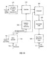
- Fig. 1a shows a device for calculating loudspeaker signals for a plurality of loudspeakers, which may for example be arranged at predetermined positions in a reproduction room, using a plurality of audio sources, wherein an audio source comprises an audio signal 10.
- the audio signals 10 are supplied to an out-transformation stage 100, which is designed to carry out a block-by-block transformation of each audio signal into a spectral range, so that a plurality of temporally consecutive short-time spectra are obtained for each audio signal.
- a memory 200 is provided, which is designed to store a number of temporally successive short-term spectra for each audio signal.
- each short-term spectrum of the plurality of short-term spectra may be assigned a time-increasing time value, and the memory then stores the temporally-consecutive short-term spectra for each audio signal in association with the time values.
- the short-term spectra in the memory do not have to be arranged in chronological succession here. Instead, the short-term spectra, for example, in a RAM memory at any point be stored as long as a memory contents table is present, which identifies which time value corresponds to which spectrum, and which spectrum belongs to which audio signal.
- the memory access controller is thus configured to access a specific short-term spectrum from the plurality of short-term spectra for a combination of loudspeaker and audio signal based on a delay value given for this audio-signal-loudspeaker combination.
- the determined short-term spectra determined by the memory access controller 600 are then applied to a filtering stage 300 for filtering the determined short-term spectra for combinations of audio signals and loudspeakers to perform filtering with a filter provided for the respective audio signal and loudspeaker combination for each Such combination of audio signal and speaker to obtain a sequence of filtered short-term spectra.
- the filtered short-term spectra are then supplied from the filter stage 300 to a summing stage 400 to sum the filtered short-term spectrum for a loudspeaker such that a summed short-term spectrum is obtained for each loudspeaker.
- the accumulated short-term spectra are then applied to a back-transformation stage 800 for block-wise back-transforming the summed short-term spectra for the loudspeakers to obtain the short-term spectra in a time range from which the loudspeaker signals can be determined.
- the loudspeaker signals are thus output from the back-transformation stage 800 at an output 12.
- the delay values 701 are provided by a Wave Field Synthesis Operator (WFS operator) 700 for each embodiment of the invention, in which the device is a wave field synthesis device, which is fed via an input 702 for each individual audio signal and loudspeaker combination and, depending on the loudspeaker positions, ie the positions in which the loudspeakers are arranged in the reproduction room, and which are supplied via an input 703, the delay values 701 are calculated. If the device is designed for a different application than for the wave field synthesis, so z. For example, for an Ambisonics implementation or the like, an element corresponding to the WFS operator 700 will also be present, which calculates delay values for individual loudspeaker signals or calculates delay values for individual audio signal loudspeaker combinations.
- WFS operator 700 Wave Field Synthesis Operator 700 for each embodiment of the invention, in which the device is a wave field synthesis device, which is fed via an input 702 for each individual audio signal and loudspeaker combination and, depending on the loudspeaker positions, ie the positions in
- the WFS operator 700 will calculate not only the delay values but also scaling values, which typically can also be considered in the filter stage 300 by a scaling factor. Thus, these can be achieved by scaling the filter coefficients used in filter stage 300 be taken into account without incurring additional calculation effort.
- the memory access controller 600 may therefore be configured in a particular implementation to obtain delay values for various audio signal and speaker combinations, and to calculate an access value to the memory for each combination, as further described with reference to FIG Fig. 1b is pictured. Accordingly, as also referring to Fig. 1b
- the filter stage 300 may be configured to obtain delay values for various combinations of audio signal and loudspeaker to calculate therefrom a number of zeros to be considered in the impulse responses for the individual audio signals / speaker combinations.
- the filter stage 300 is therefore configured to implement a finer granularity delay in multiples of the sample period while the memory access controller 600 is configured to provide, through efficient memory access, delays in the granularity of the feed B from the out-of-stage is applied to implement.
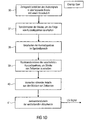
- FIG. 12 shows a sequence of functions performed by elements 700, 600, 300 of FIG Fig. 1a can be executed.
- the WFS operator 700 is configured to provide a delay value D as shown in step 20 in FIG Fig. 1b is shown.
- the memory access controller 600 will divide the delay value D into a multiple of the block size or the feed B and a remainder.
- the delay value D is equal to the product of the feed B and the multiple D b and the remainder.
- the multiple D b on the one hand and the remainder D r on the other hand can also be calculated by performing an integer division, namely one integral division of the time duration corresponding to the delay value D and the time duration corresponding to the feed B. The result of the integer division is then D b and the remainder of the integer division is D r .
- the memory access controller 600 performs a memory access control with the multiple D b in a step 22, as still referring to FIG Fig. 9 will be explained in more detail.
- the delay D b is thus efficiently implemented in the frequency domain because it is simply implemented by random access to a particular stored short-term spectrum selected according to the delay value or the multiple D b .
- the remainder D r is a multiple of the sample code T A and a remainder D r 'split.
- the sampling period T A still referring to FIG Fig.
- the sample period represents between two values of the impulse response typically associated with the sample period of the discrete audio signals at the input 10 of the out-of-step stage 100 of FIG Fig. 1 matches.
- the multiple D A of the sampling period T A is then used in a step 24 to control the filter by inserting D A zeroes into the impulse response of the filter.
- the remainder of the division in step 23, which is denoted by D r ', is then, if an even finer delay control than is already necessary by the quantization of the sampling periods T A , used in a step 25, where a fractional delay Filter (FD filter or a filter with a broken delay) according to D r 'is set.
- FD filter fractional delay Filter
- the delay achieved by controlling the filter in step 24 may be considered as a "time-domain" delay, although due to the particular implementation of the filter stage, this delay in the frequency domain is due to the particular short-term spectrum read from memory 200 using the multiple D b .
- the first block is the time that corresponds to the product of D b , which is the multiple of the block size with the block size.
- the second delay block is the multiple D A of the sampling period T A , that is to say a time duration which corresponds to this product D A x T A. This leaves a fractional delay delay or a delay residue D r 'left over. D r 'is smaller than T A , and D A x T A is less than B, which is directly due to the two division equations adjacent to blocks 21 and 23 in FIG Fig. 1b results.
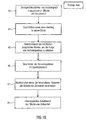
- Fig. 1c Referring to a preferred implementation of filter stage 300.
- an impulse response is provided for an audio signal speaker combination. Especially for directional sound sources you will have your own impulse response for every combination of audio signal and loudspeaker. However, for other sources as well, there are different impulse responses, at least for certain combinations of audio signal and loudspeaker.
- the number of zeros to be inserted that is, the value D A is determined, as determined by step 23 in FIG Fig. 1b has been shown.
- a step 32 a number of zeroes equal to D A are inserted in the impulse response at the beginning of the impulse response to obtain a modified impulse response. This is on Fig. 8a Referenced. Fig.
- step 33 a transformation of this modified impulse response, ie the impulse response according to Fig. 8b performed in the spectral range.
- step 34 preferably a spectrally value-wise multiplication of the determined short-term spectrum, ie the short-term spectrum, which has been read from the memory due to D b and thus determined, with the transformed modified impulse response obtained in step 33 is performed Finally, to obtain a filtered short-term spectrum.
- the out-of-step stage 100 is configured to determine the sequence of short-term spectra with the feed B from a sequence of temporal samples, such that a first sample of a first block of temporal samples converted to a short-term spectrum is spaced from a first sample of a second subsequent block of temporal samples by a number of samples equal to the feed value.
- the feed value is thus defined by the respective first sample value of the new block, this feed value, as it still is based on the Fig. 1d and 1e is present for both the overlap save method and the overlap add method.
- a time value associated with a short-term spectrum is stored as a block index indicating how many advancement values the first sample of the short-term spectrum is temporally distant from a reference value.
- the reference value is z.
- the index 0 of the short-term spectrum at 249 in Fig. 9 is a block index indicating how many advancement values the first sample of the short-term spectrum is temporally distant from a reference value.
- the memory access means is preferably configured to determine the determined short-term spectrum based on the delay value and the time value of the determined short-term spectrum such that the time value of the determined short-term spectrum equals the integer result of a division from the time duration corresponding to the delay value and the time duration. which corresponds to the feed value is or is greater by one.
- exactly the integer result used which is always smaller than the actually required delay.
- the integer result plus one could also be used, whereby these values are to a certain extent a "rounding up" of the actually required delay. In the case of a rounding up, a delay that is a bit too long is reached, but this can easily be enough for applications.
- the rest z. B. greater than or equal to 50% of the time corresponding to the feed, so can be rounded up, so be taken by one greater value.
- the remainder is less than 50%, it can be "rounded off", ie the exact result of the integer division can be taken. From a rounding can actually be spoken, if the rest not z. B. is also implemented by inserting zeros.
- the rounding implementation described above will be useful if delay is applied only with granulation of a block length, that is, if no finer delay is achieved by inserting zeroes in an impulse response. If, on the other hand, a finer delay is achieved by inserting zeroes into an impulse response, the block offset is rounded and not rounded up to determine the block offset.
- Fig. 9 shows a special memory 300 having an input interface 250 and an output interface 360.
- the audio signal 1 the audio signal 2, the audio signal 3 and the audio signal 4 is stored in the memory.
- a temporal sequence of short-term spectra with exemplary seven short-term spectra.
- the spectra are read into the memory so that there are always seven short-term spectra in the memory and then, when the memory is filled and another new short-term spectrum is introduced into the memory, the corresponding short-term spectrum "drops out" at the output 260 of the memory. This falling out is implemented by overwriting the memory cells, for example, or by resorting the indices to the individual memory fields accordingly, and is in Fig.
- the access control accesses via an access control line 265 in order to read out certain memory fields, that is to say certain short-term spectra, which are then sent via a readout output 267 to the filter stage 300 of FIG Fig. 1a to be delivered.
- a particular example access control could be used to implement Fig. 4 and there for specific OS blocks, as in Fig. 9 are shown, ie for certain audio signal speaker combinations corresponding short-term spectra of the audio signals at the corresponding time value, which is a multiple of B in Fig. 9 is at 269, read.
- the delay value could be such that a delay of two feed lengths 2B is required for the combination OS 301.
- no delay ie a delay of 0 through the delay value, could be required for the combination OS 304, while a delay of five feed values, ie 5B, is required for OS 302, as described in US Pat Fig. 9 is shown.
- the memory access controller 265 would be in accordance with the table 270 in FIG Fig. 9 and then provide the appropriate short-term spectra, via output 267, to the filter stage, as still referring to FIG Fig. 4 is set out.
- the storage depth is at the in Fig. 9
- seven short-term spectra are shown, so that a delay can be implemented that is at most equal to the time duration corresponding to six feed values B.
- the memory in Fig. 9 a value of D b of Fig. 1b , Step 21 of a maximum of 6 can be implemented.
- the memory may be larger or smaller or deeper or less deep.
- the filter stage is designed to determine a modified impulse response from an impulse response of a filter provided for the combination of loudspeaker and audio signal by inserting a number of zeros at the beginning of the impulse response, the number of zeros depends on the delay value for the combination of audio signal and loudspeaker and the selected specific short-term spectrum for the combination of audio signal and loudspeaker.
- the filter stage is adapted to insert a number of zeros such that a time duration equal to the number of zeros and equal to the value D A may be less than or equal to the remainder of the integer division from the residual value D r and Sampling time T A of Fig. 1b is. Still referring to Fig.
- the impulse response of the filter may be an impulse response for a fractional delay filter configured to achieve a delay according to a fraction of a time between adjacent discrete impulse response values, the fraction equal to the delay value (D - D b x B - D A x T A ) of Fig. 1b is, as it also from 26 in Fig. 1b is apparent.
- the memory 200 for each audio source comprises a frequency domain delay line or FDL 201, 202, 203 of FIG Fig. 4 where FDL stands for Frequency Delay Line.
- FDL stands for Frequency Delay Line.
- the FDL 201, 202, 203 which also in Fig. 9 shown schematically accordingly , allows random access to the short-term spectra stored for the corresponding source or audio signal, with access via a time value or index 269 executable for each short-term spectrum.
- the Hin transformation stage is formed with a number of transformation blocks 101, 102, 103 equal to the number of audio signals.
- the re-transformation stage 800 is formed with a number of transformation blocks 101, 102, 103 equal to the number of speakers.
- a frequency-domain delay line 201, 202, 203 is provided for each audio source for each audio signal, and further the filter stage is designed such that it contains a number of individual filters 301, 302, 303, 304, 305, 306, 307, 308, 309, wherein the number of individual filters is equal to the product of the number of audio sources and the number of speakers. In other words, this means that for each audio signal-speaker combination, a separate individual filter is included for simplicity Fig. 4 labeled OS is present.
- the down-transformation stage 100 and the back-transformation stage 800 are formed according to an overlap-save method, which will be described below with reference to FIG Fig. 1d is explained.
- the overlap save method is a fast folding method.
- the in Fig. 1e is explained, the input sequence is decomposed into overlapping subsequences, as at 36 in FIG Fig. 1d is shown. From the formed periodic folding products (cyclic folding) then those parts are taken that match the aperiodic, fast folding.
- the overlap save method can also be used to efficiently implement higher order FIR filters.
- the blocks formed in step 36 are then processed in the out-of-step stage 100 of FIG Fig.
- the output signal which results from the convolution of two finite signals, can generally be divided into three parts, the transient response, the stationary behavior and the decay behavior.
- the input signal is split into segments and each segment is individually folded by cyclic convolution with a filter.
- both the out-of-step stage 100 and the back-to-back stage 800 may be configured to perform an overlap-add method.
- the overlap-add technique also referred to as segmented convolution, is also a fast convolution method and is controlled such that an input sequence is split into actually contiguous blocks of samples at a feed B, as shown at 43 , However, these blocks become consecutive overlapping blocks due to the addition of zeros (also referred to as zero-padding) for each block, as shown at 44.
- the input signal is thus divided into sections of length B, which are then lengthened by zero-padding according to step 44 to bring the result of the convolution operation to a greater length.
- step 44 the zero-padded blocks produced by step 44 are transformed in a step 45 by the out-of-step stage 100 to obtain the sequence of short-term spectra.
- processing of the short-term spectra in the spectral range is performed in a step 46, to then perform a back transformation of the processed spectra in a step 47 to obtain blocks of time values.
- step 48 an overlapping addition of the blocks of time values takes place to obtain a correct result.
- the results of the individual convolutions are therefore added up where the individual convolution products overlap, and the result of the operation corresponds to the convolution of a theoretically infinitely long input sequence.
- an overlapping addition of the blocks of time values is performed.
- the out-transformation stage 100 and the back-transformation stage 800 are considered as individual FFT blocks, as in FIG Fig. 4 or IFFT blocks as in Fig. 4 also shown trained.
- a DFT algorithm that is to say a discrete Fourier transformation algorithm, which may also deviate from the FFT algorithm is preferred.
- other frequency domain transformation techniques such as discrete sine transform (DST) techniques, may also be used.
- DCT Discrete cosine transformation
- MDCT modified discrete cosine transformation
- the apparatus of the present invention is preferably used for a wave-field synthesis system such that there is a wave-field synthesis operator 700 that is configured to listen to any combination of speaker or audio source using a virtual position of the audio source and position of the loudspeaker to calculate the delay value, on the basis of which the memory access controller 600 and the filter stage 300 can then operate.
- Fig. 7 shows the geometry of the labels used in the general equations of wave field synthesis, ie in the wave field synthesis operator.
- the WFS operator is frequency-dependent, thus having a dedicated amplitude and phase corresponding to a frequency-dependent delay for each frequency.
- this frequency dependent operation requires filtering of the time domain signal.
- This filtering operation can be implemented as FIR filtering, where the FIR coefficients are determined by suitable design methods from the frequency-dependent WFS operator.
- the FIR filter also contains a delay, the main part of the delay (delay) being determined by the signal propagation time between the virtual source and the loudspeaker and thus being frequency-independent, ie constant.
- this frequency-dependent delay is achieved by the in conjunction with the Fig. 1a-1e described procedures edited.
- the present invention may also be applied to alternative implementations where the sources are non-directional, or where there are only frequency independent delays, or where fast convolution is generally to be employed along with a delay between certain audio signal speaker combinations.
- the sound field of the primary source is generated in the region y ⁇ y L by using a linear distribution of secondary monopole sources along x (black dots).
- the speed must be V n ⁇ r ⁇ ⁇ the primary source ⁇ be known at the positions of the secondary sources according to their normals n ,
- ⁇ is the angular frequency
- c is the speed of sound
- H 0 2 ⁇ ⁇ c ⁇ r ⁇ R - r ⁇ is the second order Hankel function of order 0.
- the path from the primary source position to the secondary source position is designated by r.
- r R is the path from the secondary source to the receiver R.
- G ( ⁇ , ⁇ ) 1.
- monopole sources In addition to the synthesis of monopole sources, a common WFS system makes it possible to render planar wavefronts, called plane waves. These may be considered monopole sources arranged at an infinite distance. As in the case of monopole sources, the resulting synthetic operator consists of a static filter, a gain factor, and a time delay.
- the gain factor A depends on the directional characteristic, the orientation and the frequency of the virtual source as well as on the positions of the virtual and secondary sources.
- time-discrete filters for the directional characteristics of the frequency response (8) must be determined. Due to their ability to approximate arbitrary frequency responses and their inherent stability, only FIR filters are considered here.
- K is the order of magnitude of the directivity filter. Since such filters are required for any combination of N virtual sources and M loudspeakers, the generation must be relatively efficient.
- a simple window (or frequency scan design) is used here.
- the desired frequency response (9) is evaluated at K + 1 equidistantly sampled frequency values in the interval 0 ⁇ ⁇ ⁇ 2 ⁇ .
- IFT inverse discrete Fourier transform
- this design method allows for several optimizations.
- the directivity filters h m, n [ k ] introduce synthesis errors in two ways. On the one hand, the limited filter order leads to an imperfect approximation of A D ( r R , r , ⁇ , ⁇ ). On the other hand, the infinite summation of (4) must be replaced by a finite limit. As a result, the beam width of the generated directivity characteristics can not become infinitely narrow.
- Fig. 2 shows the basic structure of signal processing when using a simple WFS operator based on a scale & delay operation. Shown is the signal processing structure of WFS processing systems for the synthesis of basic primary source types.
- WFS rendering is commonly implemented as a discrete-time processing system. It consists of two general tasks: computation of the synthesis operator and application of this operator to the time-discrete source signals. The latter is referred to below as WFS processing.
- the effect of the synthetic operator on overall complexity is typically low because it is relatively rarely calculated. If the source properties change only discretely, the operator is calculated as needed. For continuously changing source properties, e.g. in the case of moving sound sources, it is typically sufficient to compute these values on a coarse grid and use simple interpolation techniques in between.
- FIG. 2 shows the structure of a typical WFS rendering system with N virtual sources and M speakers.
- S & D scale-and-delay operation
- the delay value is rounded down to the nearest integer multiple of the sample period and applied to the delay line as an indexed access.
- more complex algorithms are required to interpolate the source signal at arbitrary positions between samples.
- the number of scaling and delaying operations is formed by the product of the number of virtual sources N and the number of loudspeakers M. Thus, this product typically reaches high values. Consequently, the scaling and delaying operation is the most power-critical part of most WFS systems, even if only integer delays are used.
- Fig. 3 shows the basic structure of the signal processing when using the overlap & save technique.
- the overlap save method is a fast folding method.
- the input sequence x [n] is decomposed into overlapping subsequences. From the formed periodic folding products (cyclic folding) then those parts are taken that match the aperiodic, fast folding.
- the invention proposes a signal processing scheme based on two interacting effects.
- the first effect concerns the fact that the efficiency of FIR filters can often be increased by using fast convolution techniques in the transform domain , such as overlap-save or overlap-add.
- these algorithms transform segments of the input signal into the frequency domain by fast Fourier transform (FFT) techniques, perform convolution due to frequency domain multiplication, and transform the signal back into the time domain.
- FFT fast Fourier transform
- the filter order where transform based filtering becomes more efficient than direct convolution is typically between 16 and 50.
- the forward and inverse FFT operations form the Much of the computational effort.
- Another embodiment for reducing computational effort utilizes the structure of the WFS processing scheme.
- every input signal for a large Number of delay and filter operations used is used.
- the results are summed for a large number of sound sources for each speaker.
- partitioning the signal processing algorithm which performs common operations only once for each input or output signal, promises great efficiencies.
- such partitioning of the WFS rendering algorithm provides significant performance improvements for moving sound sources from basic source types.
- FFT fast Fourier transforms
- the frequency domain representation is used several times to convolute the individual loudspeaker signal components by an overlap save operation, ie a complex multiplication.
- the loudspeaker signals are calculated in the frequency domain by accumulating the component signals of all sources.
- IFFT fast inverse Fourier transform
- Fig. 4 shows the basic structure of the signal processing in the use of a frequency domain delay line according to the invention. Shown is a block-based transform domain WFS signal processing scheme. OS stands for overlap-save and FDL stands for Frequency-Domain Delay Line.
- Fig. 4 shows a specific implementation of the embodiment of Fig. 1a which has a matrix-shaped structure, wherein the out-of-step stage 100 comprises individual FFT blocks 101, 102, 103.
- the memory 200 includes various frequency-domain delay lines 201, 202, 203, which may be accessed via the memory access controller 600 shown in FIG Fig. 4 is not shown, to determine for each filter stage 301-309 the correct short-term spectrum and the corresponding filter stage at a given time, as shown by Fig. 9 has been set out.
- the summer 400 includes schematically summed summers 401-406, and the re-transform stage 800 includes individual ones IFFT blocks 801, 802, 803 to finally receive the loudspeaker signals.
- both the blocks 101-103 and 801-803 are designed to perform the correspondingly necessary processing steps before the actual transformation or after the actual back transformation, which are required by fast folding methods, such as the overlap-save method or the overlap-add method.
- the WFS operator determines a single delay for each source-speaker combination.
- the proposed signal processing scheme allows efficient multi-channel convolution, the application of these delays requires detailed consideration.
- integer-value sample delays can be implemented by accessing a time domain delay line with little effect on overall complexity.
- a time delay can not be implemented in the same way.
- any time delay can be readily incorporated into the FIR directivity filter.
- this approach results in very large filter lengths and hence large FFT block sizes.
- this significantly increases the computational effort and the storage requirements.
- the latency to form input blocks is unacceptable for many applications due to the blocking delay required for such large FFT sizes.
- the input signal is segmented into overlapping blocks of size L and a feed (or delay block size) of B between adjacent blocks.
- the blocks are transformed into the frequency domain and are denoted by X n [ l ], where n denotes the source and l is the block index.
- These blocks are stored in a structure that allows indexed access of the form X n [li ] to the most recent frequency domain blocks.
- This data structure is conceptually identical to Frequency Domain Delay Lines used in the context of partitioned convolution.
- the delay value D is partitioned into a multiple of the block delay magnitude and a remainder D r and D r ', respectively.
- D D b ⁇ B + D r With 0 ⁇ D r ⁇ B - 1 .
- D b ⁇ N D b ⁇ N ,
- the block delay D b is applied as an indexed access in the frequency domain delay line.
- this operation corresponds to prefixing h m, n [ k ] with D r zeros.
- the resulting filter is padded with zeroes according to the requirements of the overlap save operation.
- the frequency domain filter representation H m . n d obtained by an FFT.
- the remainder of the algorithm is identical to the usual overlap-save algorithm.
- the blocks Y m [ l ] are transformed into the time domain, and the speaker drive signals y m [k] are formed by deleting a predetermined number of samples from each time domain block.
- This signal processing structure is in Fig. 4 shown schematically.
- the proposed processing scheme can be extended to arbitrary delay values by including a FD (Fractional Delay) filter, a so-called directivity filter H m . n d k .
- FD Fractional Delay
- H m . n d k Only FIR FD filters are considered here, as they can be easily integrated into the proposed algorithm.
- the residual delay D r is partitioned into an integer part D int and a fractional delay value d, as is usual in the FD filter design.
- the integer part is integrated in H m . n d k by prefixing D int zeros to h m, n [ k ].
- the fractional delay value is applied H m .
- Fig. 5 shows the basic structure of the signal processing with a frequency domain delay line according to the invention.
- the source signal x k is transformed into overlapping FFT calculation blocks 502 of the block length L into the spectra, the FFT calculation blocks having an overlap of length (LB) and a length B feed.
- the fast convolution after the overlap-save method (OS) and the backward transformation with an IFFT into the loudspeaker signals y 0 ... Y M-1 are performed at the step 503.
- the decisive factor here is the way in which access to the spectra takes place. Exemplary accesses 504, 505, 506 and 507 are shown in the figure. Based at the time of access 507, the accesses 504, 505 and 506 are in the past.
- the speaker 511 when the speaker 511 is accessed with the access 507 and the speakers 510, 512 are simultaneously driven with the access 506, it appears to the listener as if the speaker signals of the speakers 510, 512 are delayed from the speaker signal of the speaker 511 , The same applies to the access 505 and the loudspeaker signals of the loudspeakers 509, 513 as well as to the access 504 and the loudspeaker signals of the loudspeakers 508, 514.
- each individual speaker can be controlled with a delay which corresponds to a multiple of the block feed B. If a further delay is to be provided which is less than the block feed B, then this can be achieved by prefixing the respective impulse response of the filter which is the subject of the overlap-save operation.
- the main parameters that determine the complexity of a directional sound source processing algorithm are the number of virtual sources N, the number of loudspeakers M , and the filtering order of the directional filter K.
- the Displacement between adjacent input blocks also referred to as block delay B
- performance and memory requirements are also referred to as block delay B
- the blockwise operation of the fast convolution algorithms introduces an implementation latency of B-1 samples.
- the maximum allowable delay value, referred to as D max given as a number of samples, affects the amount of memory required for the delay line structures.
- linear convolution performs NM time domain convolutions of order K. This amounts to NM ( 2K + 1) commands per sample.
- M (N -1 ) real additions are needed to accumulate the speaker drive signals.
- the memory required for a single delay line is D max + K floating point values.
- Each of the MN FIR filters h m, n [ k ] requires K + 1 floating-point memory words.
- the second algorithm calculates the MN FIR filters separately using the overlap-save fast convolution method.
- a real-valued FFT of size L and an inverse FFT of the same size are performed.
- a command count of pLlog 2 (L) is assumed for a forward or inverse FFT of size L, where p is a proportionality constant that depends on the actual implementation. For p, a value between 2.5 and 3 can be assumed.
- the complex vector multiplication of length L performed in the overlap-save method requires about L / 2 complex multiplications. Since a single complex multiplication is implemented by 6 arithmetic instructions, the overhead for vector multiplication is 3L instructions.
- filtering requires the use of the overlap-save method M N K + B B ⁇ 2 ⁇ p log 2 K + B + 3 for a single output sample on all speaker signals.
- the overhead of accumulating the loudspeaker signals M ( N- 1) amounts to commands.
- the delay line memory is identical to the linear convolution algorithm.
- a single FFT or inverse FFT operation requires p (K + 2B-1) log 2 (K + 2B-1) instructions.
- N forward and M inverse FFT operations are required for each audio block.
- the complex multiplication and addition are both performed on the frequency domain representation and require 3 (K + 2B-1) and K + 2B-1 instructions, respectively, for each symmetric frequency domain block of length K + 2B-1.
- Fig. 6a As shown, the efficiency of the filter-wise fast convolution algorithm exceeds that of the linear convolution algorithm by an almost constant factor.
- the linear convolution algorithms require about 2 , 9 10 6 memory words.
- the fast filter-by-convolution algorithm uses about 5.0 ⁇ 10 6 floating point memory locations.
- the increase is due to the size of the precalculated frequency domain filter representations.
- the proposed algorithm requires about 8.6 x 10 6 words of memory due to the frequency domain delay line and the increased block size for the frequency domain representations of the input signal and the filters.
- the performance improvement of the proposed algorithm as compared to filter-wise fast convolution is gained by an increase in required memory of about 72.7%.
- the proposed algorithm may be considered as a space-time tradeoff that uses additional memory to store pre-computed results, such as frequency domain representations of the input signal, to allow for more efficient implementation.
- the additional memory requirements can have a detrimental effect on performance, such as reduced cache locality.
- the reduced number of instructions that imply a reduced number of memory accesses will minimize this effect. It is therefore necessary to examine and evaluate the performance gains of the proposed algorithm for the intended hardware architecture.
- the parameters of the algorithm such as the FFT block size L or the block delay B, must be matched to the specific target platform.
- the method according to the invention can be implemented in hardware or in software.
- the implementation may be on a non-transitory storage medium, a digital storage medium, in particular a floppy disk or CD with electronically readable control signals, which may be used with a programmable computer system that the process is performed.
- the invention thus also consists in a computer program product with a program code stored on a machine-readable carrier for carrying out the method when the computer program product runs on a computer.
- the invention can thus be realized as a computer program with a program code for carrying out the method when the computer program runs on a computer.
Landscapes
- Engineering & Computer Science (AREA)
- Signal Processing (AREA)
- Physics & Mathematics (AREA)
- Acoustics & Sound (AREA)
- Health & Medical Sciences (AREA)
- Otolaryngology (AREA)
- General Health & Medical Sciences (AREA)
- Computational Linguistics (AREA)
- Audiology, Speech & Language Pathology (AREA)
- Human Computer Interaction (AREA)
- Multimedia (AREA)
- Stereophonic System (AREA)
- Circuit For Audible Band Transducer (AREA)
Claims (19)
- Dispositif pour calculer des signaux de haut-parleur pour une pluralité de haut-parleurs à l'aide d'une pluralité de sources audio, dans lequel une source audio présente un signal audio (10), aux caractéristiques suivantes:un étage de transformation directe (100) destiné à transformer par bloc chaque signal audio (10) au domaine spectral, pour obtenir pour chaque signal audio une pluralité de spectres de courte durée successifs dans le temps;une mémoire (200) destinée à mémoriser un certain nombre de spectres de courte durée successifs dans le temps pour chaque signal audio;une commande d'accès à la mémoire (600) destinée à accéder à un spectre de courte durée déterminé parmi la pluralité de spectres de courte durée successifs dans le temps pour une combinaison d'un haut-parleur et d'un signal audio sur base d'une valeur de temporisation (701);un étage de filtre (300) destiné à filtrer le spectre de courte durée déterminé pour la combinaison du signal audio et du haut-parleur par un filtre qui est prévu pour la combinaison du signal audio et du haut-parleur, de sorte que pour chaque combinaison d'un signal audio et d'un haut-parleur soit obtenu un spectre de courte durée filtré;un étage additionneur (400) destiné à additionner les spectres de courte durée filtrés pour un haut-parleur, pour obtenir pour chaque haut-parleur des spectres de courte durée additionnés; etun étage de transformation inverse (800) destiné à transformer inversement par bloc des spectres de courte durée additionnés pour les haut-parleurs au domaine temporel, pour obtenir les signaux de haut-parleur.
- Dispositif selon la revendication 1, dans lequel l'étage de transformation directe (100) est réalisé pour déterminer la séquence de spectres de courte durée avec une valeur d'avance (B) à partir d'une séquence de valeurs de balayage dans le temps, de sorte qu'une première valeur de balayage d'un premier bloc de valeurs de balayage dans le temps qui sont transformées en un spectre de courte durée soit distante d'une première valeur de balayage d'un deuxième bloc de valeurs de balayage dans le temps suivant d'un nombre de valeurs de balayage qui est égal à la valeur d'avance,
dans lequel à un spectre de courte durée est associé un indice de bloc (269) qui indique le nombre de valeurs d'avance duquel la première valeur de balayage du spectre de courte durée est distante dans le temps d'une valeur de référence (249),
dans lequel la commande d'accès à la mémoire (600) est réalisée pour déterminer le spectre de courte durée déterminé sur base de la valeur de temporisation (701) et de l'indice de bloc (269) du spectre de courte durée déterminé, de sorte que l'indice de bloc (269) du spectre de courte durée déterminé soit égal à un résultat de nombre entier d'une division d'une durée correspondant à la valeur de temporisation et de la durée correspondant à la valeur d'avance, ou soit supérieur de 1. - Dispositif selon la revendication 1 ou 2,
dans lequel l'étage de filtre (300) est réalisé pour déterminer, à partir d'une réponse impulsionnelle d'un filtre qui est prévu pour la combinaison d'un haut-parleur et d'un signal audio, une réponse impulsionnelle modifiée par le fait qu'il est inséré un nombre de zéros au début dans le temps de la réponse impulsionnelle, le nombre de zéros étant fonction de la valeur de temporisation (701) pour la combinaison du signal audio et du haut-parleur et de l'indice de bloc du spectre de courte durée déterminé pour la combinaison du signal audio et du haut-parleur. - Dispositif selon la revendication 3, dans lequel l'étage de filtre 300 est réalisé pour insérer un nombre de zéros tel qu'une durée correspondant au nombre de zéros soit inférieure ou égale au reste d'une division de nombre entier de la durée correspondant à la valeur de temporisation par la durée correspondant à la valeur d'avance.
- Dispositif selon la revendication 4, dans lequel le filtre présente un filtre à retard fractionné qui est réalisé pour mettre en oeuvre une temporisation d'une fraction d'une durée entre deux valeurs de réponse impulsionnelle discrète adjacentes, où la fraction est fonction du résultat de nombre entier de la division de la durée correspondant à la valeur de temporisation par la durée correspondant à la vitesse d'avance, et du nombre de zéros insérés dans la réponse impulsionnelle.
- Dispositif selon l'une des revendications précédentes, dans lequel l'étage de filtre (300) est réalisé pour multiplier le spectre de courte durée, par valeur spectrale, par une fonction de transfert du filtre.
- Dispositif selon la revendication 1, dans lequel la mémoire (200) présente, pour chaque source audio, une ligne de temporisation de domaine fréquentiel (201, 202, 203) avec accès aléatoire aux spectres de courte durée mémorisés pour cette source audio, un accès pouvant être réalisé par un indice de bloc (269) pour chaque spectre de courte durée.
- Dispositif selon l'une des revendications précédentes,
dans lequel l'étage de transformation directe (100) présente un nombre de blocs de transformation (101, 102, 103) qui est égal au nombre de sources audio,
dans lequel l'étage de transformation inverse (800) présente un nombre de blocs de transformation (801, 802, 803) qui est égal au nombre de signaux de haut-parleur,
dans lequel un nombre de lignes de temporisation de domaine fréquentiel (201, 202, 203) est égal au nombre de sources audio, et
dans lequel l'étage de filtre (300) présente un nombre de filtres individuels (301, 302, 303, 304, 305, 306, 307, 308, 309) qui est égal au produit du nombre de sources audio par le nombre de signaux de haut-parleur. - Dispositif selon l'une des revendications précédentes,
dans lequel l'étage de transformation directe et l'étage de transformation inverse sont réalisés selon un procédé de recouvrement-économie,
dans lequel l'étape de transformation directe (100) est réalisé pour décomposer le signal audio à l'aide d'une valeur d'avance (B) en blocs se recouvrant, pour obtenir les spectres de courte durée, et
dans lequel l'étage de transformation inverse (800) est réalisé pour rejeter, après la transformation inverse des spectres de courte durée filtrés pour un haut-parleur, certaines zones dans les blocs transformés inversement et assembler l'un à l'autre les segments non rejetés, pour obtenir le signal de haut-parleur pour le haut-parleur. - Dispositif selon l'une des revendications 1 à 8,
dans lequel l'étage de transformation directe (100) et l'étage de transformation inverse (800) sont réalisés selon un procédé de recouvrement-addition,
dans lequel l'étage de transformation directe (100) est réalisé pour décomposer le signal audio à l'aide d'une valeur d'avance (B) en blocs adjacents l'un à l'autre qui sont remplis de zéros (zero padding) selon le procédé de recouvrement-addition, dans lequel est réalisée une transformation avec des blocs remplis de zéros selon le procédé de recouvrement-addition,
dans lequel l'étage de transformation inverse (800) est réalisé pour additionner, après la transformation inverse des spectres additionnés pour un haut-parleur, les zones se recouvrant de blocs transformés inversement, pour obtenir le signal de haut-parleur pour le haut-parleur. - Dispositif selon l'une des revendications précédentes,
dans lequel l'étage de transformation directe (100) et l'étage de transformation inverse (800) sont réalisés pour exécuter un algorithme de transformée de Fourier numérique ou un algorithme de transformée de Fourier numérique inverse. - Dispositif selon l'une des revendications précédentes, présentant par ailleurs la caractéristique suivante:un opérateur de synthèse de champ d'ondes (700) qui est réalisé pour générer, pour chaque combinaison d'un haut-parleur et d'une source audio, à l'aide d'une position virtuelle de la source audio et de la position du haut-parleur, la valeur de temporisation (700) et l'alimenter vers la commande d'accès à la mémoire (600) ou à l'étage de filtre (300).
- Dispositif selon l'une des revendications précédentes, dans lequel la source audio présente une caractéristique fonction de la direction, l'étage de filtre (200) étant réalisé pour utiliser des filtres différents pour différentes combinaisons de haut-parleurs et de signaux audio.
- Dispositif selon l'une des revendications précédentes,
dans lequel l'étage de transformation directe (100) est réalisé pour réaliser la transformation par bloc à l'aide d'une avance (B),
dans lequel la commande d'accès à la mémoire (600) est réalisée pour diviser la valeur de temporisation en un multiple de l'avance et un reste, et pour accéder à l'aide du multiple de l'avance à la mémoire (200), pour récupérer le spectre de courte durée déterminé. - Dispositif selon la revendication 14, dans lequel l'étage de filtre (300) est réalisé pour former le filtre à l'aide du reste.
- Dispositif selon l'une des revendications 1 à 13,
dans lequel l'étage de transformation directe (100) est réalisé pour utiliser une transformée de Fourier rapide par bloc dont la longueur est égale à K + B, où B est une avance lors de la génération de blocs successifs, où K est un ordre du filtre de l'étage de filtre lorsque le filtre est réalisé pour ne pas fournir d'autre contribution à la temporisation. - Dispositif selon l'une des revendications 1 à 15,
dans lequel l'étage de transformation directe (100) est réalisé pour utiliser une transformée de Fourier rapide par bloc dont la longueur est égale à K + 2 B - 1, où B est une avance lors de la génération de blocs successifs, et dans lequel K un ordre du filtre sans ligne de temporisation, dans une réponse impulsionnelle ayant été insérés tout au plus (B-1) zéros pour que soit fourni par le filtre une temporisation additionnelle. - Procédé pour calculer des signaux de haut-parleur pour une pluralité de haut-parleurs à l'aide d'une pluralité de sources audio, dans lequel une source audio présente un signal audio (10), aux étapes suivantes consistant à:transformer directement par bloc chaque signal audio (10) au domaine spectral, pour obtenir pour chaque signal audio une pluralité de spectres de courte durée successifs dans le temps;mémoriser un certain nombre de spectres de courte durée successifs dans le temps pour chaque signal audio;accéder à un spectre de courte durée déterminé parmi la pluralité de spectres de courte durée successifs dans le temps pour une combinaison d'un haut-parleur et d'un signal audio sur base d'une valeur de temporisation (701);filtrer le spectre de courte durée déterminé pour la combinaison du signal audio et du haut-parleur par un filtre qui est prévu pour la combinaison du signal audio et du haut-parleur, de sorte que pour chaque combinaison d'un signal audio et d'un haut-parleur soit obtenu un spectre de courte durée filtré;additionner les spectres de courte durée filtrés pour un haut-parleur, pour obtenir pour chaque haut-parleur des spectres de courte durée additionnés; ettransformer inversement par bloc des spectres de courte durée additionnés pour les haut-parleurs au domaine temporel, pour obtenir les signaux de haut-parleur.
- Programme d'ordinateur avec un code de programme pour réaliser le procédé selon la revendication 18 lorsque le code de programme est exécuté sur un ordinateur ou un processeur.
Applications Claiming Priority (2)
| Application Number | Priority Date | Filing Date | Title |
|---|---|---|---|
| DE102012200512A DE102012200512B4 (de) | 2012-01-13 | 2012-01-13 | Vorrichtung und Verfahren zum Berechnen von Lautsprechersignalen für eine Mehrzahl von Lautsprechern unter Verwendung einer Verzögerung im Frequenzbereich |
| PCT/EP2012/077075 WO2013104529A1 (fr) | 2012-01-13 | 2012-12-28 | Dispositif et procédé pour le calcul de signaux de haut-parleurs pour une pluralité de haut-parleurs, utilisant une temporisation dans la gamme de fréquence |
Publications (2)
| Publication Number | Publication Date |
|---|---|
| EP2656633A1 EP2656633A1 (fr) | 2013-10-30 |
| EP2656633B1 true EP2656633B1 (fr) | 2015-07-08 |
Family
ID=47598778
Family Applications (1)
| Application Number | Title | Priority Date | Filing Date |
|---|---|---|---|
| EP12816679.0A Active EP2656633B1 (fr) | 2012-01-13 | 2012-12-28 | Dispositif et procédé pour le calcul de signaux de haut-parleurs pour une pluralité de haut-parleurs, utilisant une temporisation dans la gamme de fréquence |
Country Status (5)
| Country | Link |
|---|---|
| US (2) | US9666203B2 (fr) |
| EP (1) | EP2656633B1 (fr) |
| JP (2) | JP5969627B2 (fr) |
| DE (1) | DE102012200512B4 (fr) |
| WO (1) | WO2013104529A1 (fr) |
Families Citing this family (10)
| Publication number | Priority date | Publication date | Assignee | Title |
|---|---|---|---|---|
| DE102012200512B4 (de) | 2012-01-13 | 2013-11-14 | Fraunhofer-Gesellschaft zur Förderung der angewandten Forschung e.V. | Vorrichtung und Verfahren zum Berechnen von Lautsprechersignalen für eine Mehrzahl von Lautsprechern unter Verwendung einer Verzögerung im Frequenzbereich |
| US10166388B2 (en) * | 2013-10-07 | 2019-01-01 | Med-El Elektromedizinische Geraete Gmbh | Method for extracting temporal features from spike-like signals |
| KR102413692B1 (ko) * | 2015-07-24 | 2022-06-27 | 삼성전자주식회사 | 음성 인식을 위한 음향 점수 계산 장치 및 방법, 음성 인식 장치 및 방법, 전자 장치 |
| KR102192678B1 (ko) | 2015-10-16 | 2020-12-17 | 삼성전자주식회사 | 음향 모델 입력 데이터의 정규화 장치 및 방법과, 음성 인식 장치 |
| US9497561B1 (en) * | 2016-05-27 | 2016-11-15 | Mass Fidelity Inc. | Wave field synthesis by synthesizing spatial transfer function over listening region |
| WO2018071546A1 (fr) * | 2016-10-11 | 2018-04-19 | The Research Foundation For The State University Of New York | Système, procédé et accélérateur de traitement des couches de réseau neuronal convolutif |
| CN110603821B (zh) | 2017-05-04 | 2025-06-24 | 杜比国际公司 | 渲染具有表观大小的音频对象 |
| US11158341B2 (en) * | 2017-12-22 | 2021-10-26 | Soundtheory Limited | Frequency response method and apparatus |
| US11122363B2 (en) * | 2018-03-01 | 2021-09-14 | Nippon Telegraph And Telephone Corporation | Acoustic signal processing device, acoustic signal processing method, and acoustic signal processing program |
| US11356790B2 (en) * | 2018-04-26 | 2022-06-07 | Nippon Telegraph And Telephone Corporation | Sound image reproduction device, sound image reproduction method, and sound image reproduction program |
Family Cites Families (12)
| Publication number | Priority date | Publication date | Assignee | Title |
|---|---|---|---|---|
| WO1999001953A1 (fr) | 1997-07-02 | 1999-01-14 | Creative Technology, Ltd. | Boite a sons a decouplage d'execution des instructions et sequencement des donnees audio |
| JP4627880B2 (ja) | 1997-09-16 | 2011-02-09 | ドルビー ラボラトリーズ ライセンシング コーポレイション | リスナーの周囲にある音源の空間的ひろがり感を増強するためのステレオヘッドホンデバイス内でのフィルタ効果の利用 |
| WO1999049574A1 (fr) * | 1998-03-25 | 1999-09-30 | Lake Technology Limited | Procede et appareil de traitement de signaux audio |
| DE102005008369A1 (de) | 2005-02-23 | 2006-09-07 | Fraunhofer-Gesellschaft zur Förderung der angewandten Forschung e.V. | Vorrichtung und Verfahren zum Simulieren eines Wellenfeldsynthese-Systems |
| DE102005008366A1 (de) | 2005-02-23 | 2006-08-24 | Fraunhofer-Gesellschaft zur Förderung der angewandten Forschung e.V. | Vorrichtung und Verfahren zum Ansteuern einer Wellenfeldsynthese-Renderer-Einrichtung mit Audioobjekten |
| DE102006010212A1 (de) | 2006-03-06 | 2007-09-20 | Fraunhofer-Gesellschaft zur Förderung der angewandten Forschung e.V. | Vorrichtung und Verfahren zur Simulation von WFS-Systemen und Kompensation von klangbeeinflussenden WFS-Eigenschaften |
| US9197977B2 (en) * | 2007-03-01 | 2015-11-24 | Genaudio, Inc. | Audio spatialization and environment simulation |
| US8520873B2 (en) | 2008-10-20 | 2013-08-27 | Jerry Mahabub | Audio spatialization and environment simulation |
| DE102007059597A1 (de) | 2007-09-19 | 2009-04-02 | Fraunhofer-Gesellschaft zur Förderung der angewandten Forschung e.V. | Eine Vorrichtung und ein Verfahren zur Ermittlung eines Komponentensignals in hoher Genauigkeit |
| CN101884065B (zh) * | 2007-10-03 | 2013-07-10 | 创新科技有限公司 | 用于双耳再现和格式转换的空间音频分析和合成的方法 |
| EP2450880A1 (fr) * | 2010-11-05 | 2012-05-09 | Thomson Licensing | Structure de données pour données audio d'ambiophonie d'ordre supérieur |
| DE102012200512B4 (de) | 2012-01-13 | 2013-11-14 | Fraunhofer-Gesellschaft zur Förderung der angewandten Forschung e.V. | Vorrichtung und Verfahren zum Berechnen von Lautsprechersignalen für eine Mehrzahl von Lautsprechern unter Verwendung einer Verzögerung im Frequenzbereich |
-
2012
- 2012-01-13 DE DE102012200512A patent/DE102012200512B4/de not_active Expired - Fee Related
- 2012-12-28 JP JP2014551566A patent/JP5969627B2/ja not_active Expired - Fee Related
- 2012-12-28 WO PCT/EP2012/077075 patent/WO2013104529A1/fr not_active Ceased
- 2012-12-28 EP EP12816679.0A patent/EP2656633B1/fr active Active
-
2014
- 2014-07-11 US US14/329,457 patent/US9666203B2/en active Active
-
2015
- 2015-12-22 JP JP2015249310A patent/JP6254142B2/ja active Active
-
2017
- 2017-05-24 US US15/603,946 patent/US10347268B2/en active Active
Also Published As
| Publication number | Publication date |
|---|---|
| US10347268B2 (en) | 2019-07-09 |
| WO2013104529A1 (fr) | 2013-07-18 |
| US20180012612A1 (en) | 2018-01-11 |
| US20140348337A1 (en) | 2014-11-27 |
| DE102012200512A1 (de) | 2013-07-18 |
| US9666203B2 (en) | 2017-05-30 |
| JP6254142B2 (ja) | 2017-12-27 |
| EP2656633A1 (fr) | 2013-10-30 |
| JP2015507421A (ja) | 2015-03-05 |
| JP2016106459A (ja) | 2016-06-16 |
| US20180358029A9 (en) | 2018-12-13 |
| JP5969627B2 (ja) | 2016-08-17 |
| DE102012200512B4 (de) | 2013-11-14 |
Similar Documents
| Publication | Publication Date | Title |
|---|---|---|
| EP2656633B1 (fr) | Dispositif et procédé pour le calcul de signaux de haut-parleurs pour une pluralité de haut-parleurs, utilisant une temporisation dans la gamme de fréquence | |
| EP3117631B1 (fr) | Dispositif et procédé pour traiter un signal dans le domaine fréquentiel | |
| DE102006050068B4 (de) | Vorrichtung und Verfahren zum Erzeugen eines Umgebungssignals aus einem Audiosignal, Vorrichtung und Verfahren zum Ableiten eines Mehrkanal-Audiosignals aus einem Audiosignal und Computerprogramm | |
| EP2080411B1 (fr) | Dispositif et procédé pour produire un certain nombre de signaux de haut-parleur pour un réseau de haut-parleurs définissant un espace de restitution | |
| EP1854334B1 (fr) | Dispositif et procede de production d'un signal stereo code d'un morceau audio ou d'un flux de donnees audio | |
| EP1671516B1 (fr) | Procede et dispositif de production d'un canal a frequences basses | |
| EP3183891B1 (fr) | Calcule de coefficients d'un filtre rif pour un filtre d'un dispositif de beamforming | |
| EP2189010A1 (fr) | Système et procédé pour déterminer un signal de composante avec une grande précision | |
| EP2891334B1 (fr) | Génération de son multivoies à partir de signaux audio stéréo | |
| EP1972181B1 (fr) | Dispositif et procédé de simulation de systèmes wfs et de compensation de propriétés wfs influençant le son | |
| EP2754151B1 (fr) | Dispositif, procédé et système électroacoustique de prolongement d'un temps de réverbération | |
| EP2485504B1 (fr) | Production de zones silencieuses à l'intérieur de la zone d'auditeurs d'un système de retransmission à plusieurs canaux | |
| EP3275212B1 (fr) | Procédé d'analyse et de décomposition de signaux audio stéréophoniques | |
| EP2571290B1 (fr) | Synthèse de champ sonore locale par l'intermédiaire d'un corps diffusant virtuel | |
| EP2487891B1 (fr) | Suppression de l'écho acoustique dans des systèmes Full-Duplex |
Legal Events
| Date | Code | Title | Description |
|---|---|---|---|
| PUAI | Public reference made under article 153(3) epc to a published international application that has entered the european phase |
Free format text: ORIGINAL CODE: 0009012 |
|
| 17P | Request for examination filed |
Effective date: 20130723 |
|
| AK | Designated contracting states |
Kind code of ref document: A1 Designated state(s): AL AT BE BG CH CY CZ DE DK EE ES FI FR GB GR HR HU IE IS IT LI LT LU LV MC MK MT NL NO PL PT RO RS SE SI SK SM TR |
|
| GRAP | Despatch of communication of intention to grant a patent |
Free format text: ORIGINAL CODE: EPIDOSNIGR1 |
|
| RIC1 | Information provided on ipc code assigned before grant |
Ipc: H04R 3/12 20060101AFI20150121BHEP Ipc: G10L 19/26 20130101ALI20150121BHEP Ipc: H04R 29/00 20060101ALI20150121BHEP |
|
| DAX | Request for extension of the european patent (deleted) | ||
| INTG | Intention to grant announced |
Effective date: 20150216 |
|
| GRAS | Grant fee paid |
Free format text: ORIGINAL CODE: EPIDOSNIGR3 |
|
| GRAA | (expected) grant |
Free format text: ORIGINAL CODE: 0009210 |
|
| AK | Designated contracting states |
Kind code of ref document: B1 Designated state(s): AL AT BE BG CH CY CZ DE DK EE ES FI FR GB GR HR HU IE IS IT LI LT LU LV MC MK MT NL NO PL PT RO RS SE SI SK SM TR |
|
| REG | Reference to a national code |
Ref country code: GB Ref legal event code: FG4D Free format text: NOT ENGLISH |
|
| REG | Reference to a national code |
Ref country code: AT Ref legal event code: REF Ref document number: 736179 Country of ref document: AT Kind code of ref document: T Effective date: 20150715 Ref country code: CH Ref legal event code: EP |
|
| REG | Reference to a national code |
Ref country code: IE Ref legal event code: FG4D Free format text: LANGUAGE OF EP DOCUMENT: GERMAN |
|
| REG | Reference to a national code |
Ref country code: DE Ref legal event code: R096 Ref document number: 502012003769 Country of ref document: DE |
|
| REG | Reference to a national code |
Ref country code: NL Ref legal event code: MP Effective date: 20150708 |
|
| REG | Reference to a national code |
Ref country code: FR Ref legal event code: PLFP Year of fee payment: 4 |
|
| REG | Reference to a national code |
Ref country code: LT Ref legal event code: MG4D |
|
| PG25 | Lapsed in a contracting state [announced via postgrant information from national office to epo] |
Ref country code: LV Free format text: LAPSE BECAUSE OF FAILURE TO SUBMIT A TRANSLATION OF THE DESCRIPTION OR TO PAY THE FEE WITHIN THE PRESCRIBED TIME-LIMIT Effective date: 20150708 Ref country code: LT Free format text: LAPSE BECAUSE OF FAILURE TO SUBMIT A TRANSLATION OF THE DESCRIPTION OR TO PAY THE FEE WITHIN THE PRESCRIBED TIME-LIMIT Effective date: 20150708 Ref country code: GR Free format text: LAPSE BECAUSE OF FAILURE TO SUBMIT A TRANSLATION OF THE DESCRIPTION OR TO PAY THE FEE WITHIN THE PRESCRIBED TIME-LIMIT Effective date: 20151009 Ref country code: NO Free format text: LAPSE BECAUSE OF FAILURE TO SUBMIT A TRANSLATION OF THE DESCRIPTION OR TO PAY THE FEE WITHIN THE PRESCRIBED TIME-LIMIT Effective date: 20151008 Ref country code: FI Free format text: LAPSE BECAUSE OF FAILURE TO SUBMIT A TRANSLATION OF THE DESCRIPTION OR TO PAY THE FEE WITHIN THE PRESCRIBED TIME-LIMIT Effective date: 20150708 |
|
| PG25 | Lapsed in a contracting state [announced via postgrant information from national office to epo] |
Ref country code: IS Free format text: LAPSE BECAUSE OF FAILURE TO SUBMIT A TRANSLATION OF THE DESCRIPTION OR TO PAY THE FEE WITHIN THE PRESCRIBED TIME-LIMIT Effective date: 20151108 Ref country code: ES Free format text: LAPSE BECAUSE OF FAILURE TO SUBMIT A TRANSLATION OF THE DESCRIPTION OR TO PAY THE FEE WITHIN THE PRESCRIBED TIME-LIMIT Effective date: 20150708 Ref country code: RS Free format text: LAPSE BECAUSE OF FAILURE TO SUBMIT A TRANSLATION OF THE DESCRIPTION OR TO PAY THE FEE WITHIN THE PRESCRIBED TIME-LIMIT Effective date: 20150708 Ref country code: HR Free format text: LAPSE BECAUSE OF FAILURE TO SUBMIT A TRANSLATION OF THE DESCRIPTION OR TO PAY THE FEE WITHIN THE PRESCRIBED TIME-LIMIT Effective date: 20150708 Ref country code: SE Free format text: LAPSE BECAUSE OF FAILURE TO SUBMIT A TRANSLATION OF THE DESCRIPTION OR TO PAY THE FEE WITHIN THE PRESCRIBED TIME-LIMIT Effective date: 20150708 Ref country code: PT Free format text: LAPSE BECAUSE OF FAILURE TO SUBMIT A TRANSLATION OF THE DESCRIPTION OR TO PAY THE FEE WITHIN THE PRESCRIBED TIME-LIMIT Effective date: 20151109 Ref country code: PL Free format text: LAPSE BECAUSE OF FAILURE TO SUBMIT A TRANSLATION OF THE DESCRIPTION OR TO PAY THE FEE WITHIN THE PRESCRIBED TIME-LIMIT Effective date: 20150708 |
|
| REG | Reference to a national code |
Ref country code: DE Ref legal event code: R097 Ref document number: 502012003769 Country of ref document: DE |
|
| PG25 | Lapsed in a contracting state [announced via postgrant information from national office to epo] |
Ref country code: SK Free format text: LAPSE BECAUSE OF FAILURE TO SUBMIT A TRANSLATION OF THE DESCRIPTION OR TO PAY THE FEE WITHIN THE PRESCRIBED TIME-LIMIT Effective date: 20150708 Ref country code: IT Free format text: LAPSE BECAUSE OF FAILURE TO SUBMIT A TRANSLATION OF THE DESCRIPTION OR TO PAY THE FEE WITHIN THE PRESCRIBED TIME-LIMIT Effective date: 20150708 Ref country code: CZ Free format text: LAPSE BECAUSE OF FAILURE TO SUBMIT A TRANSLATION OF THE DESCRIPTION OR TO PAY THE FEE WITHIN THE PRESCRIBED TIME-LIMIT Effective date: 20150708 Ref country code: EE Free format text: LAPSE BECAUSE OF FAILURE TO SUBMIT A TRANSLATION OF THE DESCRIPTION OR TO PAY THE FEE WITHIN THE PRESCRIBED TIME-LIMIT Effective date: 20150708 Ref country code: DK Free format text: LAPSE BECAUSE OF FAILURE TO SUBMIT A TRANSLATION OF THE DESCRIPTION OR TO PAY THE FEE WITHIN THE PRESCRIBED TIME-LIMIT Effective date: 20150708 |
|
| PLBE | No opposition filed within time limit |
Free format text: ORIGINAL CODE: 0009261 |
|
| STAA | Information on the status of an ep patent application or granted ep patent |
Free format text: STATUS: NO OPPOSITION FILED WITHIN TIME LIMIT |
|
| PG25 | Lapsed in a contracting state [announced via postgrant information from national office to epo] |
Ref country code: BE Free format text: LAPSE BECAUSE OF NON-PAYMENT OF DUE FEES Effective date: 20151231 Ref country code: RO Free format text: LAPSE BECAUSE OF FAILURE TO SUBMIT A TRANSLATION OF THE DESCRIPTION OR TO PAY THE FEE WITHIN THE PRESCRIBED TIME-LIMIT Effective date: 20150708 |
|
| 26N | No opposition filed |
Effective date: 20160411 |
|
| PG25 | Lapsed in a contracting state [announced via postgrant information from national office to epo] |
Ref country code: MC Free format text: LAPSE BECAUSE OF FAILURE TO SUBMIT A TRANSLATION OF THE DESCRIPTION OR TO PAY THE FEE WITHIN THE PRESCRIBED TIME-LIMIT Effective date: 20150708 Ref country code: LU Free format text: LAPSE BECAUSE OF FAILURE TO SUBMIT A TRANSLATION OF THE DESCRIPTION OR TO PAY THE FEE WITHIN THE PRESCRIBED TIME-LIMIT Effective date: 20151228 |
|
| REG | Reference to a national code |
Ref country code: CH Ref legal event code: PL |
|
| PG25 | Lapsed in a contracting state [announced via postgrant information from national office to epo] |
Ref country code: SI Free format text: LAPSE BECAUSE OF FAILURE TO SUBMIT A TRANSLATION OF THE DESCRIPTION OR TO PAY THE FEE WITHIN THE PRESCRIBED TIME-LIMIT Effective date: 20150708 |
|
| REG | Reference to a national code |
Ref country code: IE Ref legal event code: MM4A |
|
| PG25 | Lapsed in a contracting state [announced via postgrant information from national office to epo] |
Ref country code: CH Free format text: LAPSE BECAUSE OF NON-PAYMENT OF DUE FEES Effective date: 20151231 Ref country code: IE Free format text: LAPSE BECAUSE OF NON-PAYMENT OF DUE FEES Effective date: 20151228 Ref country code: LI Free format text: LAPSE BECAUSE OF NON-PAYMENT OF DUE FEES Effective date: 20151231 |
|
| REG | Reference to a national code |
Ref country code: FR Ref legal event code: PLFP Year of fee payment: 5 |
|
| PG25 | Lapsed in a contracting state [announced via postgrant information from national office to epo] |
Ref country code: BG Free format text: LAPSE BECAUSE OF FAILURE TO SUBMIT A TRANSLATION OF THE DESCRIPTION OR TO PAY THE FEE WITHIN THE PRESCRIBED TIME-LIMIT Effective date: 20150708 Ref country code: HU Free format text: LAPSE BECAUSE OF FAILURE TO SUBMIT A TRANSLATION OF THE DESCRIPTION OR TO PAY THE FEE WITHIN THE PRESCRIBED TIME-LIMIT; INVALID AB INITIO Effective date: 20121228 Ref country code: SM Free format text: LAPSE BECAUSE OF FAILURE TO SUBMIT A TRANSLATION OF THE DESCRIPTION OR TO PAY THE FEE WITHIN THE PRESCRIBED TIME-LIMIT Effective date: 20150708 |
|
| PG25 | Lapsed in a contracting state [announced via postgrant information from national office to epo] |
Ref country code: NL Free format text: LAPSE BECAUSE OF FAILURE TO SUBMIT A TRANSLATION OF THE DESCRIPTION OR TO PAY THE FEE WITHIN THE PRESCRIBED TIME-LIMIT Effective date: 20150708 Ref country code: CY Free format text: LAPSE BECAUSE OF FAILURE TO SUBMIT A TRANSLATION OF THE DESCRIPTION OR TO PAY THE FEE WITHIN THE PRESCRIBED TIME-LIMIT Effective date: 20150708 |
|
| PG25 | Lapsed in a contracting state [announced via postgrant information from national office to epo] |
Ref country code: MT Free format text: LAPSE BECAUSE OF FAILURE TO SUBMIT A TRANSLATION OF THE DESCRIPTION OR TO PAY THE FEE WITHIN THE PRESCRIBED TIME-LIMIT Effective date: 20150708 |
|
| REG | Reference to a national code |
Ref country code: FR Ref legal event code: PLFP Year of fee payment: 6 |
|
| PG25 | Lapsed in a contracting state [announced via postgrant information from national office to epo] |
Ref country code: MK Free format text: LAPSE BECAUSE OF FAILURE TO SUBMIT A TRANSLATION OF THE DESCRIPTION OR TO PAY THE FEE WITHIN THE PRESCRIBED TIME-LIMIT Effective date: 20150708 |
|
| PG25 | Lapsed in a contracting state [announced via postgrant information from national office to epo] |
Ref country code: AL Free format text: LAPSE BECAUSE OF FAILURE TO SUBMIT A TRANSLATION OF THE DESCRIPTION OR TO PAY THE FEE WITHIN THE PRESCRIBED TIME-LIMIT Effective date: 20150708 Ref country code: TR Free format text: LAPSE BECAUSE OF FAILURE TO SUBMIT A TRANSLATION OF THE DESCRIPTION OR TO PAY THE FEE WITHIN THE PRESCRIBED TIME-LIMIT Effective date: 20150708 |
|
| REG | Reference to a national code |
Ref country code: AT Ref legal event code: MM01 Ref document number: 736179 Country of ref document: AT Kind code of ref document: T Effective date: 20171228 |
|
| PG25 | Lapsed in a contracting state [announced via postgrant information from national office to epo] |
Ref country code: AT Free format text: LAPSE BECAUSE OF NON-PAYMENT OF DUE FEES Effective date: 20171228 |
|
| P01 | Opt-out of the competence of the unified patent court (upc) registered |
Effective date: 20230515 |
|
| PGFP | Annual fee paid to national office [announced via postgrant information from national office to epo] |
Ref country code: GB Payment date: 20251218 Year of fee payment: 14 |
|
| PGFP | Annual fee paid to national office [announced via postgrant information from national office to epo] |
Ref country code: FR Payment date: 20251218 Year of fee payment: 14 |
|
| PGFP | Annual fee paid to national office [announced via postgrant information from national office to epo] |
Ref country code: DE Payment date: 20251222 Year of fee payment: 14 |