EP2656748A1 - Appareil pour la production de brosses ou balais - Google Patents
Appareil pour la production de brosses ou balais Download PDFInfo
- Publication number
- EP2656748A1 EP2656748A1 EP12165630.0A EP12165630A EP2656748A1 EP 2656748 A1 EP2656748 A1 EP 2656748A1 EP 12165630 A EP12165630 A EP 12165630A EP 2656748 A1 EP2656748 A1 EP 2656748A1
- Authority
- EP
- European Patent Office
- Prior art keywords
- axis
- arm
- gear motor
- supporting element
- brush
- Prior art date
- Legal status (The legal status is an assumption and is not a legal conclusion. Google has not performed a legal analysis and makes no representation as to the accuracy of the status listed.)
- Withdrawn
Links
- 244000007853 Sarothamnus scoparius Species 0.000 title claims abstract description 32
- 230000000284 resting effect Effects 0.000 claims description 5
- 238000005553 drilling Methods 0.000 description 6
- 239000000463 material Substances 0.000 description 3
- 239000003082 abrasive agent Substances 0.000 description 1
- 238000011109 contamination Methods 0.000 description 1
- 238000012986 modification Methods 0.000 description 1
- 230000004048 modification Effects 0.000 description 1
Images






Classifications
-
- A—HUMAN NECESSITIES
- A46—BRUSHWARE
- A46D—MANUFACTURE OF BRUSHES
- A46D3/00—Preparing, i.e. Manufacturing brush bodies
- A46D3/08—Parts of brush-making machines
- A46D3/087—Holders or supports for brush bodies
Definitions
- the present invention relates to an apparatus for production of brushes or brooms.
- a first type of apparatus comprises a supporting element consisting of a substantially horizontal shelf, on which a plurality of bristle holding bodies of brushes or brooms is supported, a plurality of drilling tools for making in a surface of said bristle holding bodies holes that are suitable for receiving groups of bristles, and a plurality of punches that are movable in a substantially vertical direction, i.e. perpendicular to said shelf, intended for inserting groups of bristles into the holes made on said surface of said bristle holding bodies.
- Each punch moves between a first top dead centre position, in which the punch receives a group of bristles to be inserted into one of said holes of a bristle holding body and a bottom dead centre position, in which the punch inserts the group of bristles into a hole of said bristle holding body.
- the shelf supporting the bristle holding bodies is movable along two axes X and Y that are parallel to the surface of the shelf to take the bristle holding bodies from an inserting position on the shelf to a drilling position, at the drilling tools, then to a bristle inserting position, at the inserting punches of the bristle groups, and, finally to an unloading position at the end of the inserting operation of the groups of bristles.
- the motion along the axes X and Y of said shelf is also used for varying the position of each bristle holding body with respect to the drilling tools, during drilling operations, to enable said tools to make rows of holes, that are substantially spaced evenly apart, on the bristle holding body and to vary the position of said bristle holding bodies with respect to the inserting punches of the groups of bristles, to position in succession the holes made in the bristle holding body under the movement axis of the respective punch, during the inserting operation of groups of bristles into said holes.
- the shelf supporting the bristle holding bodies is further movable parallel to an axis Z that is perpendicular to the plane defined by the axes X and Y and is rotatable around an axis U that is parallel to the plane defined by the axes X and Y.
- the motion in a direction that is parallel to the axis Z and around the axis U is used to position the bristle holding bodies with respect to the drilling tools and to the punches, respectively for making the holes and for inserting the groups of bristles, for example when the surface of the bristle holding body is curved, or for making holes that are tilted with respect to the plane of the bristle holding body and inserting groups of bristles in said tilted holes.
- the movement along the axis Z is also used to take the shelf supporting the bristle holding bodies to a rest position, when the apparatus is switched off and to reposition the shelf when the apparatus is started up.
- This type of apparatus requires complex and expensive devices for moving the shelf supporting the bristle holding bodies.
- One object of the present invention is to provide an apparatus for production of brushes or brooms that is provided with simpler and less costly devices for moving the shelf supporting the bristle holding bodies.
- an apparatus for production of brushes or brooms that has a much smaller number of parts than apparatuses known from the prior art and enables, with small modifications, bodies of different types of brushes or brooms to be processed, for example bodies of rectangular, circular and cylindrical brushes or brooms.
- the movable parts of the apparatus are protected against contamination by the material used for the bristles of the brushes or brooms, inasmuch as said material cannot be introduced into and damage the moving parts. This is particularly advantageous in the production of brushes or brooms with bristles made of abrasive material.
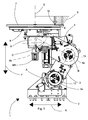
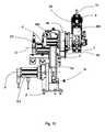
- the apparatus 1 comprises a base 2 to which a first gear motor M1 is fixed to the outlet shaft of which there is fixed, by screws 12, a first end 3a of a first arm 3.
- the first gear motor M1 rotates the first arm 3 around a first rotation axis A coinciding with the axis of the outlet shaft of the first gear motor M1.
- a second gear motor M2 is supported on a second end 3b of the first arm 3, a first end 4a of a second arm 4 being fixed to the outlet shaft of the second gear motor M2 by further screws 13.
- the second gear motor M2 rotates the second arm 4 around a second rotation axis B, coinciding with the axis of the outlet shaft of the second gear motor M2.
- a third gear motor M3 is supported on a second end 4b of the second arm 4, a supporting element 5 being fixed to the outlet shaft of the third gear motor M3, the supporting element 5 being rotated around a third axis C coinciding with the axis of the outlet shaft of the third gear motor M3.
- the first rotation axis A, the second rotation axis B and the third rotation axis C are substantially parallel to one another.
- the supporting element 5 rotatingly supports a shelf 6 intended for supporting a bristle holding body 7 having a circular shape.
- a bristle holding body 7 On the bristle holding body 7 holes 8 are made that are intended for receiving clumps of bristles 9 that are inserted into said holes 8 by a punch 10 of known type, indicated only schematically.
- the shelf 6 is rotated around a fourth rotation axis D by a fourth gear motor M4 supported on the supporting element 5.
- the first and the second arm 3 and 4 and the gear motors M1, M2 are used to move the shelf 6 in two directions X and Y that are perpendicular to one another, combining together the rotations of the first arm and of the second arm 4 around the axes A and B, respectively. Further, by means of the third gear motor M3 it is possible to rotate the shelf 6 around the third rotation axis C substantially perpendicular to the plane defined by the directions X and Y.
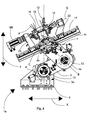
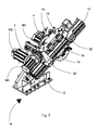
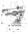
- FIGs 4 to 7 there is illustrated a second embodiment of an apparatus 1a according to the invention.
- the parts of the apparatus 1a that are the same as those of the apparatus 1 illustrated in Figures 1 to 3 are indicated by the same reference numbers used in said Figures.
- the apparatus 1a differs from the apparatus 1 illustrated in Figures 1 to 3 through the fact that a supporting element 17 is fixed to the outlet shaft of the third gear motor M3, for example a supporting element 17 in the shape of a plate, that supports a first carriage 22 and a second carriage 23 that are both movable on ball bearing guides 14.
- the first carriage 22 and the second carriage 23 rotatingly support a resting element 18 on which, by a pair of clamps 15 and 16, the body 19 of a brush or broom can be fixed that has, for example, a substantially rectangular shape, into which groups of bristles 9 have to be inserted by the punch 10.
- the resting element 18 can be rotated around a fifth axis E by a fifth gear motor M5.
- FIGs 4 and 5 two operating positions of the apparatus 1a are illustrated in which the groups of bristles 9 are inserted into the body 19 of a brush or broom with different tilts, the tilt of the groups of bristles 9 being greater in the operating position of Figure 4 .
- the apparatus 1b differs from the apparatus 1a, by the fact that the carriages 22 and 23 rotatingly support a body of a brush 20 of cylindrical shape, that is rotatable around the fifth rotation axis E by means of the fifth gear motor M5.
- the body of a brush or broom 20 is supported on the carriages 22 and 23 such that the longitudinal axis thereof coincides substantially with the fifth rotation axis E.
- the apparatus 1b is identical to the apparatus 1a.
Landscapes
- Engineering & Computer Science (AREA)
- Manufacturing & Machinery (AREA)
- Brushes (AREA)
Priority Applications (1)
| Application Number | Priority Date | Filing Date | Title |
|---|---|---|---|
| EP12165630.0A EP2656748A1 (fr) | 2012-04-26 | 2012-04-26 | Appareil pour la production de brosses ou balais |
Applications Claiming Priority (1)
| Application Number | Priority Date | Filing Date | Title |
|---|---|---|---|
| EP12165630.0A EP2656748A1 (fr) | 2012-04-26 | 2012-04-26 | Appareil pour la production de brosses ou balais |
Publications (1)
| Publication Number | Publication Date |
|---|---|
| EP2656748A1 true EP2656748A1 (fr) | 2013-10-30 |
Family
ID=46261904
Family Applications (1)
| Application Number | Title | Priority Date | Filing Date |
|---|---|---|---|
| EP12165630.0A Withdrawn EP2656748A1 (fr) | 2012-04-26 | 2012-04-26 | Appareil pour la production de brosses ou balais |
Country Status (1)
| Country | Link |
|---|---|
| EP (1) | EP2656748A1 (fr) |
Citations (5)
| Publication number | Priority date | Publication date | Assignee | Title |
|---|---|---|---|---|
| DE2826357A1 (de) * | 1978-06-16 | 1980-01-03 | Zahoransky Anton Fa | Buerstenherstellungsmaschine sowie verfahren zum herstellen von buersten |
| US5222198A (en) * | 1988-05-06 | 1993-06-22 | Kabushiki Kaisha Yaskawa Denki Seisakusho | Control method and apparatus for a robot having multi-rotating axes |
| DE10209119A1 (de) * | 2002-03-01 | 2003-09-11 | Zahoransky Anton Gmbh & Co | Bürstenherstellungsmaschine |
| DE10245899A1 (de) * | 2002-09-30 | 2004-04-08 | Dat Automatisierungstechnik Gmbh | Anschlussadapter für einen Industrieroboter |
| EP2361723A2 (fr) * | 2010-02-18 | 2011-08-31 | Mag Europe GmbH | Installation de traitement pour pièces à usiner avec un robot |
-
2012
- 2012-04-26 EP EP12165630.0A patent/EP2656748A1/fr not_active Withdrawn
Patent Citations (5)
| Publication number | Priority date | Publication date | Assignee | Title |
|---|---|---|---|---|
| DE2826357A1 (de) * | 1978-06-16 | 1980-01-03 | Zahoransky Anton Fa | Buerstenherstellungsmaschine sowie verfahren zum herstellen von buersten |
| US5222198A (en) * | 1988-05-06 | 1993-06-22 | Kabushiki Kaisha Yaskawa Denki Seisakusho | Control method and apparatus for a robot having multi-rotating axes |
| DE10209119A1 (de) * | 2002-03-01 | 2003-09-11 | Zahoransky Anton Gmbh & Co | Bürstenherstellungsmaschine |
| DE10245899A1 (de) * | 2002-09-30 | 2004-04-08 | Dat Automatisierungstechnik Gmbh | Anschlussadapter für einen Industrieroboter |
| EP2361723A2 (fr) * | 2010-02-18 | 2011-08-31 | Mag Europe GmbH | Installation de traitement pour pièces à usiner avec un robot |
Similar Documents
| Publication | Publication Date | Title |
|---|---|---|
| KR101932912B1 (ko) | 선회 가능한 공구 스핀들을 포함하는 공작 기계 | |
| US9878422B2 (en) | Multi-angle automated polishing system and polishing method | |
| ES2682401T3 (es) | Máquina herramienta y método de la misma | |
| EP3015221B1 (fr) | Machine de polissage mécano-chimique multiple | |
| JP2008200789A (ja) | 玉軸受の玉等配方法及び玉分け治具 | |
| CN109531616B (zh) | 装配机构及具有其的液晶屏装配装置 | |
| CN102161161A (zh) | 工件加工设备 | |
| CN107073749A (zh) | 用于切割石材的机器 | |
| CN109702445B (zh) | 取料机构及具有其的液晶屏装配装置 | |
| CN107874454B (zh) | 多工位回转工作台及其进行钻植加工的方法 | |
| WO2012042991A1 (fr) | Dispositif de traitement par grenaillage | |
| JP6454147B2 (ja) | ワーク三次元回転装置 | |
| EP2500133B1 (fr) | Tête d'outil pour machines-outils ou centres de travail et machine comprenant cette tête | |
| JP6985870B2 (ja) | レーザノズルの清掃方法及び装置 | |
| JP5699975B2 (ja) | 運搬システム | |
| JP6427615B2 (ja) | ワーク載置台装置 | |
| WO2007087295A2 (fr) | Systeme robotise type scara | |
| JP2015051408A (ja) | 洗浄機構 | |
| JP5196659B2 (ja) | 研削台車 | |
| WO2010067311A1 (fr) | Appareil destiné à la production de brosses ou de balais | |
| CN212023968U (zh) | 翻面装置 | |
| KR102884360B1 (ko) | 공정 통합 시스템 | |
| KR102887030B1 (ko) | 메쉬형 휀스 양단 절곡 시스템 | |
| CN106458461A (zh) | 电子部件的分离装置 | |
| CN203236482U (zh) | 工件套装机构和装载设备 |
Legal Events
| Date | Code | Title | Description |
|---|---|---|---|
| PUAI | Public reference made under article 153(3) epc to a published international application that has entered the european phase |
Free format text: ORIGINAL CODE: 0009012 |
|
| AK | Designated contracting states |
Kind code of ref document: A1 Designated state(s): AL AT BE BG CH CY CZ DE DK EE ES FI FR GB GR HR HU IE IS IT LI LT LU LV MC MK MT NL NO PL PT RO RS SE SI SK SM TR |
|
| AX | Request for extension of the european patent |
Extension state: BA ME |
|
| STAA | Information on the status of an ep patent application or granted ep patent |
Free format text: STATUS: THE APPLICATION IS DEEMED TO BE WITHDRAWN |
|
| 18D | Application deemed to be withdrawn |
Effective date: 20140501 |