EP2656885B1 - Unité avant pour la fixation d'une planche de glisse, notamment unité avant pivotante dotée d'un dispositif de déclenchement - Google Patents
Unité avant pour la fixation d'une planche de glisse, notamment unité avant pivotante dotée d'un dispositif de déclenchement Download PDFInfo
- Publication number
- EP2656885B1 EP2656885B1 EP13165236.4A EP13165236A EP2656885B1 EP 2656885 B1 EP2656885 B1 EP 2656885B1 EP 13165236 A EP13165236 A EP 13165236A EP 2656885 B1 EP2656885 B1 EP 2656885B1
- Authority
- EP
- European Patent Office
- Prior art keywords
- front unit
- gliding board
- engagement
- clamping means
- boot
- Prior art date
- Legal status (The legal status is an assumption and is not a legal conclusion. Google has not performed a legal analysis and makes no representation as to the accuracy of the status listed.)
- Active
Links
Images


Classifications
-
- A—HUMAN NECESSITIES
- A63—SPORTS; GAMES; AMUSEMENTS
- A63C—SKATES; SKIS; ROLLER SKATES; DESIGN OR LAYOUT OF COURTS, RINKS OR THE LIKE
- A63C9/00—Ski bindings
- A63C9/08—Ski bindings yieldable or self-releasing in the event of an accident, i.e. safety bindings
- A63C9/0807—Ski bindings yieldable or self-releasing in the event of an accident, i.e. safety bindings for both towing and downhill skiing
-
- A—HUMAN NECESSITIES
- A63—SPORTS; GAMES; AMUSEMENTS
- A63C—SKATES; SKIS; ROLLER SKATES; DESIGN OR LAYOUT OF COURTS, RINKS OR THE LIKE
- A63C9/00—Ski bindings
- A63C9/08—Ski bindings yieldable or self-releasing in the event of an accident, i.e. safety bindings
- A63C9/085—Ski bindings yieldable or self-releasing in the event of an accident, i.e. safety bindings with sole hold-downs, e.g. swingable
- A63C9/08507—Ski bindings yieldable or self-releasing in the event of an accident, i.e. safety bindings with sole hold-downs, e.g. swingable with a plurality of mobile jaws
- A63C9/08521—Ski bindings yieldable or self-releasing in the event of an accident, i.e. safety bindings with sole hold-downs, e.g. swingable with a plurality of mobile jaws pivoting about a vertical axis, e.g. side release
-
- A—HUMAN NECESSITIES
- A63—SPORTS; GAMES; AMUSEMENTS
- A63C—SKATES; SKIS; ROLLER SKATES; DESIGN OR LAYOUT OF COURTS, RINKS OR THE LIKE
- A63C9/00—Ski bindings
- A63C9/08—Ski bindings yieldable or self-releasing in the event of an accident, i.e. safety bindings
- A63C9/085—Ski bindings yieldable or self-releasing in the event of an accident, i.e. safety bindings with sole hold-downs, e.g. swingable
- A63C9/08507—Ski bindings yieldable or self-releasing in the event of an accident, i.e. safety bindings with sole hold-downs, e.g. swingable with a plurality of mobile jaws
- A63C9/08528—Ski bindings yieldable or self-releasing in the event of an accident, i.e. safety bindings with sole hold-downs, e.g. swingable with a plurality of mobile jaws pivoting about a longitudinal axis
-
- A—HUMAN NECESSITIES
- A63—SPORTS; GAMES; AMUSEMENTS
- A63C—SKATES; SKIS; ROLLER SKATES; DESIGN OR LAYOUT OF COURTS, RINKS OR THE LIKE
- A63C9/00—Ski bindings
- A63C9/08—Ski bindings yieldable or self-releasing in the event of an accident, i.e. safety bindings
- A63C9/086—Ski bindings yieldable or self-releasing in the event of an accident, i.e. safety bindings using parts which are fixed on the shoe of the user and are releasable from the ski binding
Definitions
- the present invention relates, in a first aspect, to a slide board binding front unit comprising a base adapted for attachment to a gliding board defining a sliding board plane, and a front holding device for holding a front portion of a gliding board shoe, the front holding device being rotatable on the base is mounted to allow in an engaged position (eg downhill or tour position) of the front holding device rotation of both the front holding device and the Gleitbrettschuhs about a common, substantially orthogonal to the sliding board plane extending vertical axis.
- an engaged position eg downhill or tour position
- Such a front unit is from the EP 2 431 080 A1 known.
- the rotatable mounting of the holding device about a vertical axis of rotation allows a joint rotation of the holding device and the ski boot held thereon in the event of lateral release of the binding (Mz triggering).
- Mz triggering lateral release of the binding
- the release then takes place in two stages, with the heel unit of the binding releasing the heel portion of the shoe in a first stage so that the shoe can pivot freely about the vertical axis together with the front unit retaining means, and in a second stage the joint pivotal movement of the holding device and shoe is abruptly stopped at a stop, whereupon jumps due to the acting inertial forces of the shoe also from the front unit out.
- the conventional binding has the disadvantage that due to the two-stage tripping operation in the event of a fall triggering from the front unit is only initiated when the ski boot has already rotated by a predetermined angle to a stop. A second jerky resistance then occurs to cause the front unit to trip as well.
- the holding force of the holding device of the front unit In order to ensure a reliable triggering in the second stage by the inertial force between shoe and binding, the holding force of the holding device of the front unit must not exceed a predetermined force.
- a correspondingly lower holding force under certain circumstances results in false front-end firings during sporty driving or under special loads during touring in touring mode.
- the object of the invention is therefore to provide a front unit of the type mentioned above with a pivotable holding device, in which a reliable tripping behavior is ensured and at the same time during normal operation of the binding, a sufficiently high holding force is provided on the front unit to prevent false triggering.
- the invention provides a front unit according to claim 1. According to the invention thus takes place a release of the shoe from the front unit (especially in the event of a fall) not in a two-stage process in which the holding device only after exceeding a predetermined angle of rotation, in particular by jerky stop opens, but the rotational movement is in itself Opening movement of the holding device implemented so that the Opening process directly associated with the rotational movement. This ensures that during or after the triggering of the heel unit, the front retaining device also opens and releases the sliding board shoe.
- the holding device of the front unit can be set so that it holds the shoe with a relatively high holding force in the normal operating position, so that false triggering can be avoided ,
- the movement conversion from the rotational movement of the holding device in an opening movement of the holding device can be realized by a cam mechanism, so that the rotational movement forcibly leads to a simultaneously occurring opening movement.
- the motion conversion is achieved in this way with simple means and high reliability.
- the base has a cam portion and that the holding device has a cam follower which is pressed by a force of a clamping device in abutment against the cam portion, wherein a movement of the cam follower against the force of the clamping device, the adjusting movement of the holding device of causes the engagement position in the release position.
- the cam portion may have a V-shaped or a U-shaped control contour on which the cam follower slides in a relative rotation between the holding device and the base.
- Such control contours can in particular be designed with symmetrical geometry, so that at the lowest point of the V-shape or U-shape, a neutral position or normal position can be defined, in which the shoe is aligned in the longitudinal direction of the sliding board. From this Normal position, the holding device can be rotated in both directions of rotation in the event of triggering of the front unit, the cam follower then slides on one of the two legs of the V-shape or the U-shape, in particular against the resistance of the clamping device.
- the present invention relates to a front unit for a sliding board binding, comprising a holding arrangement for holding a sliding board shoe on the Gleitbrettitati in an engaged position, so that the sliding board shoe about an axis extending transversely to a GleitbrettlShsachse axis in a defined pivoting range between a horizontal position, substantially parallel to a sliding board plane, and an inclined position, at an angle to the sliding board plane, pivotable, and an actuating arrangement for adjusting the holding arrangement between the engaged position and a release position in which the sliding board shoe is substantially released from the retaining engagement of the holding arrangement.
- the angle at which the gliding board shoe (in particular a sole plane of the shoe) is inclined in the inclined position relative to the sliding board plane may be between about 60 degrees and about 90 degrees.
- a front unit of this kind is for example from the EP 1 990 098 A and is part of a touring binding to keep the sliding board shoe pivotally on the front unit in a touring mode.
- the known binding has an adjusting mechanism in order to adjust the holding device between a closed engagement position and an opened release position.
- the adjustment mechanism simultaneously forms a triggering mechanism to release the sliding board shoe in the event of a fall when a force action between shoe and binding in the lateral direction (torque about vertical Z-axis) exceeds a predetermined release force.
- Another known front unit is in the EP 2 431 080 A1 and comprises a holding arrangement for holding a sliding board shoe, wherein the holding arrangement rotatable about a vertical axis on a sliding board fixed Base is stored.
- an Mz-triggering mechanism is realized by cooperation with a heel unit, wherein in a first phase of the triggering operation, the heel portion of the shoe is released laterally from the heel unit, the sliding board shoe then laterally surrounds the common vertical axis together with the front-unit holding means pivoted and finally after reaching a stop in a known manner, the clamping force of the holding device of the front unit is overcome to release the sliding board shoe and the front unit.
- release mechanisms are provided primarily for Mz release to prevent twisting of the sliding board about the axis of the user's leg in the event of a fall.
- the touring bindings on the front unit do not release, since in this case the heel unit of the binding vertically upwards the heel portion of the ski boot releases, but then pivoted the shoe about the pivot axis of the holding device of the front unit.
- the object of the invention is thus to provide a front unit of the aforementioned type, ie a front unit of a touring binding, which has a My-release mechanism that releases the sliding board shoe from the front unit when a force between the shoe and front unit in the sense of rotation about a transversely extending to GleitboardlHarsachse transverse axis exceeds a predetermined My-release force.
- this object is achieved by a front unit of a touring binding, in which the actuating arrangement for adjusting the holding arrangement between the engaged position and release position has an actuating element which is arranged in the pivoting region of the sliding board shoe, so that held in the engaged position sliding board shoe in a pivoting movement in a direction of the horizontal position to the inclined position contacted the actuator and actuated to adjust the holding assembly in the release position.
- an actuating element for opening the holding arrangement is thus arranged in the pivoting area of the sliding board shoe and is actuated by the sliding board shoe as soon as the sliding board shoe is pivoted far enough about the transverse axis to the front.
- a My-triggering mechanism can be provided in which, upon application of a corresponding torque about a Y-axis in the event of a fall, first the heel portion of the shoe is released upward in a conventional manner from the heel unit of the binding, then the shoe is pivoted upwards, towards the inclined position, and actuated in this way, the actuating element.
- the holding arrangement is adjusted to the release position and the shoe is completely released from the touring binding.
- the actuating element could be arranged so that the sliding board shoe can only actuate the actuator after exceeding a very large pivot angle and almost reaching the vertical position, so that no movement of the actuator takes place during a normal pivoting movement in the tour position during the climb and the shoe firmly on the Holding device is held.
- This variant has the advantage that no further adjustment of the front unit to activate the My-trigger mechanism in the downhill position or Deactivation of the My-trigger mechanism in the tour position is required.
- the front unit is adjustable between a down position, in which the actuating element of the actuator assembly is arranged in the pivoting range , and a tour position, in which the actuating element of the actuating arrangement is arranged outside the pivoting range.
- the front unit has a trigger mechanism, wherein the trigger mechanism is adjusted or adjustable in the down position to an active position, so that when a force exerted by a predetermined release force between Gleitbrettschuh and front unit, the holding arrangement in the Release position is adjusted to release the sliding board shoe from the front unit, the release mechanism is adjusted or adjustable in the tour position in a locked position, so that a release of the sliding board shoe is prevented, with an adjustment of the actuating element from the downhill to the tour position an adjustment causes the triggering mechanism from the active position to the locked position.
- the adjustment between downhill and touring position can thus not only move the actuator according to the invention in the appropriate position, but also simultaneously adjust a trigger mechanism, in particular Mz and / or Mx release mechanism, between active and passive position, so that in the down position, the desired release mechanisms respectively are active and in the tour position essentially no triggering mechanisms are in operation, which could cause false triggering while walking.
- a trigger mechanism in particular Mz and / or Mx release mechanism
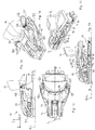
- a front unit of the exemplary embodiment of the invention is basically configured as a front part of a touring binding to pivotally hold a ski boot 12 on a front shoe section.
- the front unit comprises a base 14 which is provided for attachment to a touring ski and in particular fastening holes 16 (FIG. FIG. 4a ).
- the base 14 defines by its mounting arrangement for attachment to the sliding board a sliding board plane E corresponding to the surface of the sliding board on which the base 14 is to be mounted.
- a coordinate system of the front unit runs parallel to the Gleitbrettebene E and along a Gleitbrettlijnsachse L an X direction.
- Orthogonal to the X direction and also parallel to the sliding board plane E runs a Y direction (horizontally in the lateral direction).
- a Z-direction of the coordinate system of the front unit 10 extends vertically upward, i. orthogonal to the X direction and to the Y direction.
- the holding arrangement is held rotatably about the base 14 about a vertical axis V and comprises a main body 17, which is mounted rotatably on the base 14 about the axis V.
- the holding arrangement is arranged with a left engagement element 18l and a right engagement element 18r, which are each mounted on bearing portions 20l, 20r pivotally mounted on the base 14.
- the engagement elements 18l, 18r are each rotatable about vertical (in the Z direction) axes S1l, S1r.
- the engagement members 18l, 18r respectively carry coupling means 22l, 22r adapted to engage mating counter coupling means 24l, 24r at front left and right side portions of a sole 26 of the ski boot 12, respectively to pivotally hold the shoe 12 on the front unit 10 about a transverse axis Q defined by the two coupling means 22l, 22r, transverse to the X direction (in particular in the Y direction).
- a left link 28l is pivotally mounted on a left second pivot axis S2l, which is located at a distance from the left first pivot axis S1l.
- a right link 28r is pivotally mounted on a right second pivot axis S2r on the right engagement element 18r, wherein also the second right pivot axis S2r is at a distance from the right first pivot axis S1r.
- the connecting members 28l, 28r are each pivotally coupled to a clamping element 30. This coupling may be provided at a common pivot point.
- the left link 28l is pivotally hinged to the clamping element 30 on a left third pivot axis S3l and the right link 28r is pivoted on a right third pivot axis S3r on the clamping element 30, wherein the left and right third pivot axes S3l, S3r from each other and from the left and right second pivot axes S2l, S2r each have a distance.
- the pivot axes S1l, S1r, S2l, S2r and S3l, S3r are all parallel to one another, in particular in the Z direction.
- the tensioning element 30 can be held displaceably in the X direction on the front unit 10 and can be prestressed by a spring element 32 in a direction of displacement (here in the rearward direction or towards the shoe 12).
- the clamping element 30 is formed as a piston which is displaceably held on a piston guide 34 which is fixed to the base body 17.
- the spring 32 which biases the clamping element 30, may be supported at its front end on a spring bearing 36 of the piston guide 34 and be supported at its rear end on the clamping element 30.
- the spring bearing 36 may be held in threaded engagement with the piston guide 34, for example, be formed by a screw screwed into the piston guide 34, so that a bias of the spring 32 can be adjusted by turning the spring bearing 36.
- the holding arrangement further comprises an adjusting element 38 which can act on the clamping element 30 in order to displace the clamping element 30 against the force of the spring 32 so that the engagement elements 18l, 18r are moved into the release position.
- the adjusting element 38 can in particular be operated manually by the user, for example by exerting a compressive force by a ski pole, for which purpose the adjusting element 38 can have an operating section with a corresponding recess 40.
- the adjusting element 38 may be pivotally supported on the main body 17 and have a latching portion 42 which slides on movement of the adjusting element 38 on a control contour 44 of the clamping element 30 so that the movement of the adjusting element 38 in a displacement of the clamping element 30 against the force of the spring 32nd is implemented.
- the latching section 42 can be formed by a projection which engages in a recess forming the counter-latching section 46.
- an entry element 48 is further movably held, which has a pedal portion 50 for pressure actuation by a lower sole portion of a ski boot 12, so by such Pressure operation by the shoe 12 when entering the front unit 10, the entry element 48 is moved.
- An unlocking section 52 of the entry element 48 may be in communication with the adjustment element 38 such that movement of the entry element 48 due to the exertion of a compressive force from the shoe 12 to the pedal section 50 releases the latching section 42 of the adjustment element 38 from the counter-latching section 46 of the tensioning element 30, so that the Clamping element 30 is displaced by the force of the spring 32 and the engagement elements 18l, 18r pivot into the engaged position.
- the entry element 48 is pivotally mounted on the base body 17 at a pivot axis 54 pointing in the Y direction, so that an upward movement of the unlocking section 52 can be generated by the ski boot 12 acting downward (arrow 55) in order to lift the adjustment element 38 upwards and thus release the tensioning element 30.
- the holding device may further include a trigger lever 56 for providing a My-triggering mechanism.
- the release lever 56 may be pivotally mounted about a pivot axis 57 pointing in the Y direction on the base body 17 and be arranged so that a lower abutment portion 58 of the trigger lever 56 can be supported on an upper abutment portion 60 of the adjustment 38, so when exerting a compressive force the trigger lever 56 in Z-direction down and downward pivoting movement of the trigger lever 56 takes place a downward movement of the adjusting element 38, whereby the clamping element 30 is displaced against the force of the spring 32 and the engagement elements 18l, 18r are pivoted from the engaged position in the direction of release position.
- the trigger lever 56 preferably has an actuating portion 60, which is arranged in a pivoting range M of the shoe 12 with respect to a pivotal movement of the shoe 12 about the transverse axis Q of the coupling means 22l, 22r.
- the operating portion 60 of the trigger lever 56 in the down position of the front unit 10 eg FIGS. 2a to 2e ) positioned such that during a pivoting movement of Shoe 12 around the transverse axis Q forward strikes a front side 62 of the shoe 12 from above on the actuating portion 60 and pushes the trigger lever 56 on continuation of the pivoting movement down and thus opens in the manner described above, the holding device and the shoe 12 releases.
- Gleitbrett Mandarin which are set up and provided for use with a front unit of the type in question here, in particular already known touring ski boots, have a largely normalized geometry in the shoe tip, in particular the coupling to the known coupling pin (coupling means 22l, 22r), the position of the trigger portion 60 and the pivotal range of the trigger lever 56 may be suitably selected by a person skilled in the art to ensure reliable operation of the trigger mechanism during forward pivoting of the shoe 12 by such shoes.
- the front unit 10 of the embodiment of the invention may further relieve at least one of the two engagement members 18l, 18r by a relief portion.
- a left relief portion 64l is provided on the body 17 at which the left engaging member 18l can be supported vertically upward and downward
- a right relief portion 64r is fixed to the body 17 at which the right engaging member 18r in FIG can support vertical direction up and down.
- the left-hand relief section 64l will be described in more detail below, wherein the described features can also be provided analogously for the support on the right-hand relief section 64r.
- the left relief portion 64l has an upper relief surface 66o on which a lower support surface 68u of the left engagement member 18l can be supported, and further includes a lower relief surface 66u on which an upper support surface 68o of the left engagement member 18l can be supported, so that in vertical Direction of the engaging member 18l forces acting both upwards and downwards down stable in the discharge section 64l can be initiated.
- Upper and lower support surfaces 68o, 68u are arranged in a portion of the engagement element 18l, which is located between the bearing portion 20l and the coupling means 22l.
- the relief described above is realized by the positive engagement of a projection in a matching recess.
- the left relief portion 64l and the corresponding portion of the left engaging member 18l engage each other in a form-fitting, so that vertical forces can be stably absorbed.
- a projection 70 of the relief portion 64l may engage a mating recess 72 of the engagement member 18l or / and a projection 74 of the engagement member 18l may mate with a mating recess 76 of the relief portion 64l.
- the respective upper and lower support surfaces or relief surfaces are preferably parallel to the sliding board plane E, so that the pivoting movement of the engagement member 18l is not hindered and even during this pivotal movement the corresponding surfaces slide adjacent to each other and the relief function is provided even in intermediate states between engagement position and release position.
- the base body 17 comprises a plate-shaped portion with a circular bearing recess 78 (FIG. FIG. 3e ), wherein the edge portion of the bearing recess 78 is held under a peripheral edge portion 80 of a bearing plate 82 to be secured to the ski or base 14, so that the base body 17 can not be lifted off the gliding board or base 14, but around the central, in Z-direction extending axis of rotation V, which runs through the center of the bearing recess 78, is held rotatable. Since the holding arrangement, including the engaging member 18l, 18r, the clamping member 30 and the other coupled with these elements components are directly or indirectly held on the base body 17, the holding assembly can rotate together with an optionally held by this shoe 12 about the axis of rotation V.
- the rotational movement of the support assembly about the axis V is translated into an opening movement of the engagement members 18l, 18r to provide reliable Mz initiation.
- the control cam mechanism to be described below can be used.
- the control cam mechanism comprises a cam section 84 formed on the base-fixed bearing plate 82 with a left-hand cam surface 84l and a right-hand cam surface 84r, which can each be rectilinear and in particular symmetrical and V-shaped with respect to the longitudinal slide-board axis L.
- the cam portion 84 cooperates with a cam follower 86 which is movably held on the base body 17 and which is preferably biased by spring force into abutting contact with the cam portion 84.
- the biasing element 30 described above may include the cam follower 86 such that the spring means 32 may be used to bias the cam follower 86.
- the cam follower 86 may in particular be a projection on the rear end of the tensioning element 30.
- the contour of the cam portion 84 defines a neutral position according to FIG. 4a for the rotation of the base body 17 about the axis V, wherein in the neutral position of the cam follower 86 is disposed at a lowest point of the contour of the cam portion 84 and a pivotal movement of the base body 17 starting from the neutral position in both directions of rotation of the cam follower 86 each on one of two cam surfaces 84l, 84r of the cam portion 84 must accumulate and pushed back against the force of the cam follower 86 biasing spring becomes.
- a rotation of the main body 17 from the neutral position thus takes place against the resistance of an elastic restoring force.
- the neutral position is the normal driving position, in which a held on the holding arrangement ski boot 12 is aligned in the direction of Gleitbrettl Kunststoffsachse L.
- the front unit 10 of the embodiment of the present invention may further include a twist-lock mechanism which prevents rotation of the main body 17 and thus the holding assembly about the rotation axis V in a touring position of the front unit 10.
- the release lever 56 can be used to produce such a rotation lock.
- the trigger lever 56 can be adjusted by manual operation by the user about its pivot axis 57 so far forward until a Drehverriegelungsabexcellent 88 of the trigger lever 56 engages with an associated Drehverriegelungsabterrorism 90 of the base member 14 or the sliding board, so that a lateral movement between trip lever 56 and base 14 and sliding board is blocked and thus a rotational lock of the body 17 is reached.
- the rotational locking portion 88 of the trigger lever 56 engage in a matching recess 92 of the base member 14 to ensure a simple means a positive locking of both directions of rotation.
- the forward pivoting of the trigger lever 56 for rotational locking and the actuating portion 60 of the trigger lever 56 is removed from the pivoting range of the ski boot 12 so that in the tour position thus produced actuation of the trigger lever 56 is avoided by the shoe 12 and thus undesirable opening of the holding assembly in the tour position can be prevented.
- the clamping element 30 is moved against the force of the spring means 32 forward and is held in this position by engagement of the locking portion 42 with the counter-latching portion 46.
- the engagement elements 18l, 18r are pivoted to the open position, so that the coupling means 22l, 22r have a sufficiently large distance from each other, so that the ski boot 12 can be inserted between the coupling means 22l, 22r.
- the release lever 56 is folded back, so that the operation portion 60 is disposed in the vicinity of the ski boot 12.
- a rear edge portion 94 of the trigger lever 56 may in particular be positioned so that it serves as a stop or at least as an orientation for the ski boot 12 to arrange the ski boot 12 in a suitable position, so that the negative feedback means 24l, 24r of the ski boot 12 the coupling means 22l, 22r ready to attack each other.
- a moving path of the tension member 30 which runs along the sliding board longitudinal axis L is denoted by L 1
- a connecting line between the left second pivot axis S 21 and the left third pivot axis S 31 is denoted L 2
- a connecting line between the left second one S2l pivot axis and the left first pivot axis S1l is denoted by L. 3
- an angle W 1 between line L 1 and line L 2 is approximately a right angle and an angle W 2 between the line L 2 and L 3 is also substantially a right angle.
- cam follower 86 at the rear end of the clamping member 30 is not fully in abutting contact with the cam portion 84. Instead, a slight gap or clearance remains between cam follower 86 and cam portion 84. This play ensures that the coupling means 22l, 22r are pressed against the counter-coupling means 24l, 24r of the ski boot 12 under the spring tension resulting from the spring 32 and also at Manufacturing tolerances or wear are still held securely in contact with the system.
- an additional centering mechanism 96 may preferably be provided which causes the body 17 to be biased toward neutral, ie operate in an angular range in which, due to said play, therebetween Cam follower 86 and cam portion 84 a centering action by the cam mechanism 84, 86 is not effective.
- the additional centering mechanism 96 may be provided by two relatively weak springs 98 biasing the body 17 in opposite directions of rotation, such that upon deflection of the body 17 from the neutral position, either one or the other spring is compressed and forces back the body toward neutral ,
- the front unit 10 may be used for a downhill run.
- a heel portion of the ski boot 12 can be held by a heel unit, not shown, the touring binding.
- the front unit 10 of the embodiment provides a My-triggering mechanism and an Mz-triggering mechanism.
- the heel unit triggers in the lateral direction and the ski boot 12 pivots together with the holding assembly on the base body 16 about the vertical axis V.
- the cam follower slides 86 on one of the two control surfaces 84l, 84r of the cam portion 84, so that the clamping element 30 is pushed against the force of the spring means 32 forward.
- the clamping element 30 pivots the connecting members 28l, 28r and, as a consequence thereof, the engagement elements 18l, 18r in the direction of the release position.
- the heel unit (not shown) of the touring binding releases the heel portion of the ski boot 12 in a vertical upward direction when a force exceeding a predetermined release force acts on the ski boot in the sense of a rotational movement about the Y axis (eg during a fall).
- the ski boot 12 then rotates about the transverse axis Q of the coupling means 22l, 22r upward in the direction of a vertical position of the ski boot until the front 62 of the ski boot 12 contacts the actuating portion 60 of the trigger lever 56 from above.
- the release lever 56 is pressed down, so that the adjusting element 38 is also moved downward.
- the clamping element 30 By sliding the latching portion 42 on the control contour 44, the clamping element 30 is displaced in the forward direction against the force of the spring means 32 and adjusted in the manner described above, the engagement elements 18l, 18r in the release position, so that the ski boot 12 released from the front unit 10 becomes.
- a heel unit (not shown) of the touring binding can be adjusted so that it releases the heel portion of the ski boot 12, so that the ski boot 12 can pivot freely about the transverse axis Q.
- the front unit 10 in the tour position of the release lever 56 are folded forward until it is supported on the base member 14 or on the sliding board.
- the rotational locking portion 88 of the trigger lever 56 comes into locking engagement with the corresponding rotational locking portion 90 on the base part 14 and on the sliding board, so that rotation of the base body 17 is blocked about the axis V.
- the actuating portion 60 outside of Pivoting range M of the ski boot 12 arranged so that the ski boot 12 can pivot freely without actuation of the trigger lever 56 forward.
- the user can move the front unit 10 from the tour position as well as from the downhill to the release position.
- the user can exert a pressure force on the adjusting element 38 by means of a ski pole or in another way.
- the user in the downhill position of the front unit 10 exert a compressive force on the release lever 56.
- the tensioning element 30 is displaced forward in the manner already described above and the engagement elements 18l, 18r are moved into the release position until the latching section 42 locks with the counter-latching section 46 and the retaining arrangement is locked in the release position ,
- the coupling means 22l, 22r are then sufficiently far away from each other so that their engagement with the counter coupling means 24l, 24r is released and the ski boot 12 can be lifted off the front unit 10.
Landscapes
- Footwear And Its Accessory, Manufacturing Method And Apparatuses (AREA)
- Clamps And Clips (AREA)
- Holders For Apparel And Elements Relating To Apparel (AREA)
- Feeding Of Articles By Means Other Than Belts Or Rollers (AREA)
Claims (7)
- Unité avant (10) pour une fixation de randonnée, comprenant une base (14) agencée pour la fixation à une planche de glisse, qui définit un plan de planche de glisse (E), ainsi qu'un dispositif de maintien avant pour maintenir une section avant d'une chaussure de planche de glisse (12), qui comprend un élément d'engagement gauche (18l) et un élément d'engagement droit (18r), lesquels sont maintenus à chaque fois sur des sections d'appui (20l, 20r) de sorte qu'ils peuvent être déplacés entre une position d'engagement pour maintenir une chaussure de planche de glisse (12) et une position de déblocage pour débloquer une chaussure de planche de glisse (12),
dans laquelle les éléments d'engagement (18l, 18r) présentent des moyens de couplage (22l, 22r) à une section distante des sections d'appui (20l, 20r), qui sont agencés pour le couplage à des moyens de contre-couplage gauche et droit avant (24l, 24r) d'une chaussure de planche de glisse (12), et
dans laquelle les moyens de couplage (22l, 22r) définissent un axe transversal (Q) passant transversalement à un axe longitudinal de planche de glisse (L), autour duquel peut pivoter une chaussure de planche de glisse (12) maintenue sur les moyens de couplage (22l, 22r),
dans laquelle le dispositif de maintien avant est logé de façon rotative sur la base (14) pour permettre, dans une position d'engagement du dispositif de maintien avant, une rotation non seulement du dispositif de maintien avant mais aussi de la chaussure de planche de glisse (12) autour d'un axe vertical (V) commun, passant essentiellement orthogonalement au plan de planche de glisse (E), et
dans laquelle l'unité avant (10) comprend en outre un mécanisme de verrouillage tournant, lequel empêche une torsion du dispositif de maintien avant autour de l'axe vertical (V) dans une position de randonnée de la fixation de randonnée,
caractérisée en ce que l'unité avant (10) comprend en outre un dispositif de déclenchement (84, 86), lequel transforme un mouvement rotatif du dispositif de maintien avant par rapport à la base (14) autour de l'axe vertical (V) en un mouvement de déplacement du dispositif de maintien avant de la position d'engagement à une position de déblocage, dans lequel le mouvement rotatif est transformé en soi dans le mouvement d'ouverture du dispositif de maintien, de sorte que le processus d'ouverture est directement simultané au mouvement rotatif, dans laquelle le dispositif de déclenchement (84, 86) présente un mécanisme formant came de commande. - Unité avant (10) selon la revendication 1, caractérisée en ce que la base (14, 82) présente une section formant came (84) et en ce que le dispositif de maintien avant présente un organe suiveur de came (86), lequel est pressé en position par une force d'un dispositif tendeur (32) contre la section formant came (84), dans laquelle un mouvement de l'organe suiveur de came (86) à l'encontre de la force du dispositif tendeur (32) provoque le mouvement de déplacement du dispositif de maintien avant de la position d'engagement à la position de déblocage.
- Unité avant (10) selon la revendication 2, caractérisée en ce que la section formant came (84) présente un contour de commande en forme de V ou en forme de U, sur lequel le suiveur de came (86) lors d'une rotation relative est dévié entre le dispositif de maintien avant et la base (14).
- Unité avant (10) selon l'une des revendications précédentes, dans laquelle la chaussure de planche de glisse (12) peut pivoter, au moyen du dispositif de maintien avant, autour d'un axe (Q) passant transversalement à un axe longitudinal de planche de glisse (L) dans une zone de pivotement définie (M) entre une position horizontale, essentiellement en parallèle à un plan de planche de glisse (E), et une position inclinée selon un angle oblique par rapport au plan de la planche de glisse (E),
dans laquelle l'unité avant (10) comprend un dispositif d'actionnement (56, 30, 38) pour déplacer le dispositif de maintien avant entre la position d'engagement et une position de déblocage, dans laquelle la chaussure de planche de glisse (12) est essentiellement libérée de l'engagement de maintien du dispositif de maintien et
dans laquelle le dispositif d'actionnement (56, 30, 38) présente un élément d'actionnement (56), lequel est disposé dans la zone de pivotement (M), de sorte qu'une chaussure de planche de glisse (12) maintenue dans la position d'engagement touche l'élément d'actionnement, lors d'un mouvement de pivotement dans un sens de la position horizontale à la position inclinée, et actionne celui-ci pour le déplacement du dispositif de maintien dans la position de déblocage. - Unité avant (10) selon la revendication 4, caractérisée en ce que l'unité avant (10) est déplaçable entre une position de descente, dans laquelle l'élément d'actionnement (56) du dispositif d'actionnement est disposé dans la zone de pivotement (M), et une position de randonnée, dans laquelle l'élément d'actionnement (56) du dispositif d'actionnement est disposé à l'extérieur de la zone de pivotement (M).
- Unité avant (10) selon la revendication 5, caractérisée en ce que l'unité avant (10) présente un mécanisme de déclenchement (84, 86), dans laquelle le mécanisme de déclenchement (84, 86)
dans la position de descente est déplacé ou peut être déplacé dans une position active de sorte que, lors de l'action d'une force excédant une force de déclenchement prédéterminée entre la chaussure de planche de glisse (12) et l'unité avant (10), le dispositif de maintien est déplacé dans la position de déblocage afin de libérer la chaussure de planche de glisse (12) de l'unité avant (10),
dans laquelle le mécanisme de déclenchement (84, 86) se déplace ou peut être déplacé dans une position verrouillée (88, 90) dans la position de randonnée, de sorte qu'un dégagement de la chaussure de planche de glisse (12) est empêché, et
dans laquelle un déplacement de l'élément d'actionnement (56) de la position de descente à la position de randonnée provoque un déplacement du mécanisme de déclenchement (84, 86) de la position active à la position verrouillée (88, 90). - Unité avant (10) selon l'une des revendications précédentes, caractérisée en ce que l'unité avant (10) est agencée dans une position de descente afin de maintenir la chaussure de planche de glisse (12) en pivotement autour d'un axe essentiellement vertical (V).
Applications Claiming Priority (1)
| Application Number | Priority Date | Filing Date | Title |
|---|---|---|---|
| DE102012206880A DE102012206880A1 (de) | 2012-04-25 | 2012-04-25 | Vordereinheit für eine Gleitbrettbindung, insbesondere schwenkbare Vordereinheit mit Auslöseanordnung |
Publications (3)
| Publication Number | Publication Date |
|---|---|
| EP2656885A2 EP2656885A2 (fr) | 2013-10-30 |
| EP2656885A3 EP2656885A3 (fr) | 2014-02-19 |
| EP2656885B1 true EP2656885B1 (fr) | 2018-10-10 |
Family
ID=48182809
Family Applications (1)
| Application Number | Title | Priority Date | Filing Date |
|---|---|---|---|
| EP13165236.4A Active EP2656885B1 (fr) | 2012-04-25 | 2013-04-24 | Unité avant pour la fixation d'une planche de glisse, notamment unité avant pivotante dotée d'un dispositif de déclenchement |
Country Status (3)
| Country | Link |
|---|---|
| US (1) | US8807586B2 (fr) |
| EP (1) | EP2656885B1 (fr) |
| DE (1) | DE102012206880A1 (fr) |
Families Citing this family (8)
| Publication number | Priority date | Publication date | Assignee | Title |
|---|---|---|---|---|
| ITTO20110598A1 (it) * | 2011-07-07 | 2013-01-08 | Elmi S R L | Puntale per attacco da sci o racchette da neve con sistema autocentrante magnetico |
| FR3002460B1 (fr) * | 2013-02-22 | 2017-08-25 | Rossignol Sa | Butee a declenchement automatique en torsion |
| DE102013003839A1 (de) * | 2013-03-07 | 2014-09-11 | Reinhold Zoor | Pin-Vorderbacken mit horizontalgelagerten Auslösebacken |
| DE102013009762A1 (de) * | 2013-06-10 | 2014-12-11 | Andreas Allmann | Sicherheitsskibindungssystem |
| EP2929918B1 (fr) | 2014-04-09 | 2018-05-23 | Salomon S.A.S. | Fixation de ski |
| FR3019758B1 (fr) * | 2014-04-09 | 2016-05-13 | Salomon Sas | Fixation de ski |
| EP3266504A1 (fr) * | 2016-07-07 | 2018-01-10 | Fritschi AG - Swiss Bindings | Fixation de ski |
| DE102020116389B8 (de) | 2020-06-22 | 2026-06-25 | Salewa Sport Ag | Vordereinheit für eine Tourenbindung mit Längspositionierabschnitt |
Citations (1)
| Publication number | Priority date | Publication date | Assignee | Title |
|---|---|---|---|---|
| EP2431080A1 (fr) * | 2010-09-16 | 2012-03-21 | Salewa Sport AG | Fixation de planche de glisse, notamment fixation de ski de fond |
Family Cites Families (14)
| Publication number | Priority date | Publication date | Assignee | Title |
|---|---|---|---|---|
| DE2907359A1 (de) * | 1979-02-24 | 1980-08-28 | Ver Baubeschlag Gretsch Co | Langlauf-sicherheitsskibindung |
| AT381458B (de) | 1985-03-25 | 1986-10-27 | Barthel Fritz | Tourenskibindung |
| FR2662090B1 (fr) * | 1990-05-21 | 1994-10-21 | Salomon Sa | Fixation de securite pour ski de fond. |
| IT1250894B (it) * | 1991-12-24 | 1995-04-21 | Fiat Auto Spa | Serbatoio di carburante per autoveicoli e procedimenti per realizzarlo |
| US5544909A (en) * | 1994-01-27 | 1996-08-13 | The Burton Corporation | Step-in boot binding |
| DE19703942C2 (de) * | 1997-02-03 | 1999-03-11 | Carl Franz | Schibindung |
| US7318598B2 (en) * | 2003-02-18 | 2008-01-15 | Kneebinding Inc. | Alpine ski binding heel unit |
| US7490859B2 (en) * | 2005-06-24 | 2009-02-17 | Skis Rossignol Sa | Device for retaining a boot on a snowboard |
| FR2899121B1 (fr) * | 2006-03-29 | 2008-07-04 | Salomon Sa | Ensemble ski de fond et dispositif de fixation de ski de fond |
| AT505127A1 (de) | 2007-05-10 | 2008-11-15 | Fleck Carl M Dr | Wall-flow-filter mit geringem druckaufbau |
| US8439389B2 (en) * | 2008-04-03 | 2013-05-14 | G3 Genuine Guide Gear Inc. | Toe unit for alpine touring binding |
| DE102010001603A1 (de) * | 2010-02-04 | 2011-08-04 | Salewa Sport Ag | Tourenskibindung mit Verriegelungsmechanismus |
| DE102010029647A1 (de) * | 2010-06-02 | 2011-12-08 | Salewa Sport Ag | Tourenbindung |
| CH705579A2 (de) | 2011-09-29 | 2013-04-15 | Fritschi Ag Swiss Bindings | Frontautomat. |
-
2012
- 2012-04-25 DE DE102012206880A patent/DE102012206880A1/de active Pending
-
2013
- 2013-04-24 EP EP13165236.4A patent/EP2656885B1/fr active Active
- 2013-04-25 US US13/870,019 patent/US8807586B2/en active Active
Patent Citations (1)
| Publication number | Priority date | Publication date | Assignee | Title |
|---|---|---|---|---|
| EP2431080A1 (fr) * | 2010-09-16 | 2012-03-21 | Salewa Sport AG | Fixation de planche de glisse, notamment fixation de ski de fond |
Also Published As
| Publication number | Publication date |
|---|---|
| US20130285352A1 (en) | 2013-10-31 |
| EP2656885A3 (fr) | 2014-02-19 |
| DE102012206880A1 (de) | 2013-10-31 |
| EP2656885A2 (fr) | 2013-10-30 |
| US8807586B2 (en) | 2014-08-19 |
Similar Documents
| Publication | Publication Date | Title |
|---|---|---|
| EP2656885A2 (fr) | Unité avant pour la fixation d'une planche de glisse, notamment unité avant pivotante dotée d'un dispositif de déclenchement | |
| EP2662121B1 (fr) | Butée avant d'une fixation de planche de glisse et fixation de planche de glisse | |
| DE1960002C3 (de) | Auslösende Skibindung mit einer verschwenkbaren Trittplatte | |
| EP2384794B1 (fr) | talonnière de fixation, notamment fixation de ski de randonnée | |
| AT515190B1 (de) | Ferseneinheit mit Bremsanordnung | |
| EP0069753B1 (fr) | Fixation de securite de ski | |
| EP2626117B1 (fr) | Unité avant pour la fixation d'une planche de glisse, fixation de ski de fond et fixation de saut à ski | |
| EP3566754B1 (fr) | Butée avant de fixation de ski | |
| DE202011110534U1 (de) | Tourenbindung | |
| EP2452731B1 (fr) | Fixation de randonnée dotée d'un mécanisme de déclenchement et d'un mécanisme de verrouillage | |
| EP2666525A1 (fr) | Talonnière avec cale de montée et ensemble stop-ski | |
| AT400407B (de) | Sicherheitsskibindung | |
| DE69401171T2 (de) | Bindungselement für einen alpinen Ski | |
| AT515189B1 (de) | Ferseneinheit für eine Tourenbindung und Tourenbindung | |
| EP3885010B1 (fr) | Talonniere de ski de randonnée pourvue de mécanisme de déclenchement et d'une possibilité de réglage sans efforts | |
| EP2865427B1 (fr) | Unité de talon pour une fixation de ski de randonée | |
| WO1990009821A1 (fr) | Machoire anterieure pour fixations de securite de skis | |
| EP3332843B1 (fr) | Unité de talon pour une fixation de planche de glisse dotée d'un systeme de frein | |
| EP2826528B1 (fr) | Unité avant d'une fixation de planche de glisse | |
| DE3202267A1 (de) | Fersenhalter einer skibindung mit skibremse | |
| EP0128243B1 (fr) | Fixation de ski à déclenchement | |
| EP0561008A1 (fr) | Dispositif de maintien du talon pour fixation de ski | |
| EP4257212B1 (fr) | Unité de talon pour une fixation de planche de glisse dotée d'un déclenchement mz par l'intermédiaire d'une came | |
| DE2907364C2 (fr) | ||
| EP0470419B1 (fr) | Fixation arrière de sécurité |
Legal Events
| Date | Code | Title | Description |
|---|---|---|---|
| PUAI | Public reference made under article 153(3) epc to a published international application that has entered the european phase |
Free format text: ORIGINAL CODE: 0009012 |
|
| AK | Designated contracting states |
Kind code of ref document: A2 Designated state(s): AL AT BE BG CH CY CZ DE DK EE ES FI FR GB GR HR HU IE IS IT LI LT LU LV MC MK MT NL NO PL PT RO RS SE SI SK SM TR |
|
| AX | Request for extension of the european patent |
Extension state: BA ME |
|
| RIC1 | Information provided on ipc code assigned before grant |
Ipc: A63C 9/086 20120101ALI20131024BHEP Ipc: A63C 9/085 20120101ALI20131024BHEP Ipc: A63C 9/08 20120101AFI20131024BHEP |
|
| PUAL | Search report despatched |
Free format text: ORIGINAL CODE: 0009013 |
|
| AK | Designated contracting states |
Kind code of ref document: A3 Designated state(s): AL AT BE BG CH CY CZ DE DK EE ES FI FR GB GR HR HU IE IS IT LI LT LU LV MC MK MT NL NO PL PT RO RS SE SI SK SM TR |
|
| AX | Request for extension of the european patent |
Extension state: BA ME |
|
| RIC1 | Information provided on ipc code assigned before grant |
Ipc: A63C 9/085 20120101ALI20140110BHEP Ipc: A63C 9/086 20120101ALI20140110BHEP Ipc: A63C 9/08 20120101AFI20140110BHEP |
|
| 17P | Request for examination filed |
Effective date: 20140710 |
|
| RBV | Designated contracting states (corrected) |
Designated state(s): AL AT BE BG CH CY CZ DE DK EE ES FI FR GB GR HR HU IE IS IT LI LT LU LV MC MK MT NL NO PL PT RO RS SE SI SK SM TR |
|
| 17Q | First examination report despatched |
Effective date: 20151126 |
|
| STAA | Information on the status of an ep patent application or granted ep patent |
Free format text: STATUS: EXAMINATION IS IN PROGRESS |
|
| GRAP | Despatch of communication of intention to grant a patent |
Free format text: ORIGINAL CODE: EPIDOSNIGR1 |
|
| STAA | Information on the status of an ep patent application or granted ep patent |
Free format text: STATUS: GRANT OF PATENT IS INTENDED |
|
| INTG | Intention to grant announced |
Effective date: 20180418 |
|
| GRAS | Grant fee paid |
Free format text: ORIGINAL CODE: EPIDOSNIGR3 |
|
| GRAA | (expected) grant |
Free format text: ORIGINAL CODE: 0009210 |
|
| STAA | Information on the status of an ep patent application or granted ep patent |
Free format text: STATUS: THE PATENT HAS BEEN GRANTED |
|
| AK | Designated contracting states |
Kind code of ref document: B1 Designated state(s): AL AT BE BG CH CY CZ DE DK EE ES FI FR GB GR HR HU IE IS IT LI LT LU LV MC MK MT NL NO PL PT RO RS SE SI SK SM TR |
|
| REG | Reference to a national code |
Ref country code: GB Ref legal event code: FG4D Free format text: NOT ENGLISH |
|
| REG | Reference to a national code |
Ref country code: CH Ref legal event code: EP Ref country code: AT Ref legal event code: REF Ref document number: 1050568 Country of ref document: AT Kind code of ref document: T Effective date: 20181015 |
|
| REG | Reference to a national code |
Ref country code: IE Ref legal event code: FG4D Free format text: LANGUAGE OF EP DOCUMENT: GERMAN |
|
| REG | Reference to a national code |
Ref country code: DE Ref legal event code: R096 Ref document number: 502013011267 Country of ref document: DE |
|
| REG | Reference to a national code |
Ref country code: NL Ref legal event code: MP Effective date: 20181010 |
|
| REG | Reference to a national code |
Ref country code: LT Ref legal event code: MG4D |
|
| PG25 | Lapsed in a contracting state [announced via postgrant information from national office to epo] |
Ref country code: NL Free format text: LAPSE BECAUSE OF FAILURE TO SUBMIT A TRANSLATION OF THE DESCRIPTION OR TO PAY THE FEE WITHIN THE PRESCRIBED TIME-LIMIT Effective date: 20181010 |
|
| PG25 | Lapsed in a contracting state [announced via postgrant information from national office to epo] |
Ref country code: LV Free format text: LAPSE BECAUSE OF FAILURE TO SUBMIT A TRANSLATION OF THE DESCRIPTION OR TO PAY THE FEE WITHIN THE PRESCRIBED TIME-LIMIT Effective date: 20181010 Ref country code: HR Free format text: LAPSE BECAUSE OF FAILURE TO SUBMIT A TRANSLATION OF THE DESCRIPTION OR TO PAY THE FEE WITHIN THE PRESCRIBED TIME-LIMIT Effective date: 20181010 Ref country code: ES Free format text: LAPSE BECAUSE OF FAILURE TO SUBMIT A TRANSLATION OF THE DESCRIPTION OR TO PAY THE FEE WITHIN THE PRESCRIBED TIME-LIMIT Effective date: 20181010 Ref country code: PL Free format text: LAPSE BECAUSE OF FAILURE TO SUBMIT A TRANSLATION OF THE DESCRIPTION OR TO PAY THE FEE WITHIN THE PRESCRIBED TIME-LIMIT Effective date: 20181010 Ref country code: BG Free format text: LAPSE BECAUSE OF FAILURE TO SUBMIT A TRANSLATION OF THE DESCRIPTION OR TO PAY THE FEE WITHIN THE PRESCRIBED TIME-LIMIT Effective date: 20190110 Ref country code: LT Free format text: LAPSE BECAUSE OF FAILURE TO SUBMIT A TRANSLATION OF THE DESCRIPTION OR TO PAY THE FEE WITHIN THE PRESCRIBED TIME-LIMIT Effective date: 20181010 Ref country code: FI Free format text: LAPSE BECAUSE OF FAILURE TO SUBMIT A TRANSLATION OF THE DESCRIPTION OR TO PAY THE FEE WITHIN THE PRESCRIBED TIME-LIMIT Effective date: 20181010 Ref country code: NO Free format text: LAPSE BECAUSE OF FAILURE TO SUBMIT A TRANSLATION OF THE DESCRIPTION OR TO PAY THE FEE WITHIN THE PRESCRIBED TIME-LIMIT Effective date: 20190110 Ref country code: IS Free format text: LAPSE BECAUSE OF FAILURE TO SUBMIT A TRANSLATION OF THE DESCRIPTION OR TO PAY THE FEE WITHIN THE PRESCRIBED TIME-LIMIT Effective date: 20190210 |
|
| PG25 | Lapsed in a contracting state [announced via postgrant information from national office to epo] |
Ref country code: AL Free format text: LAPSE BECAUSE OF FAILURE TO SUBMIT A TRANSLATION OF THE DESCRIPTION OR TO PAY THE FEE WITHIN THE PRESCRIBED TIME-LIMIT Effective date: 20181010 Ref country code: SE Free format text: LAPSE BECAUSE OF FAILURE TO SUBMIT A TRANSLATION OF THE DESCRIPTION OR TO PAY THE FEE WITHIN THE PRESCRIBED TIME-LIMIT Effective date: 20181010 Ref country code: GR Free format text: LAPSE BECAUSE OF FAILURE TO SUBMIT A TRANSLATION OF THE DESCRIPTION OR TO PAY THE FEE WITHIN THE PRESCRIBED TIME-LIMIT Effective date: 20190111 Ref country code: RS Free format text: LAPSE BECAUSE OF FAILURE TO SUBMIT A TRANSLATION OF THE DESCRIPTION OR TO PAY THE FEE WITHIN THE PRESCRIBED TIME-LIMIT Effective date: 20181010 Ref country code: PT Free format text: LAPSE BECAUSE OF FAILURE TO SUBMIT A TRANSLATION OF THE DESCRIPTION OR TO PAY THE FEE WITHIN THE PRESCRIBED TIME-LIMIT Effective date: 20190210 |
|
| REG | Reference to a national code |
Ref country code: DE Ref legal event code: R097 Ref document number: 502013011267 Country of ref document: DE |
|
| PG25 | Lapsed in a contracting state [announced via postgrant information from national office to epo] |
Ref country code: DK Free format text: LAPSE BECAUSE OF FAILURE TO SUBMIT A TRANSLATION OF THE DESCRIPTION OR TO PAY THE FEE WITHIN THE PRESCRIBED TIME-LIMIT Effective date: 20181010 Ref country code: IT Free format text: LAPSE BECAUSE OF FAILURE TO SUBMIT A TRANSLATION OF THE DESCRIPTION OR TO PAY THE FEE WITHIN THE PRESCRIBED TIME-LIMIT Effective date: 20181010 Ref country code: CZ Free format text: LAPSE BECAUSE OF FAILURE TO SUBMIT A TRANSLATION OF THE DESCRIPTION OR TO PAY THE FEE WITHIN THE PRESCRIBED TIME-LIMIT Effective date: 20181010 |
|
| PLBE | No opposition filed within time limit |
Free format text: ORIGINAL CODE: 0009261 |
|
| STAA | Information on the status of an ep patent application or granted ep patent |
Free format text: STATUS: NO OPPOSITION FILED WITHIN TIME LIMIT |
|
| PG25 | Lapsed in a contracting state [announced via postgrant information from national office to epo] |
Ref country code: RO Free format text: LAPSE BECAUSE OF FAILURE TO SUBMIT A TRANSLATION OF THE DESCRIPTION OR TO PAY THE FEE WITHIN THE PRESCRIBED TIME-LIMIT Effective date: 20181010 Ref country code: SK Free format text: LAPSE BECAUSE OF FAILURE TO SUBMIT A TRANSLATION OF THE DESCRIPTION OR TO PAY THE FEE WITHIN THE PRESCRIBED TIME-LIMIT Effective date: 20181010 Ref country code: EE Free format text: LAPSE BECAUSE OF FAILURE TO SUBMIT A TRANSLATION OF THE DESCRIPTION OR TO PAY THE FEE WITHIN THE PRESCRIBED TIME-LIMIT Effective date: 20181010 Ref country code: SM Free format text: LAPSE BECAUSE OF FAILURE TO SUBMIT A TRANSLATION OF THE DESCRIPTION OR TO PAY THE FEE WITHIN THE PRESCRIBED TIME-LIMIT Effective date: 20181010 |
|
| 26N | No opposition filed |
Effective date: 20190711 |
|
| PG25 | Lapsed in a contracting state [announced via postgrant information from national office to epo] |
Ref country code: SI Free format text: LAPSE BECAUSE OF FAILURE TO SUBMIT A TRANSLATION OF THE DESCRIPTION OR TO PAY THE FEE WITHIN THE PRESCRIBED TIME-LIMIT Effective date: 20181010 |
|
| REG | Reference to a national code |
Ref country code: CH Ref legal event code: PL |
|
| REG | Reference to a national code |
Ref country code: BE Ref legal event code: MM Effective date: 20190430 |
|
| GBPC | Gb: european patent ceased through non-payment of renewal fee |
Effective date: 20190424 |
|
| PG25 | Lapsed in a contracting state [announced via postgrant information from national office to epo] |
Ref country code: MC Free format text: LAPSE BECAUSE OF FAILURE TO SUBMIT A TRANSLATION OF THE DESCRIPTION OR TO PAY THE FEE WITHIN THE PRESCRIBED TIME-LIMIT Effective date: 20181010 Ref country code: LU Free format text: LAPSE BECAUSE OF NON-PAYMENT OF DUE FEES Effective date: 20190424 |
|
| PG25 | Lapsed in a contracting state [announced via postgrant information from national office to epo] |
Ref country code: GB Free format text: LAPSE BECAUSE OF NON-PAYMENT OF DUE FEES Effective date: 20190424 Ref country code: LI Free format text: LAPSE BECAUSE OF NON-PAYMENT OF DUE FEES Effective date: 20190430 Ref country code: CH Free format text: LAPSE BECAUSE OF NON-PAYMENT OF DUE FEES Effective date: 20190430 |
|
| PG25 | Lapsed in a contracting state [announced via postgrant information from national office to epo] |
Ref country code: FR Free format text: LAPSE BECAUSE OF NON-PAYMENT OF DUE FEES Effective date: 20190430 Ref country code: BE Free format text: LAPSE BECAUSE OF NON-PAYMENT OF DUE FEES Effective date: 20190430 |
|
| PG25 | Lapsed in a contracting state [announced via postgrant information from national office to epo] |
Ref country code: TR Free format text: LAPSE BECAUSE OF FAILURE TO SUBMIT A TRANSLATION OF THE DESCRIPTION OR TO PAY THE FEE WITHIN THE PRESCRIBED TIME-LIMIT Effective date: 20181010 |
|
| PG25 | Lapsed in a contracting state [announced via postgrant information from national office to epo] |
Ref country code: IE Free format text: LAPSE BECAUSE OF NON-PAYMENT OF DUE FEES Effective date: 20190424 |
|
| PG25 | Lapsed in a contracting state [announced via postgrant information from national office to epo] |
Ref country code: CY Free format text: LAPSE BECAUSE OF FAILURE TO SUBMIT A TRANSLATION OF THE DESCRIPTION OR TO PAY THE FEE WITHIN THE PRESCRIBED TIME-LIMIT Effective date: 20181010 |
|
| PG25 | Lapsed in a contracting state [announced via postgrant information from national office to epo] |
Ref country code: MT Free format text: LAPSE BECAUSE OF FAILURE TO SUBMIT A TRANSLATION OF THE DESCRIPTION OR TO PAY THE FEE WITHIN THE PRESCRIBED TIME-LIMIT Effective date: 20181010 Ref country code: HU Free format text: LAPSE BECAUSE OF FAILURE TO SUBMIT A TRANSLATION OF THE DESCRIPTION OR TO PAY THE FEE WITHIN THE PRESCRIBED TIME-LIMIT; INVALID AB INITIO Effective date: 20130424 |
|
| PG25 | Lapsed in a contracting state [announced via postgrant information from national office to epo] |
Ref country code: MK Free format text: LAPSE BECAUSE OF FAILURE TO SUBMIT A TRANSLATION OF THE DESCRIPTION OR TO PAY THE FEE WITHIN THE PRESCRIBED TIME-LIMIT Effective date: 20181010 |
|
| P02 | Opt-out of the competence of the unified patent court (upc) changed |
Effective date: 20230527 |
|
| PGFP | Annual fee paid to national office [announced via postgrant information from national office to epo] |
Ref country code: DE Payment date: 20260331 Year of fee payment: 14 |
|
| PGFP | Annual fee paid to national office [announced via postgrant information from national office to epo] |
Ref country code: AT Payment date: 20260421 Year of fee payment: 14 |