EP2656915B1 - Pipette destinée à actionner une seringue - Google Patents
Pipette destinée à actionner une seringue Download PDFInfo
- Publication number
- EP2656915B1 EP2656915B1 EP12002848.5A EP12002848A EP2656915B1 EP 2656915 B1 EP2656915 B1 EP 2656915B1 EP 12002848 A EP12002848 A EP 12002848A EP 2656915 B1 EP2656915 B1 EP 2656915B1
- Authority
- EP
- European Patent Office
- Prior art keywords
- housing
- lever
- pipette
- draw
- pipette according
- Prior art date
- Legal status (The legal status is an assumption and is not a legal conclusion. Google has not performed a legal analysis and makes no representation as to the accuracy of the status listed.)
- Active
Links
Images



Classifications
-
- B—PERFORMING OPERATIONS; TRANSPORTING
- B01—PHYSICAL OR CHEMICAL PROCESSES OR APPARATUS IN GENERAL
- B01L—CHEMICAL OR PHYSICAL LABORATORY APPARATUS FOR GENERAL USE
- B01L3/00—Containers or dishes for laboratory use, e.g. laboratory glassware; Droppers
- B01L3/02—Burettes; Pipettes
- B01L3/021—Pipettes, i.e. with only one conduit for withdrawing and redistributing liquids
- B01L3/0217—Pipettes, i.e. with only one conduit for withdrawing and redistributing liquids of the plunger pump type
- B01L3/0234—Repeating pipettes, i.e. for dispensing multiple doses from a single charge
-
- B—PERFORMING OPERATIONS; TRANSPORTING
- B01—PHYSICAL OR CHEMICAL PROCESSES OR APPARATUS IN GENERAL
- B01L—CHEMICAL OR PHYSICAL LABORATORY APPARATUS FOR GENERAL USE
- B01L2200/00—Solutions for specific problems relating to chemical or physical laboratory apparatus
- B01L2200/14—Process control and prevention of errors
- B01L2200/141—Preventing contamination, tampering
-
- B—PERFORMING OPERATIONS; TRANSPORTING
- B01—PHYSICAL OR CHEMICAL PROCESSES OR APPARATUS IN GENERAL
- B01L—CHEMICAL OR PHYSICAL LABORATORY APPARATUS FOR GENERAL USE
- B01L2300/00—Additional constructional details
- B01L2300/04—Closures and closing means
- B01L2300/041—Connecting closures to device or container
-
- B—PERFORMING OPERATIONS; TRANSPORTING
- B01—PHYSICAL OR CHEMICAL PROCESSES OR APPARATUS IN GENERAL
- B01L—CHEMICAL OR PHYSICAL LABORATORY APPARATUS FOR GENERAL USE
- B01L2300/00—Additional constructional details
- B01L2300/04—Closures and closing means
- B01L2300/041—Connecting closures to device or container
- B01L2300/044—Connecting closures to device or container pierceable, e.g. films, membranes
Definitions
- the invention relates to a pipette for actuating a syringe.
- the pipettes used here for actuating a syringe serve to dispense liquid received in the syringe in several steps. They are also referred to as dispensers or repeating pipettes. These pipettes have at the lower end of a rod-shaped housing a receptacle for a flange of a cylinder of the syringe and in the housing a displaceable receiving body with a piston receptacle for the upper end portion of a piston rod of a piston of the syringe.
- the syringe can be used with the flange and the end portion of the piston rod through axially directed openings of the receptacles.
- the flange and the end portion are held in the receptacles by means for detachable holding, which are designed, for example, as spring-loaded gripping levers.
- the pipette comprises means for displacing the receiving body, which allow a partial withdrawal of the piston from the cylinder for the suction of liquid into the syringe and a stepwise depression of the piston into the cylinder for the stepwise discharge of liquid.
- the DE 2926691 C2 and the US 4406170 A describe means for displacing the receiving body in the housing. These include a connected to the receiving body and by a straight line slot protruding from the housing elevator lever for drawing liquid into the syringe by displacing the receiving body of the recording away. In addition, they include a rack-pawl means for gradually advancing the piston by a reciprocating metering lever. At the metering a pivoting pawl is mounted. The rack is connected to the receiving body and arranged in the pivoting range of the pawl. An adjustable sliding cover covers the row of teeth on the rack more or less to the engagement of the To limit the pawl into the rack while swiveling the dosing lever.
- the rack is designed with a contour through which in the advanced position of the piston, the cover of the rack is displaced away, so that it prevents the pawl from engaging in the uncovered teeth of the rack. This prevents that a residual amount is discharged from the syringe, which is smaller than the dispensed in each dosing step dosage.
- the EP 0657216 B1 and US 5620661 A describe such a pipette with a sensor for sensing protrusions and depressions on the syringe flange and associated syringes.
- the sensor is used to determine the size of the syringe used.
- electronics Based on the set increment, electronics will determine the amount of fluid dispensed at each dispensing step. This will be shown on a display.
- the receiving body is firmly connected to a rigid cover strip, which covers the slot from the inside.
- the cover strip extends upwardly from the receiving body, so that it covers only the slot above the elevator lever. There is not enough room for another cover strip below the elevator lever.
- the cover strip shifts in the Housing up and the slot opens below the elevator lever,
- two elastic hoses which are arranged in the housing of the pipette.
- the open slot allows an insight into the interior of the device and dirt in the housing, which contaminates the mechanical and possibly electronic components of the pipette.
- the DE 32 11 271 A1 and EP 0 090 250 A1 describe a slider with slots on actuators for heating and ventilation, especially in air conditioning systems of motor vehicles.
- a band is attached, whose ends are attached to the body.
- the tape is passed through a breakthrough of an operating lever of the slider.
- the tape is spaced from the slot so that there is a cavity between the slot and tape that allows dirt to enter the body. The tape prevents the leakage of extraneous light from the slider while reducing contamination of the internal structure.
- the DE 195 41 628 C2 describes a sliding plate, for example, a sliding resistance or to change the bias of a spring in a mechanical system or in execution of a program selector lever for an automatic transmission in motor vehicles.
- the slide actuator has a housing having a slot and a sliding piece longitudinally movable in the slot with a driver side and a driver side mounted thereon and extending through the slot.
- the sliding plate has an exclusively in Slot direction extending, flexible band.
- the band passes over the slot in a groove on the side of the housing facing the pickup side and extends through a recess in the push piece. At its ends the band is fixed on the housing, wherein the distance of the fixing points is less than the length of the band extending therebetween.
- the tape seals the slot at the locations of the slot where the sliding piece is not located.
- the tape may be easily soiled and damaged due to its location on the outside of the housing.
- the recess in the sliding piece is formed in one embodiment by a laterally generated slot in the receiving side of the sliding piece.
- the lateral arrangement of the slot allows lateral leakage of the tape. It also affects the appearance of the sliding piece.
- the sliding piece is formed by two contiguous, substantially symmetrical halves, each consisting of one half of the transducer side and the driver side, wherein the recess by a respective slot in the contact surface of the two halves with a depth which is at least half corresponds to the width of the band is formed.
- the division of the sliding piece in two symmetrical halves requires a complex assembly, since the halves must be pushed onto the narrow sides of the tape. In addition, the appearance of the split sliding piece is impaired.
- the object of the invention is to provide a pipette for actuating a syringe with a sealed housing.
- the slot can always be covered by the cover strip, regardless of which position the receiving body occupies in the housing. This is achieved in that the cover strip the slot covered from below and held in the longitudinal direction of the slot spaced apart locations in the housing. At the two longitudinal sides of the slot, however, the cover strip has no connection with the housing.
- the connecting element is provided with a channel through which the cover strip extends.
- the friction between the means for displacing the receiving body and / or other components which can be displaced in the housing and which are connected to these means and components arranged fixedly in the housing is such that the elevator lever does not rotate when the pipette is oriented vertically moved independently along the slot.
- the friction brake prevents inadvertent displacement of the receiving body and the associated elevator lever, without the need for additional components for this purpose.
- the friction is dimensioned such that the elevator lever does not automatically move along the vertical axis of the pipette Schlitzes shifted. According to a preferred embodiment, the friction is so dimensioned that the elevator lever does not shift automatically even when the pipette is moved in vertical alignment by the user.
- the dimensioning of the friction is preferably based on the usual gentle movements of the user when picking up, carrying, using and depositing a pipette. The friction acting between the displaceable component and the component arranged fixedly in the housing prevents a displacement of the elevator lever along the slot under the influence of the weight force acting on the elevator lever and, if necessary, under the influence of acceleration forces.
- the friction is dimensioned such that the elevator lever does not automatically shift along the slot when the pipette is in a vertical position, even if the pipette is not equipped with a syringe. In this case, a displacement of the elevator lever is not counteracted by the friction between syringe plunger and syringe barrel.
- Another advantage of the invention is that by passing the cover strip through the channel, the friction between the movable member and the component fixedly disposed in the housing can be determined.
- the friction between the connecting element and cover strip is dimensioned so that the elevator lever does not automatically displaced along the slot in vertical alignment of the pipette or this friction is displaced together with the friction between another pair in the housing and fixedly arranged in the housing Dimension components accordingly.
- the friction between the cover strip and the connecting element depends in particular on the materials of the cover strip and connecting element, on the geometric shape and the dimensions of the channel and the cover strip and on the prestressing with which the cover strip is held in the housing is. These parameters can be set so that the friction meets the aforementioned criteria.
- the friction between another pair of components one of which is displaceable in the housing and the other is fixedly arranged in the housing, as the connecting element and the cover strip dimensioned so that the elevator lever does not automatically along the Schlitzes shifted.
- the pair of components may be, for example, a rack for displacing the receiving body within the housing and a bearing block fixedly connected to the housing for supporting a pivotable actuating lever of a pawl drive of the rack.
- these pairs of components may be the elevator lever which can be displaced relative to the housing or the connecting element and the housing itself.
- the friction between the displaceable component and the component permanently connected to the housing can also be dimensioned together with the friction between the connecting element and the cover strip such that the elevator lever does not automatically displace along the housing when the pipette is vertically aligned.
- the invention relates to rigid cover strips.
- the cover strip is flexible.
- a flexible cover strip or cover strip is preferably kept stretched between the two spaced apart in the longitudinal direction of the slot locations.
- the cover strip is elastic. Due to the elastic design, the cover strip can stretch, so that it does not tear when loaded in the longitudinal direction. A load of the cover strip in Longitudinal direction can be effected for example by a slight tilting of the elevator lever.
- the cover strip is flexible and has the channel in the connecting element in the longitudinal direction of the cover strip a flat U-shaped curved course, so that the cover strip is deflected in the channel of a plane in which it extends adjacent to the connecting element.
- the U-shaped course of the channel favors a close contact of the flexible cover strip at the edges of the slot, because the upper boundary of the channel can be displaced away from the edges of the slot.
- the close contact of the flexible cover strip at the edges of the slot penetration of dirt into the housing is effectively prevented.
- the flexible cover strip is curved on both sides of the connecting element to the edges of the slot through the shape of the channel. Due to the deflection of the cover strip in the channel, the friction between the cover strip and connecting element is increased, which counteracts an unintentional displacement of the receiving body in the housing.
- the channel runs in the connecting element with its mouths curved in the plane through the undeflected portions of the cover strip.
- the receiving body is fixedly connected to at least one support member which is supported on a support track in the housing, which is aligned parallel to the plane through the portions of the cover strip outside of the connecting element. Be about support element and support track Forces acting on the elevator lever derived in the housing. An overload of the cover strip is thereby avoided.
- the support elements are wings projecting on different sides of the receiving body in a plane which is parallel to the plane in which the cover strip is arranged adjacent to the connecting element and which are in parallel grooves on the inside of the opposite walls of the housing intervention. About the wings uniform support and guidance of the receiving body is achieved in the housing.
- the connecting element has a slot nut engaging in the slot.
- the nut may guide the connector in the slot.
- the connecting element has a fixed to the receiving body, arranged in the housing elevator lever holder and a slot through and connected to the elevator lever elevator lever carrier, wherein the channel between the elevator lever holder and the elevator lever carrier is formed.
- a wall of the channel is a side surface of the elevator lever holder and an opposite wall of the channel is another side surface of the elevator lever carrier.
- the elevator lever holder and the elevator lever carrier are joined together in the region of the channel so that together they form the channel. This facilitates the manufacture of the channel.
- the assembly Particularly advantageous since the elevator lever carrier and elevator lever holder can be attached to the flat sides of the cover strip during assembly. It is also advantageous that the joining zone or contact surfaces of the elevator lever holder and the elevator lever carrier is arranged inside the housing, so that it does not disturb the external appearance of the elevator lever.
- the elevator lever carrier on the sliding block.
- cover strip is held at two spaced locations at the two ends and / or outside the two ends of the slot.
- cover strip is attached to the and / or outside of the two ends of the slot in one or more of the following ways attached to the housing: positive, cohesive or non-positive.
- the cover strip is attached to eyes or eyes on projecting from the inside of the housing pin.
- a cohesive attachment of the cover strip with the housing can be done for example by H Constemmen.
- a frictional attachment can be done for example by clamping by means of suitable clamping devices.
- a combination of all three types of attachment for example, given that plastic pins on which the cover strip is held by eyes are pressed flat by the action of heat, so that they are fused with the cover strip and biased against its outside.
- the cover strip is elastic in the longitudinal direction and / or tensioned by a spring.
- the housing and the cover strip are made of the same plastic.
- the housing and the cover strips each consist of polypropylene.
- the housing and the cover strip are made of different materials.
- the material of the cover strip for example, the wear characteristics, the flexibility and the colors can be influenced. For example, improved wear characteristics are required if the braking effect of the friction brake is to be increased.
- the cover strip may be made of polyvinylidene fluoride (PVDF) or polycarbonate, for example.
- the means for holding the attachment portion in the receptacle and the further attachment portion in the further recording are preferably formed as described in any of the documents from the above-mentioned prior art.
- the means for displacing the receiving body within the housing are preferably formed as described in any of the prior art documents mentioned above.
- top and bottom refer to the orientation of the pipette, in which the rod-shaped housing is vertically aligned and the receptacle for the syringe is arranged below.
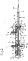
- a pipette 1 has a rod-shaped housing 2 in which a syringe 3 is held at the bottom. From a side wall of the housing 2 is above a straight line slot 4, an elevator lever 5 of the housing 2 before. From the same side wall of the housing is about two further slots 6, 7 before a control knob 8 a rack-pawl control. In addition, an LCD display 9 is embedded in the same side wall of the housing 2. From openings in the adjacent side wall are segments of a dial 10 out.
- the syringe 3 has a cylinder 11 and a piston 12 arranged displaceably therein.
- the cylinder 11 has at the bottom a conical portion 13 with a hole 14 for the passage of liquids and above a cylindrical portion 15 in which the piston 12 is displaceable.
- the cylinder 11 has a mounting portion 16 with a circumferential flange 17.
- From the piston 12 is upwardly a piston rod 18, which has a further mounting portion 19 with a plurality of circumferential beads (not shown).
- the syringe 3 is arranged with the flange 17 in a receptacle 20 at the lower end of the housing 2, which at the lower end of the housing 2 has an axially directed opening 21.1 for insertion and removal of the syringe 3.
- the syringe 3 presses with its upper side against a pressure-sensitive ring sensor 22, which scans projections on the upper edge of the flange 17.
- the flange 17 is held in this position by means of gripping levers 23 in the housing 2.
- the further attachment portion 19 of the piston 12 is arranged in a further receptacle 24 in a hollow cylindrical receiving body 25. This has for insertion of the attachment portion 19 on a further axially directed opening 21.2.
- the further attachment portion 19 is held by means of further gripping levers 26 which engage between the beads of the further attachment portion 19 or pinch it.
- the receiving body 25 is fixedly connected to a rack 27 which extends below the slot 4 in the longitudinal direction of the housing 2.
- An elevator lever holder 28 is fixed to the receiving body 25 and to a lower part of the rack 27.
- an elevator lever carrier 29 is present, which abuts with a sliding plate 30 at the bottom of the edges of the slot 4.
- the elevator lever carrier 29 has an upwardly projecting post 31, which passes through the slot 4. On the post outside the housing 2 of the elevator lever 5 is fixed.
- a metering lever 34 is pivotally mounted in a swivel bearing 32 in a bulge 33 of the slot 4 opposite side wall of the housing 2.
- the metering lever 34 has two from each other spaced legs 35, 36 which protrude on the opposite side wall of the housing 2 from the two slots 6, 7. There, the control knob 8 is fixed on the protruding ends of the legs 35, 36.
- a pawl 37 is pivotally mounted between the two legs 35, 36 of the metering lever 34.
- the pawl 37 is arranged with a ratchet tooth 38 above the toothing 39 of the rack 27.
- the metering lever 34 is moved by a spring device not shown in the position of Fig. 2 pressed. Contrary to the action of the spring device of the metering lever 34 by pressing the control knob 8 is pivoted downwards.
- the pawl 37 is pressed by means of a further spring means not shown to the teeth 39 of the rack 27.
- a sliding cover 40 is arranged between the pawl 37 and the rack 27, a sliding cover 40 is arranged.
- the cover 40 is displaceable by turning the laterally projecting out of the housing 2 dial 10 so that it covers the teeth 39 of the rack 27 more or less.
- a circuit board 41 is arranged with an electronics.
- an electrical power supply in the form of batteries or batteries 42.
- the dial 10 is associated with a further sensor 43 which detects the rotational position of the dial 10.
- the measured values determined by the ring sensor 22 and the further sensor 43 are forwarded to the electronics via cables.
- the code indicated on the flange 17 designates the size of the respective syringe 3.
- the electronics determine from the signals supplied by the ring sensor 22 Measuring signals, the respective syringe size and from the setting of the dial 10, the respective step size. From this, it calculates the set dosing volume and brings it to display 9 for display.
- the slots 6, 7 are covered on the inside by a diaphragm 44 connected to the metering lever 34.
- a flexible cover strip 45 is present.
- the stake strip 45 is made of polypropylene.
- Fig. 8 has the cover strip 45 at the ends of eyes 46, 47, according to Fig. 2 are fixed to pins 48, 49 projecting from the inside of the side wall of the housing 2, which has the slot 4.
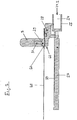
- the cover strip 45 extends through a channel 50 between the elevator lever holder 28 and the elevator lever carrier 29.
- the channel 50 is bounded on opposite sides by a side surface 51 with a radius of the elevator lever holder 28 and by a further side surface 52 with a corresponding radius of the elevator lever carrier 29.
- the two lateral boundaries of the channel 50 are formed by two strip-shaped side walls 53, 54 of the elevator lever carrier 29. These are connected to each other at a distance from the side surface 52 having the radius by a crossbar 55. Between the radius having further side surface 52 and the cross member 55, the elevator lever carrier has an opening 56.
- the elevator lever carrier 29 is preassembled with the cover strip 45 by the cover strip 45 is guided along the other side surface 52 and through the aperture 56 so that it extends on the top of the crossbar 55 between the two strip-shaped side walls 53, 54.
- the elevator lever carrier 29 is connectable to the elevator lever holder 28 by the projections 57, 58 are inserted into the pockets 59, 60 and elevator lever carrier 29 and elevator lever holder 28 are glued together or snapped together by means of suitable snap means.
- the cover strip 45 is then arranged in the channel 50 between side surface 51, further side surface 52 and side walls 53, 54.
- the cover strip 45 rests on a protruding rib 51.1 of the elevator lever holder 28 which extends in the longitudinal direction of the slot 4 (cf. 4 to 6 ).
- the elevator lever holder 28 and the elevator lever carrier 29 together form a connecting element 62 between the receiving body 25 and the elevator lever 5 (cf. Fig. 2 . 3 . 4 ).
- the elevator lever mount 28 has wings 63, 64 projecting from both sides.
- the wings 63, 64 have a cylindrical shape. They engage in grooves 65, 66 on two opposite side walls of the housing 2.
- the grooves 65, 66 are bounded on one side by an edge of a housing half and on the other side by a bar of a chassis in which parts of the drive mechanism of the pipette 1 are mounted.
- Fig. 2 is the cover strip 45 of the two pins 48, 49 to the eyes 46, 47 according to Fig. 8, 9 held clamped on the inside of the slot 4.
- Fig. 3 it is due to the radii of the side surfaces 51, 52 of the channel 50 on the level in which it is extended on both sides of the channel 50, bulged. As a result, a close contact of the cover strip 45 is achieved at the edges of the slot 4.
- the elevator lever 5 is moved out of the position of Fig. 1 and 2 pushed up.
- the absorbed amount of liquid can be dispensed in small steps by the control knob 8 is pressed repeatedly against the action of the spring device down.
- the further spring device presses the pawl 37 with the pawl tooth 38 against the cover 40 until the pawl tooth 38 reaches the lower end of the cover 40.
- the pawl 37 falls with the pawl tooth 38 in the toothing 39 of the rack 27 and takes the rack 27 during further pivoting of the metering lever 34 down with a piece.
- the displacement of the rack 27 depends on each pivoting of the metering lever 34 until reaching a lower stop of a set by means of the dial 10 position of the cover 40 from. After relieving the control knob 8 he is pushed by the spring device up and another dosing can be performed. This is possible until the residual amount of liquid left in the syringe 3 is smaller than the set metering amount. A Resthubsperre then ensures that the cover 40 is pivoted against the underside of the pawl 37, so that the ratchet tooth 38 can not occur in the teeth 39.
Landscapes
- Health & Medical Sciences (AREA)
- Clinical Laboratory Science (AREA)
- Chemical & Material Sciences (AREA)
- Chemical Kinetics & Catalysis (AREA)
- Sampling And Sample Adjustment (AREA)
- Devices For Use In Laboratory Experiments (AREA)
- Reciprocating Pumps (AREA)
- Feeding, Discharge, Calcimining, Fusing, And Gas-Generation Devices (AREA)
- Infusion, Injection, And Reservoir Apparatuses (AREA)
Claims (18)
- Pipette destinée à actionner une seringue avec• un logement en forme de tige (2),• une réception (20) avec une ouverture (21.1) à l'extrémité inférieure du logement (2) pour l'insertion d'une seringue (3) avec une section de fixation (16) sur le bord supérieur d'un cylindre (11),• un corps de réception (25) avec une réception supplémentaire (24) et une ouverture supplémentaire (21.2) à l'extrémité inférieure dans le logement (2) pour l'insertion d'une section de fixation supplémentaire (19) d'un piston (12) de la seringue (3),• des moyens pour le maintien amovible (23, 26) de la section de fixation (16) dans la réception (20) et de la section de fixation supplémentaire (19) dans la réception supplémentaire (24),• des moyens pour le déplacement (5, 8, 34, 37, 27) du corps de réception (25) au sein du logement (2) dans la direction longitudinale du logement (2),• qui présentent un levier d'armement (5) pouvant être actionné en dehors du logement (2) qui est connecté par le biais d'un élément de connexion (62) au corps de réception (25) qui pénètre à travers une fente en ligne droite (4) étendue dans la direction longitudinale du logement (2),caractérisée en ce• qu'une bande de recouvrement (45) recouvrant la fente est maintenue en dessous de la fente (4) dans le logement (2) à deux endroits (48, 49) dans le logement (2) écartés l'un de l'autre dans la direction longitudinale de la fente (4), et• que l'élément de connexion (62) présente un canal (50) à travers lequel la bande de recouvrement (45) s'étend.
- Pipette selon la revendication 1, dans laquelle le frottement entre les moyens pour le déplacement (5, 8, 34, 37, 27) du corps de réception (25) et/ou d'autres composants pouvant être déplacés dans le logement (2) qui sont connectés de manière fixe aux moyens pour le déplacement et des composants disposés de manière fixe dans le logement est mesuré de sorte que le levier d'armement (5) ne se déplace pas automatiquement le long de la fente (4) en cas d'orientation verticale de la pipette.
- Pipette selon la revendication 2, dans laquelle le frottement entre l'élément de connexion (62) et la bande de recouvrement (45) est mesuré de sorte que le levier d'armement (5) ne se déplace pas automatiquement le long de la fente (4) en cas d'orientation verticale de la pipette ou est mesuré en conséquence avec le frottement entre une autre paire de composants pouvant être déplacés dans le logement (2) et disposés de manière fixe dans le logement (2).
- Pipette selon une des revendications 1 à 3, caractérisée en ce que la bande de recouvrement (45) est flexible.
- Pipette selon la revendication 4, caractérisée en ce que le canal (50) dans l'élément de connexion (62) a une allure courbée en forme de U plate dans la direction longitudinale de la bande de recouvrement (45) de sorte que la bande de recouvrement (45) est déviée dans le canal (50) d'un plan dans lequel elle s'étend à côté de l'élément de connexion (62).
- Pipette selon une des revendications 1 à 5, caractérisée en ce que le canal (50) dans l'élément de connexion (62) sort avec ses embouchures de manière courbée dans le plan à travers les sections déviées de la bande de recouvrement (45).
- Pipette selon une des revendications 1 à 6, caractérisée en ce que le corps de réception (25) est connecté de manière fixe à au moins un élément d'appui (63, 64) qui s'appuie sur une voie d'appui (65, 66) dans le logement (2) qui est orientée parallèlement au plan à travers les sections de la bande de recouvrement (45) en dehors de l'élément de connexion (62).
- Pipette selon la revendication 7, caractérisée en ce que les éléments d'appui (63, 64) sont des ailes qui font saillie sur différents côtés du corps de réception (25) dans un plan qui est parallèle au plan dans lequel la bande de recouvrement (45) est disposée à côté de l'élément de connexion (62) et qui s'engrènent dans des rainures parallèles (65, 66) sur le côté interne de parois opposées l'une à l'autre du logement (2).
- Pipette selon une des revendications 1 à 8, caractérisée en ce que l'élément de connexion (62) présente un coulisseau s'engrenant dans la fente (4).
- Pipette selon une des revendications 1 à 9, caractérisée en ce que l'élément de connexion (62) présente une attache de levier d'armement (28) connectée de manière fixe au corps de réception (25), disposée dans le logement (2) et un support de levier d'armement (29) pénétrant à travers la fente et connecté au levier d'armement (5), dans laquelle le canal (50) est réalisé entre l'attache de levier d'armement (28) et le support de levier d'armement (29).
- Pipette selon la revendication 10, caractérisée en ce qu'une paroi du canal (50) est une face latérale (51) de l'attache de levier d'armement (28) et une paroi opposée du canal est une autre face latérale (52) du support de levier d'armement (29).
- Pipette selon la revendication 11, caractérisée en ce que l'attache de levier d'armement (28) et le support de levier d'armement (29) sont des composants assemblés.
- Pipette selon la revendication 9 en combinaison avec une des revendications 10 à 12, caractérisée en ce que le support de levier d'armement (29) présente le coulisseau.
- Pipette selon une des revendications 1 à 13, caractérisée en ce que la bande de recouvrement (45) est maintenue à deux endroits (48, 49) écartés l'un de l'autre aux deux extrémités et/ou en dehors des deux extrémités de la fente (4).
- Pipette selon une des revendications 1 à 14, caractérisée en ce que la bande de recouvrement (45) est fixée au logement (2) aux et/ou en dehors des deux extrémités de la fente (4) d'une ou de plusieurs des manières suivantes : conjugaison de formes, liaison de matière ou connexion par friction.
- Pipette selon la revendication 15, caractérisée en ce que la bande de recouvrement est fixée à des yeux (46, 47) ou oeillets sur des chevilles (48, 49) faisant saillie du côté interne du logement (2).
- Pipette selon une des revendications 1 à 16, caractérisée en ce que la bande de recouvrement (45) est tendue de manière élastique dans la direction longitudinale et/ou au moyen d'un ressort dans la direction longitudinale.
- Pipette selon une des revendications 1 à 17, caractérisée en ce que le logement (2) et la bande de recouvrement (45) sont fabriqués en le même plastique ou en plastiques différents.
Priority Applications (4)
| Application Number | Priority Date | Filing Date | Title |
|---|---|---|---|
| EP12002848.5A EP2656915B1 (fr) | 2012-04-23 | 2012-04-23 | Pipette destinée à actionner une seringue |
| PL12002848T PL2656915T3 (pl) | 2012-04-23 | 2012-04-23 | Pipeta do uruchamiania strzykawki |
| JP2013089447A JP6042764B2 (ja) | 2012-04-23 | 2013-04-22 | シリンジ操作用のピペット |
| CN201310142061.7A CN103372472B (zh) | 2012-04-23 | 2013-04-23 | 用于操纵注射器的移液器 |
Applications Claiming Priority (1)
| Application Number | Priority Date | Filing Date | Title |
|---|---|---|---|
| EP12002848.5A EP2656915B1 (fr) | 2012-04-23 | 2012-04-23 | Pipette destinée à actionner une seringue |
Publications (2)
| Publication Number | Publication Date |
|---|---|
| EP2656915A1 EP2656915A1 (fr) | 2013-10-30 |
| EP2656915B1 true EP2656915B1 (fr) | 2018-10-31 |
Family
ID=46045701
Family Applications (1)
| Application Number | Title | Priority Date | Filing Date |
|---|---|---|---|
| EP12002848.5A Active EP2656915B1 (fr) | 2012-04-23 | 2012-04-23 | Pipette destinée à actionner une seringue |
Country Status (4)
| Country | Link |
|---|---|
| EP (1) | EP2656915B1 (fr) |
| JP (1) | JP6042764B2 (fr) |
| CN (1) | CN103372472B (fr) |
| PL (1) | PL2656915T3 (fr) |
Families Citing this family (9)
| Publication number | Priority date | Publication date | Assignee | Title |
|---|---|---|---|---|
| WO2015174275A1 (fr) | 2014-05-12 | 2015-11-19 | 株式会社北里サイエンス | Dispositif de support de micropipette montée sur une lame et procédé d'injection de sperme dans du cytoplasme ovulaire |
| DE102014109345A1 (de) | 2014-07-04 | 2016-01-07 | Eppendorf Ag | Pipette zum Betätigen einer Spritze |
| CN106215991B (zh) * | 2016-08-29 | 2018-12-11 | 西北工业大学 | 一种用于液相萃取时液相分离的大容量移液器组合 |
| DE102016121813A1 (de) * | 2016-11-14 | 2018-05-17 | Ika-Werke Gmbh & Co. Kg | Pipette und Verfahren zum Einstellen eines zu pipettierenden Volumens einer Pipette |
| EP3335795B1 (fr) | 2016-12-16 | 2019-03-27 | Eppendorf AG | Procédé de dosage de liquide au moyen d'une pipette et d'une seringue et pipette destinée à actionner une seringue pour le dosage de liquides |
| PL3680016T3 (pl) * | 2019-01-08 | 2022-04-04 | Eppendorf Ag | Pipeta do używania z końcówką |
| CN111701630B (zh) * | 2020-06-01 | 2025-01-24 | 大龙兴创实验仪器(北京)股份公司 | 一种移液器 |
| EP3932557B1 (fr) * | 2020-07-02 | 2023-11-15 | Eppendorf SE | Tête de pipetage à canaux multiples |
| PL4279182T3 (pl) | 2022-05-19 | 2025-04-28 | Eppendorf Se | Pipeta do użytku z końcówką pipety |
Family Cites Families (14)
| Publication number | Priority date | Publication date | Assignee | Title |
|---|---|---|---|---|
| DE2926691C2 (de) | 1979-07-02 | 1983-05-26 | Eppendorf Gerätebau Netheler + Hinz GmbH, 2000 Hamburg | Repetierpipette |
| DE3100736A1 (de) | 1981-01-13 | 1982-08-26 | Ruhrchemie Ag, 4200 Oberhausen | Verfahren zur herstellung von traegerkatalysatoren fuer die polymerisation von (alpha)-olefinen |
| DE3204178C2 (de) * | 1982-02-06 | 1986-03-20 | Eppendorf Gerätebau Netheler + Hinz GmbH, 2000 Hamburg | Pipettiervorrichtung |
| DE3211271A1 (de) | 1982-03-26 | 1983-09-29 | Siemens AG, 1000 Berlin und 8000 München | Schieberregler |
| DE4341229C2 (de) | 1993-12-03 | 1995-09-07 | Eppendorf Geraetebau Netheler | Pipettensystem |
| DE4342178C2 (de) | 1993-12-10 | 1995-09-28 | Eppendorf Geraetebau Netheler | Pipettensystem |
| DE4414760C1 (de) * | 1994-04-27 | 1995-08-24 | Eppendorf Geraetebau Netheler | Repetierpipette |
| DE4437716C2 (de) | 1994-10-21 | 1996-10-17 | Eppendorf Geraetebau Netheler | Repetierpipette |
| DE19541628C2 (de) | 1995-11-08 | 2001-05-17 | Hellige Gmbh | Schiebesteller |
| DE10237770B4 (de) * | 2002-08-17 | 2006-11-09 | Eppendorf Ag | Pipettiervorrichtung |
| DE102005023203B4 (de) | 2005-05-20 | 2009-06-04 | Eppendorf Ag | Pipette |
| DE102007042115B4 (de) * | 2007-09-05 | 2010-12-02 | Eppendorf Ag | Pipette |
| DE102009016590A1 (de) * | 2009-03-31 | 2010-10-07 | Eppendorf Ag | Dosiervorrichtung |
| DE202010009747U1 (de) * | 2010-07-01 | 2010-11-18 | Brand Gmbh + Co Kg | Pipette für ein Pipettensystem mit Pipette und Spritze |
-
2012
- 2012-04-23 PL PL12002848T patent/PL2656915T3/pl unknown
- 2012-04-23 EP EP12002848.5A patent/EP2656915B1/fr active Active
-
2013
- 2013-04-22 JP JP2013089447A patent/JP6042764B2/ja active Active
- 2013-04-23 CN CN201310142061.7A patent/CN103372472B/zh active Active
Non-Patent Citations (1)
| Title |
|---|
| None * |
Also Published As
| Publication number | Publication date |
|---|---|
| JP2013228389A (ja) | 2013-11-07 |
| PL2656915T3 (pl) | 2019-04-30 |
| EP2656915A1 (fr) | 2013-10-30 |
| JP6042764B2 (ja) | 2016-12-14 |
| CN103372472A (zh) | 2013-10-30 |
| CN103372472B (zh) | 2016-11-09 |
Similar Documents
| Publication | Publication Date | Title |
|---|---|---|
| EP2656915B1 (fr) | Pipette destinée à actionner une seringue | |
| EP2591919B1 (fr) | Tampon | |
| EP0611544B1 (fr) | Buse en une pièce pour aspirateur | |
| DE3638722C2 (fr) | ||
| EP3164214B1 (fr) | Pipette servant à faire fonctionner une seringue | |
| EP0575790B1 (fr) | Dispositif d'application d'un film de matière adhésive sur un support | |
| EP3680016B1 (fr) | Pipette destinée à une utilisation avec une pointe de pipette | |
| EP2664426B1 (fr) | Protection de chaîne et système de scie à chaîne | |
| DE102012011938B4 (de) | Pipette zum Betätigen einer Spritze | |
| DE19635587A1 (de) | Handgerät zum Übertragen eines Filmes aus z. B.klebendem, deckendem oder farbigem Material von einem auf einer Vorratsspule aufgewickelten Trägerband auf ein Substrat | |
| EP0865242A1 (fr) | Machine manuelle pour remplir des tubes de cigarettes, notamment des tubes de cigarettes-filtres, avec une chambre de compactage du tabac a longueur variable | |
| DE29502642U1 (de) | Handgerät zum Übertragen eines Films von einem Trägerband auf ein Substrat | |
| EP3680017A1 (fr) | Pipette destinée à une utilisation avec une pointe de pipette | |
| DE102005017565B4 (de) | Haltevorrichtung | |
| EP1596689A1 (fr) | Barre de poignee destinee a un tiroir, en particulier a un tiroir de dispositifs de stockage et d'exploitation | |
| EP0688529A1 (fr) | Buse d'aspiration pour aspirateurs de poussière | |
| DE3906984A1 (de) | Vorratsbehaelter fuer gestapelte blaetter | |
| EP2783753A1 (fr) | Distributeur destiné à actionner une seringue | |
| EP0010260A2 (fr) | Serre-joints | |
| DE102011114688A1 (de) | Handdosiervorrichtung | |
| DE9401206U1 (de) | Deckel für einen Behälter | |
| EP4279182B1 (fr) | Pipette pour l'utilisation avec une pointe de pipette | |
| EP0839493B1 (fr) | Aspirateur comportant une chambre pour recevoir un sac à poussières | |
| EP3888791A1 (fr) | Point de pipette | |
| DE3707794C2 (de) | Stützelement mit horizontaler Kraftaufnahme für seitlich verschiebbare Abstützung eines Körpers auf einem anderen |
Legal Events
| Date | Code | Title | Description |
|---|---|---|---|
| PUAI | Public reference made under article 153(3) epc to a published international application that has entered the european phase |
Free format text: ORIGINAL CODE: 0009012 |
|
| AK | Designated contracting states |
Kind code of ref document: A1 Designated state(s): AL AT BE BG CH CY CZ DE DK EE ES FI FR GB GR HR HU IE IS IT LI LT LU LV MC MK MT NL NO PL PT RO RS SE SI SK SM TR |
|
| AX | Request for extension of the european patent |
Extension state: BA ME |
|
| 17P | Request for examination filed |
Effective date: 20140331 |
|
| RBV | Designated contracting states (corrected) |
Designated state(s): AL AT BE BG CH CY CZ DE DK EE ES FI FR GB GR HR HU IE IS IT LI LT LU LV MC MK MT NL NO PL PT RO RS SE SI SK SM TR |
|
| GRAP | Despatch of communication of intention to grant a patent |
Free format text: ORIGINAL CODE: EPIDOSNIGR1 |
|
| STAA | Information on the status of an ep patent application or granted ep patent |
Free format text: STATUS: GRANT OF PATENT IS INTENDED |
|
| INTG | Intention to grant announced |
Effective date: 20180524 |
|
| GRAS | Grant fee paid |
Free format text: ORIGINAL CODE: EPIDOSNIGR3 |
|
| GRAA | (expected) grant |
Free format text: ORIGINAL CODE: 0009210 |
|
| STAA | Information on the status of an ep patent application or granted ep patent |
Free format text: STATUS: THE PATENT HAS BEEN GRANTED |
|
| AK | Designated contracting states |
Kind code of ref document: B1 Designated state(s): AL AT BE BG CH CY CZ DE DK EE ES FI FR GB GR HR HU IE IS IT LI LT LU LV MC MK MT NL NO PL PT RO RS SE SI SK SM TR |
|
| REG | Reference to a national code |
Ref country code: CH Ref legal event code: EP Ref country code: GB Ref legal event code: FG4D Free format text: NOT ENGLISH |
|
| REG | Reference to a national code |
Ref country code: AT Ref legal event code: REF Ref document number: 1058739 Country of ref document: AT Kind code of ref document: T Effective date: 20181115 |
|
| REG | Reference to a national code |
Ref country code: DE Ref legal event code: R096 Ref document number: 502012013699 Country of ref document: DE |
|
| REG | Reference to a national code |
Ref country code: IE Ref legal event code: FG4D Free format text: LANGUAGE OF EP DOCUMENT: GERMAN |
|
| REG | Reference to a national code |
Ref country code: CH Ref legal event code: NV Representative=s name: ISLER AND PEDRAZZINI AG, CH |
|
| REG | Reference to a national code |
Ref country code: NL Ref legal event code: MP Effective date: 20181031 |
|
| REG | Reference to a national code |
Ref country code: LT Ref legal event code: MG4D |
|
| PG25 | Lapsed in a contracting state [announced via postgrant information from national office to epo] |
Ref country code: BG Free format text: LAPSE BECAUSE OF FAILURE TO SUBMIT A TRANSLATION OF THE DESCRIPTION OR TO PAY THE FEE WITHIN THE PRESCRIBED TIME-LIMIT Effective date: 20190131 Ref country code: FI Free format text: LAPSE BECAUSE OF FAILURE TO SUBMIT A TRANSLATION OF THE DESCRIPTION OR TO PAY THE FEE WITHIN THE PRESCRIBED TIME-LIMIT Effective date: 20181031 Ref country code: LT Free format text: LAPSE BECAUSE OF FAILURE TO SUBMIT A TRANSLATION OF THE DESCRIPTION OR TO PAY THE FEE WITHIN THE PRESCRIBED TIME-LIMIT Effective date: 20181031 Ref country code: HR Free format text: LAPSE BECAUSE OF FAILURE TO SUBMIT A TRANSLATION OF THE DESCRIPTION OR TO PAY THE FEE WITHIN THE PRESCRIBED TIME-LIMIT Effective date: 20181031 Ref country code: LV Free format text: LAPSE BECAUSE OF FAILURE TO SUBMIT A TRANSLATION OF THE DESCRIPTION OR TO PAY THE FEE WITHIN THE PRESCRIBED TIME-LIMIT Effective date: 20181031 Ref country code: ES Free format text: LAPSE BECAUSE OF FAILURE TO SUBMIT A TRANSLATION OF THE DESCRIPTION OR TO PAY THE FEE WITHIN THE PRESCRIBED TIME-LIMIT Effective date: 20181031 Ref country code: NO Free format text: LAPSE BECAUSE OF FAILURE TO SUBMIT A TRANSLATION OF THE DESCRIPTION OR TO PAY THE FEE WITHIN THE PRESCRIBED TIME-LIMIT Effective date: 20190131 Ref country code: IS Free format text: LAPSE BECAUSE OF FAILURE TO SUBMIT A TRANSLATION OF THE DESCRIPTION OR TO PAY THE FEE WITHIN THE PRESCRIBED TIME-LIMIT Effective date: 20190228 |
|
| PG25 | Lapsed in a contracting state [announced via postgrant information from national office to epo] |
Ref country code: PT Free format text: LAPSE BECAUSE OF FAILURE TO SUBMIT A TRANSLATION OF THE DESCRIPTION OR TO PAY THE FEE WITHIN THE PRESCRIBED TIME-LIMIT Effective date: 20190301 Ref country code: GR Free format text: LAPSE BECAUSE OF FAILURE TO SUBMIT A TRANSLATION OF THE DESCRIPTION OR TO PAY THE FEE WITHIN THE PRESCRIBED TIME-LIMIT Effective date: 20190201 Ref country code: NL Free format text: LAPSE BECAUSE OF FAILURE TO SUBMIT A TRANSLATION OF THE DESCRIPTION OR TO PAY THE FEE WITHIN THE PRESCRIBED TIME-LIMIT Effective date: 20181031 Ref country code: RS Free format text: LAPSE BECAUSE OF FAILURE TO SUBMIT A TRANSLATION OF THE DESCRIPTION OR TO PAY THE FEE WITHIN THE PRESCRIBED TIME-LIMIT Effective date: 20181031 Ref country code: SE Free format text: LAPSE BECAUSE OF FAILURE TO SUBMIT A TRANSLATION OF THE DESCRIPTION OR TO PAY THE FEE WITHIN THE PRESCRIBED TIME-LIMIT Effective date: 20181031 Ref country code: AL Free format text: LAPSE BECAUSE OF FAILURE TO SUBMIT A TRANSLATION OF THE DESCRIPTION OR TO PAY THE FEE WITHIN THE PRESCRIBED TIME-LIMIT Effective date: 20181031 |
|
| PG25 | Lapsed in a contracting state [announced via postgrant information from national office to epo] |
Ref country code: CZ Free format text: LAPSE BECAUSE OF FAILURE TO SUBMIT A TRANSLATION OF THE DESCRIPTION OR TO PAY THE FEE WITHIN THE PRESCRIBED TIME-LIMIT Effective date: 20181031 Ref country code: DK Free format text: LAPSE BECAUSE OF FAILURE TO SUBMIT A TRANSLATION OF THE DESCRIPTION OR TO PAY THE FEE WITHIN THE PRESCRIBED TIME-LIMIT Effective date: 20181031 Ref country code: IT Free format text: LAPSE BECAUSE OF FAILURE TO SUBMIT A TRANSLATION OF THE DESCRIPTION OR TO PAY THE FEE WITHIN THE PRESCRIBED TIME-LIMIT Effective date: 20181031 |
|
| REG | Reference to a national code |
Ref country code: DE Ref legal event code: R097 Ref document number: 502012013699 Country of ref document: DE |
|
| PG25 | Lapsed in a contracting state [announced via postgrant information from national office to epo] |
Ref country code: SK Free format text: LAPSE BECAUSE OF FAILURE TO SUBMIT A TRANSLATION OF THE DESCRIPTION OR TO PAY THE FEE WITHIN THE PRESCRIBED TIME-LIMIT Effective date: 20181031 Ref country code: RO Free format text: LAPSE BECAUSE OF FAILURE TO SUBMIT A TRANSLATION OF THE DESCRIPTION OR TO PAY THE FEE WITHIN THE PRESCRIBED TIME-LIMIT Effective date: 20181031 Ref country code: EE Free format text: LAPSE BECAUSE OF FAILURE TO SUBMIT A TRANSLATION OF THE DESCRIPTION OR TO PAY THE FEE WITHIN THE PRESCRIBED TIME-LIMIT Effective date: 20181031 Ref country code: SM Free format text: LAPSE BECAUSE OF FAILURE TO SUBMIT A TRANSLATION OF THE DESCRIPTION OR TO PAY THE FEE WITHIN THE PRESCRIBED TIME-LIMIT Effective date: 20181031 |
|
| PLBE | No opposition filed within time limit |
Free format text: ORIGINAL CODE: 0009261 |
|
| STAA | Information on the status of an ep patent application or granted ep patent |
Free format text: STATUS: NO OPPOSITION FILED WITHIN TIME LIMIT |
|
| 26N | No opposition filed |
Effective date: 20190801 |
|
| PG25 | Lapsed in a contracting state [announced via postgrant information from national office to epo] |
Ref country code: SI Free format text: LAPSE BECAUSE OF FAILURE TO SUBMIT A TRANSLATION OF THE DESCRIPTION OR TO PAY THE FEE WITHIN THE PRESCRIBED TIME-LIMIT Effective date: 20181031 |
|
| REG | Reference to a national code |
Ref country code: BE Ref legal event code: MM Effective date: 20190430 |
|
| PG25 | Lapsed in a contracting state [announced via postgrant information from national office to epo] |
Ref country code: MC Free format text: LAPSE BECAUSE OF FAILURE TO SUBMIT A TRANSLATION OF THE DESCRIPTION OR TO PAY THE FEE WITHIN THE PRESCRIBED TIME-LIMIT Effective date: 20181031 Ref country code: LU Free format text: LAPSE BECAUSE OF NON-PAYMENT OF DUE FEES Effective date: 20190423 |
|
| PG25 | Lapsed in a contracting state [announced via postgrant information from national office to epo] |
Ref country code: BE Free format text: LAPSE BECAUSE OF NON-PAYMENT OF DUE FEES Effective date: 20190430 |
|
| PG25 | Lapsed in a contracting state [announced via postgrant information from national office to epo] |
Ref country code: TR Free format text: LAPSE BECAUSE OF FAILURE TO SUBMIT A TRANSLATION OF THE DESCRIPTION OR TO PAY THE FEE WITHIN THE PRESCRIBED TIME-LIMIT Effective date: 20181031 |
|
| PG25 | Lapsed in a contracting state [announced via postgrant information from national office to epo] |
Ref country code: IE Free format text: LAPSE BECAUSE OF NON-PAYMENT OF DUE FEES Effective date: 20190423 |
|
| REG | Reference to a national code |
Ref country code: AT Ref legal event code: MM01 Ref document number: 1058739 Country of ref document: AT Kind code of ref document: T Effective date: 20190423 |
|
| PG25 | Lapsed in a contracting state [announced via postgrant information from national office to epo] |
Ref country code: AT Free format text: LAPSE BECAUSE OF NON-PAYMENT OF DUE FEES Effective date: 20190423 |
|
| PG25 | Lapsed in a contracting state [announced via postgrant information from national office to epo] |
Ref country code: CY Free format text: LAPSE BECAUSE OF FAILURE TO SUBMIT A TRANSLATION OF THE DESCRIPTION OR TO PAY THE FEE WITHIN THE PRESCRIBED TIME-LIMIT Effective date: 20181031 |
|
| PG25 | Lapsed in a contracting state [announced via postgrant information from national office to epo] |
Ref country code: MT Free format text: LAPSE BECAUSE OF FAILURE TO SUBMIT A TRANSLATION OF THE DESCRIPTION OR TO PAY THE FEE WITHIN THE PRESCRIBED TIME-LIMIT Effective date: 20181031 Ref country code: HU Free format text: LAPSE BECAUSE OF FAILURE TO SUBMIT A TRANSLATION OF THE DESCRIPTION OR TO PAY THE FEE WITHIN THE PRESCRIBED TIME-LIMIT; INVALID AB INITIO Effective date: 20120423 |
|
| REG | Reference to a national code |
Ref country code: FR Ref legal event code: PLFP Year of fee payment: 11 |
|
| PG25 | Lapsed in a contracting state [announced via postgrant information from national office to epo] |
Ref country code: MK Free format text: LAPSE BECAUSE OF FAILURE TO SUBMIT A TRANSLATION OF THE DESCRIPTION OR TO PAY THE FEE WITHIN THE PRESCRIBED TIME-LIMIT Effective date: 20181031 |
|
| REG | Reference to a national code |
Ref country code: DE Ref legal event code: R081 Ref document number: 502012013699 Country of ref document: DE Owner name: EPPENDORF SE, DE Free format text: FORMER OWNER: EPPENDORF AG, 22339 HAMBURG, DE |
|
| P01 | Opt-out of the competence of the unified patent court (upc) registered |
Effective date: 20230527 |
|
| PGFP | Annual fee paid to national office [announced via postgrant information from national office to epo] |
Ref country code: PL Payment date: 20250411 Year of fee payment: 14 Ref country code: DE Payment date: 20250422 Year of fee payment: 14 |
|
| PGFP | Annual fee paid to national office [announced via postgrant information from national office to epo] |
Ref country code: GB Payment date: 20250423 Year of fee payment: 14 |
|
| PGFP | Annual fee paid to national office [announced via postgrant information from national office to epo] |
Ref country code: FR Payment date: 20250425 Year of fee payment: 14 |
|
| PGFP | Annual fee paid to national office [announced via postgrant information from national office to epo] |
Ref country code: CH Payment date: 20250501 Year of fee payment: 14 |