EP2656916B1 - Procédé de dosage de liquide au moyen d'une pipette et d'une seringue ainsi que la pipette destinée à actionner une seringue pour le dosage de liquides - Google Patents
Procédé de dosage de liquide au moyen d'une pipette et d'une seringue ainsi que la pipette destinée à actionner une seringue pour le dosage de liquides Download PDFInfo
- Publication number
- EP2656916B1 EP2656916B1 EP12002849.3A EP12002849A EP2656916B1 EP 2656916 B1 EP2656916 B1 EP 2656916B1 EP 12002849 A EP12002849 A EP 12002849A EP 2656916 B1 EP2656916 B1 EP 2656916B1
- Authority
- EP
- European Patent Office
- Prior art keywords
- syringe
- dosing
- pipette
- steps
- liquid
- Prior art date
- Legal status (The legal status is an assumption and is not a legal conclusion. Google has not performed a legal analysis and makes no representation as to the accuracy of the status listed.)
- Active
Links
Images








Classifications
-
- B—PERFORMING OPERATIONS; TRANSPORTING
- B01—PHYSICAL OR CHEMICAL PROCESSES OR APPARATUS IN GENERAL
- B01L—CHEMICAL OR PHYSICAL LABORATORY APPARATUS FOR GENERAL USE
- B01L3/00—Containers or dishes for laboratory use, e.g. laboratory glassware; Droppers
- B01L3/02—Burettes; Pipettes
- B01L3/021—Pipettes, i.e. with only one conduit for withdrawing and redistributing liquids
- B01L3/0217—Pipettes, i.e. with only one conduit for withdrawing and redistributing liquids of the plunger pump type
- B01L3/0234—Repeating pipettes, i.e. for dispensing multiple doses from a single charge
-
- B—PERFORMING OPERATIONS; TRANSPORTING
- B01—PHYSICAL OR CHEMICAL PROCESSES OR APPARATUS IN GENERAL
- B01L—CHEMICAL OR PHYSICAL LABORATORY APPARATUS FOR GENERAL USE
- B01L3/00—Containers or dishes for laboratory use, e.g. laboratory glassware; Droppers
- B01L3/02—Burettes; Pipettes
- B01L3/0275—Interchangeable or disposable dispensing tips
- B01L3/0279—Interchangeable or disposable dispensing tips co-operating with positive ejection means
-
- B—PERFORMING OPERATIONS; TRANSPORTING
- B01—PHYSICAL OR CHEMICAL PROCESSES OR APPARATUS IN GENERAL
- B01L—CHEMICAL OR PHYSICAL LABORATORY APPARATUS FOR GENERAL USE
- B01L2300/00—Additional constructional details
- B01L2300/02—Identification, exchange or storage of information
Definitions
- the invention relates to a method for dosing liquid by means of a pipette and a syringe and to a pipette for actuating a syringe for dosing liquid.
- the pipettes used here for actuating a syringe serve to dispense liquid received in the syringe in several steps. They are also referred to as dispensers or repeating pipettes. These pipettes have at the lower end of a rod-shaped housing a receptacle for a flange of a cylinder of the syringe and in the housing a displaceable receiving body with a piston receptacle for the upper end portion of a piston rod of a piston of the syringe.
- the syringe can be used with the flange and the end portion of the piston rod through axially directed openings of the receptacles.
- the flange and the end portion are held in the receptacles by means for detachable holding, which are designed, for example, as spring-loaded gripping levers.
- the pipette comprises means for displacing the receiving body, which allow a partial withdrawal of the piston from the cylinder for the suction of liquid into the syringe and a stepwise depression of the piston into the cylinder for the stepwise discharge of liquid.
- the DE 2926691 C2 and the US 4406170 A describe means for displacing the receiving body in the housing. These include an elevator lever connected to the receiving body and projecting out of the housing through a straight-line slot for drawing fluid into the syringe by displacing the receiving body away from the receptacle. In addition, they include a rack-pawl means for gradually advancing the piston by a reciprocating metering lever. At the metering lever is a pivoting pawl stored. The rack is connected to the receiving body and arranged in the pivoting range of the pawl. An adjustable sliding cover covers more or less the row of teeth on the rack in order to limit the engagement of the pawl in the rack when pivoting the metering lever.
- the rack is designed with a contour through which in the advanced position of the piston, the cover of the rack is displaced away, so that it prevents the pawl from engaging in the uncovered teeth of the rack. This prevents that a residual amount is discharged from the syringe, which is smaller than the dispensed in each dosing step dosage.
- the EP 0657216 B1 and US 5620661 A describe such a pipette with a sensor for sensing protrusions and depressions on the syringe flange and associated syringes.
- the sensor is used to determine the size of the syringe used.
- electronics determines the amount of fluid dispensed at each dispensing step. This is displayed on a display.
- the known manually operated repeating pipettes have the disadvantage that the user has to look up the maximum number of dosing steps that are possible with completely filled syringe with the set dosing volume after performing a reverse stroke without refilling the syringe in the manual or experimentally determined. Furthermore, the user must count the dosing steps performed if he wants to know the number of additional dosing steps that are still possible with the remaining liquid in the syringe. This is particularly troublesome and error prone with small dosing increments.
- the object of the invention is to provide a method for dosing liquid by means of a pipette and a syringe and a pipette for actuating a syringe for dosing liquid with more favorable application properties.
- the user is shown the maximum number of metering steps that are possible with completely filled syringe with the set metering volume after performing a reverse stroke without refilling the syringe. Furthermore, the user is shown the number of dosing steps performed and / or the number of dosing steps still possible without refilling the syringe with the set dosing increment.
- a residual amount of liquid remains that is less than the set metering volume.
- the user After the maximum number of dosing steps has been performed, the user either has the option of dislodging the used syringe from the pipette and starting the procedure again from the beginning after inserting a new syringe. Alternatively, the user may use the same syringe multiple times. If he repeatedly uses the syringe, the display device displays the total number of dosing steps performed by the same syringe. The user can thus perform the dosing easier and with reduced risk of error.
- the number of executed dosing steps is displayed instead of the display of the still possible number of dosing steps.
- the number of refilling of the syringe still possible dosing steps is displayed.
- the number of possible dosing steps is the difference between the possible maximum number of dosing steps and the number of executed dosing steps.
- the number of metering steps performed and the number of possible metering steps until the syringe is completely emptied are displayed.
- one of the two abovementioned numbers is displayed larger than the other one. For example, During dispensing, the sum of the executed number of dosing steps greater than the number of possible dosing steps displayed.
- the pipette detects a coding of the syringe connected to the pipette and indicates the metering volume on the basis of the set metering increment and the detected coding detected and displayed by the display device.
- This embodiment allows the use of different sized syringes, which always automatically the dosing volume is displayed, which is delivered at the set dosing increment with each syringe used.
- a display indicative of the picking up of liquid is indicated by means of the display device.
- the display is according to an embodiment an upward arrow or other obvious symbol. This facilitates the operation of the pipette.
- a flashing or otherwise indicative of the current process of receiving liquid into the syringe and performing a reverse stroke is displayed.
- the user is instructed to fill the syringe completely with liquid as far as possible and to perform the reversal stroke.
- operator errors and dosing errors can be avoided.
- the set metering volume and the number of metering steps have been indicated.
- the user can obtain information at any time about the set dosing volume and the number of doses taken.
- a display indicative of the dispensing of liquid is displayed.
- the display is according to one embodiment, a downward arrow or other obvious symbol. This facilitates the operation of the pipette.
- a display indicating the optional dispensing of residual liquid from the syringe and detaching the syringe from the pipette or taking up further liquid by means of the same syringe is displayed.
- the display comprises a downward and an upward arrow or other obvious symbols. This facilitates the operation of the pipette.
- an indication indicative of the setting of the pipette to a lower end position for receiving liquid is displayed when the pipette is not in the lower end position for picking up liquid located.
- the display is according to one embodiment, a downwardly directed arrow or other obvious symbol for the setting of the pipette in the lower end position. This facilitates the operation of the pipette.
- the newly set metering and the possible without refilling the pipette maximum number of additional metering with the newly set metering volume is displayed and the number of further dosing steps carried out is displayed with the newly set dosing volume by means of the display device.
- the user receives the information about the set dosing volume, the maximum possible number of further dosing steps and the number of further dosing steps performed.
- the maximum number of further dosing steps possible without refilling the syringe with the previously set dosing increment by means of the display device and the dosing steps carried out by means of the dosing step width set after the reset or the total dosing steps performed before and after the reset are counted and displayed by means of the display device.
- the control device determines the possible maximum number of metering steps, which is possible after complete filling of the syringe without refilling the syringe, on the basis of the detected metering step width and data present in the control device about the syringe used.
- the control device displays the metering volume determined from the metering step width and the determined maximum number of metering steps. When dosages take place, this is signaled to the control device by the means for detecting the execution of a dosing step.
- the control device counts the metering steps and displays the respectively performed number of metering steps by means of display device.
- the control device is such that the display of the number of dosing steps carried out takes place instead of the display of the number of dosing steps still possible without refilling the syringe.
- the control device is designed such that the display of the number of dosing steps still possible without refilling the syringe takes place in place of the display of the number of dosing steps carried out.
- the control device is such that the number of metering steps performed and at the same time the number of metering steps still possible without refilling the syringe is displayed.
- the pipette has a sensor for detecting a coding indicating the syringe volume on a syringe detachably connected to the pipette.
- the control device always determines the set metering volume based on the set metering step size and the determined syringe volume and displays it via the display device.
- the sensor is a ring sensor.
- the sensor for detecting a coding is according to a preferred embodiment at the same time the means for detecting a syringe detachably connected to the pipette.
- control device is designed such that, after carrying out the maximum number of metering steps and refilling the same syringe, the total number of metering steps performed with the syringe with the set metering increment is determined and / or the number of metering steps still possible without refilling the syringe is determined and indicated by the display device.
- the control device is designed so that it indicates a flashing or otherwise indicative of the current process of receiving liquid in the syringe and performing a reverse stroke when recording liquid until complete execution of a reverse stroke by means of the display.
- the pipette according to one embodiment comprises means for detecting a displacement of the receiving body in a lower end position for releasable connection with a syringe and means for detecting a displacement of the receiving body in an upper end position for the full filling of a syringe, said means for detecting are connected to the electronic control device. These means for detecting signal to the controller that a syringe has been completely filled.
- the execution of the reverse stroke can be signaled to the control device by the means for detecting the execution of a dosing step if the reverse stroke is controlled by the control knob.
- means for detecting a reverse stroke are provided, which detect the operation of a transfer member for the reverse stroke and are connected to the electronic control device.
- the transfer member for the reverse stroke is coupled to the receiving body, so that it at the end of the displacement of the receiving body in the upper end position for the complete Filling the syringe taken and taken in reverse stroke in the opposite direction and are the means for detecting the displacement of the receiving body in the upper end position at the same time the means for detecting the Umledgehubes.
- These means for detecting are formed according to an embodiment by a single microswitch, which is switched by the transfer member for the reverse stroke in reaching the position for the full filling of the syringe and after execution of the reverse stroke in different switching states.
- control device is designed such that it indicates, after complete execution of the reversal stroke by means of the display device indicative of the dispensing of liquid.
- the execution of the reverse stroke is signaled to the control device by the means for detecting the execution of a dosing step or by the means for detecting the execution of a reverse stroke.
- the control device is designed such that, after dispensing residual liquid from the syringe by means of the display device, it indicates an indication of the release of the syringe.
- the delivery of residual liquid from the syringe is signaled to the controller by the means for detecting the displacement of the receiving body to a lower end position for insertion of the syringe. In the lower end position, the receiving body is displaced as far as possible for receiving the syringe barrel.
- the control device then brings this information to the display when previously dosing has taken place. This can be signaled to the control device by the means for detecting the execution of a dosing step.
- control device is such that after the detachable connection of the pipette to the syringe and before the liquid is taken up into the syringe by means of the display device, a display indicative of the setting of the pipette into a lower end position for receiving liquid is displayed when the pipette is not in the initial position for picking up liquid. This will be the pipette signaled by the means for detecting the arrangement of the receiving body in the lower end position for the insertion of a syringe.
- control device is such that, after changing the dosing step size and subsequent resetting of the dosing step size to the previously set value, the maximum number of additional dosing steps with the dosing step width set by the display device without refilling the syringe is indicated by means of the display device and by means of the display again metering steps performed after the reset counts and displays by means of the display device or counts before and after the reset total metering steps and displays by means of the display device.
- the control device stores when changing the Dosier intimidweite the previously set value of the metering step and the number of metering steps performed.
- control device is designed so that it indicates in the case of performing dosing steps after incomplete fluid intake into the syringe by means of the display device indicative of the execution of a reverse stroke display until the reversal stroke is performed by one or more dosing steps on it the following dosing counts and indicates by means of the display.
- the incomplete fluid intake is signaled to the pipette in that the means for detecting dosing steps signal the execution of dosing steps, without the means for detecting a displacement of the receiving body in the upper end position signaling the displacement of the receiving body in the upper end position.
- the means for holding the attachment portion in the receptacle and the further attachment portion in the further receptacle are preferably formed as described in the above-mentioned prior art documents.
- the means for displacing the receiving body within the housing are preferably formed as described in the prior art documents mentioned above.
- the sensor for detecting a coding of a syringe and the coding of the syringe are preferably designed as described in the prior art documents mentioned above. In this regard, reference is made to the documents mentioned above DE 29 26 691 C2 . US 4,406,170A . DE 44 37 716 C2 . EP 0 679 439 B1 . US 5,591,408A . EP 056 229 B1 . US 5,620,660 A . EP 1 724 020 B1 . US 7,731,908 B2 . EP 0 657,216 B1 . US 5,620,661 A , the contents of which are hereby incorporated into the present application.
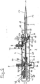
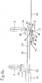
- the syringe 3 has a cylinder 11 and a piston 12 arranged displaceably therein.
- the cylinder 11 has at the bottom a conical portion 13 with a hole 14 for the passage of liquids and above a cylindrical portion 15 in which the piston 12 is displaceable.
- Above has the Cylinder 11 a mounting portion 16 with a circumferential flange 17.
- From the piston 12 is upwardly a piston rod 18 before, which has a further mounting portion 19 with a plurality of circumferential beads (not shown).
- the syringe 3 is arranged with the flange 17 in a receptacle 20 at the lower end of the housing 2, which at the lower end of the housing 2 has an axially directed opening 21.1 for insertion and removal of the syringe 3.
- the syringe 3 presses with its upper side against a pressure-sensitive ring sensor 22, which scans projections on the upper edge of the flange 17.
- the flange 17 is held in this position by means of gripping levers 23 in the housing 2.
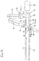
- the receiving body 25 is fixedly connected to a rack 27 which extends below the slot 4 in the longitudinal direction of the housing 2.
- An elevator lever holder 28 is fixed to the receiving body 25 and to a lower part of the rack 27.
- a sliding cover 40 is arranged between the pawl 37 and the rack 27, a sliding cover 40 is arranged.
- the cover 40 is displaceable by turning the laterally projecting out of the housing 2 dial 10 so that it covers the teeth 39 of the rack 27 more or less.
- a circuit board 41 is arranged with an electronics.
- an electrical power supply in the form of batteries or batteries 42.
- the dial 10 is associated with a further sensor 43 which detects the rotational position of the dial 10.
- the measured values determined by the ring sensor 22 and the further sensor 43 are forwarded to the electronics via cables.
- the slots 6, 7 are covered on the inside by a diaphragm 44 connected to the metering lever 34.
- the elevator lever holder 28 and the elevator lever carrier 29 together form a connecting element 62 between the receiving body 25 and the elevator lever 5 (cf. Fig. 2 . 3 . 4 ).
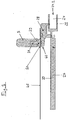
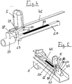
- Fig. 2 is the cover strip 45 of the two pins 48, 49 to the eyes 46, 47 according to Fig. 8, 9 held clamped on the inside of the slot 4.
- Fig. 3 it is due to the radii of the side surfaces 51, 52 of the channel 50 on the level in which it is extended on both sides of the channel 50, bulged. As a result, a close contact of the cover strip 45 is achieved at the edges of the slot 4.
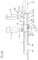
- Fig. 10 and 11 carries the circuit board 41 on the side facing away from the rack 27 side at its lower end designed as a microswitch upper limit switch 67 for detecting the upper end position of the receiving body 25.
- the upper limit switch 67 is a button with a respect to the circuit board 41 outwardly projecting lever 68th
- the transmission member 69 has above two control arms 73, 74, in the (zu Fig. 10 and 11 vertical) plane of the circuit board 41 are extended and engage around the lower end of the circuit board 41 on both sides.
- the transmission element 69 is displaceable such that the control arms 73, 74 with upper control arm ends 75, 76 in the displacement region of bevelled stop edges 77, 78 on the legs 35, reach 36 (cf. Fig. 10 to 13 ).
- the ring sensor 22 scans the coding on the flange 17 of the syringe 3.
- the control device 87 determines from the signals supplied by the ring sensor 22 that a syringe 3 is inserted and switches the display 9 on. Based on the signals supplied by the ring sensor 22 and the signals supplied by the sensor 43, the control device 87 determines the set metering volume and displays it on the display 9. Optionally, the user changes the setting of the metering volume by means of the dial 10 and the changed metering volume is displayed by the display 9.
- the elevator lever 5 is moved out of the position of Fig. 1 . 2 and 13 pushed up.
- the upper stop 83 operates according to Fig. 13 the sensing lever 82 of the lower limit switch 81.
- the upper stop 83 releases the lower limit switch 81, as shown in FIG Fig. 12 will be shown.
- this signals the lower limit switch 81 of the controller 87, this controls a flashing of the display on the display.
- a reverse stroke must be carried out. This is done by pressing the control knob 8. Here hit the stop edges 74, 78 on the control arms 73, 74 and move the transmission member 69 down. The transmission member 69 takes over the lower stop 72 with the rack 27. This reverse stroke removes the lots from the system.
- the switching arm 79 is released from the sensing lever 68 of the upper limit switch 67, whereby the controller 87 is signaled that the reversal stroke has been executed.
- the pin 85 hits the dosing step sensor 84 and actuates it (cf. Fig. 14 ). This signals the control device 87 to carry out a dosing step.
- the control device 87 adds the dosing steps carried out and displays the respective number of dosing steps carried out on the display 9.
- the control device 87 then indicates on the display 9 that the maximum number of metering steps has taken place. It also indicates by indicating an upward and downward arrow on the display 9 the indication that either liquid can be sucked into the syringe 3 again or empties the residual liquid from the syringe 3 and the syringe 3 separated from the pipette 1 can be. If additional liquid is absorbed into the same syringe 3, the sequence is as described above, wherein the controller 87 determines the sum of the dosing performed with the same dosing and displays on the display 9.
- a residual liquid in the syringe 3 can be discharged by displacing the elevator lever 5 down.
- the lower limit switch 81 is actuated.
- the control device 87 displays a downward arrow on the display 9 as an indication that the syringe 3 can be separated from the pipette 1.
- the user actuates the handle lever 23, 26th
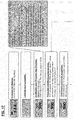
- Fig. 17 The procedure described above is in Fig. 17 illustrated.
- the respective display is indicated in the display and with explanations.
- the example shows a set dosing volume of 500 ml.
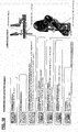
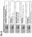
- Fig. 18 The expiration of Fig. 18 is different from the expiration of Fig. 17 in that the elevator lever 5 is not in the lower end position when releasably connecting the pipette 1 to the syringe 3.
- This can be detected by the control device 87 that the ring sensor 22 reports the onset of a syringe 3 and the lower limit switch 81 reports that the receiving body 25 is not in the lowest end position.
- the display on the display device 9 by a downward arrow to indicate to shift the elevator lever 5 down. Only when this is done, the set dosing volume, the maximum number of metering steps and the upward arrow is displayed as an indication of the filling of the syringe 3.
- the further procedure corresponds to that of Fig. 17 ,
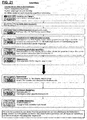
- Fig. 20 The expiration of Fig. 20 is different from the expiration of Fig. 19 in that, after the change in the dosing volume, the dosing volume is reset to the original value.
- the metering volume is changed after a metering step of 500 ml to a metering volume of 250 ml. After a metering step with a metering volume of 250 ml, the metering volume is reset to the original metering volume of 500 ml. Thereafter, the with the original metering volume and the displayed in the syringe amount of liquid possible maximum number of additional dosing steps.
- the dosing steps that have taken place after returning to the original dosing quantity to the original value with this dosing quantity are counted and displayed.
- the dosing steps taken in total before and after the reset are counted and displayed when the dosing quantity is reset to the originally set value during dispensing.
- Fig. 21 The expiration of Fig. 21 is different from the expiration of Fig. 17 in that the syringe 3 is only partially filled.
- This is determined by the controller 87 based on the signals of the lower limit switch 81 and the upper limit switch 67. Namely, when the lower limit switch 81 reports that the receiving body 25 has left the lower end position and then the Dosier suitsteiler reports performing a dosing without the upper limit switch 67 reports reaching the upper end position, the syringe has been only partially filled.
- the control device 87 then outputs via the display 9 a flashing display.
- the flashing display also shows the set dosing volume, the possible maximum number of dosing steps and the arrow pointing upwards. The blinking of the display indicates to the user that a partial fill is in progress so that reaching the maximum number of dosing steps is not ensured.
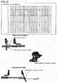
- the controller 87 stops flashing the display only when the user has performed a sufficient number of dosing steps that correspond to a Umledgehub. This indicates to the user that no precise dosing has taken place and he should discard the dispensed doses. As soon as the reversing stroke has been carried out, the control device 87 outputs via the display device 9 the set metering volume, the number of metering steps that have taken place and an arrow indicating the displacement of the receiving body 25 downwards.
- the control device 87 takes the number of required dosing for the realization of a reverse stroke for each set dosing a stored table.
- An example of such a table is in Fig. 22 specified.
- Fig. 17 to 21 can in particular by means of the pipette according to Fig. 1 to 16 be performed.
- the processes of Fig. 1 to 17 can also be carried out by means of other suitable pipettes.
Landscapes
- Health & Medical Sciences (AREA)
- Clinical Laboratory Science (AREA)
- Chemical & Material Sciences (AREA)
- Chemical Kinetics & Catalysis (AREA)
- Sampling And Sample Adjustment (AREA)
Claims (17)
- Procédé de dosage de liquide au moyen d'une pipette dotée d'un palier de dosage réglable et d'un dispositif indicateur ainsi que d'une seringue actionnable à l'aide de la pipette, dans lequel1.1 la seringue est reliée à la pipette de manière amovible,1.2 soit le palier de dosage est réglé soit le palier de dosage préréglé est conservé,1.3 le volume de dosage réglé par le biais du palier de dosage est visualisé au moyen du dispositif indicateur,1.4 le nombre maximal d'étapes de dosage réalisables à l'aide du palier de dosage réglé et de la seringue complètement remplie sans remplissage d'appoint de la seringue est visualisé au moyen du dispositif indicateur,1.5 du liquide est aspiré dans la seringue,1.6 une course de retour est exécutée après le remplissage de la seringue avec du liquide,1.7 les étapes de dosage sont effectuées, les étapes des dosage effectuées sont comptées et le nombre des étapes de dosage effectuées et/ou le nombre d'étapes de dosage encore réalisables sans remplissage d'appoint de la seringue sont déterminés et visualisés au moyen du dispositif indicateur et1.8 après l'exécution de nombre maximal d'étapes de dosage réalisables sans remplissage d'appoint de la seringue, soit la seringue est détachée de la pipette soit les étapes de 1.2 à 1.8 sont de nouveau exécutées au moyen de la même seringue, dans lequel à l'étape 1.7 le nombre d'étapes de dosage effectuées au total avec la seringue à l'aide du palier de dosage réglé est compté et/ou le nombre d'étapes de dosage encore réalisables sans remplissage d'appoint de la seringue est déterminé et visualisé au moyen du dispositif indicateur.
- Procédé selon la revendication 1, dans lequel un codage de la seringue reliée à la pipette indiquant un volume de seringue est détecté par la pipette et le volume de dosage est déterminé sur la base du palier de dosage réglé ainsi que du codage détecté et visualisé au moyen du dispositif indicateur.
- Procédé selon la revendication 1 ou 2, dans lequel un affichage signalant l'admission de liquide est visualisé au moyen du dispositif indicateur avant l'admission de liquide au moyen de la seringue reliée à la pipette de manière amovible.
- Procédé selon l'une des revendications 1 à 3, dans lequel un affichage clignotant ou signalant d'une autre manière le processus en cours de l'admission de liquide dans la seringue et de l'exécution d'une course de retour est visualisé au moyen du dispositif indicateur lors de l'admission de liquide jusqu'à l'exécution complète d'une course de retour.
- Procédé selon l'une des revendications 1 à 4, dans lequel le volume de dosage réglé et le nombre d'étapes de dosage effectuées sont visualisés au moyen du dispositif indicateur après l'exécution complète de la course de retour.
- Procédé selon la revendication 5, dans lequel un affichage signalant la distribution de liquide est visualisé après l'exécution complète de la course de retour.
- Procédé selon l'une des revendications 1 à 6, dans lequel un affichage signalant soit la distribution du liquide résiduel de la seringue et le détachement de la seringue de la pipette ou l'admission d'un autre liquide au moyen de la même seringue est visualisé au moyen du dispositif indicateur après l'exécution du nombre maximal d'étapes de dosage.
- Procédé selon la revendication 7, dans lequel un affichage signalant le détachement de la seringue de la pipette est visualisé au moyen du dispositif indicateur après la distribution du liquide résiduel de la seringue.
- Procédé selon l'une des revendications 1 à 8, dans lequel un affichage n'est visualisé au moyen du dispositif indicateur que si une seringue est reliée à la pipette de manière amovible et dans lequel l'affichage s'éteint si la seringue est détachée de la pipette.
- Procédé selon l'une des revendications 1 à 9, dans lequel après la liaison amovible de la pipette avec la seringue et avant l'admission de liquide dans la seringue, un affichage signalant le réglage de la pipette dans une position finale inférieure en vue de l'admission de liquide est visualisé au moyen du dispositif indicateur si la pipette ne se trouve pas dans la position finale inférieure en vue de l'admission de liquide.
- Procédé selon l'une des revendications 1 à 10, dans lequel après l'exécution d'une étape de dosage au moins et avant l'exécution du nombre maximal d'étapes de dosage réalisables en cas de modification du réglage du palier de dosage, le volume de dosage nouvellement réglé et le nombre maximal d'autres étapes de dosage réalisables sans remplissage d'appoint de la seringue à l'aide du volume de dosage nouvellement réglé sont visualisés au moyen du dispositif indicateur et le nombre d'autres étapes de dosage accomplies avec le volume de dosage nouvellement réglé est compté et visualisé au moyen du dispositif indicateur.
- Procédé selon la revendication 11, dans lequel après la modification du palier de dosage et la réinitialisation consécutive du palier de dosage sur la valeur préréglée, le nombre maximal d'autres étapes de dosage réalisables sans remplissage d'appoint de la seringue à l'aide du palier de dosage préalablement réglé est visualisé au moyen du dispositif indicateur et les étapes de dosage accomplies au moyen du palier de dosage nouvellement réglé après la réinitialisation ou les étapes de dosage accomplies au total avant et après la réinitialisation sont comptées et visualisées au moyen du dispositif indicateur.
- Procédé selon l'une des revendications 1 à 12, dans lequel en cas d'exécution d'étapes de dosage après l'admission incomplète de liquide dans la seringue, un affichage signalant l'accomplissement d'une course de retour est visualisé au moyen du dispositif indicateur jusqu'à ce que la course de retour soit effectuée moyennant une ou plusieurs étapes de dosage et les étapes de dosage suivantes sont comptées et visualisées au moyen du dispositif indicateur.
- Pipette destinée à actionner une seringue présentant- un boîtier (2) en forme de barre,- un logement (20) avec une ouverture (21.1) à l'extrémité inférieure du boîtier (2) pour insérer une seringue (3) dotée d'un tronçon de fixation (16) sur le bord supérieur d'un cylindre (11),- un corps de réception (25) avec un autre logement (24) et une autre ouverture (21.2) à l'extrémité inférieure dans le boîtier (2) pour insérer un autre tronçon de fixation (19) d'un piston (12) de la seringue (3),- des moyens pour maintenir de manière amovible (23, 26) le tronçon de fixation (16) dans le logement (20) et l'autre tronçon de fixation (19) dans l'autre logement (24),- des moyens pour déplacer (5, 8, 34, 37, 27) le corps de réception (25) à l'intérieur du boîtier (2) dans le sens longitudinal du boîtier (2),- qui présentent un levier de remplissage (5) actionnable à l'extérieur du boîtier (2), destiné à l'admission de liquide dans la seringue (3),- un bouton de commande (8) actionnable à l'extérieur du boîtier, destiné à la distribution progressive de liquide de la seringue (3) et- un élément de réglage (10) ajustable à l'extérieur du boîtier (2) pour régler un palier de dosage,- des moyens pour détecter (43) le palier de dosage ajusté au moyen de l'élément de réglage (10),- des moyens pour détecter (22) une seringue (3) reliée à la pipette (1) de manière amovible,- des moyens pour détecter (84) l'exécution d'une étape de dosage moyennant l'actionnement du bouton de commande (8),- un dispositif de commande électronique (87) relié aux moyens de détection (22, 43, 67, 84) et- un dispositif d'affichage électronique (9) relié au dispositif de commande électronique (87),- dans laquelle le dispositif de commande électronique (87) est tel qu'en cas de seringue (3) insérée dans la pipette (1), il détermine à l'aide du palier de dosage réglé le volume de dosage et le nombre maximal d'étapes de dosage réalisables avec le palier de dosage réglé et la seringue (3) complètement remplie sans remplissage d'appoint de la seringue (3) et qu'il les visualise au moyen du dispositif indicateur et qu'il évalue le nombre des étapes de dosage effectuées et qu'il visualise le nombre des étapes de dosage exécutées et/ou le nombre des étapes de dosage encore réalisables sans remplissage d'appoint de la seringue au moyen du dispositif indicateur (9),caractérisée par des moyens de détection (67) d'une course de retour, qui décèlent l'actionnement d'un organe de transmission (69) servant à commander la course de retour.
- Pipette selon la revendication 14, qui présente un capteur (22) pour détecter un codage indiquant le volume de seringue au niveau d'une seringue (3) reliée à la pipette (1) de manière amovible.
- Pipette selon la revendication 14 ou 15, qui présente des moyens pour détecter (81) un déplacement du corps de réception (25) dans une position finale inférieure (67) en vue de la liaison amovible de la pipette (1) avec une seringue (3) et des moyens pour détecter (67) un déplacement du corps de réception (25) dans une position finale supérieure en vue du remplissage complet d'une seringue (3), dans laquelle ces moyens de détection sont reliés au dispositif de commande électronique (87).
- Pipette selon l'une des revendications 14 à 16, dans laquelle l'organe de transmission (69) est couplé au corps de réception (25), si bien qu'il est entraîné dans la position finale supérieure lors du déplacement du corps de réception (25) et lors de la course de retour dans le sens opposé, et les moyens de détection (67) du déplacement du corps de réception (25) dans la position finale supérieure sont à la fois les moyens de détection (67) de la course de retour.
Priority Applications (2)
| Application Number | Priority Date | Filing Date | Title |
|---|---|---|---|
| EP12002849.3A EP2656916B1 (fr) | 2012-04-23 | 2012-04-23 | Procédé de dosage de liquide au moyen d'une pipette et d'une seringue ainsi que la pipette destinée à actionner une seringue pour le dosage de liquides |
| PL12002849T PL2656916T3 (pl) | 2012-04-23 | 2012-04-23 | Sposób dozowania cieczy za pomocą pipety i strzykawki oraz pipeta do uruchamiania strzykawki do dozowania cieczy |
Applications Claiming Priority (1)
| Application Number | Priority Date | Filing Date | Title |
|---|---|---|---|
| EP12002849.3A EP2656916B1 (fr) | 2012-04-23 | 2012-04-23 | Procédé de dosage de liquide au moyen d'une pipette et d'une seringue ainsi que la pipette destinée à actionner une seringue pour le dosage de liquides |
Publications (2)
| Publication Number | Publication Date |
|---|---|
| EP2656916A1 EP2656916A1 (fr) | 2013-10-30 |
| EP2656916B1 true EP2656916B1 (fr) | 2019-01-16 |
Family
ID=46045702
Family Applications (1)
| Application Number | Title | Priority Date | Filing Date |
|---|---|---|---|
| EP12002849.3A Active EP2656916B1 (fr) | 2012-04-23 | 2012-04-23 | Procédé de dosage de liquide au moyen d'une pipette et d'une seringue ainsi que la pipette destinée à actionner une seringue pour le dosage de liquides |
Country Status (2)
| Country | Link |
|---|---|
| EP (1) | EP2656916B1 (fr) |
| PL (1) | PL2656916T3 (fr) |
Families Citing this family (4)
| Publication number | Priority date | Publication date | Assignee | Title |
|---|---|---|---|---|
| DE102012011938B4 (de) | 2012-06-18 | 2015-02-05 | Eppendorf Ag | Pipette zum Betätigen einer Spritze |
| DE102014109345A1 (de) | 2014-07-04 | 2016-01-07 | Eppendorf Ag | Pipette zum Betätigen einer Spritze |
| EP3335795B1 (fr) | 2016-12-16 | 2019-03-27 | Eppendorf AG | Procédé de dosage de liquide au moyen d'une pipette et d'une seringue et pipette destinée à actionner une seringue pour le dosage de liquides |
| DE202017101008U1 (de) | 2017-02-23 | 2018-05-24 | Brand Gmbh + Co Kg | Dispenser und System zum Aufnehmen und Abgeben von Fluidvolumina |
Family Cites Families (10)
| Publication number | Priority date | Publication date | Assignee | Title |
|---|---|---|---|---|
| DE2926691C2 (de) | 1979-07-02 | 1983-05-26 | Eppendorf Gerätebau Netheler + Hinz GmbH, 2000 Hamburg | Repetierpipette |
| DE3100736A1 (de) | 1981-01-13 | 1982-08-26 | Ruhrchemie Ag, 4200 Oberhausen | Verfahren zur herstellung von traegerkatalysatoren fuer die polymerisation von (alpha)-olefinen |
| DE4341229C2 (de) | 1993-12-03 | 1995-09-07 | Eppendorf Geraetebau Netheler | Pipettensystem |
| DE4342178C2 (de) | 1993-12-10 | 1995-09-28 | Eppendorf Geraetebau Netheler | Pipettensystem |
| DE4414760C1 (de) | 1994-04-27 | 1995-08-24 | Eppendorf Geraetebau Netheler | Repetierpipette |
| DE4437716C2 (de) | 1994-10-21 | 1996-10-17 | Eppendorf Geraetebau Netheler | Repetierpipette |
| US6254832B1 (en) * | 1999-03-05 | 2001-07-03 | Rainin Instrument Co., Inc. | Battery powered microprocessor controlled hand portable electronic pipette |
| FI116613B (fi) * | 2003-10-17 | 2006-01-13 | Biohit Oyj | Pipetin kärjen kiinnitysmenetelmä ja laite menetelmän toteuttamiseksi |
| FR2874840B1 (fr) * | 2004-09-07 | 2006-11-17 | Gilson Sas Soc Par Actions Sim | Pipette comportant une roue de commande |
| DE102005023203B4 (de) | 2005-05-20 | 2009-06-04 | Eppendorf Ag | Pipette |
-
2012
- 2012-04-23 EP EP12002849.3A patent/EP2656916B1/fr active Active
- 2012-04-23 PL PL12002849T patent/PL2656916T3/pl unknown
Non-Patent Citations (1)
| Title |
|---|
| None * |
Also Published As
| Publication number | Publication date |
|---|---|
| EP2656916A1 (fr) | 2013-10-30 |
| PL2656916T3 (pl) | 2019-07-31 |
Similar Documents
| Publication | Publication Date | Title |
|---|---|---|
| DE102007010299B4 (de) | Handpipettiervorrichtung | |
| EP3164214B1 (fr) | Pipette servant à faire fonctionner une seringue | |
| EP2633913B1 (fr) | Dispositif de pipetage et dispositif de pipetage multi-canal | |
| DE102007042115B4 (de) | Pipette | |
| DE102005023203B4 (de) | Pipette | |
| EP1825915B1 (fr) | Système et procédé de titrage de liquides | |
| EP2676730B1 (fr) | Pipette destinée à actionner une seringue | |
| EP2283927B1 (fr) | Appareil électrique de dosage pour liquide | |
| EP2319623B1 (fr) | Dispositif de dosage pour liquides et procédé de dosage de liquides | |
| EP2656916B1 (fr) | Procédé de dosage de liquide au moyen d'une pipette et d'une seringue ainsi que la pipette destinée à actionner une seringue pour le dosage de liquides | |
| DE2342063B2 (de) | Mit der hand zu haltende pipette | |
| EP1598113B1 (fr) | Pipette | |
| EP3680016B1 (fr) | Pipette destinée à une utilisation avec une pointe de pipette | |
| DE2645089B2 (de) | Ausgabemechanismus für in einem Behälter enthaltene Substanzen | |
| US20160158742A1 (en) | Method for Dosing a Liquid Using a Pipette and a Syringe, and Pipette for Operating a Syringe for Dosing a Liquid | |
| CH617362A5 (fr) | ||
| EP3335795B1 (fr) | Procédé de dosage de liquide au moyen d'une pipette et d'une seringue et pipette destinée à actionner une seringue pour le dosage de liquides | |
| DE1598220B2 (de) | Automatische Pipettiervorrichtung | |
| EP2783753B1 (fr) | Distributeur destiné à actionner une seringue | |
| DE69116355T2 (de) | Prozedur zum verriegeln der verstellvorrichtung einer pipette, und pipette | |
| DE2825015A1 (de) | Fluessigkeitsuebertragungsgeraet | |
| EP3831487B1 (fr) | Pipette à utiliser avec une pointe de pipette et pointe de pipette à utiliser avec une pipette | |
| EP0046461B1 (fr) | Dispositifs de dosage pour liquides ou gaz | |
| DE102011114688A1 (de) | Handdosiervorrichtung | |
| DE2007607C3 (de) | Pipettenfüllgerät |
Legal Events
| Date | Code | Title | Description |
|---|---|---|---|
| PUAI | Public reference made under article 153(3) epc to a published international application that has entered the european phase |
Free format text: ORIGINAL CODE: 0009012 |
|
| AK | Designated contracting states |
Kind code of ref document: A1 Designated state(s): AL AT BE BG CH CY CZ DE DK EE ES FI FR GB GR HR HU IE IS IT LI LT LU LV MC MK MT NL NO PL PT RO RS SE SI SK SM TR |
|
| AX | Request for extension of the european patent |
Extension state: BA ME |
|
| 17P | Request for examination filed |
Effective date: 20140331 |
|
| RBV | Designated contracting states (corrected) |
Designated state(s): AL AT BE BG CH CY CZ DE DK EE ES FI FR GB GR HR HU IE IS IT LI LT LU LV MC MK MT NL NO PL PT RO RS SE SI SK SM TR |
|
| GRAP | Despatch of communication of intention to grant a patent |
Free format text: ORIGINAL CODE: EPIDOSNIGR1 |
|
| STAA | Information on the status of an ep patent application or granted ep patent |
Free format text: STATUS: GRANT OF PATENT IS INTENDED |
|
| RIC1 | Information provided on ipc code assigned before grant |
Ipc: B01L 3/02 20060101AFI20171103BHEP |
|
| GRAJ | Information related to disapproval of communication of intention to grant by the applicant or resumption of examination proceedings by the epo deleted |
Free format text: ORIGINAL CODE: EPIDOSDIGR1 |
|
| STAA | Information on the status of an ep patent application or granted ep patent |
Free format text: STATUS: REQUEST FOR EXAMINATION WAS MADE |
|
| INTG | Intention to grant announced |
Effective date: 20171206 |
|
| INTC | Intention to grant announced (deleted) | ||
| GRAP | Despatch of communication of intention to grant a patent |
Free format text: ORIGINAL CODE: EPIDOSNIGR1 |
|
| STAA | Information on the status of an ep patent application or granted ep patent |
Free format text: STATUS: GRANT OF PATENT IS INTENDED |
|
| INTG | Intention to grant announced |
Effective date: 20180228 |
|
| GRAJ | Information related to disapproval of communication of intention to grant by the applicant or resumption of examination proceedings by the epo deleted |
Free format text: ORIGINAL CODE: EPIDOSDIGR1 |
|
| STAA | Information on the status of an ep patent application or granted ep patent |
Free format text: STATUS: REQUEST FOR EXAMINATION WAS MADE |
|
| INTC | Intention to grant announced (deleted) | ||
| GRAP | Despatch of communication of intention to grant a patent |
Free format text: ORIGINAL CODE: EPIDOSNIGR1 |
|
| STAA | Information on the status of an ep patent application or granted ep patent |
Free format text: STATUS: GRANT OF PATENT IS INTENDED |
|
| INTG | Intention to grant announced |
Effective date: 20180530 |
|
| GRAJ | Information related to disapproval of communication of intention to grant by the applicant or resumption of examination proceedings by the epo deleted |
Free format text: ORIGINAL CODE: EPIDOSDIGR1 |
|
| STAA | Information on the status of an ep patent application or granted ep patent |
Free format text: STATUS: REQUEST FOR EXAMINATION WAS MADE |
|
| INTC | Intention to grant announced (deleted) | ||
| GRAP | Despatch of communication of intention to grant a patent |
Free format text: ORIGINAL CODE: EPIDOSNIGR1 |
|
| STAA | Information on the status of an ep patent application or granted ep patent |
Free format text: STATUS: GRANT OF PATENT IS INTENDED |
|
| GRAS | Grant fee paid |
Free format text: ORIGINAL CODE: EPIDOSNIGR3 |
|
| GRAA | (expected) grant |
Free format text: ORIGINAL CODE: 0009210 |
|
| STAA | Information on the status of an ep patent application or granted ep patent |
Free format text: STATUS: THE PATENT HAS BEEN GRANTED |
|
| INTG | Intention to grant announced |
Effective date: 20181128 |
|
| AK | Designated contracting states |
Kind code of ref document: B1 Designated state(s): AL AT BE BG CH CY CZ DE DK EE ES FI FR GB GR HR HU IE IS IT LI LT LU LV MC MK MT NL NO PL PT RO RS SE SI SK SM TR |
|
| REG | Reference to a national code |
Ref country code: GB Ref legal event code: FG4D Free format text: NOT ENGLISH |
|
| REG | Reference to a national code |
Ref country code: CH Ref legal event code: EP |
|
| REG | Reference to a national code |
Ref country code: IE Ref legal event code: FG4D Free format text: LANGUAGE OF EP DOCUMENT: GERMAN |
|
| REG | Reference to a national code |
Ref country code: DE Ref legal event code: R096 Ref document number: 502012014162 Country of ref document: DE |
|
| REG | Reference to a national code |
Ref country code: AT Ref legal event code: REF Ref document number: 1089285 Country of ref document: AT Kind code of ref document: T Effective date: 20190215 |
|
| REG | Reference to a national code |
Ref country code: DE Ref legal event code: R082 Ref document number: 502012014162 Country of ref document: DE |
|
| REG | Reference to a national code |
Ref country code: CH Ref legal event code: NV Representative=s name: BOHEST AG, CH |
|
| REG | Reference to a national code |
Ref country code: NL Ref legal event code: MP Effective date: 20190116 |
|
| REG | Reference to a national code |
Ref country code: LT Ref legal event code: MG4D |
|
| PG25 | Lapsed in a contracting state [announced via postgrant information from national office to epo] |
Ref country code: NL Free format text: LAPSE BECAUSE OF FAILURE TO SUBMIT A TRANSLATION OF THE DESCRIPTION OR TO PAY THE FEE WITHIN THE PRESCRIBED TIME-LIMIT Effective date: 20190116 |
|
| PG25 | Lapsed in a contracting state [announced via postgrant information from national office to epo] |
Ref country code: LT Free format text: LAPSE BECAUSE OF FAILURE TO SUBMIT A TRANSLATION OF THE DESCRIPTION OR TO PAY THE FEE WITHIN THE PRESCRIBED TIME-LIMIT Effective date: 20190116 Ref country code: NO Free format text: LAPSE BECAUSE OF FAILURE TO SUBMIT A TRANSLATION OF THE DESCRIPTION OR TO PAY THE FEE WITHIN THE PRESCRIBED TIME-LIMIT Effective date: 20190416 Ref country code: PT Free format text: LAPSE BECAUSE OF FAILURE TO SUBMIT A TRANSLATION OF THE DESCRIPTION OR TO PAY THE FEE WITHIN THE PRESCRIBED TIME-LIMIT Effective date: 20190516 Ref country code: SE Free format text: LAPSE BECAUSE OF FAILURE TO SUBMIT A TRANSLATION OF THE DESCRIPTION OR TO PAY THE FEE WITHIN THE PRESCRIBED TIME-LIMIT Effective date: 20190116 Ref country code: ES Free format text: LAPSE BECAUSE OF FAILURE TO SUBMIT A TRANSLATION OF THE DESCRIPTION OR TO PAY THE FEE WITHIN THE PRESCRIBED TIME-LIMIT Effective date: 20190116 |
|
| PG25 | Lapsed in a contracting state [announced via postgrant information from national office to epo] |
Ref country code: RS Free format text: LAPSE BECAUSE OF FAILURE TO SUBMIT A TRANSLATION OF THE DESCRIPTION OR TO PAY THE FEE WITHIN THE PRESCRIBED TIME-LIMIT Effective date: 20190116 Ref country code: GR Free format text: LAPSE BECAUSE OF FAILURE TO SUBMIT A TRANSLATION OF THE DESCRIPTION OR TO PAY THE FEE WITHIN THE PRESCRIBED TIME-LIMIT Effective date: 20190417 Ref country code: HR Free format text: LAPSE BECAUSE OF FAILURE TO SUBMIT A TRANSLATION OF THE DESCRIPTION OR TO PAY THE FEE WITHIN THE PRESCRIBED TIME-LIMIT Effective date: 20190116 Ref country code: LV Free format text: LAPSE BECAUSE OF FAILURE TO SUBMIT A TRANSLATION OF THE DESCRIPTION OR TO PAY THE FEE WITHIN THE PRESCRIBED TIME-LIMIT Effective date: 20190116 Ref country code: BG Free format text: LAPSE BECAUSE OF FAILURE TO SUBMIT A TRANSLATION OF THE DESCRIPTION OR TO PAY THE FEE WITHIN THE PRESCRIBED TIME-LIMIT Effective date: 20190416 Ref country code: IS Free format text: LAPSE BECAUSE OF FAILURE TO SUBMIT A TRANSLATION OF THE DESCRIPTION OR TO PAY THE FEE WITHIN THE PRESCRIBED TIME-LIMIT Effective date: 20190516 |
|
| REG | Reference to a national code |
Ref country code: DE Ref legal event code: R097 Ref document number: 502012014162 Country of ref document: DE |
|
| PG25 | Lapsed in a contracting state [announced via postgrant information from national office to epo] |
Ref country code: AL Free format text: LAPSE BECAUSE OF FAILURE TO SUBMIT A TRANSLATION OF THE DESCRIPTION OR TO PAY THE FEE WITHIN THE PRESCRIBED TIME-LIMIT Effective date: 20190116 Ref country code: CZ Free format text: LAPSE BECAUSE OF FAILURE TO SUBMIT A TRANSLATION OF THE DESCRIPTION OR TO PAY THE FEE WITHIN THE PRESCRIBED TIME-LIMIT Effective date: 20190116 Ref country code: DK Free format text: LAPSE BECAUSE OF FAILURE TO SUBMIT A TRANSLATION OF THE DESCRIPTION OR TO PAY THE FEE WITHIN THE PRESCRIBED TIME-LIMIT Effective date: 20190116 Ref country code: EE Free format text: LAPSE BECAUSE OF FAILURE TO SUBMIT A TRANSLATION OF THE DESCRIPTION OR TO PAY THE FEE WITHIN THE PRESCRIBED TIME-LIMIT Effective date: 20190116 Ref country code: IT Free format text: LAPSE BECAUSE OF FAILURE TO SUBMIT A TRANSLATION OF THE DESCRIPTION OR TO PAY THE FEE WITHIN THE PRESCRIBED TIME-LIMIT Effective date: 20190116 Ref country code: SK Free format text: LAPSE BECAUSE OF FAILURE TO SUBMIT A TRANSLATION OF THE DESCRIPTION OR TO PAY THE FEE WITHIN THE PRESCRIBED TIME-LIMIT Effective date: 20190116 Ref country code: RO Free format text: LAPSE BECAUSE OF FAILURE TO SUBMIT A TRANSLATION OF THE DESCRIPTION OR TO PAY THE FEE WITHIN THE PRESCRIBED TIME-LIMIT Effective date: 20190116 |
|
| PLBE | No opposition filed within time limit |
Free format text: ORIGINAL CODE: 0009261 |
|
| STAA | Information on the status of an ep patent application or granted ep patent |
Free format text: STATUS: NO OPPOSITION FILED WITHIN TIME LIMIT |
|
| PG25 | Lapsed in a contracting state [announced via postgrant information from national office to epo] |
Ref country code: SM Free format text: LAPSE BECAUSE OF FAILURE TO SUBMIT A TRANSLATION OF THE DESCRIPTION OR TO PAY THE FEE WITHIN THE PRESCRIBED TIME-LIMIT Effective date: 20190116 |
|
| REG | Reference to a national code |
Ref country code: BE Ref legal event code: MM Effective date: 20190430 |
|
| 26N | No opposition filed |
Effective date: 20191017 |
|
| PG25 | Lapsed in a contracting state [announced via postgrant information from national office to epo] |
Ref country code: MC Free format text: LAPSE BECAUSE OF FAILURE TO SUBMIT A TRANSLATION OF THE DESCRIPTION OR TO PAY THE FEE WITHIN THE PRESCRIBED TIME-LIMIT Effective date: 20190116 Ref country code: LU Free format text: LAPSE BECAUSE OF NON-PAYMENT OF DUE FEES Effective date: 20190423 |
|
| PG25 | Lapsed in a contracting state [announced via postgrant information from national office to epo] |
Ref country code: BE Free format text: LAPSE BECAUSE OF NON-PAYMENT OF DUE FEES Effective date: 20190430 Ref country code: SI Free format text: LAPSE BECAUSE OF FAILURE TO SUBMIT A TRANSLATION OF THE DESCRIPTION OR TO PAY THE FEE WITHIN THE PRESCRIBED TIME-LIMIT Effective date: 20190116 |
|
| PG25 | Lapsed in a contracting state [announced via postgrant information from national office to epo] |
Ref country code: TR Free format text: LAPSE BECAUSE OF FAILURE TO SUBMIT A TRANSLATION OF THE DESCRIPTION OR TO PAY THE FEE WITHIN THE PRESCRIBED TIME-LIMIT Effective date: 20190116 |
|
| PG25 | Lapsed in a contracting state [announced via postgrant information from national office to epo] |
Ref country code: IE Free format text: LAPSE BECAUSE OF NON-PAYMENT OF DUE FEES Effective date: 20190423 |
|
| REG | Reference to a national code |
Ref country code: AT Ref legal event code: MM01 Ref document number: 1089285 Country of ref document: AT Kind code of ref document: T Effective date: 20190423 |
|
| PG25 | Lapsed in a contracting state [announced via postgrant information from national office to epo] |
Ref country code: AT Free format text: LAPSE BECAUSE OF NON-PAYMENT OF DUE FEES Effective date: 20190423 |
|
| PG25 | Lapsed in a contracting state [announced via postgrant information from national office to epo] |
Ref country code: CY Free format text: LAPSE BECAUSE OF FAILURE TO SUBMIT A TRANSLATION OF THE DESCRIPTION OR TO PAY THE FEE WITHIN THE PRESCRIBED TIME-LIMIT Effective date: 20190116 |
|
| PG25 | Lapsed in a contracting state [announced via postgrant information from national office to epo] |
Ref country code: HU Free format text: LAPSE BECAUSE OF FAILURE TO SUBMIT A TRANSLATION OF THE DESCRIPTION OR TO PAY THE FEE WITHIN THE PRESCRIBED TIME-LIMIT; INVALID AB INITIO Effective date: 20120423 Ref country code: MT Free format text: LAPSE BECAUSE OF FAILURE TO SUBMIT A TRANSLATION OF THE DESCRIPTION OR TO PAY THE FEE WITHIN THE PRESCRIBED TIME-LIMIT Effective date: 20190116 |
|
| REG | Reference to a national code |
Ref country code: FR Ref legal event code: PLFP Year of fee payment: 11 |
|
| PG25 | Lapsed in a contracting state [announced via postgrant information from national office to epo] |
Ref country code: MK Free format text: LAPSE BECAUSE OF FAILURE TO SUBMIT A TRANSLATION OF THE DESCRIPTION OR TO PAY THE FEE WITHIN THE PRESCRIBED TIME-LIMIT Effective date: 20190116 |
|
| REG | Reference to a national code |
Ref country code: DE Ref legal event code: R081 Ref document number: 502012014162 Country of ref document: DE Owner name: EPPENDORF SE, DE Free format text: FORMER OWNER: EPPENDORF AG, 22339 HAMBURG, DE |
|
| P01 | Opt-out of the competence of the unified patent court (upc) registered |
Effective date: 20230527 |
|
| PGFP | Annual fee paid to national office [announced via postgrant information from national office to epo] |
Ref country code: FI Payment date: 20250424 Year of fee payment: 14 |
|
| PGFP | Annual fee paid to national office [announced via postgrant information from national office to epo] |
Ref country code: PL Payment date: 20250411 Year of fee payment: 14 Ref country code: DE Payment date: 20250422 Year of fee payment: 14 |
|
| PGFP | Annual fee paid to national office [announced via postgrant information from national office to epo] |
Ref country code: GB Payment date: 20250423 Year of fee payment: 14 |
|
| PGFP | Annual fee paid to national office [announced via postgrant information from national office to epo] |
Ref country code: FR Payment date: 20250425 Year of fee payment: 14 |
|
| PGFP | Annual fee paid to national office [announced via postgrant information from national office to epo] |
Ref country code: CH Payment date: 20250501 Year of fee payment: 14 |