EP2656920B1 - Separateur magnetique du type a tambour rotatif comprenant un dispositif permettant de supprimer l'obstruction de fente - Google Patents
Separateur magnetique du type a tambour rotatif comprenant un dispositif permettant de supprimer l'obstruction de fente Download PDFInfo
- Publication number
- EP2656920B1 EP2656920B1 EP11852023.8A EP11852023A EP2656920B1 EP 2656920 B1 EP2656920 B1 EP 2656920B1 EP 11852023 A EP11852023 A EP 11852023A EP 2656920 B1 EP2656920 B1 EP 2656920B1
- Authority
- EP
- European Patent Office
- Prior art keywords
- rotating
- opening
- slit
- cleaning member
- magnetic separator
- Prior art date
- Legal status (The legal status is an assumption and is not a legal conclusion. Google has not performed a legal analysis and makes no representation as to the accuracy of the status listed.)
- Active
Links
- 239000006148 magnetic separator Substances 0.000 title claims description 27
- 238000004140 cleaning Methods 0.000 claims description 62
- 230000007246 mechanism Effects 0.000 claims description 34
- 239000007788 liquid Substances 0.000 claims description 22
- 239000002826 coolant Substances 0.000 claims description 9
- 230000005540 biological transmission Effects 0.000 claims description 7
- 239000002245 particle Substances 0.000 description 37
- 239000010802 sludge Substances 0.000 description 11
- 238000011084 recovery Methods 0.000 description 6
- 230000003247 decreasing effect Effects 0.000 description 5
- 238000001179 sorption measurement Methods 0.000 description 4
- 229910001220 stainless steel Inorganic materials 0.000 description 4
- 239000010935 stainless steel Substances 0.000 description 4
- 238000012423 maintenance Methods 0.000 description 3
- 239000000463 material Substances 0.000 description 3
- BGPVFRJUHWVFKM-UHFFFAOYSA-N N1=C2C=CC=CC2=[N+]([O-])C1(CC1)CCC21N=C1C=CC=CC1=[N+]2[O-] Chemical compound N1=C2C=CC=CC2=[N+]([O-])C1(CC1)CCC21N=C1C=CC=CC1=[N+]2[O-] BGPVFRJUHWVFKM-UHFFFAOYSA-N 0.000 description 2
- 238000003825 pressing Methods 0.000 description 2
- 230000001105 regulatory effect Effects 0.000 description 2
- 229910052779 Neodymium Inorganic materials 0.000 description 1
- 229910000831 Steel Inorganic materials 0.000 description 1
- 238000013459 approach Methods 0.000 description 1
- 238000005452 bending Methods 0.000 description 1
- 230000008859 change Effects 0.000 description 1
- 230000001419 dependent effect Effects 0.000 description 1
- 230000000694 effects Effects 0.000 description 1
- 230000004907 flux Effects 0.000 description 1
- 239000000696 magnetic material Substances 0.000 description 1
- 238000007885 magnetic separation Methods 0.000 description 1
- 239000007769 metal material Substances 0.000 description 1
- 238000000034 method Methods 0.000 description 1
- 238000012986 modification Methods 0.000 description 1
- 230000004048 modification Effects 0.000 description 1
- QEFYFXOXNSNQGX-UHFFFAOYSA-N neodymium atom Chemical compound [Nd] QEFYFXOXNSNQGX-UHFFFAOYSA-N 0.000 description 1
- 230000008569 process Effects 0.000 description 1
- 238000012545 processing Methods 0.000 description 1
- 239000010959 steel Substances 0.000 description 1
Images



Classifications
-
- B—PERFORMING OPERATIONS; TRANSPORTING
- B03—SEPARATION OF SOLID MATERIALS USING LIQUIDS OR USING PNEUMATIC TABLES OR JIGS; MAGNETIC OR ELECTROSTATIC SEPARATION OF SOLID MATERIALS FROM SOLID MATERIALS OR FLUIDS; SEPARATION BY HIGH-VOLTAGE ELECTRIC FIELDS
- B03C—MAGNETIC OR ELECTROSTATIC SEPARATION OF SOLID MATERIALS FROM SOLID MATERIALS OR FLUIDS; SEPARATION BY HIGH-VOLTAGE ELECTRIC FIELDS
- B03C1/00—Magnetic separation
- B03C1/02—Magnetic separation acting directly on the substance being separated
- B03C1/10—Magnetic separation acting directly on the substance being separated with cylindrical material carriers
- B03C1/14—Magnetic separation acting directly on the substance being separated with cylindrical material carriers with non-movable magnets
-
- B—PERFORMING OPERATIONS; TRANSPORTING
- B03—SEPARATION OF SOLID MATERIALS USING LIQUIDS OR USING PNEUMATIC TABLES OR JIGS; MAGNETIC OR ELECTROSTATIC SEPARATION OF SOLID MATERIALS FROM SOLID MATERIALS OR FLUIDS; SEPARATION BY HIGH-VOLTAGE ELECTRIC FIELDS
- B03C—MAGNETIC OR ELECTROSTATIC SEPARATION OF SOLID MATERIALS FROM SOLID MATERIALS OR FLUIDS; SEPARATION BY HIGH-VOLTAGE ELECTRIC FIELDS
- B03C1/00—Magnetic separation
- B03C1/02—Magnetic separation acting directly on the substance being separated
- B03C1/30—Combinations with other devices, not otherwise provided for
-
- B—PERFORMING OPERATIONS; TRANSPORTING
- B03—SEPARATION OF SOLID MATERIALS USING LIQUIDS OR USING PNEUMATIC TABLES OR JIGS; MAGNETIC OR ELECTROSTATIC SEPARATION OF SOLID MATERIALS FROM SOLID MATERIALS OR FLUIDS; SEPARATION BY HIGH-VOLTAGE ELECTRIC FIELDS
- B03C—MAGNETIC OR ELECTROSTATIC SEPARATION OF SOLID MATERIALS FROM SOLID MATERIALS OR FLUIDS; SEPARATION BY HIGH-VOLTAGE ELECTRIC FIELDS
- B03C1/00—Magnetic separation
- B03C1/02—Magnetic separation acting directly on the substance being separated
- B03C1/23—Magnetic separation acting directly on the substance being separated with material carried by oscillating fields; with material carried by travelling fields, e.g. generated by stationary magnetic coils; Eddy-current separators, e.g. sliding ramp
- B03C1/24—Magnetic separation acting directly on the substance being separated with material carried by oscillating fields; with material carried by travelling fields, e.g. generated by stationary magnetic coils; Eddy-current separators, e.g. sliding ramp with material carried by travelling fields
- B03C1/247—Magnetic separation acting directly on the substance being separated with material carried by oscillating fields; with material carried by travelling fields, e.g. generated by stationary magnetic coils; Eddy-current separators, e.g. sliding ramp with material carried by travelling fields obtained by a rotating magnetic drum
-
- B—PERFORMING OPERATIONS; TRANSPORTING
- B03—SEPARATION OF SOLID MATERIALS USING LIQUIDS OR USING PNEUMATIC TABLES OR JIGS; MAGNETIC OR ELECTROSTATIC SEPARATION OF SOLID MATERIALS FROM SOLID MATERIALS OR FLUIDS; SEPARATION BY HIGH-VOLTAGE ELECTRIC FIELDS
- B03C—MAGNETIC OR ELECTROSTATIC SEPARATION OF SOLID MATERIALS FROM SOLID MATERIALS OR FLUIDS; SEPARATION BY HIGH-VOLTAGE ELECTRIC FIELDS
- B03C1/00—Magnetic separation
- B03C1/02—Magnetic separation acting directly on the substance being separated
- B03C1/28—Magnetic plugs and dipsticks
-
- B—PERFORMING OPERATIONS; TRANSPORTING
- B03—SEPARATION OF SOLID MATERIALS USING LIQUIDS OR USING PNEUMATIC TABLES OR JIGS; MAGNETIC OR ELECTROSTATIC SEPARATION OF SOLID MATERIALS FROM SOLID MATERIALS OR FLUIDS; SEPARATION BY HIGH-VOLTAGE ELECTRIC FIELDS
- B03C—MAGNETIC OR ELECTROSTATIC SEPARATION OF SOLID MATERIALS FROM SOLID MATERIALS OR FLUIDS; SEPARATION BY HIGH-VOLTAGE ELECTRIC FIELDS
- B03C1/00—Magnetic separation
- B03C1/02—Magnetic separation acting directly on the substance being separated
- B03C1/28—Magnetic plugs and dipsticks
- B03C1/284—Magnetic plugs and dipsticks with associated cleaning means, e.g. retractable non-magnetic sleeve
-
- B—PERFORMING OPERATIONS; TRANSPORTING
- B03—SEPARATION OF SOLID MATERIALS USING LIQUIDS OR USING PNEUMATIC TABLES OR JIGS; MAGNETIC OR ELECTROSTATIC SEPARATION OF SOLID MATERIALS FROM SOLID MATERIALS OR FLUIDS; SEPARATION BY HIGH-VOLTAGE ELECTRIC FIELDS
- B03C—MAGNETIC OR ELECTROSTATIC SEPARATION OF SOLID MATERIALS FROM SOLID MATERIALS OR FLUIDS; SEPARATION BY HIGH-VOLTAGE ELECTRIC FIELDS
- B03C1/00—Magnetic separation
- B03C1/02—Magnetic separation acting directly on the substance being separated
- B03C1/28—Magnetic plugs and dipsticks
- B03C1/286—Magnetic plugs and dipsticks disposed at the inner circumference of a recipient, e.g. magnetic drain bolt
-
- B—PERFORMING OPERATIONS; TRANSPORTING
- B23—MACHINE TOOLS; METAL-WORKING NOT OTHERWISE PROVIDED FOR
- B23Q—DETAILS, COMPONENTS, OR ACCESSORIES FOR MACHINE TOOLS, e.g. ARRANGEMENTS FOR COPYING OR CONTROLLING; MACHINE TOOLS IN GENERAL CHARACTERISED BY THE CONSTRUCTION OF PARTICULAR DETAILS OR COMPONENTS; COMBINATIONS OR ASSOCIATIONS OF METAL-WORKING MACHINES, NOT DIRECTED TO A PARTICULAR RESULT
- B23Q11/00—Accessories fitted to machine tools for keeping tools or parts of the machine in good working condition or for cooling work; Safety devices specially combined with or arranged in, or specially adapted for use in connection with, machine tools
Definitions
- the present invention relates to a rotating-drum type magnetic separator comprising a device for suppressing slit clogging which cleans a slit of the rotating-drum type magnetic separator which separates and recovers sludge included in used coolant liquid.
- JP 2007-000978 A discloses a rotating-drum type magnetic separator in the related art.
- Fig. 1 shows a configuration of the rotating-drum type magnetic separator in the related art and is a cross-sectional view at a surface perpendicular to a rotational axis of a rotating drum.
- a liquid reservoir portion 10 which stores coolant liquid in a box type main body is provided.
- a rotating drum 3 is supported in an approximately horizontal direction in the vicinity of the center portion of the main body.
- the rotating drum 3 is a cylindrical body which is formed of a nonmagnetic material such as stainless steel, and an inner cylinder 5, in which a plurality of magnets 4, 4, ... are disposed on the outer circumferential surface in a predetermined arrangement, is coaxially fixed to the inner portion of an outer cylinder. Polarities of the plurality of magnets 4, 4, ... are disposed so as to generate a predetermined magnetic flux in the vicinity of the outer circumference surface of the rotating drum 3, so that scrap, chips, or the like which are magnetic bodies contained in the coolant liquid are magnetically attached.
- JP 2007-000978 A the plurality of magnets 4, 4, ... are disposed between a portion in which the rotating drum 3 starts to be immersed in the liquid reservoir portion 10 and the top, that is, on the inner cylinder 5 corresponding to a portion equivalent to approximately 3/4 of the outer circumferential surface of the rotating drum 3.
- the magnet 4 is not disposed on the inner cylinder 5 in the portion corresponding to the remaining approximately 1/4, and a magnetic force is not applied on the portion.
- Sludge which is adsorbed on the outer circumference surface of the rotating drum 3 on the bottom portion of the liquid reservoir portion 10 by application of the magnetic force of the plurality of magnets 4, 4, ... is transported to the top of the rotating drum 3 according to the rotation of the rotating drum 3.
- adsorption forces generated due to the magnetic forces of the plurality of magnets 4, 4, ... are lost, and the sludge is scratched away by a scraper 7 abutting on the rotating drum 3 and is recovered.
- the adsorbed sludge passes through between the rotating drum 3 and the squeezing roller 6, and thus, liquid contained in the sludge is squeezed, and only the scrap, chips, or the like is separated at the position in which the magnetic force does not reach.
- a slit-like opening 8 is provided on the bottom portion of a magnetic field channel 16 along the outer circumference surface of the rotating drum 3.
- the opening 8 is provided, and thus, it is possible to increase recovery rates of the scrap, chips, or the like while maintaining the recovery rate of the ground particles.
- JP 2007-000978 A the ground particles are recovered from the slit-like opening 8.
- nonmagnetic particles or the like larger than an opening width are clogged in the opening 8, and there is a problem that the recovery rates of the ground particles may be largely decreased.
- work to clean at fixed intervals is troublesome, and there is a concern that work efficiency in the entire process may be decreased.
- the present invention is made in consideration of the above-described circumstances, and an object thereof is to provide a rotating-drum type magnetic separator comprising a device for suppressing slit clogging capable of maintaining recovery rates of ground particles without clogging of the ground particles in the opening.
- a rotating-drum type magnetic separator comprising a device for suppressing slit clogging as set forth in claim 1.
- Preferred embodiments of the present invention may be gathered from the dependent claims.
- the slit cleaning member moves along the longitudinal direction of the slit-like opening, and thus, it is possible to suppress the opening from being clogged due to the ground particles.
- Fig. 2 shows a configuration of a rotating-drum type magnetic separator which uses a device for suppressing slit clogging according to Embodiment 1 of the present invention and is a cross-sectional view at a surface perpendicular to a rotational axis of a rotating drum.
- a liquid reservoir portion 10 which stores coolant liquid in a box type main body is provided.
- a rotating drum 3 is rotatably supported by a rotating shaft 31 in an approximately horizontal direction in the vicinity of the center portion of the main body.
- the rotating drum 3 is a cylindrical body, which is formed of a nonmagnetic material such as stainless steel, and an inner cylinder 5, in which a plurality of magnets 4, 4, ... are disposed, is coaxially fixed by the rotating shaft 31 in the inner portion on the outer circumferential surface of the rotating drum 3.
- the plurality of magnets 4, 4, ... disposed on the inner cylinder 5 are disposed by appropriately adjusting magnetic poles so as to apply a necessary magnetic force to the outer circumferential surface of the rotating drum 3.
- a neodymium-based magnet is used for the magnet 4, N and S become a pair, and the magnets are disposed in the order of N, S, N, S from one end of a squeezing roller 6 side.
- a range where the magnetic force is applied to the rotating drum 3 is changed according to an outer diameter of the drum, a position of a scraper 7, or the like.
- the magnets 4, 4, ... are disposed on the inner cylinder 5 so that adsorption force reaches a range of an approximately 3/4 of the outer circumference surface, that is from a portion in which the rotating drum 3 starts to be immersed in the liquid reservoir portion 10 to the top, and the magnets are not disposed on the inner cylinder 5 in a range of the remaining approximately 1/4 of the outer circumferential surface.
- the sludge containing scrap, chips, or the like which are adsorbed to the outer circumferential surface of the rotating drum 3 in a magnetic field channel 16 to which the magnetic force is applied, is transported up to the top of the rotating drum 3 by the rotation of the rotating drum 3.
- the squeezing roller 6 is disposed in the vicinity of the top of the rotating drum 3, and is abutted on the outer circumferential surface of the rotating drum 3 by a predetermined pressing force.
- the liquid which is contained in the sludge which is adsorbed to the outer circumferential surface of the rotating drum 3 and transported, is squeezed by the squeezing roller 6.
- the scrap, chips, or the like, in which liquid is squeezed pass the top, the scrap, chips, or the like are released from the adsorption force due to the magnetic forces of the magnets 4, 4, ..., scraped by the plate-like scraper 7 abutting on the outer circumferential surface of the rotating drum 3, and recovered.
- the coolant liquid passes through the magnetic field channel 16 which is formed by the rotating drum 3 and a casing bottom plate 9 disposed along the rotating drum 3.
- the coolant liquid passes through the magnetic field channel 16, and thus, the scrap, chips, or the like which are mixed in the liquid are separated and recovered.
- an opening 8 is provided at a position of the magnetic field channel 16 opposite to the outer cylinder of the rotating drum 3.
- the opening 8 has a parallel slit shape which is perpendicular to the rotation direction of the rotating shaft 31 of the rotating drum 3.
- the opening 8 is manufactured by processing stainless steel (SUS 304) having a flat plate shape at first by a laser or a turret punch so as to form a constant opening width in a thickness direction, and thereafter, by bending the stainless steel in an arc shape.
- FIG. 3 is a plan view showing the configuration of the device for suppressing slit clogging 2 according to Embodiment 1 of the present invention.
- Fig. 3 is a view when the bottom surface of the rotating-drum type magnetic separator 1 is viewed from the bottom surface side.
- a cylindrical groove cam mechanism which is configured by a cylindrical shaft 21 having a groove which can be rotated and a slit cleaning member 22 which engages with the groove, is provided below the opening 8 as a moving mechanism which moves the slit cleaning member 22.
- the cylindrical shaft 21 is provided so as to be approximately parallel in the longitudinal direction of the slit-like opening 8 and is disposed at a position which is deviated in the rotation direction of the rotating drum 3 from immediately below the opening 8. Since the cylindrical shaft is deviated from immediately below the opening 8, the movement of the slit cleaning member 22 is not regulated by the ground particles which are discharged from the opening 8.
- the slit cleaning member 22 moves along the longitudinal direction of the opening 8 on the shaft 21.
- the slit cleaning member 22 moves, and thus, a slit cleaning pin 23 provided on the tip of the slit cleaning member 22 reciprocates along the longitudinal direction of the opening 8 in the slit-like opening 8, and the ground particles which are accumulated in the vicinity of the opening 8 can be effectively removed.
- a plate-like member 28 is mounted so as to be approximately parallel in the longitudinal direction of the opening 8 between the shaft 21 and the slit-like opening 8. The reason is because the possibility that the ground particles discharged from the opening 8 may be guided to the cylindrical groove cam mechanism is decreased, and thus, the ground particles can be stably separated and recovered.
- the groove included in the cylindrical shaft 21 is formed in a cross screw shape, and a protrusion of the slit cleaning member 22 is connected so as to be engaged with the groove.
- the slit cleaning member 22 moves along the longitudinal direction of the opening 8 in the slit-like opening 8 according to the rotation of the shaft 21.
- the slit cleaning member 22 moves along the longitudinal direction of the opening 8 according to the rotation of the shaft 21, and thus, the clogging of the ground particles in the opening 8 can be suppressed, and the ground particles can be separated and recovered in free maintenance.
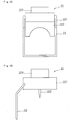
- Fig. 4 is a front view and a side view showing a configuration of the slit cleaning member 22 of the device for suppressing slit clogging 2 according to Embodiment 1 of the present invention.
- Fig. 4(a) is a front view showing the configuration of the slit cleaning member 22 of the device for suppressing slit clogging 2 according to Embodiment 1 of the present invention
- Fig. 4(b) is a side view showing the configuration of the slit cleaning member 22 of the device for suppressing slit clogging 2 according to Embodiment 1 of the present invention.
- the slit cleaning member 22 is connected to a main body portion 221 which reciprocates along the longitudinal direction of the opening 8 on the cylindrical shaft 21 so as to reciprocate on the shaft 21 via a protrusion 222 which engages with the groove of the shaft 21 and a fixed portion 223.
- the slit cleaning pin 23 has a shape which is curved toward the outside of the main body portion 221 so as to be inserted into the opening 8 at a position separate from the protrusion 222 which engages with the groove of the shaft 21.
- the shape of the slit cleaning pin 23 is not limited to the shape shown in Fig. 4 , and may have any shape if the slit cleaning pin 23 can be inserted into the slit-like opening 8 without disposing the shaft 21 at the position which is deviated from immediately below the opening 8.
- a power source which rotates the shaft 21 is made to be common to a power source which rotates the rotating drum 3. That is, a rotation transmission mechanism which transmits the rotation of the rotating shaft 31 to the shaft 21 is provided on at least one end of the rotating shaft 31 of the rotating drum 3. Thereby, it is not necessary to separately provide the power source so as to clean the slit-like opening 8 and suppress clogging of the ground particles, the shaft 21 is rotated by the power source which rotates the rotating drum 3, and thus, clogging of the ground particles in the opening 8 can be suppressed by moving the slit cleaning member 22.
- a chain unit 41 is mounted on at least one end of the shaft 21, and continuous protrusions 42 which can engage with the chain unit 41 are provided on at least one end of the rotating shaft 31 of the rotating drum 3.
- the rotating shaft 31 of the rotating drum 3 is rotated in a counterclockwise direction, and thus, the chain unit 41, which engages with the plurality of continuous protrusions 42, 42, ..., is rotated in a clockwise direction.
- the chain unit 41 is rotated in a clockwise direction, and thus, the shaft 21 is also rotated in a clockwise direction.
- the slit cleaning member 22 linearly moves along any direction of the longitudinal direction of the opening 8.
- the protrusion 222 of the slit cleaning member 22 reaches one end of the opening 8, since the groove is formed in a cross screw shape, without a change in the rotation direction of the shaft 21, the protrusion 222 of the slit cleaning member 22 linearly moves from the one end of the opening 8 in which the protrusion has reached toward the opposite direction. Therefore, since the slit cleaning member 22 moves along the longitudinal direction of the slit-like opening 8 while the rotating drum 3 is continuously rotated, clogging of the ground particles in the opening 8 can be suppressed, and the ground particles can be separated and recovered in free maintenance.
- the cylindrical groove cam mechanism can be operated by the power source which rotates the rotating drum 3 via a simple mechanism such as the chain unit 41, it is not necessary to separately provide the power source so as to clean the slit-like opening 8 and suppress the clogging of the ground particles.
- Embodiment 2 A configuration of the rotating-drum type magnetic separator 1 itself which uses a device for suppressing slit clogging according to Embodiment 2 of the present invention is similar to the configuration in the related art (refer to Fig. 1 ), the same reference numerals are attached, and the detailed descriptions are omitted.
- Embodiment 2 is different from Embodiment 1 in that clogging of the ground particles are suppressed by cleaning the slit-like opening 8 manually.
- Fig. 5 is a plan view showing a configuration of the device for suppressing slit clogging 2 according to Embodiment 2 of the present invention.
- Fig. 5 is a view when the bottom surface of the rotating-drum type magnetic separator 1 is viewed from the bottom surface side.
- a cylindrical groove cam mechanism which is configured by the cylindrical shaft 21 having a groove which can be rotated and the slit cleaning member 22 which engages with the groove, is provided below the opening 8.
- the cylindrical shaft 21 is provided so as to be approximately parallel in the longitudinal direction of the slit-like opening 8 and is disposed at a position which is deviated in the rotation direction of the rotating drum 3 from immediately below the opening 8. Since the cylindrical shaft is deviated from immediately below the opening 8, the movement of the slit cleaning member 22 is not regulated by the ground particles which are discharged from the opening 8.
- a groove having an internal screw shape is formed on the cylindrical shaft 21, and the protrusion 222 having an external screw shape is formed on the slit cleaning member 22.
- the groove of the shaft 21 and the protrusion 222 of the slit cleaning member 22 is connected so as to be engaged with each other, and the slit cleaning member 22 moves along the longitudinal direction of the slit-like opening 8 according to the rotation of the shaft 21.
- An operating handle 51 which can rotate the shaft 21 manually is provided on one end of the shaft 21.
- the shaft 21 is also rotated in a clockwise direction.
- the slit cleaning member 22 linearly moves in a direction which approaches the operation handle 51 along the longitudinal direction of the opening 8.
- the shaft 21 is also rotated in a counterclockwise direction. According to the rotation of the shaft 21, the slit cleaning member 22 linearly moves in a direction separate from the operating handle 51 along the longitudinal direction of the opening 8 via the protrusion 222 which engages with the groove of the shaft 21.
- the slit cleaning pin 23 provided on the tip of the slit cleaning member 22 reciprocates along the longitudinal direction of the opening 8 in the slit-like opening 8, the ground particles which are accumulated in the vicinity of the opening 8 can be effectively removed.
- the plate-like member 28 is mounted so as to be approximately parallel in the longitudinal direction of the opening 8 between the shaft 21 and the slit-like opening 8. The reason is because the possibility that the ground particles discharged from the opening 8 may be guided to the cylindrical groove cam mechanism is decreased, and thus, the ground particles can be stably separated and recovered.
- the cylindrical groove cam mechanism in the cylindrical groove cam mechanism, the groove which is formed in an internal screw shape and the protrusion 222 of the slit cleaning member 22 which is formed in an external screw shape is connected so as to be engaged with each other.
- the slit cleaning member 22 moves along the longitudinal direction of the slit-like opening 8 according to the rotation of the shaft 21, and thus, the clogging of the ground particles in the slit-like opening 8 can be suppressed, and the ground particles can be separated and recovered in free maintenance.
- the cylindrical groove cam mechanism can be operated manually, it is not necessary to provide a power source separately from the power source which rotates the rotating drum 3 so as to clean the slit-like opening 8 and suppress the clogging of the ground particles.
- Embodiment 3 A configuration of the rotating-drum type magnetic separator 1 itself which uses a device for suppressing slit clogging according to Embodiment 3 of the present invention is similar to the configuration in the related art (refer to Fig. 1 ), the same reference numerals are attached, and the detailed descriptions are omitted.
- Embodiment 3 is different from Embodiments 1 and 2 in that the moving mechanism which moves the slit cleaning member 22 is a circular member which is wound around two columnar members.
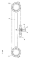
- FIG. 6 is a plan view showing a configuration of the device for suppressing slit clogging 2 according to Embodiment 3 of the present invention.
- Fig. 6 is a view when the bottom surface of the rotating-drum type magnetic separator 1 is viewed from the bottom surface side.
- a moving mechanism which is configured by two columnar members 61 and 61 which can be rotated and an annular member 62 which is wound around the columnar members 61 and 61, is provided below the opening 8.
- two sprockets are used as the columnar members 61 and 61
- a chain belt is used as the annular member 62
- the slit cleaning member 22 is fixed to a portion of the chain belt.
- the invention is not limited to the combination of the sprocket and the chain belt, and any configuration such as a combination of a roller and a belt may be adopted if the annular member 62 moves according to the rotation of two columnar members 61 and 61.
- the annular member 62 moves in any direction of arrow directions of Fig. 6 .
- the annular member 62 moves in an arrow A direction
- the annular member 62 moves in an arrow B direction.
- the slit cleaning member 22 which is fixed to the annular member 62 also moves along the longitudinal direction of the slit-like opening 8. Since a portion of the slit cleaning member 22 is inserted into the opening 8, the ground particles which are accumulated in the vicinity of the opening 8 can be effectively removed.
- the present invention is not limited the above-described embodiments, and various modifications, improvements, or the like are possible within the scope of the present invention as defined by the appended claims.
- the rotation transmission mechanism the configuration is described in which the chain unit 41 is mounted on at least one end of the shaft 21 and the continuous protrusions 42 which can engage with the chain unit 41 are provided on at least one end of the rotating shaft 31 of the rotating drum 3.
- the chain units 41 may be provided on both ends of the shaft 21, and in addition to the chain unit, if the rotation transmission mechanism can transmit a rotation such as a gear mechanism or a belt mechanism, the rotation transmission mechanism is not particularly limited.
Landscapes
- Engineering & Computer Science (AREA)
- Mechanical Engineering (AREA)
- Auxiliary Devices For Machine Tools (AREA)
- Cleaning In General (AREA)
- Combined Means For Separation Of Solids (AREA)
Claims (9)
- Séparateur magnétique de type à tambour rotatif (1) qui comporte un tambour rotatif (3) sur lequel une pluralité d'aimants (4) sont disposés et qui sépare des matières inutiles dans un liquide de refroidissement traité,
dans lequel une ouverture en forme de fente (8) est prévue sous le tambour rotatif (3), ledit séparateur magnétique (1) étant caractérisé en ce qu'il comprend un dispositif destiné à supprimer un colmatage de fente (2),
dans lequel le dispositif destiné à supprimer un colmatage de fente (2) comprend un élément de nettoyage de fente (22), dont une partie (23) est insérée dans l'ouverture (8), ledit élément de nettoyage de fente (22) étant agencé de sorte à être mobile le long d'une direction longitudinale de l'ouverture (8). - Séparateur magnétique de type à tambour rotatif (1) selon la revendication 1,
dans lequel un mécanisme de déplacement (21, 61, 62) qui est agencé pour déplacer l'élément de nettoyage de fente (22) est disposé de sorte à être approximativement parallèle à l'ouverture (8) et en une position distincte d'immédiatement sous l'ouverture (8) . - Séparateur magnétique de type à tambour rotatif (1) selon la revendication 2,
dans lequel un élément en forme de plaque (28) est monté de sorte à être approximativement parallèle à l'ouverture (8) entre le mécanisme de déplacement (21, 61, 62) et l'ouverture (8). - Séparateur magnétique de type à tambour rotatif (1) selon l'une quelconque des revendications 1 à 3,
dans lequel un mécanisme de came à rainure cylindrique, qui est configuré par un arbre cylindrique (21) ayant une rainure qui peut être tournée et l'élément de nettoyage de fente (22) qui s'engage avec la rainure, est prévu sous l'ouverture (8) en tant que le mécanisme de déplacement. - Séparateur magnétique de type à tambour rotatif (1) selon la revendication 4,
dans lequel, dans le mécanisme de came à rainure cylindrique, la rainure qui est formée en forme de vis interne et une saillie (222) de l'élément de nettoyage de fente (22) qui est formée en forme de vis externe sont connectées de sorte à être engagées l'une avec l'autre, de sorte que l'élément de nettoyage de fente (22) se déplace le long de la direction longitudinale de l'ouverture (8) en fonction d'une rotation de l'arbre (21). - Séparateur magnétique de type à tambour rotatif (1) selon la revendication 4 ou 5,
dans lequel, dans le mécanisme de came à rainure cylindrique, la rainure est formée en forme de vis cruciforme et la saillie (222) de l'élément de nettoyage de la fente (22) est connectée de sorte à être engagée avec la rainure, de sorte que l'élément de nettoyage de fente (22) se déplace le long de la direction longitudinale de l'ouverture (8) en fonction de la rotation de l'arbre (21). - Séparateur magnétique de type à tambour rotatif (1) selon la revendication 6,
dans lequel un mécanisme de transmission de rotation (41, 42), qui transmet une rotation d'un arbre rotatif (31) du tambour rotatif (3) à l'arbre cylindrique (21) du mécanisme de came à rainure cylindrique, est prévu sur au moins une extrémité de l'arbre rotatif (31) du tambour rotatif (3), de sorte que le mécanisme de came à rainure cylindrique est actionné par la rotation du tambour rotatif (3). - Séparateur magnétique de type à tambour rotatif (1) selon la revendication 7,
dans lequel, dans le mécanisme de transmission de rotation, une unité de chaîne (41) est montée sur au moins une extrémité de l'arbre cylindrique (21) du mécanisme de came à rainure cylindrique, et des saillies continues (42) qui peuvent s'engager avec l'unité de chaîne (41) sont prévues sur au moins une extrémité de l'arbre rotatif (31) du tambour rotatif (3). - Séparateur magnétique de type à tambour rotatif (1) selon la revendication 1,
dans lequel deux éléments en colonne (61) qui peuvent tourner et un élément annulaire (62) qui est enroulé autour des éléments en colonne (61) sont prévus sous l'ouverture (8) en tant qu'un mécanisme de déplacement, et
dans lequel l'élément de nettoyage de fente (22) est fixé à une partie de l'élément annulaire (62).
Applications Claiming Priority (2)
| Application Number | Priority Date | Filing Date | Title |
|---|---|---|---|
| JP2010286997A JP4912497B1 (ja) | 2010-12-24 | 2010-12-24 | スリット詰まり抑制装置 |
| PCT/JP2011/078847 WO2012086475A1 (fr) | 2010-12-24 | 2011-12-14 | Dispositif de limitation d'obstruction de fente |
Publications (3)
| Publication Number | Publication Date |
|---|---|
| EP2656920A1 EP2656920A1 (fr) | 2013-10-30 |
| EP2656920A4 EP2656920A4 (fr) | 2016-01-13 |
| EP2656920B1 true EP2656920B1 (fr) | 2020-03-04 |
Family
ID=46170953
Family Applications (1)
| Application Number | Title | Priority Date | Filing Date |
|---|---|---|---|
| EP11852023.8A Active EP2656920B1 (fr) | 2010-12-24 | 2011-12-14 | Separateur magnetique du type a tambour rotatif comprenant un dispositif permettant de supprimer l'obstruction de fente |
Country Status (7)
| Country | Link |
|---|---|
| US (1) | US9023199B2 (fr) |
| EP (1) | EP2656920B1 (fr) |
| JP (1) | JP4912497B1 (fr) |
| KR (1) | KR101470771B1 (fr) |
| CN (1) | CN103249491B (fr) |
| TW (1) | TWI473656B (fr) |
| WO (1) | WO2012086475A1 (fr) |
Families Citing this family (10)
| Publication number | Priority date | Publication date | Assignee | Title |
|---|---|---|---|---|
| DE112013005800B4 (de) | 2012-12-04 | 2021-11-11 | Evoqua Water Technologies Llc | Einlassgleitfläche und Schaberklinge für eine Magnettrommel |
| JP6259409B2 (ja) * | 2015-03-19 | 2018-01-10 | Primetals Technologies Japan株式会社 | 磁性物除去装置および磁性物除去方法 |
| WO2019064847A1 (fr) | 2017-09-27 | 2019-04-04 | 住友重機械ファインテック株式会社 | Séparateur magnétique |
| WO2019073662A1 (fr) | 2017-10-13 | 2019-04-18 | 住友重機械ファインテック株式会社 | Dispositif de traitement de liquide de refroidissement |
| CN109822389A (zh) * | 2019-02-16 | 2019-05-31 | 宁夏共享机床辅机有限公司 | 一种磁性分离装置 |
| JP7146685B2 (ja) * | 2019-03-29 | 2022-10-04 | 住友重機械ファインテック株式会社 | ドラム型分離装置 |
| CN110694795B (zh) * | 2019-10-21 | 2021-01-01 | 广东省车汇莱再生物资回收有限公司 | 一种废机油回收再利用处理方法 |
| EP4034506A4 (fr) | 2019-11-08 | 2023-07-26 | Evoqua Water Technologies LLC | Sédimentation accélérée de flocs après électrocoagulation/processus électrochimique à l'aide d'une floculation lestée |
| JP7696725B2 (ja) * | 2021-02-09 | 2025-06-23 | 住友重機械ファインテック株式会社 | 分離装置 |
| CN113600336A (zh) * | 2021-07-29 | 2021-11-05 | 安徽科信矿山机械制造有限公司 | 一种矿石磁选机尾矿槽 |
Family Cites Families (11)
| Publication number | Priority date | Publication date | Assignee | Title |
|---|---|---|---|---|
| JPH0310347U (fr) * | 1989-06-17 | 1991-01-31 | ||
| JP3010347U (ja) | 1994-10-19 | 1995-05-02 | 株式会社シイエヌケイ | マグネチックセパレータの積極的な砥粒捕捉装置 |
| JPH08117689A (ja) | 1994-10-21 | 1996-05-14 | Kurita Mach Mfg Co Ltd | 振動ふるい機のふるい清掃装置 |
| JP2000061348A (ja) * | 1998-08-20 | 2000-02-29 | Nippon Jiryoku Senko Kk | 磁力選別機 |
| JP2003088710A (ja) | 2001-09-19 | 2003-03-25 | Aichi Electric Co Ltd | 固液分離装置 |
| TWM251648U (en) * | 2004-01-30 | 2004-12-01 | Guo-Yuan Yan | Magnet-based filtering device |
| JP4854224B2 (ja) * | 2005-06-24 | 2012-01-18 | 住友重機械ファインテック株式会社 | 混合流体分離装置及びその方法 |
| JP4668830B2 (ja) * | 2005-12-22 | 2011-04-13 | 株式会社ブンリ | ダーティー液処理装置 |
| WO2007138891A1 (fr) * | 2006-05-30 | 2007-12-06 | Sumitomo Heavy Industries Finetech, Ltd. | rouleau EXPRIMEUR et sÉparateur magnÉtique de type À tambour rotatif |
| JP4810549B2 (ja) * | 2008-02-08 | 2011-11-09 | 株式会社ブンリ | マグネットセパレータ |
| JP4753385B2 (ja) * | 2008-09-09 | 2011-08-24 | モスニック株式会社 | 濾過装置 |
-
2010
- 2010-12-24 JP JP2010286997A patent/JP4912497B1/ja active Active
-
2011
- 2011-12-14 US US13/996,257 patent/US9023199B2/en active Active
- 2011-12-14 WO PCT/JP2011/078847 patent/WO2012086475A1/fr not_active Ceased
- 2011-12-14 EP EP11852023.8A patent/EP2656920B1/fr active Active
- 2011-12-14 KR KR1020137008613A patent/KR101470771B1/ko not_active Expired - Fee Related
- 2011-12-14 CN CN201180054290.2A patent/CN103249491B/zh not_active Expired - Fee Related
- 2011-12-22 TW TW100148059A patent/TWI473656B/zh not_active IP Right Cessation
Non-Patent Citations (1)
| Title |
|---|
| None * |
Also Published As
| Publication number | Publication date |
|---|---|
| TWI473656B (zh) | 2015-02-21 |
| EP2656920A1 (fr) | 2013-10-30 |
| KR101470771B1 (ko) | 2014-12-08 |
| CN103249491B (zh) | 2016-01-20 |
| TW201236761A (en) | 2012-09-16 |
| CN103249491A (zh) | 2013-08-14 |
| KR20130054406A (ko) | 2013-05-24 |
| JP2012130887A (ja) | 2012-07-12 |
| JP4912497B1 (ja) | 2012-04-11 |
| EP2656920A4 (fr) | 2016-01-13 |
| US20130333151A1 (en) | 2013-12-19 |
| US9023199B2 (en) | 2015-05-05 |
| WO2012086475A1 (fr) | 2012-06-28 |
Similar Documents
| Publication | Publication Date | Title |
|---|---|---|
| US9023199B2 (en) | Device for suppressing slit clogging | |
| TWI491448B (zh) | Rotary drum type magnetic separation device | |
| EP3202498B1 (fr) | Dispositif de séparation magnétique de type tambour rotatif | |
| JP2014161993A (ja) | 濾過装置 | |
| TWM524215U (zh) | 油水分離裝置 | |
| WO2023047817A1 (fr) | Séparateur à aimant | |
| EP3329999A1 (fr) | Séparateur magnétique | |
| JP2003340717A (ja) | 浮上切り屑回収機能を備えたオイルスキマ | |
| US20210078014A1 (en) | Magnetic drum and magnetic separation device | |
| KR101838376B1 (ko) | 자성물 제거 장치 및 자성물 제거 방법 | |
| JP2014180713A (ja) | 濾過装置 | |
| JP7146685B2 (ja) | ドラム型分離装置 | |
| JP2005254130A (ja) | 磁気分離回収装置 | |
| CN111093833B (zh) | 磁力分离器 | |
| KR20140102590A (ko) | 회전드럼 및 회전드럼형 자기분리장치 | |
| JP2013111661A (ja) | 濾過装置 | |
| JP5808690B2 (ja) | 液体浄化装置 | |
| KR100862907B1 (ko) | 요동수단 및 이를 구비한 연마장치 | |
| JP5044619B2 (ja) | 磁気式液中異物分離装置 | |
| JP3173535U (ja) | 濾過装置 | |
| KR200448836Y1 (ko) | 요동수단을 구비한 연마장치 |
Legal Events
| Date | Code | Title | Description |
|---|---|---|---|
| PUAI | Public reference made under article 153(3) epc to a published international application that has entered the european phase |
Free format text: ORIGINAL CODE: 0009012 |
|
| 17P | Request for examination filed |
Effective date: 20130620 |
|
| AK | Designated contracting states |
Kind code of ref document: A1 Designated state(s): AL AT BE BG CH CY CZ DE DK EE ES FI FR GB GR HR HU IE IS IT LI LT LU LV MC MK MT NL NO PL PT RO RS SE SI SK SM TR |
|
| DAX | Request for extension of the european patent (deleted) | ||
| RA4 | Supplementary search report drawn up and despatched (corrected) |
Effective date: 20151214 |
|
| RIC1 | Information provided on ipc code assigned before grant |
Ipc: B03C 1/00 20060101ALI20151208BHEP Ipc: B03C 1/14 20060101AFI20151208BHEP Ipc: B23Q 11/00 20060101ALI20151208BHEP |
|
| REG | Reference to a national code |
Ref country code: DE Ref legal event code: R079 Ref document number: 602011065433 Country of ref document: DE Free format text: PREVIOUS MAIN CLASS: B03C0001140000 Ipc: B03C0001280000 |
|
| GRAJ | Information related to disapproval of communication of intention to grant by the applicant or resumption of examination proceedings by the epo deleted |
Free format text: ORIGINAL CODE: EPIDOSDIGR1 |
|
| GRAP | Despatch of communication of intention to grant a patent |
Free format text: ORIGINAL CODE: EPIDOSNIGR1 |
|
| STAA | Information on the status of an ep patent application or granted ep patent |
Free format text: STATUS: REQUEST FOR EXAMINATION WAS MADE |
|
| GRAP | Despatch of communication of intention to grant a patent |
Free format text: ORIGINAL CODE: EPIDOSNIGR1 |
|
| STAA | Information on the status of an ep patent application or granted ep patent |
Free format text: STATUS: GRANT OF PATENT IS INTENDED |
|
| RIC1 | Information provided on ipc code assigned before grant |
Ipc: B03C 1/00 20060101ALI20190904BHEP Ipc: B03C 1/14 20060101ALI20190904BHEP Ipc: B03C 1/28 20060101AFI20190904BHEP Ipc: B23Q 11/00 20060101ALI20190904BHEP |
|
| INTG | Intention to grant announced |
Effective date: 20190927 |
|
| GRAS | Grant fee paid |
Free format text: ORIGINAL CODE: EPIDOSNIGR3 |
|
| GRAA | (expected) grant |
Free format text: ORIGINAL CODE: 0009210 |
|
| STAA | Information on the status of an ep patent application or granted ep patent |
Free format text: STATUS: THE PATENT HAS BEEN GRANTED |
|
| AK | Designated contracting states |
Kind code of ref document: B1 Designated state(s): AL AT BE BG CH CY CZ DE DK EE ES FI FR GB GR HR HU IE IS IT LI LT LU LV MC MK MT NL NO PL PT RO RS SE SI SK SM TR |
|
| REG | Reference to a national code |
Ref country code: GB Ref legal event code: FG4D |
|
| REG | Reference to a national code |
Ref country code: CH Ref legal event code: EP |
|
| REG | Reference to a national code |
Ref country code: AT Ref legal event code: REF Ref document number: 1239780 Country of ref document: AT Kind code of ref document: T Effective date: 20200315 |
|
| REG | Reference to a national code |
Ref country code: DE Ref legal event code: R096 Ref document number: 602011065433 Country of ref document: DE |
|
| REG | Reference to a national code |
Ref country code: IE Ref legal event code: FG4D |
|
| PG25 | Lapsed in a contracting state [announced via postgrant information from national office to epo] |
Ref country code: RS Free format text: LAPSE BECAUSE OF FAILURE TO SUBMIT A TRANSLATION OF THE DESCRIPTION OR TO PAY THE FEE WITHIN THE PRESCRIBED TIME-LIMIT Effective date: 20200304 Ref country code: NO Free format text: LAPSE BECAUSE OF FAILURE TO SUBMIT A TRANSLATION OF THE DESCRIPTION OR TO PAY THE FEE WITHIN THE PRESCRIBED TIME-LIMIT Effective date: 20200604 Ref country code: FI Free format text: LAPSE BECAUSE OF FAILURE TO SUBMIT A TRANSLATION OF THE DESCRIPTION OR TO PAY THE FEE WITHIN THE PRESCRIBED TIME-LIMIT Effective date: 20200304 |
|
| REG | Reference to a national code |
Ref country code: NL Ref legal event code: MP Effective date: 20200304 |
|
| PG25 | Lapsed in a contracting state [announced via postgrant information from national office to epo] |
Ref country code: HR Free format text: LAPSE BECAUSE OF FAILURE TO SUBMIT A TRANSLATION OF THE DESCRIPTION OR TO PAY THE FEE WITHIN THE PRESCRIBED TIME-LIMIT Effective date: 20200304 Ref country code: SE Free format text: LAPSE BECAUSE OF FAILURE TO SUBMIT A TRANSLATION OF THE DESCRIPTION OR TO PAY THE FEE WITHIN THE PRESCRIBED TIME-LIMIT Effective date: 20200304 Ref country code: LV Free format text: LAPSE BECAUSE OF FAILURE TO SUBMIT A TRANSLATION OF THE DESCRIPTION OR TO PAY THE FEE WITHIN THE PRESCRIBED TIME-LIMIT Effective date: 20200304 Ref country code: BG Free format text: LAPSE BECAUSE OF FAILURE TO SUBMIT A TRANSLATION OF THE DESCRIPTION OR TO PAY THE FEE WITHIN THE PRESCRIBED TIME-LIMIT Effective date: 20200604 Ref country code: GR Free format text: LAPSE BECAUSE OF FAILURE TO SUBMIT A TRANSLATION OF THE DESCRIPTION OR TO PAY THE FEE WITHIN THE PRESCRIBED TIME-LIMIT Effective date: 20200605 |
|
| REG | Reference to a national code |
Ref country code: LT Ref legal event code: MG4D |
|
| PG25 | Lapsed in a contracting state [announced via postgrant information from national office to epo] |
Ref country code: NL Free format text: LAPSE BECAUSE OF FAILURE TO SUBMIT A TRANSLATION OF THE DESCRIPTION OR TO PAY THE FEE WITHIN THE PRESCRIBED TIME-LIMIT Effective date: 20200304 |
|
| PG25 | Lapsed in a contracting state [announced via postgrant information from national office to epo] |
Ref country code: PT Free format text: LAPSE BECAUSE OF FAILURE TO SUBMIT A TRANSLATION OF THE DESCRIPTION OR TO PAY THE FEE WITHIN THE PRESCRIBED TIME-LIMIT Effective date: 20200729 Ref country code: SM Free format text: LAPSE BECAUSE OF FAILURE TO SUBMIT A TRANSLATION OF THE DESCRIPTION OR TO PAY THE FEE WITHIN THE PRESCRIBED TIME-LIMIT Effective date: 20200304 Ref country code: EE Free format text: LAPSE BECAUSE OF FAILURE TO SUBMIT A TRANSLATION OF THE DESCRIPTION OR TO PAY THE FEE WITHIN THE PRESCRIBED TIME-LIMIT Effective date: 20200304 Ref country code: CZ Free format text: LAPSE BECAUSE OF FAILURE TO SUBMIT A TRANSLATION OF THE DESCRIPTION OR TO PAY THE FEE WITHIN THE PRESCRIBED TIME-LIMIT Effective date: 20200304 Ref country code: SK Free format text: LAPSE BECAUSE OF FAILURE TO SUBMIT A TRANSLATION OF THE DESCRIPTION OR TO PAY THE FEE WITHIN THE PRESCRIBED TIME-LIMIT Effective date: 20200304 Ref country code: RO Free format text: LAPSE BECAUSE OF FAILURE TO SUBMIT A TRANSLATION OF THE DESCRIPTION OR TO PAY THE FEE WITHIN THE PRESCRIBED TIME-LIMIT Effective date: 20200304 Ref country code: IS Free format text: LAPSE BECAUSE OF FAILURE TO SUBMIT A TRANSLATION OF THE DESCRIPTION OR TO PAY THE FEE WITHIN THE PRESCRIBED TIME-LIMIT Effective date: 20200704 Ref country code: LT Free format text: LAPSE BECAUSE OF FAILURE TO SUBMIT A TRANSLATION OF THE DESCRIPTION OR TO PAY THE FEE WITHIN THE PRESCRIBED TIME-LIMIT Effective date: 20200304 Ref country code: ES Free format text: LAPSE BECAUSE OF FAILURE TO SUBMIT A TRANSLATION OF THE DESCRIPTION OR TO PAY THE FEE WITHIN THE PRESCRIBED TIME-LIMIT Effective date: 20200304 |
|
| REG | Reference to a national code |
Ref country code: AT Ref legal event code: MK05 Ref document number: 1239780 Country of ref document: AT Kind code of ref document: T Effective date: 20200304 |
|
| REG | Reference to a national code |
Ref country code: DE Ref legal event code: R097 Ref document number: 602011065433 Country of ref document: DE |
|
| PLBE | No opposition filed within time limit |
Free format text: ORIGINAL CODE: 0009261 |
|
| STAA | Information on the status of an ep patent application or granted ep patent |
Free format text: STATUS: NO OPPOSITION FILED WITHIN TIME LIMIT |
|
| PG25 | Lapsed in a contracting state [announced via postgrant information from national office to epo] |
Ref country code: DK Free format text: LAPSE BECAUSE OF FAILURE TO SUBMIT A TRANSLATION OF THE DESCRIPTION OR TO PAY THE FEE WITHIN THE PRESCRIBED TIME-LIMIT Effective date: 20200304 Ref country code: AT Free format text: LAPSE BECAUSE OF FAILURE TO SUBMIT A TRANSLATION OF THE DESCRIPTION OR TO PAY THE FEE WITHIN THE PRESCRIBED TIME-LIMIT Effective date: 20200304 |
|
| 26N | No opposition filed |
Effective date: 20201207 |
|
| PG25 | Lapsed in a contracting state [announced via postgrant information from national office to epo] |
Ref country code: PL Free format text: LAPSE BECAUSE OF FAILURE TO SUBMIT A TRANSLATION OF THE DESCRIPTION OR TO PAY THE FEE WITHIN THE PRESCRIBED TIME-LIMIT Effective date: 20200304 Ref country code: SI Free format text: LAPSE BECAUSE OF FAILURE TO SUBMIT A TRANSLATION OF THE DESCRIPTION OR TO PAY THE FEE WITHIN THE PRESCRIBED TIME-LIMIT Effective date: 20200304 |
|
| REG | Reference to a national code |
Ref country code: CH Ref legal event code: PL |
|
| PG25 | Lapsed in a contracting state [announced via postgrant information from national office to epo] |
Ref country code: MC Free format text: LAPSE BECAUSE OF FAILURE TO SUBMIT A TRANSLATION OF THE DESCRIPTION OR TO PAY THE FEE WITHIN THE PRESCRIBED TIME-LIMIT Effective date: 20200304 |
|
| REG | Reference to a national code |
Ref country code: BE Ref legal event code: MM Effective date: 20201231 |
|
| PG25 | Lapsed in a contracting state [announced via postgrant information from national office to epo] |
Ref country code: LU Free format text: LAPSE BECAUSE OF NON-PAYMENT OF DUE FEES Effective date: 20201214 Ref country code: IE Free format text: LAPSE BECAUSE OF NON-PAYMENT OF DUE FEES Effective date: 20201214 |
|
| PG25 | Lapsed in a contracting state [announced via postgrant information from national office to epo] |
Ref country code: CH Free format text: LAPSE BECAUSE OF NON-PAYMENT OF DUE FEES Effective date: 20201231 Ref country code: LI Free format text: LAPSE BECAUSE OF NON-PAYMENT OF DUE FEES Effective date: 20201231 |
|
| PGFP | Annual fee paid to national office [announced via postgrant information from national office to epo] |
Ref country code: GB Payment date: 20211028 Year of fee payment: 11 Ref country code: FR Payment date: 20211109 Year of fee payment: 11 Ref country code: DE Payment date: 20211102 Year of fee payment: 11 |
|
| PGFP | Annual fee paid to national office [announced via postgrant information from national office to epo] |
Ref country code: IT Payment date: 20211110 Year of fee payment: 11 |
|
| PG25 | Lapsed in a contracting state [announced via postgrant information from national office to epo] |
Ref country code: TR Free format text: LAPSE BECAUSE OF FAILURE TO SUBMIT A TRANSLATION OF THE DESCRIPTION OR TO PAY THE FEE WITHIN THE PRESCRIBED TIME-LIMIT Effective date: 20200304 Ref country code: MT Free format text: LAPSE BECAUSE OF FAILURE TO SUBMIT A TRANSLATION OF THE DESCRIPTION OR TO PAY THE FEE WITHIN THE PRESCRIBED TIME-LIMIT Effective date: 20200304 Ref country code: CY Free format text: LAPSE BECAUSE OF FAILURE TO SUBMIT A TRANSLATION OF THE DESCRIPTION OR TO PAY THE FEE WITHIN THE PRESCRIBED TIME-LIMIT Effective date: 20200304 |
|
| PG25 | Lapsed in a contracting state [announced via postgrant information from national office to epo] |
Ref country code: MK Free format text: LAPSE BECAUSE OF FAILURE TO SUBMIT A TRANSLATION OF THE DESCRIPTION OR TO PAY THE FEE WITHIN THE PRESCRIBED TIME-LIMIT Effective date: 20200304 Ref country code: AL Free format text: LAPSE BECAUSE OF FAILURE TO SUBMIT A TRANSLATION OF THE DESCRIPTION OR TO PAY THE FEE WITHIN THE PRESCRIBED TIME-LIMIT Effective date: 20200304 |
|
| PG25 | Lapsed in a contracting state [announced via postgrant information from national office to epo] |
Ref country code: BE Free format text: LAPSE BECAUSE OF NON-PAYMENT OF DUE FEES Effective date: 20201231 |
|
| REG | Reference to a national code |
Ref country code: DE Ref legal event code: R119 Ref document number: 602011065433 Country of ref document: DE |
|
| GBPC | Gb: european patent ceased through non-payment of renewal fee |
Effective date: 20221214 |
|
| PG25 | Lapsed in a contracting state [announced via postgrant information from national office to epo] |
Ref country code: GB Free format text: LAPSE BECAUSE OF NON-PAYMENT OF DUE FEES Effective date: 20221214 Ref country code: DE Free format text: LAPSE BECAUSE OF NON-PAYMENT OF DUE FEES Effective date: 20230701 |
|
| PG25 | Lapsed in a contracting state [announced via postgrant information from national office to epo] |
Ref country code: FR Free format text: LAPSE BECAUSE OF NON-PAYMENT OF DUE FEES Effective date: 20221231 |
|
| PG25 | Lapsed in a contracting state [announced via postgrant information from national office to epo] |
Ref country code: IT Free format text: LAPSE BECAUSE OF NON-PAYMENT OF DUE FEES Effective date: 20221214 |