EP2656926B1 - Scheibe für ein Materialtrennsieb und Materialverarbeitungssystem mit einer Mehrzahl solcher Scheiben - Google Patents
Scheibe für ein Materialtrennsieb und Materialverarbeitungssystem mit einer Mehrzahl solcher Scheiben Download PDFInfo
- Publication number
- EP2656926B1 EP2656926B1 EP13177752.6A EP13177752A EP2656926B1 EP 2656926 B1 EP2656926 B1 EP 2656926B1 EP 13177752 A EP13177752 A EP 13177752A EP 2656926 B1 EP2656926 B1 EP 2656926B1
- Authority
- EP
- European Patent Office
- Prior art keywords
- section
- disc
- discs
- shaft
- locking member
- Prior art date
- Legal status (The legal status is an assumption and is not a legal conclusion. Google has not performed a legal analysis and makes no representation as to the accuracy of the status listed.)
- Active
Links
Images



Classifications
-
- B—PERFORMING OPERATIONS; TRANSPORTING
- B07—SEPARATING SOLIDS FROM SOLIDS; SORTING
- B07B—SEPARATING SOLIDS FROM SOLIDS BY SIEVING, SCREENING, SIFTING OR BY USING GAS CURRENTS; SEPARATING BY OTHER DRY METHODS APPLICABLE TO BULK MATERIAL, e.g. LOOSE ARTICLES FIT TO BE HANDLED LIKE BULK MATERIAL
- B07B1/00—Sieving, screening, sifting, or sorting solid materials using networks, gratings, grids, or the like
- B07B1/12—Apparatus having only parallel elements
- B07B1/14—Roller screens
- B07B1/15—Roller screens using corrugated, grooved or ribbed rollers
-
- B—PERFORMING OPERATIONS; TRANSPORTING
- B07—SEPARATING SOLIDS FROM SOLIDS; SORTING
- B07B—SEPARATING SOLIDS FROM SOLIDS BY SIEVING, SCREENING, SIFTING OR BY USING GAS CURRENTS; SEPARATING BY OTHER DRY METHODS APPLICABLE TO BULK MATERIAL, e.g. LOOSE ARTICLES FIT TO BE HANDLED LIKE BULK MATERIAL
- B07B1/00—Sieving, screening, sifting, or sorting solid materials using networks, gratings, grids, or the like
- B07B1/12—Apparatus having only parallel elements
- B07B1/14—Roller screens
-
- B—PERFORMING OPERATIONS; TRANSPORTING
- B07—SEPARATING SOLIDS FROM SOLIDS; SORTING
- B07B—SEPARATING SOLIDS FROM SOLIDS BY SIEVING, SCREENING, SIFTING OR BY USING GAS CURRENTS; SEPARATING BY OTHER DRY METHODS APPLICABLE TO BULK MATERIAL, e.g. LOOSE ARTICLES FIT TO BE HANDLED LIKE BULK MATERIAL
- B07B1/00—Sieving, screening, sifting, or sorting solid materials using networks, gratings, grids, or the like
- B07B1/46—Constructional details of screens in general; Cleaning or heating of screens
- B07B1/4609—Constructional details of screens in general; Cleaning or heating of screens constructional details of screening surfaces or meshes
- B07B1/4627—Repairing of screening surfaces
-
- F—MECHANICAL ENGINEERING; LIGHTING; HEATING; WEAPONS; BLASTING
- F16—ENGINEERING ELEMENTS AND UNITS; GENERAL MEASURES FOR PRODUCING AND MAINTAINING EFFECTIVE FUNCTIONING OF MACHINES OR INSTALLATIONS; THERMAL INSULATION IN GENERAL
- F16D—COUPLINGS FOR TRANSMITTING ROTATION; CLUTCHES; BRAKES
- F16D1/00—Couplings for rigidly connecting two coaxial shafts or other movable machine elements
- F16D1/06—Couplings for rigidly connecting two coaxial shafts or other movable machine elements for attachment of a member on a shaft or on a shaft-end
- F16D1/08—Couplings for rigidly connecting two coaxial shafts or other movable machine elements for attachment of a member on a shaft or on a shaft-end with clamping hub; with hub and longitudinal key
- F16D1/0852—Couplings for rigidly connecting two coaxial shafts or other movable machine elements for attachment of a member on a shaft or on a shaft-end with clamping hub; with hub and longitudinal key with radial clamping between the mating surfaces of the hub and shaft
- F16D1/0864—Couplings for rigidly connecting two coaxial shafts or other movable machine elements for attachment of a member on a shaft or on a shaft-end with clamping hub; with hub and longitudinal key with radial clamping between the mating surfaces of the hub and shaft due to tangential loading of the hub, e.g. a split hub
Definitions
- This invention relates to disc and disc screens for separating materials.
- Disc screens are used in the materials handling industry for screening large flows of materials and removing certain items of desired dimensions.
- disc screens are used for classifying what is normally considered debris or residual materials.
- the debris may consist of soil, aggregate, asphalt, concrete, wood, biomass, ferrous and nonferrous metal, plastic, ceramic, paper, cardboard, or other products or materials recognized as debris throughout consumer, commercial and industrial markets.
- certain types of recyclable Municipal Solid Waste are separated from other types of recyclable and/or non-recyclable waste.
- MSW Municipal Solid Waste
- paper, Old Corrugated Cardboard (OCC), and other fiber materials can be separated from plastic and metal containers.
- OCC Old Corrugated Cardboard
- the discs in the screen are all driven to rotate in a common direction and are aligned at an inclined angle from an in-feed end of the screen bed to an out-feed or discharge end of the screen bed.
- the paper and cardboard is carried by the discs up the screen and over the out-feed end.
- the plastic and metal containers either roll down the back in-feed end of the disc screen or fall through InterFacial Openings (IFOs) as the containers are being carried up the disc screen.
- IFOs InterFacial Openings
- US 7 578 396 B1 discloses a disc for releasable attachment with a shaft of a disc screen apparatus.
- the disc separates into two opposed halves at a parting line having offset portions.
- the disc includes a hub with a bore for receiving a rotating shaft.
- the hub is radially offset about a center axis of the disc to generally correspond with the offset portions of the parting line.
- the offset hub distributes rotational forces on the disc to prevent separation of the discs during operation.
- MSW Recyclable Municipal Solid Waste
- fiber material such as newspaper, mixed paper, Old Corrugated Cardboard (OCC), other cardboard and office paper products.
- OCC Old Corrugated Cardboard
- the term MSW refers to any single stream materials and any other type of recyclable materials or recyclable material streams.
- the MSW can also include relatively light plastic containers, aluminum containers, tin containers and other containers or materials with two or three dimensional shapes. Some of the MSW can be used for making new products that may use the same material as the recycled items. For example, the paper and cardboard fiber material can be re-pulped to make new paper, cardboard or other fiber products.
- the recyclable MSW PolyEthylene Terephthalate (PET), High Density PolyEthylene (HDPE), PolyVinyl Chloride (PVC), or other plastic containers can be shredded and melted into new containers and other types of plastic products that may not be related to the original recovered product.
- PET bottles can be used as fiber fill for winter jackets or as fill for mattresses.
- the recyclable MSW metal containers are separated out for the purpose of making new aluminum, tin, or steel products.
- FIG. 1 shows a separation system 100 that separates recyclable fiber materials from other three dimension materials such as recyclable plastic and metal containers.
- the separation system 100 includes a frame 103 that supports a disc screen 102.
- the disc screen 102 includes shafts 182 that attach to the frame 103 and multi-diameter disc assemblies 110 that attach to the shafts 182 in a novel manner.
- the shafts 182 and disc assemblies 110 are rotated in unison by a motor (not shown).
- the disc screen 102 is orientated at an upwardly inclined angle from an in-feed end 106 to an out-feed end 104. A portion of the disc screen 102 is shown in more detail below in FIG. 2 .
- the disc screen 102 sorts recyclable items from a comingled Material Solid Waste (MSW) stream 200.
- Smaller objects and residue 204 typically falls through InterFacial Openings (IFOs) 108 formed between the disc assemblies 110.
- the objects and residue 204 drop through the disc screen 102 and into a central chute 122.
- Other flatter and larger fiber material 206 such as paper and OCC, are transported by the disc assemblies 110 over the top out-feed end 104 of disc screen 102 and dropped into a chute 124.
- Containers and other more three dimensional shaped objects 202, such as plastic and metal bottles, cans, jugs, other containers, etc. either fall through the IFOs 108 in the disc screen 102 and into chute 122 or tumble backwards off the back in-feed end 106 of the disc screen 102 into a chute 120.
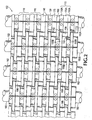
- FIG. 2 shows a section of the disc screen 102 in more detail.
- the disc screen 102 includes shafts 182 mounted to the sidewalls of frame 103 in a substantially parallel relationship.
- Each multi-diameter disc assembly 110 includes a small diameter spacer disc 130, a larger diameter intermediate disc 170, and an even larger diameter large disc 150.
- the large diameter disc 150 and an associated intermediate diameter disc 170 in the same disc assembly 110 is alternatively referred to as a compound disc 140 and in one embodiment is formed from a same unitary piece of rubber.
- the compound discs 140 are made from some material other than rubber, such as steel or a relatively hard resin.
- the compound discs 140 are formed from a different type of material than the spacer discs 130 and are mounted to the shafts 182 separately from the spacer discs 130.
- the multi-diameter disc assemblies 110 are aligned laterally on the shafts 182 so that the discs assemblies on adjacent shafts 182 overlap in a stair step manner as shown in FIG. 2 .
- the large diameter disc 150A is aligned laterally on the shaft 182A with the small diameter spacer disc 130B on shaft 182B.
- the intermediate discs 170A and 170B are aligned with each other on adjacent shafts 182A and 182B, respectively.
- the small diameter spacer disc 130A on shaft 182A is aligned with the large diameter disc 150B on adjacent shaft 182B.
- the disc assemblies 110 on adjacent shafts 182 maintain a substantially constant spacing.
- the space between adjacent intermediate diameter discs 170A and 170B form one of the inter-facial openings (IFOs) 108 that remain substantially constant during disc rotation.
- the IFOs 108 allow smaller sized objects 204 to drop through the disc screen 102 while some of the material 206 is transported up the disc screen 102.
- the spaces between the large diameter discs 150 and small diameter spacer discs 130 on adjacent shafts 182 form secondary slots 112.
- the secondary slots 112 also remain at a substantially constant size during disc rotation.
- openings 108 are around 2 inches x 2 inches but different dimensions cam be used for different material separation applications.
- the size of IFO openings 108 can vary according to the market for the fines material 204 which can differ according to region.
- the openings 108 may be larger, such as 3.25, 4.25, or 5.25 inches x 5 inches.
- the different discs 130, 150, and 170 function differently during the separation of material stream 200 and therefore exhibit different wear patterns.
- the large diameter discs 150 extend out above the intermediate and small diameter discs 170 and 130, respectively. Accordingly, the large diameter discs 150 take on much of the task of transporting material 200 up disc screen 102.
- the large diameter discs 150 also absorb much of the initial contact of the materials that are dropped and then fall back off the back end 106 of disc screen 102.
- the 3-dimensional containers 202 in material stream 200 are dropped onto the counter-clockwise rotating large discs 150 in FIG. 1 and tumble back over the back end 106 of disc screen 102 into chute 120.
- the large diameter discs also provide much of the up and down agitation of the MSW material 206 carried up the screen 102. Because of the large amount of contact with material 200, the larger discs 150 tend to have their cross sectional area reduced at a faster rate than the other smaller diameter discs 170 and 130.
- the intermediate discs form the IFOs 108 between adjacent shafts 182.
- the smaller diameter materials 202 fall through the IFOs 108 while being carried up screen 102.
- the intermediate discs 170 also serve to transport some of the materials 206 up the screen 102 and also contact, rotate, and cause some of materials 202 to fall off the back end 106 of screen 102.
- the intermediate diameter disc 170 contact less of the material stream 200 than the large diameter discs 150 and therefore their cross sectional area is reduced at a slower rate than the large discs 150.
- the spacer discs 130 have a smaller outside diameter than both the large discs 150 and the intermediate discs 170. Accordingly the spacer discs 130 come in much less contact with material stream 200 and transport relatively little of the material 206 up the screen 102.
- the primary function of the spacer discs 130 is to form the thin secondary slots 112 with the large discs 150 on adjacent shafts that are offset from the laterally adjacent IFOs 108. As explained above, the secondary slots 112 prevent relatively flat materials 206, such as paper and OCC, from dropping through the screen 102.
- the large discs 150 and intermediate discs 170 are made out of a softer rubber material to better grip, transport, and separate out different parts of MSW material stream 200.
- Rubber discs often grip MSW materials 206 better than a hard steel disc and therefore are more effective at separating the MSW material 200.
- One disadvantage is that the cross sectional area of the softer rubber discs may be reduced faster than harder discs.
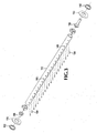
- FIGS. 3-5 show in more detail how the spacer discs 130 are separately interlocked together and attached to the shaft 182.
- the shaft 182 is made from a round elongated steel pipe. However, other triangular or square shapes shafts can also be used.
- the shaft 182 is connected to the opposite walls of the screen frame 103 ( FIG. 1 ) via gudeons 188, end plates 190 and cap plates 192.
- holes 186 are drilled through one side of the shaft 182 along substantially the entire shaft length.
- the holes 186 are positioned at the desired lateral positions on shaft 182 for locating the spacer discs 130.
- Key pins or spring pins 184 insert and compressibly attach into holes 186.
- dowel pins can be force fit or welded into the holes 186 or pins can be welded onto the outside surface of shaft 182.
- the spacer disc 130 comprises two sections 132A and 132B that are the exact same shape and therefore can both be made from the same mold.
- One of the sections 132A or 132B is turned upside down and attaches and interlocks with a corresponding end of the other section 132.
- the two sections 132A and 132B when attached together around shaft 182 form a symmetrical half of a triangular profile perimeter with three arched sides and three lobes 146A, 146B, and 146C.
- the two sections 132A and 132B each have an inside wall 135A and 135B, respectively, that are each sized and shaped to snugly press against and around half of the outside circumference of the shaft 182.
- the inside walls 135A and 135B each form a semi-circular shape that extends around half of the outside surface of the shaft 182.
- the two sections 132A and 132B each include an interlocking end 133 and a coupling end 143.
- the interlocking ends 133 include notches 138A and 138B that extend perpendicular into a first side of the sections 132A and 132B, respectively.
- Locking members 136A and 136B extend perpendicularly from a second side of the sections 132A and 132B above the notches 138A and 138B, respectively.
- sections 132A and/or 132B have a hole 134A and/or 134B formed in the inside wall 135A and/or 135B, respectively.
- the hole 134A and/or 134B is sized to slidingly receive one of the pins 184 that extend out of the shaft 182 as shown in FIG. 3 .
- One of the two sections 132A or 132B is attached to the shaft 182 such that the pin 184 slidingly inserts into hole 134A or 134B.
- the pin 184 prevents any rotational movement of the spacer disc 130 against the shaft 182 during operation as well as guaranteeing the location of the spacer disc 130 during maintenance replacement.
- section 132A or 132B that is not attached to pin 184 is rigidly interlocked with the other section 132 currently attached to shaft 182.
- section 132B has already been attached to the shaft 182, one of the pins 184 inserts into hole 134B, and the inside wall 135B presses and extends against half of the outside circumference of the shaft 182.
- Section 134A is flipped around 180 degrees from the position shown in FIG 5 .
- the section 132A is then pressed against the opposite half of the outside circumference of the shaft 182 but in a lateral position on shaft 182 adjacent to spacer section 134B.
- Spacer section 134A is then slid over the same lateral portion of shaft 182 where section 134B is located. While sliding over section 134B, the locking member 136A in section 132A 134A inserts into the notch 138 B formed in spacer section 132B. At the same time the locking member 136B in spacer section 132B slides into notch 138A formed in spacer section 132A. This interlocks the two sections 132A and 132B together at the interlocking end 133.
- the length of the shaft 182 and alignment of the multi-diameter disc assembly 110 may require attachment of single end discs 152 on the lateral ends of shafts 182.
- the end discs 152 may have the same shape as a single intermediate disc 170 or a single large diameter disc 150.
- the end discs 152 have two different sections 152A and 152B that attach together around the shaft 182 in a manner similar to the compound discs 140 as described in more detail below in FIGS. 6 and 7 .
- the spacer discs 130 are made out of a harder less gripping material than the compound discs 140.
- the spacer discs 130 can be made from a relatively hard fiberglass, polymer, nylon, or metal material, while the compound discs 140 are made out of a substantially softer rubber material.
- the spacer discs 130 can be made from a polyphthalamide (aka. PPA, High Performance Polyamide) which is a thermoplastic synthetic resin of the polyamide (nylon) family.
- the spacer discs 130 can not only be made from a harder material than the rubber compound discs 140 but can also be separately attached to the shaft 182. Thus, the compound discs 140 can be replaced without also having the replace the spacer discs 130. In other tri-disc designs, all three discs are formed from the same piece of rubber material. Thus, whenever the large and/or intermediate discs wear out, smaller discs also have to be replaced.
- the spacer discs 130 have the smallest outside diameter of the three discs 130, 150 and 170. Therefore, the spacer discs 130 will have the smallest material thickness between the outside surface of the shaft 182 and the smallest outside perimeter of the spacer disc 130 at locations 145.
- a minimum material thickness is necessary at locations 145 to keep the spacer disc 130 from tearing apart. Using materials that are harder and more wear resistant than rubber allow the spacer discs 130 at locations 145 to be much thinner. This allows the use of larger diameter shafts 182, resulting in larger center holes 172 ( FIG. 7C ) in the multi-diameter disc assemblies 110, and the use of less material in the multi-diameter disc assemblies 110. Thus, the costs of manufacturing and shipping the multi-diameter discs 110 are reduced.
- FIG. 6 shows an isolated view of one row of the disc screen 102 with the spacer discs 130 attached to the shaft 182 and the compound discs 140 shown in an exploded view.
- FIGS. 7A-7C show one embodiment of the compound discs 140 in more detail.
- the compound discs 140 are formed from a separate piece of material than the spacer discs 130. Forming the spacer discs 130 and compound discs 140 out of separate pieces of material allow the compound discs 140 to be separately replaced while the spacer discs 130 remain attached to the shafts 182.
- Each of the separate discs can have any variety of different shapes, sizes, and number of sides. Discs with different combinations of shapes, sizes, and number of sides can also be combined together. For example, a three sided triangular disc could be combined with a four sided square shaped disc in the same compound disc.
- the compound discs 140 include an upper section 140A and a lower section 140B that connect together around the shaft 182.
- the lower compound disc section 140B includes a lower large disc portion 150B that is integrally formed with a lower intermediate disc portion 170B from a same piece of material. Holes 164 extend through opposite ends of the lower intermediate disc portion 170B.
- An inside wall 169 of the lower compound disc section 140B has a semi-circular shape that snugly presses around half of the outside circumference of the shaft 182.
- the upper compound disc section 140A includes a large disc portion 150A and intermediate disc portion 170A that are both integrally formed together from the same piece of material.
- a U-bolt 160 is molded into the intermediate disc portion 170A and has opposite ends 161 that extend out from opposite ends 168A of the compound disc section 140A.
- a locating pin 162 is located at the center of the U-bolt 160 and extends out from an internal wall 167.
- the inside wall 167 of the upper compound disc section 140A also has a semi-circular shape that snugly attached around a second half of the circumference of the shaft 182.
- the locating pin 162 is inserted into one of the holes 198 in shaft 182 shown in FIG. 4 and prevents the compound disc 140 from sliding against the shaft 182.
- the inside surface 167 is pressed down against the upper half of the shaft 182 so that the opposite ends 161 of the U-bolt 160 extend on opposite sides of the shaft 182.
- the lower compound disc section 140B is pressed underneath a bottom end of the shaft 182 so that the ends 161 of U-bolt 160 insert into holes 164.
- the inside surface 169 of lower section 140B is up pressed against the lower outside surface of the shaft 182 while the opposite ends 168A and 168B of the upper and lower compound disc sections 140A and 140B, respectively press against each other.
- the opposite ends 168A of the upper section 140A have a flat surface 174A ( FIG. 7B ) and an inclined surface 175A.
- the opposite ends 168B of the lower section 140B also have a flat surface 174B and an upwardly inclined surface 175B oppositely opposed with surfaces 174A and 175A, respectively.
- the surfaces 174A and 174BA and surfaces 175A and 175B press against each other when the two sections 140A and 140B are pressed against the shaft 182.
- Each of the discs 130, 150, and 170 of the multi-diameter disc assembly 110 as shown above has three arched sides and a triangular profile.
- the multi-diameter discs 110 could have any number of arched sides and any number of different diameter discs.
- the multi-diameter disc assembly 110 could have four or five different discs with different diameters. Any of the different disc diameters can be separately formed from separate pieces of material with different hardness depending on screen wear and material gripping requirements.
- the intermediate discs 170 and large discs 150 could also be formed from separate pieces of material and separately attached to the shaft 182. For example, separate discs similar to the end discs 152 previously shown in FIG. 4 could be formed for each intermediate and large diameter disc 170 and 150, respectively. In this embodiment, each intermediate disc 170 and large diameter disc 150 would have a U-bolt 160 formed in an upper section that separately inserts into holes formed in a corresponding lower section.
- the spacer discs 130 could be made from a hardest material, since they do not provide the primary surface for material transport and agitation.
- the intermediate discs 170 could be made from a medium material hardness, since these discs provide an intermediate amount of material transport.
- the large diameter discs 150 could be formed of an even softer rubber material compared with discs 130 and 170, since the large diameter discs 150 need to provide most of the material transport and agitation.
- any combination of the discs 130, 150, and 170 may be formed from metal, rubber, polyphthalamid, polymer, or nylon material as described above. Any combination of the discs 130, 150, and 170 could also use the same interlocking system used by the spacer discs 130. Other attachment mechanisms could also be used.
- FIG. 8 shows a compound disc 230 similar to the compound disc 140 described above that includes an intermediate disc 234, a large disc 232, and upper and lower compound disc sections 230A and 230B that attach around the shaft 182 of the disc screen 102 shown in FIG. 1 .
- a channel 236 is formed into an outside perimeter surface of the large diameter disc 232.
- the channel 236 effectively forms a tread of two parallel ribs 238 that extend above and around opposite sides of the entire outside perimeter of the large diameter disc 232.
- This tread design can more effectively grip and transport certain types of material up disc screen 102 ( FIG. 1 ) for more efficient material separation.
- FIG. 9 shows a compound disc 250 with similar shapes as the compound disc 140 described above that includes intermediate disc 256, large disc 254, and upper and lower sections 250A and 250B that attach together around the shaft 182.
- the compound disc 250 has an alternative tread design that comprises slits or sipping 252 that are cut in diagonal directions with respect to the outside surface of large disc 254.
- the slits or sipping 252 may extend any distance from the outside surface toward the center of disc 254. In one example, the slits or sipping 252 may extend anywhere from around 0.1 inches to 0.5 inches into the surface of disc 254. In one embodiment, the slits 252 incline in a direction of disc rotation. This provides a serrated rough outside perimeter surface that improves the ability of the disc 254 to grip and carry materials up the disc screen 102.
- FIG. 10 shows a compound disc 260 having a shape similar to compound disc 140 that includes both an upper section 260A and a lower section 260B that attach together around the shaft 182.
- the compound disc 260 includes large diameter disc 264 and intermediate diameter disc 266.
- the compound disc 260 has a saw tooth shaped tread 262.
- the saw tooth treads 262 form notches 268 with oppositely inclining surfaces that form teeth 269.
- the teeth 269 provide sharply angled edges on the large diameter disc 264 that can hook, grab, and pull material up the disc screen 102 ( FIG. 1 ).
- FIG. 11 shows a compound disc 270 that includes both an upper section 270A and a lower section 270B that attach together around the shaft 182 of disc screen 102.
- the compound disc 270 includes large diameter disc 274 and intermediate diameter disc 276 that have shapes similar to the discs on the compound disc 140.
- the tread for compound disc 270 has rectangular shaped protuberances or knobs 278 and notched channels 272 having an arched convex shaped bottom surface 284 and oppositely inclining side walls 280.
- the knobs 278 and notched channels 272 provide multiple angled corners on the outside surface of the disc 274 that grip, carry, and separate the MSW materials.
- the different tread designs shown in FIGS. 8-11 in addition to the relatively slick tread described in FIGS. 3-7 can be used for different material separation applications or conditions.
- one of the tread design shown in FIGS. 1-7 may be better in warmer or drier material conditions.
- Another one of the tread designs in FIGS. 8-11 may be better in colder or wetter material conditions.
- the different tread designs can also provide different separation efficiency for different types of materials streams.
- the relatively slick outside surface of the multi-diameter disc assembly 110 shown in FIGS. 3-7 may be more efficient at separating out relatively flat fiber material, where one of the alternative tread designs shown in FIGS. 8-11 may provide more efficient material separation for 3-dimensional materials or slippery materials.
- the different tread designs as described above can be used at different locations of the same disc screen 102.
- one of the tread designs shown in FIGS. 8-11 may be used on the back end 106 of disc screen 102 in FIG. 1
- the flat surface of the disc assembly 110 shown in FIGS. 3-7 may be use in the middle or top end 104 of the disc screen 102 shown in FIG. 1 .
- the disc assemblies used in different modular sections of the same screen 102 as described below in FIG. 12 may each use different tread designs according to the particular separation application or stage.
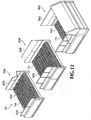
- FIG. 12 shows one embodiment of the separation system 100 that is formed from multiple different modular sections 300A, 300B, and 300C that are each separately attached together via bolts.
- Each modular screen section 300A, 300B, and 300C includes separate frames 302A, 302B, and 302C, respectively that support a separate screen section 102A, 102B, and 102C, respectively.
- each screen section 300 may have a separate motor that separately controls the rotation speed of the discs 110 in the particular screen section 300.
- Any number of modular separation system sections 300A, 300B, and 300C can be bolted together depending on the length of the screen needed for a particular material separation application.
- the modular screen sections 300 allow easier shipping, assembly, and replacement of separation systems 100. An exemplary embodiment can be summarized as follows.
- a material separation screen includes multiple shafts mounted on a frame.
- Multi-diameter disc assemblies are mounted on the shafts and are configured to rotate and separate out different types of materials from a material stream.
- the multi-diameter disc assemblies include spacer discs that separately interlock together around the shafts. Compound discs are separately attached to the shafts next to the spacer discs.
- the spacer discs are made from a harder material than the compound discs to reduce spacer disc wear and to reduce the amount of material needed for fabricating the multi-diameter disc assembly.
Landscapes
- Combined Means For Separation Of Solids (AREA)
Claims (11)
- Scheibe (130) für ein Materialtrennsieb, umfassend:einen ersten Abschnitt (132A), der dazu eingerichtet ist, um einen ersten Bereich einer Welle (182) angebracht zu sein, wobei der erste Abschnitt (132A) enthält:eine erste Seite des ersten Abschnitts (132A);eine zweite Seite des ersten Abschnitts (132A), die der ersten Seite des ersten Abschnitts (132A) gegenüber liegt, wobei die erste und die zweite Seite des ersten Abschnitts (132A) in der Axialrichtung der Welle (182) sind, wenn sie daran angebracht sind;eine erste Innenwand (135A) zwischen der ersten Seite des ersten Abschnitts (132A) und der zweiten Seite des ersten Abschnitts (132A), wobei die erste Innenwand (135A) dazu eingerichtet ist, gegen den ersten Bereich der Welle (182) zu drücken;ein erstes Verriegelungsende (133), wobei das erste Verriegelungsende (133) enthält:ein erstes Verriegelungsteil (136A), welches sich orthogonal zur ersten Seite des ersten Abschnitts (132A) erstreckt, wobei das erste Verriegelungsteil (136A) sich von der ersten Seite des ersten Abschnitts (132A) in Richtung der zweiten Seite des ersten Abschnitts (132A) erstreckt; undeine erste Aussparung (138A), wobei das erste Verriegelungsteil (136A) sich oberhalb der ersten Aussparung (138A) befindet; undein erstes Kopplungsende (143); undeinen zweiten Abschnitt (132B), der dazu eingerichtet ist, um einen zweiten Bereich der Welle (182) angebracht zu sein, wobei der erste und der zweite Abschnitt (132A; 132B) dazu eingerichtet sind, mehrere bogenförmige Seiten zu bilden, wenn sie zusammen um die Welle (182) angebracht sind, und wobei der zweite Abschnitt (132B) enthält:eine erste Seite des zweiten Abschnitts (132B);eine zweite Seite des zweiten Abschnitts (132B), die der ersten Seite des zweiten Abschnitts (132B) gegenüber liegt, wobei die erste und die zweite Seite des zweiten Abschnitts (132B) in der Axialrichtung der Welle (182) sind, wenn sie daran angebracht sind;eine zweite Innenwand (135B) zwischen der ersten Seite des zweiten Abschnitts (132B) und der zweiten Seite des zweiten Abschnitts (132B), wobei die zweite Innenwand (135B) dazu eingerichtet ist, gegen den zweiten Bereich der Welle (182) zu drücken;ein zweites Verriegelungsende (133), welches das erste Verriegelungsende (133) gleitend verriegelt, wobei das zweite Verriegelungsende (133) enthält:eine zweite Aussparung (138B), die dazu eingerichtet ist, das erste Verriegelungsteil (136A) des ersten Abschnitts (132A) zu empfangen; undein zweites Verriegelungsteil (136B), welches sich orthogonal zur ersten Seite des zweiten Abschnitts (132B) erstreckt, wobei das zweite Verriegelungsteil (136B) sich von der ersten Seite des zweiten Abschnitts (132B) in Richtung der zweiten Seite des zweiten Abschnitts (132B) erstreckt, und wobei die erste Aussparung (138A) des ersten Abschnitts (132A) dazu eingerichtet ist, das zweite Verriegelungsteil (136B) zu empfangen, und wobei das zweite Verriegelungsteil (136B) sich oberhalb der zweiten Aussparung (138B) befindet; undein zweites Kopplungsende (143), welches das erste Kopplungsende (143) des ersten Abschnitts (132A) koppelt, wobei der erste und der zweite Abschnitt dazu eingerichtet sind, mehrere bogenförmige Seiten zu bilden, wenn sie zusammen um die Welle angebracht sind.
- Scheibe (130) nach Anspruch 1, ferner enthaltend sich vollständig durch das erste und das zweite Kopplungsende (143) des ersten und des zweiten Abschnitts (132A; 132B) erstreckende Löcher (140A; 140B), die ausgerichtet sind, wenn das erste Verriegelungsende (133) des ersten Abschnitts (132A) gleitend mit dem zweiten Verriegelungsende (133) des zweiten Abschnitts (132B) verriegelt, wobei die ausgerichteten Löcher (140A; 140B) dazu eingerichtet sind, einen Bolzen zum Bolzenverbinden des ersten und des zweiten Abschnitts (132A; 132B) gemeinsam zu empfangen.
- Scheibe (130) nach Anspruch 1 oder 2, ferner enthaltend ein sich teilweise in die Innenwand (135A) des ersten Abschnitts (132A) und/oder eine Innenwand (135B) des zweiten Abschnitts (132B) erstreckendes Loch (134A; 134B), wobei das Loch (134A; 134B) dazu eingerichtet ist, einen Stift (184) zu empfangen, welcher sich aus der Welle (182) erstreckt.
- Scheibe (130) nach einem der obigen Ansprüche, wobei der erste Abschnitt (132A) und der zweite Abschnitt (132B) jeweils dieselbe Form aufweisen, wobei jeder eine symmetrische Hälfte der Scheibe (130) bildet.
- Scheibe (130) nach einem der vorherigen Ansprüche, enthaltend einen sich in und um eine äußere Umfangsoberfläche der Scheibe (130) erstreckenden Kanal.
- Scheibe (130) nach einem der vorherigen Ansprüche, enthaltend in und um eine äußere Umfangsoberfläche der Scheibe (130) gebildete Schlitze oder Schnitte (sipping).
- Scheibe (130) nach einem der vorherigen Ansprüche, enthaltend in und um eine äußere Umfangsoberfläche der Scheibe (130) gebildete Aussparungen, wobei die Aussparungen eine im Wesentlichen bogenförmige Grundfläche und gegenüberliegend geneigte Seitenwände aufweisen.
- Scheibe (130) nach einem der vorherigen Ansprüche, wobei das erste Kopplungsende (143) und das zweite Kopplungsende (143) Ende an Ende positioniert sind, wenn der erste Abschnitt (132A) und der zweite Abschnitt (132B) gleitend verriegelt sind.
- Materialverarbeitungssystem (100) umfassend:einen Rahmen (103);mehrere Wellen (182), die an dem Rahmen (103) montiert sind; undmehrere Scheiben (130), die in Übereinstimmung mit einem der obigen Ansprüche aufgebaut sind und die an den mehrere Wellen (182) derart montiert sind, dass sie das Materialtrennsieb bilden und die dazu eingerichtet sind, sich zu drehen und unterschiedliche Arten von Materialien aus einem Materialstrom zu trennen, während einige der Materialien über ein oberes Ende des Materialtrennsiebes transportiert werden.
- Materialverarbeitungssystem (100) nach Anspruch 9, wobei der Rahmen (103), die mehreren Wellen (182) und die mehreren Scheiben (130) in mehreren modularen Abschnitten (300A, 300B, 300C) gebildet sind, die jeweils dazu eingerichtet sind, separat gemeinsam angebracht zu sein, und/oder wobei der Materialstrom einen Hausmüll (Municipal Solid Waste), MSW, -Strom (200) umfasst.
- Materialverarbeitungssystem (100) nach Anspruch 10, wobei das Materialverarbeitungssystem (100) dazu eingerichtet ist, dass:ein erster Teil des MSW-Stroms, welcher Flaschen, Dosen, Krüge und andere dreidimensionale Objekte umfasst, von einem hinteren Ende des Materialtrennsiebes herunterfällt;ein zweiter Teil des MSW-Stroms, welcher größenmäßig relativ kleine Objekte umfasst, durch das Materialtrennsieb fällt; undein dritter Teil des MSW-Stroms, welcher Papier und Kartonfasermaterial umfasst, über ein oberes Ende des Materialtrennsiebes befördert wird.
Applications Claiming Priority (2)
| Application Number | Priority Date | Filing Date | Title |
|---|---|---|---|
| US12/616,521 US8424684B2 (en) | 2009-11-11 | 2009-11-11 | Multi-diameter disc assembly for material processing screen |
| EP10190774A EP2322288A3 (de) | 2009-11-11 | 2010-11-11 | Scheibenanordnung mit mehrfachem Durchmesser für ein Materialverarbeitungssieb |
Related Parent Applications (2)
| Application Number | Title | Priority Date | Filing Date |
|---|---|---|---|
| EP10190774A Division EP2322288A3 (de) | 2009-11-11 | 2010-11-11 | Scheibenanordnung mit mehrfachem Durchmesser für ein Materialverarbeitungssieb |
| EP10190774.9 Division | 2010-11-11 |
Publications (2)
| Publication Number | Publication Date |
|---|---|
| EP2656926A1 EP2656926A1 (de) | 2013-10-30 |
| EP2656926B1 true EP2656926B1 (de) | 2016-03-23 |
Family
ID=43536667
Family Applications (2)
| Application Number | Title | Priority Date | Filing Date |
|---|---|---|---|
| EP10190774A Withdrawn EP2322288A3 (de) | 2009-11-11 | 2010-11-11 | Scheibenanordnung mit mehrfachem Durchmesser für ein Materialverarbeitungssieb |
| EP13177752.6A Active EP2656926B1 (de) | 2009-11-11 | 2010-11-11 | Scheibe für ein Materialtrennsieb und Materialverarbeitungssystem mit einer Mehrzahl solcher Scheiben |
Family Applications Before (1)
| Application Number | Title | Priority Date | Filing Date |
|---|---|---|---|
| EP10190774A Withdrawn EP2322288A3 (de) | 2009-11-11 | 2010-11-11 | Scheibenanordnung mit mehrfachem Durchmesser für ein Materialverarbeitungssieb |
Country Status (5)
| Country | Link |
|---|---|
| US (1) | US8424684B2 (de) |
| EP (2) | EP2322288A3 (de) |
| CA (1) | CA2720525C (de) |
| DK (1) | DK2656926T3 (de) |
| ES (1) | ES2574427T3 (de) |
Families Citing this family (19)
| Publication number | Priority date | Publication date | Assignee | Title |
|---|---|---|---|---|
| CA2700962C (en) * | 2009-04-20 | 2013-12-17 | Jjg Ip Holdings, Llc | Method and apparatus for classification of recycled material |
| US8409063B2 (en) * | 2009-08-11 | 2013-04-02 | Goss International Americas, Inc. | Nip rollers with removable disks |
| US8991616B2 (en) * | 2012-11-21 | 2015-03-31 | Emerging Acquisitions, Llc | Material sorting discs with variable interfacial opening |
| DE102015101900A1 (de) * | 2015-02-10 | 2016-08-11 | Grimme Landmaschinenfabrik Gmbh & Co. Kg | Walzensegment für Trenn- und Reinigungsvorrichtungen in Hackfruchterntern und Verfahren zu dessen Herstellung |
| US20160318071A1 (en) * | 2015-04-28 | 2016-11-03 | Cp Manufacturing, Inc. | Helical Disc For Use In A Disc Screen |
| US9387516B1 (en) * | 2015-05-12 | 2016-07-12 | Cp Manufacturing, Inc. | Device and method to attach disc to shaft |
| DE102015119459A1 (de) * | 2015-11-11 | 2017-05-11 | Hydro Aluminium Rolled Products Gmbh | Verfahren und Siebvorrichtung zum Trennen von Aluminiumflachproduktstücken und nicht-metallischen Zwischenlagenstücken |
| US10307793B2 (en) | 2016-04-22 | 2019-06-04 | Emerging Acquisitions, Llc | Reusable material handling disc for recovery and separation of recyclable materials |
| US10111385B2 (en) | 2016-06-24 | 2018-10-30 | Jackrabbit | Nut harvester with separating disks |
| EP3263229B1 (de) * | 2016-06-27 | 2023-06-07 | Bollegraaf Patents and Brands B.V. | Scheibe für einen trennsiebförderer und trennsiebförderer mit solch einer scheibe |
| CN107457174A (zh) * | 2017-10-10 | 2017-12-12 | 天津百利阳光环保设备有限公司 | 一种筛分生活垃圾的圆盘筛 |
| US11432463B2 (en) | 2019-02-08 | 2022-09-06 | Jackrabbit, Inc. | Nut harvester with a removable assembly and a method of replacing a removable assembly of a nut harvester |
| CN113795337B (zh) * | 2019-05-10 | 2024-05-07 | 山特维克Srp股份有限公司 | 盘、间隔件和输送组件 |
| FI129310B (fi) * | 2019-07-12 | 2021-11-30 | Tana Oy | Seula |
| IT201900013791A1 (it) * | 2019-08-02 | 2021-02-02 | Ecostargreen S R L | Vaglio a dischi per la separazione di materiali solidi |
| NL2023991B1 (en) * | 2019-10-10 | 2021-06-17 | Bollegraaf Patents And Brands B V | Separating screen conveyor |
| CN110681565A (zh) * | 2019-11-14 | 2020-01-14 | 苏州鲁博环保设备有限公司 | 用于筛分不同块度和不同密度物料的设备 |
| IT202000014104A1 (it) * | 2020-06-12 | 2021-12-12 | Domenico Cappozzo | Vaglio a dischi per la separazione di materiali solidi |
| CN115069529A (zh) * | 2021-03-12 | 2022-09-20 | 北京都市绿源环保科技有限公司 | 一种用于生活可回收物垃圾分级的滚轴筛 |
Family Cites Families (17)
| Publication number | Priority date | Publication date | Assignee | Title |
|---|---|---|---|---|
| BE558516A (de) | ||||
| US1899737A (en) * | 1930-05-26 | 1933-02-28 | Charles B Ulrich | Resilient grizzly and screen |
| DE2751562A1 (de) | 1977-11-18 | 1979-05-23 | Buetfering Maschfab Geb | Rollenrost zum reinigen von feldfruechten, insbesondere zuckerrueben |
| US4901864A (en) * | 1988-08-16 | 1990-02-20 | International Paper Company | Grooved spacer for disc screen wood chip sorter |
| US5152402A (en) | 1991-04-08 | 1992-10-06 | Beloit Corporation | Flexibly embedded disc screen |
| US5586832A (en) * | 1995-05-22 | 1996-12-24 | Zylka; Karl-Heinz | Two piece interlocking shaft attachment |
| US5960964A (en) * | 1996-05-24 | 1999-10-05 | Bulk Handling, Inc. | Method and apparatus for sorting recycled material |
| EP0773070B2 (de) * | 1996-09-18 | 2002-07-24 | Machinefabriek Bollegraaf Appingedam B.V. | Sortierförderer zur Sortierung von Altpapier aus Altkarton |
| GB2357713B (en) * | 1997-03-26 | 2001-09-26 | Schleicher & Co Int Ag | Cutting mechanism of a document shredder |
| US6250478B1 (en) * | 1999-02-08 | 2001-06-26 | C P Manufacturing Inc. | Stepped disc screens of unequal inclination angles for conveying and grading recycling materials |
| US6460706B1 (en) * | 2001-06-15 | 2002-10-08 | Cp Manufacturing | Disc screen apparatus with air manifold |
| DE60219355T2 (de) * | 2001-10-02 | 2007-12-13 | Emerging Acquisitions, LLC, O'Fallon | Sieb |
| DE102004058898B4 (de) | 2004-12-07 | 2010-09-02 | Backers Maschinenbau Gmbh | Sieb und Siebelement hierfür |
| US20060226054A1 (en) * | 2005-03-31 | 2006-10-12 | Bishop Harry R Jr | Disc screen assembly |
| US20070138068A1 (en) * | 2005-12-18 | 2007-06-21 | Davis Robert M | Hinged disc for disc screen |
| US7549544B1 (en) * | 2006-11-22 | 2009-06-23 | Albert Ben Currey | Agitator and mechanical bucket for use therewith |
| US7578396B1 (en) * | 2007-10-16 | 2009-08-25 | Hustler Conveyor Company | Disc screen apparatus |
-
2009
- 2009-11-11 US US12/616,521 patent/US8424684B2/en active Active
-
2010
- 2010-11-09 CA CA2720525A patent/CA2720525C/en active Active
- 2010-11-11 EP EP10190774A patent/EP2322288A3/de not_active Withdrawn
- 2010-11-11 EP EP13177752.6A patent/EP2656926B1/de active Active
- 2010-11-11 DK DK13177752.6T patent/DK2656926T3/en active
- 2010-11-11 ES ES13177752.6T patent/ES2574427T3/es active Active
Also Published As
| Publication number | Publication date |
|---|---|
| EP2322288A3 (de) | 2013-03-06 |
| ES2574427T3 (es) | 2016-06-17 |
| US20110108467A1 (en) | 2011-05-12 |
| CA2720525A1 (en) | 2011-05-11 |
| EP2656926A1 (de) | 2013-10-30 |
| DK2656926T3 (en) | 2016-06-20 |
| EP2322288A2 (de) | 2011-05-18 |
| US8424684B2 (en) | 2013-04-23 |
| AU2010241324A1 (en) | 2011-05-26 |
| CA2720525C (en) | 2016-04-19 |
Similar Documents
| Publication | Publication Date | Title |
|---|---|---|
| CA2720525C (en) | Multi-diameter disc assembly for material processing screen | |
| WO2017184502A1 (en) | Reusable material handling disc assembly and method for recovery and separation of recyclable materials | |
| EP0849006B1 (de) | Verfahren und Vorrichtung zum Sortieren von wiederverwertbaren Materialien | |
| US7584856B2 (en) | Air separation of recyclable material | |
| CA2700962C (en) | Method and apparatus for classification of recycled material | |
| US9027762B2 (en) | Multi-disc assembly for disc screen | |
| US8800781B1 (en) | Disc for disc screen | |
| CA2436818C (en) | Roller screen and method for sorting materials by size | |
| CA2891223C (en) | Material sorting discs with variable interfacial opening | |
| EP3263229B1 (de) | Scheibe für einen trennsiebförderer und trennsiebförderer mit solch einer scheibe | |
| EP0885064B1 (de) | Vorrichtung zum behandeln von verbundelementen | |
| US8356715B2 (en) | Apparatus and method for sorting material | |
| ES2952560T3 (es) | Transportador de malla de separación | |
| US5482216A (en) | Method for reclaiming plastic which contains undesirable contaminants | |
| AU2021257989A1 (en) | Disc for use in disc screen | |
| US5377848A (en) | Roller screen for screening bulk material, especially wood chips | |
| US20200338595A1 (en) | Auger disc for use in disc screen | |
| EP1921027A1 (de) | Stützrolle | |
| JP2669792B2 (ja) | 選別機ロータ | |
| JPH0817955B2 (ja) | 廃棄物の篩分装置 | |
| AU7142100A (en) | A screen panel | |
| CA2461832A1 (en) | Separator apparatus |
Legal Events
| Date | Code | Title | Description |
|---|---|---|---|
| PUAI | Public reference made under article 153(3) epc to a published international application that has entered the european phase |
Free format text: ORIGINAL CODE: 0009012 |
|
| AC | Divisional application: reference to earlier application |
Ref document number: 2322288 Country of ref document: EP Kind code of ref document: P |
|
| AK | Designated contracting states |
Kind code of ref document: A1 Designated state(s): AL AT BE BG CH CY CZ DE DK EE ES FI FR GB GR HR HU IE IS IT LI LT LU LV MC MK MT NL NO PL PT RO RS SE SI SK SM TR |
|
| AX | Request for extension of the european patent |
Extension state: BA ME |
|
| 17P | Request for examination filed |
Effective date: 20140430 |
|
| RBV | Designated contracting states (corrected) |
Designated state(s): AL AT BE BG CH CY CZ DE DK EE ES FI FR GB GR HR HU IE IS IT LI LT LU LV MC MK MT NL NO PL PT RO RS SE SI SK SM TR |
|
| 17Q | First examination report despatched |
Effective date: 20140616 |
|
| GRAP | Despatch of communication of intention to grant a patent |
Free format text: ORIGINAL CODE: EPIDOSNIGR1 |
|
| INTG | Intention to grant announced |
Effective date: 20150918 |
|
| GRAS | Grant fee paid |
Free format text: ORIGINAL CODE: EPIDOSNIGR3 |
|
| GRAA | (expected) grant |
Free format text: ORIGINAL CODE: 0009210 |
|
| AC | Divisional application: reference to earlier application |
Ref document number: 2322288 Country of ref document: EP Kind code of ref document: P |
|
| AK | Designated contracting states |
Kind code of ref document: B1 Designated state(s): AL AT BE BG CH CY CZ DE DK EE ES FI FR GB GR HR HU IE IS IT LI LT LU LV MC MK MT NL NO PL PT RO RS SE SI SK SM TR |
|
| REG | Reference to a national code |
Ref country code: GB Ref legal event code: FG4D |
|
| REG | Reference to a national code |
Ref country code: CH Ref legal event code: EP |
|
| REG | Reference to a national code |
Ref country code: AT Ref legal event code: REF Ref document number: 782599 Country of ref document: AT Kind code of ref document: T Effective date: 20160415 |
|
| REG | Reference to a national code |
Ref country code: IE Ref legal event code: FG4D |
|
| REG | Reference to a national code |
Ref country code: DE Ref legal event code: R096 Ref document number: 602010031530 Country of ref document: DE |
|
| REG | Reference to a national code |
Ref country code: NL Ref legal event code: FP |
|
| REG | Reference to a national code |
Ref country code: ES Ref legal event code: FG2A Ref document number: 2574427 Country of ref document: ES Kind code of ref document: T3 Effective date: 20160617 |
|
| REG | Reference to a national code |
Ref country code: DK Ref legal event code: T3 Effective date: 20160614 |
|
| REG | Reference to a national code |
Ref country code: SE Ref legal event code: TRGR |
|
| REG | Reference to a national code |
Ref country code: LT Ref legal event code: MG4D |
|
| PG25 | Lapsed in a contracting state [announced via postgrant information from national office to epo] |
Ref country code: HR Free format text: LAPSE BECAUSE OF FAILURE TO SUBMIT A TRANSLATION OF THE DESCRIPTION OR TO PAY THE FEE WITHIN THE PRESCRIBED TIME-LIMIT Effective date: 20160323 Ref country code: FI Free format text: LAPSE BECAUSE OF FAILURE TO SUBMIT A TRANSLATION OF THE DESCRIPTION OR TO PAY THE FEE WITHIN THE PRESCRIBED TIME-LIMIT Effective date: 20160323 Ref country code: GR Free format text: LAPSE BECAUSE OF FAILURE TO SUBMIT A TRANSLATION OF THE DESCRIPTION OR TO PAY THE FEE WITHIN THE PRESCRIBED TIME-LIMIT Effective date: 20160624 Ref country code: NO Free format text: LAPSE BECAUSE OF FAILURE TO SUBMIT A TRANSLATION OF THE DESCRIPTION OR TO PAY THE FEE WITHIN THE PRESCRIBED TIME-LIMIT Effective date: 20160623 |
|
| REG | Reference to a national code |
Ref country code: AT Ref legal event code: MK05 Ref document number: 782599 Country of ref document: AT Kind code of ref document: T Effective date: 20160323 |
|
| PG25 | Lapsed in a contracting state [announced via postgrant information from national office to epo] |
Ref country code: LV Free format text: LAPSE BECAUSE OF FAILURE TO SUBMIT A TRANSLATION OF THE DESCRIPTION OR TO PAY THE FEE WITHIN THE PRESCRIBED TIME-LIMIT Effective date: 20160323 Ref country code: RS Free format text: LAPSE BECAUSE OF FAILURE TO SUBMIT A TRANSLATION OF THE DESCRIPTION OR TO PAY THE FEE WITHIN THE PRESCRIBED TIME-LIMIT Effective date: 20160323 Ref country code: LT Free format text: LAPSE BECAUSE OF FAILURE TO SUBMIT A TRANSLATION OF THE DESCRIPTION OR TO PAY THE FEE WITHIN THE PRESCRIBED TIME-LIMIT Effective date: 20160323 |
|
| PG25 | Lapsed in a contracting state [announced via postgrant information from national office to epo] |
Ref country code: PL Free format text: LAPSE BECAUSE OF FAILURE TO SUBMIT A TRANSLATION OF THE DESCRIPTION OR TO PAY THE FEE WITHIN THE PRESCRIBED TIME-LIMIT Effective date: 20160323 Ref country code: IS Free format text: LAPSE BECAUSE OF FAILURE TO SUBMIT A TRANSLATION OF THE DESCRIPTION OR TO PAY THE FEE WITHIN THE PRESCRIBED TIME-LIMIT Effective date: 20160723 Ref country code: EE Free format text: LAPSE BECAUSE OF FAILURE TO SUBMIT A TRANSLATION OF THE DESCRIPTION OR TO PAY THE FEE WITHIN THE PRESCRIBED TIME-LIMIT Effective date: 20160323 |
|
| PG25 | Lapsed in a contracting state [announced via postgrant information from national office to epo] |
Ref country code: SK Free format text: LAPSE BECAUSE OF FAILURE TO SUBMIT A TRANSLATION OF THE DESCRIPTION OR TO PAY THE FEE WITHIN THE PRESCRIBED TIME-LIMIT Effective date: 20160323 Ref country code: PT Free format text: LAPSE BECAUSE OF FAILURE TO SUBMIT A TRANSLATION OF THE DESCRIPTION OR TO PAY THE FEE WITHIN THE PRESCRIBED TIME-LIMIT Effective date: 20160725 Ref country code: CZ Free format text: LAPSE BECAUSE OF FAILURE TO SUBMIT A TRANSLATION OF THE DESCRIPTION OR TO PAY THE FEE WITHIN THE PRESCRIBED TIME-LIMIT Effective date: 20160323 Ref country code: SM Free format text: LAPSE BECAUSE OF FAILURE TO SUBMIT A TRANSLATION OF THE DESCRIPTION OR TO PAY THE FEE WITHIN THE PRESCRIBED TIME-LIMIT Effective date: 20160323 Ref country code: AT Free format text: LAPSE BECAUSE OF FAILURE TO SUBMIT A TRANSLATION OF THE DESCRIPTION OR TO PAY THE FEE WITHIN THE PRESCRIBED TIME-LIMIT Effective date: 20160323 Ref country code: RO Free format text: LAPSE BECAUSE OF FAILURE TO SUBMIT A TRANSLATION OF THE DESCRIPTION OR TO PAY THE FEE WITHIN THE PRESCRIBED TIME-LIMIT Effective date: 20160323 |
|
| REG | Reference to a national code |
Ref country code: DE Ref legal event code: R097 Ref document number: 602010031530 Country of ref document: DE |
|
| PLBE | No opposition filed within time limit |
Free format text: ORIGINAL CODE: 0009261 |
|
| STAA | Information on the status of an ep patent application or granted ep patent |
Free format text: STATUS: NO OPPOSITION FILED WITHIN TIME LIMIT |
|
| PG25 | Lapsed in a contracting state [announced via postgrant information from national office to epo] |
Ref country code: BG Free format text: LAPSE BECAUSE OF FAILURE TO SUBMIT A TRANSLATION OF THE DESCRIPTION OR TO PAY THE FEE WITHIN THE PRESCRIBED TIME-LIMIT Effective date: 20160623 Ref country code: BE Free format text: LAPSE BECAUSE OF NON-PAYMENT OF DUE FEES Effective date: 20161130 |
|
| 26N | No opposition filed |
Effective date: 20170102 |
|
| PG25 | Lapsed in a contracting state [announced via postgrant information from national office to epo] |
Ref country code: SI Free format text: LAPSE BECAUSE OF FAILURE TO SUBMIT A TRANSLATION OF THE DESCRIPTION OR TO PAY THE FEE WITHIN THE PRESCRIBED TIME-LIMIT Effective date: 20160323 |
|
| REG | Reference to a national code |
Ref country code: DE Ref legal event code: R119 Ref document number: 602010031530 Country of ref document: DE |
|
| REG | Reference to a national code |
Ref country code: DK Ref legal event code: EBP Effective date: 20161130 |
|
| REG | Reference to a national code |
Ref country code: CH Ref legal event code: PL |
|
| REG | Reference to a national code |
Ref country code: NL Ref legal event code: MM Effective date: 20161201 |
|
| GBPC | Gb: european patent ceased through non-payment of renewal fee |
Effective date: 20161111 |
|
| PG25 | Lapsed in a contracting state [announced via postgrant information from national office to epo] |
Ref country code: LI Free format text: LAPSE BECAUSE OF NON-PAYMENT OF DUE FEES Effective date: 20161130 Ref country code: CH Free format text: LAPSE BECAUSE OF NON-PAYMENT OF DUE FEES Effective date: 20161130 |
|
| REG | Reference to a national code |
Ref country code: IE Ref legal event code: MM4A |
|
| REG | Reference to a national code |
Ref country code: FR Ref legal event code: ST Effective date: 20170731 |
|
| PG25 | Lapsed in a contracting state [announced via postgrant information from national office to epo] |
Ref country code: NL Free format text: LAPSE BECAUSE OF NON-PAYMENT OF DUE FEES Effective date: 20161201 Ref country code: LU Free format text: LAPSE BECAUSE OF NON-PAYMENT OF DUE FEES Effective date: 20161130 |
|
| PG25 | Lapsed in a contracting state [announced via postgrant information from national office to epo] |
Ref country code: FR Free format text: LAPSE BECAUSE OF NON-PAYMENT OF DUE FEES Effective date: 20161130 Ref country code: IT Free format text: LAPSE BECAUSE OF NON-PAYMENT OF DUE FEES Effective date: 20161111 |
|
| PG25 | Lapsed in a contracting state [announced via postgrant information from national office to epo] |
Ref country code: GB Free format text: LAPSE BECAUSE OF NON-PAYMENT OF DUE FEES Effective date: 20161111 Ref country code: DE Free format text: LAPSE BECAUSE OF NON-PAYMENT OF DUE FEES Effective date: 20170601 Ref country code: DK Free format text: LAPSE BECAUSE OF NON-PAYMENT OF DUE FEES Effective date: 20161130 Ref country code: IE Free format text: LAPSE BECAUSE OF NON-PAYMENT OF DUE FEES Effective date: 20161111 |
|
| REG | Reference to a national code |
Ref country code: BE Ref legal event code: FP Effective date: 20160523 Ref country code: BE Ref legal event code: MM Effective date: 20161130 |
|
| PG25 | Lapsed in a contracting state [announced via postgrant information from national office to epo] |
Ref country code: CY Free format text: LAPSE BECAUSE OF FAILURE TO SUBMIT A TRANSLATION OF THE DESCRIPTION OR TO PAY THE FEE WITHIN THE PRESCRIBED TIME-LIMIT Effective date: 20160323 Ref country code: ES Free format text: LAPSE BECAUSE OF NON-PAYMENT OF DUE FEES Effective date: 20171112 Ref country code: HU Free format text: LAPSE BECAUSE OF FAILURE TO SUBMIT A TRANSLATION OF THE DESCRIPTION OR TO PAY THE FEE WITHIN THE PRESCRIBED TIME-LIMIT; INVALID AB INITIO Effective date: 20101111 |
|
| REG | Reference to a national code |
Ref country code: ES Ref legal event code: FD2A Effective date: 20180626 |
|
| PG25 | Lapsed in a contracting state [announced via postgrant information from national office to epo] |
Ref country code: MK Free format text: LAPSE BECAUSE OF FAILURE TO SUBMIT A TRANSLATION OF THE DESCRIPTION OR TO PAY THE FEE WITHIN THE PRESCRIBED TIME-LIMIT Effective date: 20160323 Ref country code: MC Free format text: LAPSE BECAUSE OF FAILURE TO SUBMIT A TRANSLATION OF THE DESCRIPTION OR TO PAY THE FEE WITHIN THE PRESCRIBED TIME-LIMIT Effective date: 20160323 |
|
| PG25 | Lapsed in a contracting state [announced via postgrant information from national office to epo] |
Ref country code: ES Free format text: LAPSE BECAUSE OF NON-PAYMENT OF DUE FEES Effective date: 20161112 |
|
| PG25 | Lapsed in a contracting state [announced via postgrant information from national office to epo] |
Ref country code: MT Free format text: LAPSE BECAUSE OF NON-PAYMENT OF DUE FEES Effective date: 20161111 |
|
| PG25 | Lapsed in a contracting state [announced via postgrant information from national office to epo] |
Ref country code: TR Free format text: LAPSE BECAUSE OF FAILURE TO SUBMIT A TRANSLATION OF THE DESCRIPTION OR TO PAY THE FEE WITHIN THE PRESCRIBED TIME-LIMIT Effective date: 20160323 Ref country code: AL Free format text: LAPSE BECAUSE OF FAILURE TO SUBMIT A TRANSLATION OF THE DESCRIPTION OR TO PAY THE FEE WITHIN THE PRESCRIBED TIME-LIMIT Effective date: 20160323 |
|
| P01 | Opt-out of the competence of the unified patent court (upc) registered |
Effective date: 20230522 |
|
| PGFP | Annual fee paid to national office [announced via postgrant information from national office to epo] |
Ref country code: SE Payment date: 20250910 Year of fee payment: 16 |