EP2656930A2 - Appareil de nettoyage et procédé de nettoyage pour des surfaces de nettoyage planes - Google Patents
Appareil de nettoyage et procédé de nettoyage pour des surfaces de nettoyage planes Download PDFInfo
- Publication number
- EP2656930A2 EP2656930A2 EP13163576.5A EP13163576A EP2656930A2 EP 2656930 A2 EP2656930 A2 EP 2656930A2 EP 13163576 A EP13163576 A EP 13163576A EP 2656930 A2 EP2656930 A2 EP 2656930A2
- Authority
- EP
- European Patent Office
- Prior art keywords
- cleaning
- cleaning head
- head
- vehicle
- brush
- Prior art date
- Legal status (The legal status is an assumption and is not a legal conclusion. Google has not performed a legal analysis and makes no representation as to the accuracy of the status listed.)
- Granted
Links
Images


Classifications
-
- A—HUMAN NECESSITIES
- A46—BRUSHWARE
- A46B—BRUSHES
- A46B5/00—Brush bodies; Handles integral with brushware
- A46B5/002—Brush bodies; Handles integral with brushware having articulations, joints or flexible portions
- A46B5/0033—Brush bodies; Handles integral with brushware having articulations, joints or flexible portions bending or stretching or collapsing
- A46B5/0041—Mechanical joint or hinge, made up of several components
-
- A—HUMAN NECESSITIES
- A46—BRUSHWARE
- A46B—BRUSHES
- A46B13/00—Brushes with driven brush bodies or carriers
- A46B13/001—Cylindrical or annular brush bodies
-
- A—HUMAN NECESSITIES
- A46—BRUSHWARE
- A46B—BRUSHES
- A46B13/00—Brushes with driven brush bodies or carriers
- A46B13/02—Brushes with driven brush bodies or carriers power-driven carriers
-
- B—PERFORMING OPERATIONS; TRANSPORTING
- B08—CLEANING
- B08B—CLEANING IN GENERAL; PREVENTION OF FOULING IN GENERAL
- B08B1/00—Cleaning by methods involving the use of tools
- B08B1/30—Cleaning by methods involving the use of tools by movement of cleaning members over a surface
- B08B1/32—Cleaning by methods involving the use of tools by movement of cleaning members over a surface using rotary cleaning members
- B08B1/34—Cleaning by methods involving the use of tools by movement of cleaning members over a surface using rotary cleaning members rotating about an axis parallel to the surface
-
- F—MECHANICAL ENGINEERING; LIGHTING; HEATING; WEAPONS; BLASTING
- F24—HEATING; RANGES; VENTILATING
- F24S—SOLAR HEAT COLLECTORS; SOLAR HEAT SYSTEMS
- F24S40/00—Safety or protection arrangements of solar heat collectors; Preventing malfunction of solar heat collectors
- F24S40/20—Cleaning; Removing snow
-
- Y—GENERAL TAGGING OF NEW TECHNOLOGICAL DEVELOPMENTS; GENERAL TAGGING OF CROSS-SECTIONAL TECHNOLOGIES SPANNING OVER SEVERAL SECTIONS OF THE IPC; TECHNICAL SUBJECTS COVERED BY FORMER USPC CROSS-REFERENCE ART COLLECTIONS [XRACs] AND DIGESTS
- Y02—TECHNOLOGIES OR APPLICATIONS FOR MITIGATION OR ADAPTATION AGAINST CLIMATE CHANGE
- Y02E—REDUCTION OF GREENHOUSE GAS [GHG] EMISSIONS, RELATED TO ENERGY GENERATION, TRANSMISSION OR DISTRIBUTION
- Y02E10/00—Energy generation through renewable energy sources
- Y02E10/40—Solar thermal energy, e.g. solar towers
Definitions
- the invention relates to the cleaning of planar, preferably inclined, cleaning surfaces, such as the surfaces of solar systems.
- these may be functional reasons, for example in the case of the surfaces of solar cells, which decrease with increasing pollution, in particular dusting, in their efficiency due to the lower amount of sunlight that reaches the solar cells.
- the cleaning head has a longitudinal extent in its longitudinal direction, which is at least as large as the width of the cleaning surface to be cleaned, measured transversely to the direction of progress, can by moving along of the cleaning head in the direction of progress cleaning the cleaning surface in a single pass.
- the cleaning head in its extension direction at least 1.5 times, better 2 times as long as the width of the carrier vehicle.
- the cleaning apparatus can also stand still, and during operation only the cantilever arm moves the cleaning head in the advancing direction along the cleaning surface, which is the distance control of the cleaning head Cleaning surface easier and reduces the risk of damage to cleaning surfaces, as this all occurring by an uneven surface and driving over the cleaning vehicle rolling movements of the boom and thus the cleaning head can be avoided.
- the brush may preferably be a cylindrical brush with an axial extent in the direction of extension of the cleaning head, or the cleaning head may comprise a plurality of cup brushes adjoining one another in its direction of extent.
- the cleaning head usually includes a frame in which the one or more cleaning brushes are added.
- the cleaning head cylinder brush may also be two or more adjoining cylinder brushes.
- the cleaning head preferably also comprises further elements, such as spray bars in front of and behind the cleaning head, viewed in the direction of progress, wherein the spray bars can have very different functions:
- cleaning liquid is applied to the cleaning surface for moistening the cleaning surface with one of the front spray bars, preferably the frontmost spray bar in the direction of travel.
- the second spray bar can spray cleaning fluid in the direction of and on the brushes.
- front spray bars can also be used for a pre-cleaning, for example a blow-off by means of compressed air and / or a dust extraction and / or there may be vibrators to subject the cleaning surface with vibrations, in particular ultrasonic vibrations, to the adhesive thereon To dissolve dirt.
- a pre-cleaning for example a blow-off by means of compressed air and / or a dust extraction and / or there may be vibrators to subject the cleaning surface with vibrations, in particular ultrasonic vibrations, to the adhesive thereon To dissolve dirt.
- a spray bar may be present, which either applies a fluid for cleaning the cleaning surface, and / or also applies compressed air to the cleaning surface for faster drying.
- Abziehlippe for mechanically removing the moisture from the cleaning surface may be mounted behind the brush. If compressed air nozzles are also available for drying, they are preferably located in the direction of travel behind the Abziehlippe.
- the cleaning head preferably also comprises a fastening traverse extending in the extension direction of the cleaning head, to which the coupling device for coupling the cleaning head to the extension arm is located, preferably in the middle of the traverse and thus also in the center of the cleaning head.
- This Traverse is hinged to the frame of the cleaning head, so that a tilting of the cleaning head z. B. against the direction of progress is possible, for example, if the cleaning head is pressed with too high contact force against the cleaning surface.
- the hinge axes are preferably selected extending in the extension direction of the cleaning head.
- the cleaning head is rotatable relative to the direction of extension of the arm part carrying it by means of automatic control, so that it can be used, for example in the work insert obliquely to the transverse direction, ie with the upper end of the cleaning head further forward than the rear end, and for all other necessary other positions , for example, transport positions, can be rotated accordingly.
- the cleaning head is pivotable about at least two, better three mutually perpendicular spatial directions and automatically adjusted during operation.
- the brushes preferably have flowstrips as cleaning elements, and are operated in the work insert at a speed of only 150 rpm to 200 rpm, more preferably between 170 rpm and 190 rpm.
- headlights present preferably waterproof encapsulated LED headlamps
- Preferably also in its emission direction by means of the control can be directed to the work area controlled, and preferably adjusted automatically and in dependence on the change in setting of boom and / or cleaning head with.
- a headlamp is preferably arranged on a stand, which is mounted, for example, on the bed of the carrier vehicle, and is preferably telescopic.
- sensors preferably non-contact sensors instead of sensing rollers or the like, are used, in particular ultrasonic sensors:
- sensors are located, for example, on the frame of the cleaning head and measure the distance to the cleaning surface.
- sensors can also be present on the carrier vehicle, which measure and monitor the lateral distance to the cleaning surface. All sensors are naturally coupled to the central control of the cleaning device. The sensors can also scan in the direction of progress prominent contours, such as the upper or lower end edge of the cleaning surface, and thus control the cleaning device and / or carrier vehicle along this contour.
- the cleaning liquid, with which the cleaning is carried out, is kept in storage containers, one or more of which are located on the loading surface of the carrier vehicle, in particular on the side opposite the attachment point of the delivery arm.
- this attachment point is mostly traversable in the transverse direction along a transverse offset rail with respect to the carrier vehicle.
- one of the reservoir is mounted in front of the front of the carrier vehicle as a front container.
- the storage tanks contain cleaning fluid or water, which may require both separately.
- the reservoirs are dimensioned and arranged so that all reservoirs are within the - viewed in the direction of travel - contour of the cleaning vehicle in order to generate here during maneuvering no additional damage risks.
- the cleaning liquid is usually discharged at a pressure of 3 bar to 4 bar from the nozzle, which has proven to be a good compromise between solvent power of the dirt and minimizing the risk of damage to the cleaning surfaces.
- the cleaning liquid can also be applied to the cleaning surface in a particularly low-tension state, which causes the cleaning liquid to roll off the cleaning surface and makes drying faster.
- an electric field generating E-field generator near the supply lines for cleaning liquid z. B. are arranged on the cleaning head, wherein the supply line for the cleaning fluid passes through the eye of a Tesla coil charged with power. Thereby, the surface tension of the liquid flowing therethrough is lowered.
- the cleaning liquid can be desalted or even completely demineralized before application, for example by means of an ion exchanger, in order to avoid streaks on the cleaning surface after drying.
- the cleaning liquid can be heated prior to application to the cleaning surface by means of a heating device in order to minimize the temperature difference between the sprayed-on cleaning liquid and the surface of the cleaning surface.
- a heating device preferably by means of a temperature sensor, which may be located on the cleaning head or at the free end of the cantilever arm, the surface temperature of the cleaning surface measured and reported to the controller, which controls the heating device in the direction of minimizing the temperature difference.
- the heating device may be operated either with the cooling system of the internal combustion engine of the host vehicle or be a separate, electric or hydraulic heating device.
- a locking device for the suspension of the vehicle may be present, in particular in the form of a lockable vertical axle support on one or both axles or in the form of a lockable additional torsional frame to the rolling movements of the vehicle to minimize.
- the central control of the cleaning device primarily controls the distance of the cleaning head from the cleaning surface, but can also automatically control inclination and optionally telescoping of the arm parts of the boom and / or the inclination of the cleaning head to the boom, and also the orientation of the headlights.
- the carrier vehicle stands still next to the cleaning surface or moves in the direction of progress along the cleaning surfaces, while the cleaning head - preferably obliquely to the transverse direction - extends across the entire width of the cleaning surface, so that in a single pass the entire surface can be cleaned ,
- a stationary during cleaning carrier vehicle offers in short in the direction of progress on surfaces, but also in long areas when the ground is very uneven and therefore the cleaning of the long in the progress direction cleaning surface sections only ever with a stationary carrier vehicle. If during work assignment the Carrier vehicle is moved, the rolling is preferably minimized, for example by blocking the suspension of the carrier vehicle.
- the cleaning head is supplied by the reservoirs located on the carrier vehicle with cleaning fluid and / or water.
- the carrier vehicle moves to the parked trailer, on which there are more filled storage containers.
- the storage container of the carrier vehicle can be refilled by pumping or the reservoir are - preferably exchanged between the trailer and reservoir - preferably using the boom as a crane.
- the storage rack is designed so that even the removal and placement of storage containers on the trailer is not hindered by the storage rack.
- the cleaning head can remain on the boom and by the boom in a transport position either side next to the carrier vehicle, aligned in the longitudinal direction, or behind the rear of the vehicle transverse, but then prominent on both sides over the width of the carrier vehicle.
- These transport positions are preferably programmed as fixed in the control of the cleaning device.
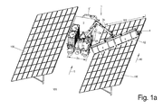
- FIG. 1 a is the cleaning task of the cleaning vehicle 2 with the cleaning device 1 attached thereto:
- slanted cleaning surfaces 100 are constructed in long rows in the form of solar panels, which fall to the driveways between the rows out on one side and have a width 102 which is significantly greater than the width 2 a of the cleaning vehicle . 2
- a cleaning vehicle 2 travels in the lanes in the direction of travel 10 between the cleaning surfaces 100 and thereby cleans those cleaning surfaces 100 next to the lane, which fall down to this lane and with the help of a cleaning head 4 , at least a rotating brush 5 , and whose extent is at least as large as the width 102 of the cleaning surface, so that in a single pass the entire width 102 of the cleaning surfaces 100 can be cleaned.
- This very wide cleaning head 4 is fixed in the middle on a cantilever arm which is fixed to the loading surface 2 b of the cleaning vehicle 2 and can be moved along offset rails 24 also in the transverse direction.
- the offset rails 24 preferably extend only from the center of the loading surface to the one outer side, in this case the right outer side, while along the left edge of the loading surface 2 b of the cleaning vehicle 2 in succession two reservoir 6 with cleaning liquid stand, from which the outlet nozzles 12th can be supplied with cleaning liquid at the spray bars 11 , which are located in front of and behind the brush 5 of the cleaning head 4 .
- the front container 6 ' may also have support legs 8 , as in FIG. 2 a indicated and in Figure 1 c to be able to park it safely after disconnection from the cleaning vehicle 2 on the ground.
- the suspension of the rear axle of the cleaning vehicle 2 can be deactivated by means of externally mounted between the wheel hub and the frame of the vehicle blocking devices 23rd
- Figure 1 c shows Figure 1 c in that a stand 18 additionally projects upwards from the loading surface 2 b, at the upper end of which a spotlight 17 for illuminating the working area is arranged on the cleaning surface 100 , since the cleaning of such solar panels preferably takes place at night.
- the cleaning head 4 is shown separately for a decoupled from the cantilever arm 3 separately next to it, and without the brush 5 , which is a cylindrical cylindrical brush 5 in the rotating state, which is around a Rotates rotation axis, which is parallel to the extension direction 4 'of the cleaning head 4 .
- the frame 14 mainly consists of a U-shaped fork, between the free ends of the brush 5 , not shown here is inserted and can be driven by means of the motor 14 attached to the frame 20 rotating.
- the parallel front and extending behind the frame spray bars 11 are arranged with outlet openings 12, can be applied over the optional cleaning liquid, clean water, compressed air or the like, depending on the orientation of the outlet nozzles 12 directly onto the cleaning surface 100, or directed against the brush 5 .
- two spray strips 11 are arranged in quick succession on the front side of the cleaning head 10 in the direction of travel, of which the first liquid in the direction of travel 10 is directed directly against the cleaning surface 100 , to soften the dirt adhering there, while the second spray bar 11 liquid on the Brush 5 spray to keep it always wet enough.
- FIG. 1b Furthermore, in the direction of travel behind, behind the last spray bar 11 , a Abziehlippe 13 is shown, with the remaining moisture on the cleaning surface 100 can be deducted. Not least because of this - as in FIG. 1 a visible - the cleaning head 4 is not exactly perpendicular to the direction of travel, the direction of progress 10 of the cleaning process, provided, but obliquely, so that the upper end of the cleaning head 4 in the direction of travel 10 continues to run forward.
- FIG. 1a also shows, the cleaning head 4 in its extension direction 4 'one behind the other two aligned cylindrical Brushes 5 , or even a single, which extends over the entire length, as in the variant of Figures 1 b and 1 c shown.
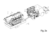
- FIGS. 2a and 3 show different transport conditions of the cleaning vehicle 2:
- FIG. 2a pulls the cleaning vehicle 2 a trailer 22 , on which there are more reservoir 6 with cleaning fluid. During cleaning, this trailer 22 is set aside, however, the cleaning vehicle 2 can refuel from its reservoirs 6 standing on the back of the cleaning vehicle 2 reservoir and / or the front container 6 ' .
- a storage frame 21 which extends over the height of the storage container 6 out and represents a kind of bridge to it, placing the cleaning head 4, which is then disconnected from the jib 3 with its direction of extension 4 'in the direction 10, ie in Longitudinal direction of the trailer 22 is on this and can be transported in this way by the combination of vehicle 2 and trailer 22 does not exceed the permitted width and height for road driving.
- the storage rack 21 is preferably constructed so that even when lying on cleaning head 4, the reservoir 6 located underneath at least refilled, better even from the trailer 22 can be removed.
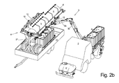
- FIG. 2b shows how the cleaning vehicle 2 in addition to the uncoupled trailer 22 moves to a distance such that it can pass by means of a cantilever arm 3 the cleaning head 4 on the tray frame 21 of the trailer 22, and then disconnect from the arm.
- cleaning heads 4 may be.
- the cantilever arm 3 is also directed in the vehicle center extending from its attachment point on the back of the cleaning vehicle 2 in the direction of travel 10 to the rear and still carries the cleaning head 4 , which is now in the transverse direction, preferably at right angles to the direction of travel 10 , ie the longitudinal direction of the cleaning vehicle 2 , located behind the rear of the cleaning vehicle and accordingly protrudes significantly on both sides over the contour 9 of the cleaning vehicle 2 .
Landscapes
- Engineering & Computer Science (AREA)
- Mechanical Engineering (AREA)
- Physics & Mathematics (AREA)
- Life Sciences & Earth Sciences (AREA)
- Sustainable Development (AREA)
- Sustainable Energy (AREA)
- Thermal Sciences (AREA)
- Chemical & Material Sciences (AREA)
- Combustion & Propulsion (AREA)
- General Engineering & Computer Science (AREA)
- Cleaning In General (AREA)
Applications Claiming Priority (1)
| Application Number | Priority Date | Filing Date | Title |
|---|---|---|---|
| DE102012103574.1A DE102012103574B4 (de) | 2012-04-24 | 2012-04-24 | Reinigungsgerät und Reinigungsverfahren für ebene Reinigungsflächen |
Publications (3)
| Publication Number | Publication Date |
|---|---|
| EP2656930A2 true EP2656930A2 (fr) | 2013-10-30 |
| EP2656930A3 EP2656930A3 (fr) | 2014-02-26 |
| EP2656930B1 EP2656930B1 (fr) | 2019-03-27 |
Family
ID=48095690
Family Applications (1)
| Application Number | Title | Priority Date | Filing Date |
|---|---|---|---|
| EP13163576.5A Not-in-force EP2656930B1 (fr) | 2012-04-24 | 2013-04-12 | Appareil de nettoyage et procédé de nettoyage pour des surfaces de nettoyage planes |
Country Status (3)
| Country | Link |
|---|---|
| EP (1) | EP2656930B1 (fr) |
| DE (1) | DE102012103574B4 (fr) |
| ES (1) | ES2729556T3 (fr) |
Cited By (10)
| Publication number | Priority date | Publication date | Assignee | Title |
|---|---|---|---|---|
| CN104209299A (zh) * | 2014-08-28 | 2014-12-17 | 金丹 | 太阳能电站综合保洁装置 |
| CN104722540A (zh) * | 2015-04-15 | 2015-06-24 | 上海电机学院 | 一种太阳能板清洗装置 |
| CN105921474A (zh) * | 2016-07-01 | 2016-09-07 | 北京旭海睿能源科技有限公司 | 太阳能电池板智能运营维护车及清洗方法 |
| CN109420629A (zh) * | 2017-08-21 | 2019-03-05 | 浙江大学 | 倾斜面上的作业装置及其应用在光伏电站的清扫方法 |
| CN110871181A (zh) * | 2019-11-16 | 2020-03-10 | 冀振兰 | 一种广告牌清洁车 |
| CN113539904A (zh) * | 2021-07-19 | 2021-10-22 | 西安奕斯伟硅片技术有限公司 | 一种双面研磨中下定盘沟槽的清洁装置、系统以及方法 |
| CN113560295A (zh) * | 2021-08-11 | 2021-10-29 | 厦门威迪思汽车设计服务有限公司 | 集装箱清洗装置及其清洗方法 |
| CN119140469A (zh) * | 2024-11-19 | 2024-12-17 | 江苏东禾特种设备科技有限公司 | 一种桥门式起重机轨道清洁装置 |
| WO2025147729A1 (fr) | 2024-01-09 | 2025-07-17 | Teufl Gmbh | Appareil de lutte contre les mauvaises herbes |
| NL2037963B1 (en) * | 2024-06-17 | 2026-01-12 | Future Cleaning Tech B V | Adaptive surface sanitation system and method |
Families Citing this family (3)
| Publication number | Priority date | Publication date | Assignee | Title |
|---|---|---|---|---|
| DE202014105844U1 (de) * | 2014-12-04 | 2016-03-07 | Franz Ehleuter | Reinigungsvorrichtung und Hebebühne mit einer derartigen Reinigungsvorrichtung |
| CN108954869B (zh) * | 2018-06-06 | 2020-08-07 | 东阳市阳涛电子科技有限公司 | 一种可自动清理的太阳能热水器 |
| US11638939B2 (en) * | 2018-11-27 | 2023-05-02 | Steam Tech, Llc | Mobile panel cleaner |
Family Cites Families (8)
| Publication number | Priority date | Publication date | Assignee | Title |
|---|---|---|---|---|
| DE69001562D1 (de) | 1989-02-15 | 1993-06-17 | Valk & De Groot Bv | Waschfahrzeug. |
| ES2316317A1 (es) * | 2008-08-08 | 2009-04-01 | Ingenieria Y Marketing, S.A. | Metodo para la limpieza de espejos con seccion parabolica de una planta termosolar y aparato para la ejecucion del metodo. |
| EP2442048A4 (fr) | 2009-06-12 | 2013-12-25 | Abengoa Solar New Tech Sa | Véhicule et procédé de nettoyage pour collecteurs solaires de type cylindro-parabolique |
| DE102009040778A1 (de) * | 2009-09-09 | 2011-03-10 | MULAG FAHRZEUGWERK Heinz Wössner GmbH & Co. KG | Reinigungsgerät für Thermosolarkraftwerke |
| DE102010011385A1 (de) * | 2010-03-12 | 2011-09-15 | Flagsol Gmbh | Parabolspiegelwaschfahrzeug |
| DE202011051073U1 (de) | 2011-03-18 | 2011-12-28 | Marcus Brand | Reinigungsvorrichtung für Solarmodule |
| DE202011105493U1 (de) | 2011-09-09 | 2011-12-13 | Franz Ehleuter | Vorrichtung zum Reinigen von glatten Flächen |
| DE202011052050U1 (de) | 2011-11-22 | 2012-01-27 | Patrick Kathöfer | Einrichtung zur Reinigung von Oberflächen |
-
2012
- 2012-04-24 DE DE102012103574.1A patent/DE102012103574B4/de not_active Expired - Fee Related
-
2013
- 2013-04-12 EP EP13163576.5A patent/EP2656930B1/fr not_active Not-in-force
- 2013-04-12 ES ES13163576T patent/ES2729556T3/es active Active
Non-Patent Citations (1)
| Title |
|---|
| None |
Cited By (13)
| Publication number | Priority date | Publication date | Assignee | Title |
|---|---|---|---|---|
| CN104209299A (zh) * | 2014-08-28 | 2014-12-17 | 金丹 | 太阳能电站综合保洁装置 |
| CN104209299B (zh) * | 2014-08-28 | 2018-12-14 | 金丹 | 太阳能电站综合保洁装置 |
| CN104722540A (zh) * | 2015-04-15 | 2015-06-24 | 上海电机学院 | 一种太阳能板清洗装置 |
| CN105921474A (zh) * | 2016-07-01 | 2016-09-07 | 北京旭海睿能源科技有限公司 | 太阳能电池板智能运营维护车及清洗方法 |
| CN109420629B (zh) * | 2017-08-21 | 2020-05-22 | 浙江大学 | 倾斜面上的作业装置及其应用在光伏电站的清扫方法 |
| CN109420629A (zh) * | 2017-08-21 | 2019-03-05 | 浙江大学 | 倾斜面上的作业装置及其应用在光伏电站的清扫方法 |
| CN110871181A (zh) * | 2019-11-16 | 2020-03-10 | 冀振兰 | 一种广告牌清洁车 |
| CN110871181B (zh) * | 2019-11-16 | 2021-11-02 | 合肥森岑汽车用品有限公司 | 一种广告牌清洁车 |
| CN113539904A (zh) * | 2021-07-19 | 2021-10-22 | 西安奕斯伟硅片技术有限公司 | 一种双面研磨中下定盘沟槽的清洁装置、系统以及方法 |
| CN113560295A (zh) * | 2021-08-11 | 2021-10-29 | 厦门威迪思汽车设计服务有限公司 | 集装箱清洗装置及其清洗方法 |
| WO2025147729A1 (fr) | 2024-01-09 | 2025-07-17 | Teufl Gmbh | Appareil de lutte contre les mauvaises herbes |
| NL2037963B1 (en) * | 2024-06-17 | 2026-01-12 | Future Cleaning Tech B V | Adaptive surface sanitation system and method |
| CN119140469A (zh) * | 2024-11-19 | 2024-12-17 | 江苏东禾特种设备科技有限公司 | 一种桥门式起重机轨道清洁装置 |
Also Published As
| Publication number | Publication date |
|---|---|
| EP2656930B1 (fr) | 2019-03-27 |
| DE102012103574B4 (de) | 2018-03-29 |
| ES2729556T3 (es) | 2019-11-04 |
| EP2656930A3 (fr) | 2014-02-26 |
| DE102012103574A1 (de) | 2013-10-24 |
Similar Documents
| Publication | Publication Date | Title |
|---|---|---|
| EP2656930B1 (fr) | Appareil de nettoyage et procédé de nettoyage pour des surfaces de nettoyage planes | |
| EP2295158B1 (fr) | Appareil de nettoyage pour centrales thermosolaires | |
| DE19963742C2 (de) | Fahrzeugwaschanlage | |
| DE102016224098B4 (de) | Omnidirektional mobile Kraftfahrzeug-Transportplattform, zugehörige Kraftfahrzeug-Versorgungsstation und Parksystem | |
| EP2581687A1 (fr) | Dispositif et véhicule de traitement de surfaces planes | |
| EP1837442B2 (fr) | Train de finisseuses | |
| WO2013068575A2 (fr) | Machine de nettoyage pour fenêtres, éléments de façades, modules solaires et éléments de surface similaires à surface plane | |
| DE102009006146A1 (de) | Fahrbare HD-Reinigungsmaschine für Outdoor-Kunststoffböden, und deren Anwendung | |
| DE202011001292U1 (de) | Tunnelwaschfahrzeug | |
| DE102013219444A1 (de) | Ladeeinrichtung zum induktiven Laden | |
| WO2011110670A1 (fr) | Véhicule de nettoyage pour miroir parabolique | |
| DE19910790C1 (de) | Fahrzeugwaschanlage zum Waschen von Kraftfahrzeugen | |
| WO2019038188A1 (fr) | Plateforme à roues déplaçable de manière omnidirectionnelle dotée d'un dispositif de travail | |
| DE102017011146A1 (de) | Gummiradwalze zur Verdichtung eines Bodens und Verfahren zur Steuerung einer Berieselungsanlage einer Gummiradwalze | |
| DE2257607A1 (de) | Verfahren und vorrichtung zur reinigung von oberflaechen | |
| DE3928914A1 (de) | Schneeraeumvorrichtung | |
| CH598422A5 (en) | Mobile tunnel cleaning and spraying machine | |
| DE19716741C2 (de) | Vorrichtung zum Reinigen der Flächen einer Glaskonstruktion | |
| EP0447601A1 (fr) | Dispositif de nettoyage de marquages routiers | |
| DE3911731C1 (fr) | ||
| DE102011054610A1 (de) | Verfahren und Vorrichtung zum Aufbringen von Frostschutzmittel auf einen Fahrdraht sowie mit einer solchen Vorrichtung ausgestattetes, elektrisch betriebenes Fahrzeug | |
| EP3738684B1 (fr) | Dispositif de traitement des surfaces lisses, en particulier de la surface des installations photovoltaïques et solaires | |
| DE102009023207A1 (de) | Straßenfertiger und Verfahren zum Verändern der Arbeitsbreite eines Straßenfertigers | |
| DE20020793U1 (de) | Vorrichtung zum Reinigen von Behältern, insbesondere zur Innenreinigung von Mülltonnen | |
| DE202020100496U1 (de) | Vorrichtung zum Behandeln einer Oberfläche mit Trockeneis |
Legal Events
| Date | Code | Title | Description |
|---|---|---|---|
| PUAI | Public reference made under article 153(3) epc to a published international application that has entered the european phase |
Free format text: ORIGINAL CODE: 0009012 |
|
| AK | Designated contracting states |
Kind code of ref document: A2 Designated state(s): AL AT BE BG CH CY CZ DE DK EE ES FI FR GB GR HR HU IE IS IT LI LT LU LV MC MK MT NL NO PL PT RO RS SE SI SK SM TR |
|
| AX | Request for extension of the european patent |
Extension state: BA ME |
|
| PUAL | Search report despatched |
Free format text: ORIGINAL CODE: 0009013 |
|
| AK | Designated contracting states |
Kind code of ref document: A3 Designated state(s): AL AT BE BG CH CY CZ DE DK EE ES FI FR GB GR HR HU IE IS IT LI LT LU LV MC MK MT NL NO PL PT RO RS SE SI SK SM TR |
|
| AX | Request for extension of the european patent |
Extension state: BA ME |
|
| RIC1 | Information provided on ipc code assigned before grant |
Ipc: F24J 2/46 20060101ALI20140123BHEP Ipc: B08B 1/04 20060101AFI20140123BHEP |
|
| 17P | Request for examination filed |
Effective date: 20141212 |
|
| RBV | Designated contracting states (corrected) |
Designated state(s): AL AT BE BG CH CY CZ DE DK EE ES FI FR GB GR HR HU IE IS IT LI LT LU LV MC MK MT NL NO PL PT RO RS SE SI SK SM TR |
|
| R17P | Request for examination filed (corrected) |
Effective date: 20140826 |
|
| RIC1 | Information provided on ipc code assigned before grant |
Ipc: B08B 1/04 20060101AFI20150216BHEP Ipc: F24J 2/46 20060101ALI20150216BHEP |
|
| STAA | Information on the status of an ep patent application or granted ep patent |
Free format text: STATUS: EXAMINATION IS IN PROGRESS |
|
| RIC1 | Information provided on ipc code assigned before grant |
Ipc: A46B 5/00 20060101AFI20170228BHEP Ipc: B08B 1/04 20060101ALI20170228BHEP Ipc: F24J 2/46 20060101ALI20170228BHEP Ipc: A46B 13/00 20060101ALI20170228BHEP Ipc: A46B 13/02 20060101ALI20170228BHEP |
|
| 17Q | First examination report despatched |
Effective date: 20170330 |
|
| REG | Reference to a national code |
Ref country code: DE Ref legal event code: R079 Ref document number: 502013012473 Country of ref document: DE Free format text: PREVIOUS MAIN CLASS: B08B0001040000 Ipc: A46B0005000000 |
|
| GRAP | Despatch of communication of intention to grant a patent |
Free format text: ORIGINAL CODE: EPIDOSNIGR1 |
|
| STAA | Information on the status of an ep patent application or granted ep patent |
Free format text: STATUS: GRANT OF PATENT IS INTENDED |
|
| RIC1 | Information provided on ipc code assigned before grant |
Ipc: A46B 5/00 20060101AFI20180823BHEP Ipc: A46B 13/02 20060101ALI20180823BHEP Ipc: F24S 40/20 20180101ALI20180823BHEP Ipc: B08B 1/04 20060101ALI20180823BHEP Ipc: A46B 13/00 20060101ALI20180823BHEP |
|
| INTG | Intention to grant announced |
Effective date: 20180924 |
|
| GRAJ | Information related to disapproval of communication of intention to grant by the applicant or resumption of examination proceedings by the epo deleted |
Free format text: ORIGINAL CODE: EPIDOSDIGR1 |
|
| STAA | Information on the status of an ep patent application or granted ep patent |
Free format text: STATUS: EXAMINATION IS IN PROGRESS |
|
| GRAS | Grant fee paid |
Free format text: ORIGINAL CODE: EPIDOSNIGR3 |
|
| STAA | Information on the status of an ep patent application or granted ep patent |
Free format text: STATUS: GRANT OF PATENT IS INTENDED |
|
| GRAP | Despatch of communication of intention to grant a patent |
Free format text: ORIGINAL CODE: EPIDOSNIGR1 |
|
| GRAA | (expected) grant |
Free format text: ORIGINAL CODE: 0009210 |
|
| STAA | Information on the status of an ep patent application or granted ep patent |
Free format text: STATUS: THE PATENT HAS BEEN GRANTED |
|
| INTC | Intention to grant announced (deleted) | ||
| INTG | Intention to grant announced |
Effective date: 20190207 |
|
| AK | Designated contracting states |
Kind code of ref document: B1 Designated state(s): AL AT BE BG CH CY CZ DE DK EE ES FI FR GB GR HR HU IE IS IT LI LT LU LV MC MK MT NL NO PL PT RO RS SE SI SK SM TR |
|
| REG | Reference to a national code |
Ref country code: GB Ref legal event code: FG4D Free format text: NOT ENGLISH |
|
| REG | Reference to a national code |
Ref country code: CH Ref legal event code: EP |
|
| REG | Reference to a national code |
Ref country code: AT Ref legal event code: REF Ref document number: 1111964 Country of ref document: AT Kind code of ref document: T Effective date: 20190415 |
|
| REG | Reference to a national code |
Ref country code: IE Ref legal event code: FG4D Free format text: LANGUAGE OF EP DOCUMENT: GERMAN |
|
| REG | Reference to a national code |
Ref country code: DE Ref legal event code: R096 Ref document number: 502013012473 Country of ref document: DE |
|
| PG25 | Lapsed in a contracting state [announced via postgrant information from national office to epo] |
Ref country code: SE Free format text: LAPSE BECAUSE OF FAILURE TO SUBMIT A TRANSLATION OF THE DESCRIPTION OR TO PAY THE FEE WITHIN THE PRESCRIBED TIME-LIMIT Effective date: 20190327 Ref country code: NO Free format text: LAPSE BECAUSE OF FAILURE TO SUBMIT A TRANSLATION OF THE DESCRIPTION OR TO PAY THE FEE WITHIN THE PRESCRIBED TIME-LIMIT Effective date: 20190627 Ref country code: FI Free format text: LAPSE BECAUSE OF FAILURE TO SUBMIT A TRANSLATION OF THE DESCRIPTION OR TO PAY THE FEE WITHIN THE PRESCRIBED TIME-LIMIT Effective date: 20190327 Ref country code: LT Free format text: LAPSE BECAUSE OF FAILURE TO SUBMIT A TRANSLATION OF THE DESCRIPTION OR TO PAY THE FEE WITHIN THE PRESCRIBED TIME-LIMIT Effective date: 20190327 |
|
| PGFP | Annual fee paid to national office [announced via postgrant information from national office to epo] |
Ref country code: ES Payment date: 20190520 Year of fee payment: 7 |
|
| REG | Reference to a national code |
Ref country code: NL Ref legal event code: MP Effective date: 20190327 |
|
| PG25 | Lapsed in a contracting state [announced via postgrant information from national office to epo] |
Ref country code: GR Free format text: LAPSE BECAUSE OF FAILURE TO SUBMIT A TRANSLATION OF THE DESCRIPTION OR TO PAY THE FEE WITHIN THE PRESCRIBED TIME-LIMIT Effective date: 20190628 Ref country code: BG Free format text: LAPSE BECAUSE OF FAILURE TO SUBMIT A TRANSLATION OF THE DESCRIPTION OR TO PAY THE FEE WITHIN THE PRESCRIBED TIME-LIMIT Effective date: 20190627 Ref country code: HR Free format text: LAPSE BECAUSE OF FAILURE TO SUBMIT A TRANSLATION OF THE DESCRIPTION OR TO PAY THE FEE WITHIN THE PRESCRIBED TIME-LIMIT Effective date: 20190327 Ref country code: LV Free format text: LAPSE BECAUSE OF FAILURE TO SUBMIT A TRANSLATION OF THE DESCRIPTION OR TO PAY THE FEE WITHIN THE PRESCRIBED TIME-LIMIT Effective date: 20190327 Ref country code: NL Free format text: LAPSE BECAUSE OF FAILURE TO SUBMIT A TRANSLATION OF THE DESCRIPTION OR TO PAY THE FEE WITHIN THE PRESCRIBED TIME-LIMIT Effective date: 20190327 Ref country code: RS Free format text: LAPSE BECAUSE OF FAILURE TO SUBMIT A TRANSLATION OF THE DESCRIPTION OR TO PAY THE FEE WITHIN THE PRESCRIBED TIME-LIMIT Effective date: 20190327 |
|
| PGFP | Annual fee paid to national office [announced via postgrant information from national office to epo] |
Ref country code: FR Payment date: 20190521 Year of fee payment: 7 |
|
| PG25 | Lapsed in a contracting state [announced via postgrant information from national office to epo] |
Ref country code: SK Free format text: LAPSE BECAUSE OF FAILURE TO SUBMIT A TRANSLATION OF THE DESCRIPTION OR TO PAY THE FEE WITHIN THE PRESCRIBED TIME-LIMIT Effective date: 20190327 Ref country code: EE Free format text: LAPSE BECAUSE OF FAILURE TO SUBMIT A TRANSLATION OF THE DESCRIPTION OR TO PAY THE FEE WITHIN THE PRESCRIBED TIME-LIMIT Effective date: 20190327 Ref country code: CZ Free format text: LAPSE BECAUSE OF FAILURE TO SUBMIT A TRANSLATION OF THE DESCRIPTION OR TO PAY THE FEE WITHIN THE PRESCRIBED TIME-LIMIT Effective date: 20190327 Ref country code: RO Free format text: LAPSE BECAUSE OF FAILURE TO SUBMIT A TRANSLATION OF THE DESCRIPTION OR TO PAY THE FEE WITHIN THE PRESCRIBED TIME-LIMIT Effective date: 20190327 Ref country code: PT Free format text: LAPSE BECAUSE OF FAILURE TO SUBMIT A TRANSLATION OF THE DESCRIPTION OR TO PAY THE FEE WITHIN THE PRESCRIBED TIME-LIMIT Effective date: 20190727 Ref country code: AL Free format text: LAPSE BECAUSE OF FAILURE TO SUBMIT A TRANSLATION OF THE DESCRIPTION OR TO PAY THE FEE WITHIN THE PRESCRIBED TIME-LIMIT Effective date: 20190327 |
|
| PGFP | Annual fee paid to national office [announced via postgrant information from national office to epo] |
Ref country code: IT Payment date: 20190709 Year of fee payment: 7 |
|
| REG | Reference to a national code |
Ref country code: ES Ref legal event code: FG2A Ref document number: 2729556 Country of ref document: ES Kind code of ref document: T3 Effective date: 20191104 |
|
| PG25 | Lapsed in a contracting state [announced via postgrant information from national office to epo] |
Ref country code: PL Free format text: LAPSE BECAUSE OF FAILURE TO SUBMIT A TRANSLATION OF THE DESCRIPTION OR TO PAY THE FEE WITHIN THE PRESCRIBED TIME-LIMIT Effective date: 20190327 Ref country code: SM Free format text: LAPSE BECAUSE OF FAILURE TO SUBMIT A TRANSLATION OF THE DESCRIPTION OR TO PAY THE FEE WITHIN THE PRESCRIBED TIME-LIMIT Effective date: 20190327 |
|
| REG | Reference to a national code |
Ref country code: CH Ref legal event code: PL |
|
| REG | Reference to a national code |
Ref country code: BE Ref legal event code: MM Effective date: 20190430 |
|
| PG25 | Lapsed in a contracting state [announced via postgrant information from national office to epo] |
Ref country code: LU Free format text: LAPSE BECAUSE OF NON-PAYMENT OF DUE FEES Effective date: 20190412 Ref country code: IS Free format text: LAPSE BECAUSE OF FAILURE TO SUBMIT A TRANSLATION OF THE DESCRIPTION OR TO PAY THE FEE WITHIN THE PRESCRIBED TIME-LIMIT Effective date: 20190727 |
|
| REG | Reference to a national code |
Ref country code: DE Ref legal event code: R097 Ref document number: 502013012473 Country of ref document: DE |
|
| PG25 | Lapsed in a contracting state [announced via postgrant information from national office to epo] |
Ref country code: LI Free format text: LAPSE BECAUSE OF NON-PAYMENT OF DUE FEES Effective date: 20190430 Ref country code: CH Free format text: LAPSE BECAUSE OF NON-PAYMENT OF DUE FEES Effective date: 20190430 Ref country code: MC Free format text: LAPSE BECAUSE OF FAILURE TO SUBMIT A TRANSLATION OF THE DESCRIPTION OR TO PAY THE FEE WITHIN THE PRESCRIBED TIME-LIMIT Effective date: 20190327 Ref country code: DK Free format text: LAPSE BECAUSE OF FAILURE TO SUBMIT A TRANSLATION OF THE DESCRIPTION OR TO PAY THE FEE WITHIN THE PRESCRIBED TIME-LIMIT Effective date: 20190327 |
|
| PLBE | No opposition filed within time limit |
Free format text: ORIGINAL CODE: 0009261 |
|
| STAA | Information on the status of an ep patent application or granted ep patent |
Free format text: STATUS: NO OPPOSITION FILED WITHIN TIME LIMIT |
|
| GBPC | Gb: european patent ceased through non-payment of renewal fee |
Effective date: 20190627 |
|
| PG25 | Lapsed in a contracting state [announced via postgrant information from national office to epo] |
Ref country code: SI Free format text: LAPSE BECAUSE OF FAILURE TO SUBMIT A TRANSLATION OF THE DESCRIPTION OR TO PAY THE FEE WITHIN THE PRESCRIBED TIME-LIMIT Effective date: 20190327 Ref country code: BE Free format text: LAPSE BECAUSE OF NON-PAYMENT OF DUE FEES Effective date: 20190430 |
|
| 26N | No opposition filed |
Effective date: 20200103 |
|
| PG25 | Lapsed in a contracting state [announced via postgrant information from national office to epo] |
Ref country code: TR Free format text: LAPSE BECAUSE OF FAILURE TO SUBMIT A TRANSLATION OF THE DESCRIPTION OR TO PAY THE FEE WITHIN THE PRESCRIBED TIME-LIMIT Effective date: 20190327 |
|
| PG25 | Lapsed in a contracting state [announced via postgrant information from national office to epo] |
Ref country code: IE Free format text: LAPSE BECAUSE OF NON-PAYMENT OF DUE FEES Effective date: 20190412 Ref country code: GB Free format text: LAPSE BECAUSE OF NON-PAYMENT OF DUE FEES Effective date: 20190627 |
|
| REG | Reference to a national code |
Ref country code: AT Ref legal event code: MM01 Ref document number: 1111964 Country of ref document: AT Kind code of ref document: T Effective date: 20190412 |
|
| PG25 | Lapsed in a contracting state [announced via postgrant information from national office to epo] |
Ref country code: AT Free format text: LAPSE BECAUSE OF NON-PAYMENT OF DUE FEES Effective date: 20190412 |
|
| PG25 | Lapsed in a contracting state [announced via postgrant information from national office to epo] |
Ref country code: FR Free format text: LAPSE BECAUSE OF NON-PAYMENT OF DUE FEES Effective date: 20200430 |
|
| PG25 | Lapsed in a contracting state [announced via postgrant information from national office to epo] |
Ref country code: CY Free format text: LAPSE BECAUSE OF FAILURE TO SUBMIT A TRANSLATION OF THE DESCRIPTION OR TO PAY THE FEE WITHIN THE PRESCRIBED TIME-LIMIT Effective date: 20190327 |
|
| PG25 | Lapsed in a contracting state [announced via postgrant information from national office to epo] |
Ref country code: MT Free format text: LAPSE BECAUSE OF FAILURE TO SUBMIT A TRANSLATION OF THE DESCRIPTION OR TO PAY THE FEE WITHIN THE PRESCRIBED TIME-LIMIT Effective date: 20190327 Ref country code: HU Free format text: LAPSE BECAUSE OF FAILURE TO SUBMIT A TRANSLATION OF THE DESCRIPTION OR TO PAY THE FEE WITHIN THE PRESCRIBED TIME-LIMIT; INVALID AB INITIO Effective date: 20130412 |
|
| REG | Reference to a national code |
Ref country code: ES Ref legal event code: FD2A Effective date: 20210831 |
|
| PG25 | Lapsed in a contracting state [announced via postgrant information from national office to epo] |
Ref country code: IT Free format text: LAPSE BECAUSE OF NON-PAYMENT OF DUE FEES Effective date: 20200412 |
|
| PG25 | Lapsed in a contracting state [announced via postgrant information from national office to epo] |
Ref country code: ES Free format text: LAPSE BECAUSE OF NON-PAYMENT OF DUE FEES Effective date: 20200413 |
|
| PG25 | Lapsed in a contracting state [announced via postgrant information from national office to epo] |
Ref country code: MK Free format text: LAPSE BECAUSE OF FAILURE TO SUBMIT A TRANSLATION OF THE DESCRIPTION OR TO PAY THE FEE WITHIN THE PRESCRIBED TIME-LIMIT Effective date: 20190327 |
|
| PGFP | Annual fee paid to national office [announced via postgrant information from national office to epo] |
Ref country code: DE Payment date: 20220331 Year of fee payment: 10 |
|
| P01 | Opt-out of the competence of the unified patent court (upc) registered |
Effective date: 20230526 |
|
| REG | Reference to a national code |
Ref country code: DE Ref legal event code: R119 Ref document number: 502013012473 Country of ref document: DE |
|
| PG25 | Lapsed in a contracting state [announced via postgrant information from national office to epo] |
Ref country code: DE Free format text: LAPSE BECAUSE OF NON-PAYMENT OF DUE FEES Effective date: 20231103 |