EP2656943A2 - Accouplement pour l'étrier d'une machine de rivetage - Google Patents
Accouplement pour l'étrier d'une machine de rivetage Download PDFInfo
- Publication number
- EP2656943A2 EP2656943A2 EP13160124.7A EP13160124A EP2656943A2 EP 2656943 A2 EP2656943 A2 EP 2656943A2 EP 13160124 A EP13160124 A EP 13160124A EP 2656943 A2 EP2656943 A2 EP 2656943A2
- Authority
- EP
- European Patent Office
- Prior art keywords
- rivet
- thread
- bracket
- locking
- coupling according
- Prior art date
- Legal status (The legal status is an assumption and is not a legal conclusion. Google has not performed a legal analysis and makes no representation as to the accuracy of the status listed.)
- Granted
Links
Images

Classifications
-
- B—PERFORMING OPERATIONS; TRANSPORTING
- B21—MECHANICAL METAL-WORKING WITHOUT ESSENTIALLY REMOVING MATERIAL; PUNCHING METAL
- B21J—FORGING; HAMMERING; PRESSING METAL; RIVETING; FORGE FURNACES
- B21J15/00—Riveting
- B21J15/10—Riveting machines
-
- B—PERFORMING OPERATIONS; TRANSPORTING
- B21—MECHANICAL METAL-WORKING WITHOUT ESSENTIALLY REMOVING MATERIAL; PUNCHING METAL
- B21J—FORGING; HAMMERING; PRESSING METAL; RIVETING; FORGE FURNACES
- B21J15/00—Riveting
- B21J15/10—Riveting machines
- B21J15/30—Particular elements, e.g. supports; Suspension equipment specially adapted for portable riveters
-
- F—MECHANICAL ENGINEERING; LIGHTING; HEATING; WEAPONS; BLASTING
- F16—ENGINEERING ELEMENTS AND UNITS; GENERAL MEASURES FOR PRODUCING AND MAINTAINING EFFECTIVE FUNCTIONING OF MACHINES OR INSTALLATIONS; THERMAL INSULATION IN GENERAL
- F16M—FRAMES, CASINGS OR BEDS OF ENGINES, MACHINES OR APPARATUS, NOT SPECIFIC TO ENGINES, MACHINES OR APPARATUS PROVIDED FOR ELSEWHERE; STANDS; SUPPORTS
- F16M11/00—Stands or trestles as supports for apparatus or articles placed thereon ; Stands for scientific apparatus such as gravitational force meters
- F16M11/02—Heads
- F16M11/04—Means for attachment of apparatus; Means allowing adjustment of the apparatus relatively to the stand
- F16M11/041—Allowing quick release of the apparatus
-
- F—MECHANICAL ENGINEERING; LIGHTING; HEATING; WEAPONS; BLASTING
- F16—ENGINEERING ELEMENTS AND UNITS; GENERAL MEASURES FOR PRODUCING AND MAINTAINING EFFECTIVE FUNCTIONING OF MACHINES OR INSTALLATIONS; THERMAL INSULATION IN GENERAL
- F16M—FRAMES, CASINGS OR BEDS OF ENGINES, MACHINES OR APPARATUS, NOT SPECIFIC TO ENGINES, MACHINES OR APPARATUS PROVIDED FOR ELSEWHERE; STANDS; SUPPORTS
- F16M2200/00—Details of stands or supports
- F16M2200/02—Locking means
Definitions
- the invention relates to a rivet hanger coupling for connecting a rivet strap with a arranged on a drive device Nietbügelage, arranged with one of the rivet and Nietbügelage arranged inside thread and on the other of rivet and Nietbügelage arranged, the internal thread corresponding external thread.
- the invention is therefore an object of the invention to provide a rivet coupling, a rivet and a rivet bracket for particularly easy and quick replaceability of the rivet bracket on the rivet bracket recording.
- the invention achieves the object by a rivet yoke coupling with the features of claim 1, a rivet bracket with the features of claim 11 and a rivet bracket receiving the features of claim 12.
- Advantageous developments of the invention are specified in the dependent claims.
- the rivet hanger coupling according to the invention for connecting a rivet hanger has a rivet hanger receptacle arranged on a drive device, having an internal thread arranged on one of the rivet hoop and rivet hoop receiver and one on the other of the rivet hoop and rivet hoop receptacle corresponding to the internal thread External thread on, wherein the external thread and the internal thread in Gewindelteilsachseraum running, thread-free sections, which are designed such that the rivet bracket is pluggable on or in the Nietbügelage and then rotated under threaded engagement for fixing.
- unthreaded sections and threaded portions male threaded portions and female threaded portions
- the unthreaded portions and the threaded portions are coaxial with a threaded longitudinal axis and each arranged alternately.
- the respective number of thread-free sections and threaded sections can be identical both on the external thread and on the internal thread.
- the respective size (length of the arc section encompassed by the respective section) of the unthreaded sections and threaded sections is advantageously identical both on the internal thread and on the external thread in order to achieve a particularly secure fixing, wherein the thread-free sections are of equal size, advantageously slightly larger than the thread-free sections Threaded portions are formed.
- the internal thread sections and the external thread sections are matched to one another. This means that, for example, the pitch, the shape or even the pitches of the outer and inner threads are adapted to one another or identical.
- the threads have a pitch of 0.5 mm to 5 mm, preferably 1 mm to 4.5 mm, more preferably 1.5 mm to 4 mm, preferably 2.0 mm to 3.5 mm and the threads are as Trapezoidal thread or formed as a round thread.
- the inner and the outer thread are preferably formed as a single thread.
- the arrangement of thread-free sections and threaded portions of the rivet bracket and the rivet bracket can be inserted over approximately the entire shaft length of the thread or into each other, so that only a short rotational movement of the rivet bracket is necessary for fixing the rivet bracket to the rivet bracket. D. h., It does not require a complete rotation of the rivet bracket relative to the Nietbügelability to the
- Rivet bracket to fix the rivet holder.
- the internal thread as well as the external thread can thus be arranged both on the rivet holder and on the rivet bracket. Should therefore be arranged on the rivet, the external thread, the internal thread is arranged on the rivet holder and vice versa.
- the further description is based on the assumption that the internal thread is arranged on the rivet hoop and the external thread on the rivet holder, this assumption being not restrictive, but in principle both variants are possible for all features and examples described here.
- the type of drive device is arbitrary, with such rivet and rivet clamp couplings usually a pneumatic hydraulic pressure intensifier (hydraulic drives) is used, since this can provide the necessary for the pressing of rivets high pressing pressures particularly easy.
- a pneumatic hydraulic pressure intensifier hydraulic drives
- the rivet is according to an embodiment of the invention between a starting position in which the rivet bracket is arranged in or on the rivet holder removable from the rivet holder and a use position in which the internal thread and the external thread are in engagement and the rivet bracket is supported by a contact surface on a support surface arranged on the rivet support, rotatable.
- the angle of rotation (the length of the rotary movement) around which the rivet strap must be turned for fixing to the rivet holder should be as small as possible.
- both on the internal thread and on External thread each formed at least two thread-free sections.
- the rotation angle of the rivet strap required in this case in order to move from the starting position to the use position is halved in the arrangement of two unthreaded sections relative to a thread-free section. Also in the arrangement of further thread-free sections in each case a further reduction of the angle of rotation takes place, so that with each further unthreaded section, the angle of rotation between the initial and the use position decreases.
- the angle of rotation between the starting position and the use position is up to 180 °, preferably between 180 ° and 30 °, more preferably between 90 ° and 45 ° and preferably 60 ° +/- 10 °.
- the necessary number of thread-free sections for these rotation angle can be made particularly economical and allow coaxial particularly uniform fixation of the rivet bracket on the rivet holder. Furthermore, these rotation angles enable the user to remove the rivet bar from the rivet holder in a particularly simple manner, since the thread-free sections are sufficiently large to prevent the unthreaded sections and the threaded sections from becoming entangled.
- the unthreaded sections can be made differently. For example. It is possible to make a complete thread and to remove from this thread sections at regular intervals. However, the respective starting and end points of the resulting threaded sections are arranged in different perpendicular to a threaded longitudinal axis planes, which can be used to achieve the smallest angle of rotation between the initial and the use position of the rivet on only one position on the Nietbügelage up / used ,
- the starting points of the female thread sections and respectively the end points of the female thread sections and / or the starting points of the male thread sections and respectively the end points of the male thread sections are particularly preferably arranged in a common plane perpendicular to the thread longitudinal axis.
- the respective internally threaded portions are all formed identically, so that both their starting points and their end point in each case in a common, perpendicular to the Thread longitudinal axis extending plane are arranged.
- the internal thread sections are therefore identical copies of one another, with the start and end points of the copies in the respective plane offset by an angle of, for example, 180 °, 120 °, 90 °, 60 ° or 45 ° to one another.
- the male threaded portions are preferably also formed as identical copies.
- D. h. Also in the external thread sections, the respective starting points and the respective end points are arranged in each case in a common, perpendicular to the threaded longitudinal axis arranged plane. This makes it possible in an advantageous manner, set up / introduce the rivet bracket in any position on / in the Nietbügelability and basically (the dependent on the number of thread-free sections) to obtain the smallest possible rotation angle between the starting position and the end position.
- a locking the rivet bracket in the use position locking is arranged.
- the lock may be formed, for example, as a push-button and / or spring lock.
- the locking device particularly preferably has a locking bolt whose longitudinal axis is aligned transversely to the threaded longitudinal axis.
- the aligned transversely to the threaded longitudinal axis of the locking bolt allows a particularly simple construction of the locking bolt.
- an angle of approximately 90 ° +/- 10 ° is preferably understood to mean transverse to the longitudinal axis of the thread.
- the locking bolt may be formed such that it partially and / or completely engages in the internal thread, the external thread or in the internal and external thread. Also, the locking bolt may be arranged such that it intersects the internal thread, the external thread or the internal and external thread, d. H. engages in one or both threads.
- the locking bolt is, for example, in the rivet and / or the rivet holder inserted.
- the locking bolt or the latch tiltable -bspw. as a lever or impressible -bspw. be designed as a push button.
- the locking bolt may be separately, firmly connected or detachably formed with the rivet holder and / or the rivet bracket.
- the locking bolt between a release position and a locking position is adjustable. As already stated, this can be done by, for example, inserting, inserting, pressing in or tilting the locking bolt and engaging the inner and / or outer thread.
- the locking bolt may, for example, be formed with a thread which can be screwed into a locking bolt receptacle, so that the locking bolt with the Nietbügelability and / or the rivet bracket can be screwed.
- the locking bolt for locking the rivet bracket in the use position between the release position and the locking position is rotatable about the locking bolt longitudinal axis.
- the rotatable latch bolt can be from the rivet bracket or the rivet bracket. be formed detachable and / or removable.
- the locking bolt is insoluble, d. H. not non-destructively removably connected to the rivet bracket or rivet bracket receptacle.
- this advantageously is circular in cross-section.
- the locking bolt is advantageously arranged such that it intersects a threaded portion arranged on the rivet bracket, d. H. it affects at least the threaded portion on the rivet bracket.
- the locking bolt arranged in the rivet bracket or on the rivet bracket has, for example, a recess, which is designed to engage in a threaded portion / unthreaded portion.
- the locking bolt on a locking edge which prevents rotation of the rivet bracket from the use position to the starting position in the locking position.
- a threaded portion of the rivet bracket is engaged with a threaded portion of the rivet bracket receptacle.
- the locking edge or the locking edges are preferably arranged on the locking bolt, that they are in the locking position Flanks of the engaged inner and outer threaded portions obstruct, so that the two engaging threaded portions are not or at least not completely against each other rotatable.
- Such arranged locking edge is particularly stable and can be particularly easily maintained or possibly repaired, since it is easily accessible.
- the blocking edge can be formed, for example, as a component of the recess or of the locking bolt or else as an additional component connected to the locking bolt.
- a rivet bracket for connecting a rivet bracket receptacle arranged on a drive unit, with an internal thread or an external thread, wherein thread-free sections running in the longitudinal direction of the thread axis are formed.
- the unthreaded sections allow a simple and almost complete on and / or nesting of the rivet strap on / in a rivet bracket recording.
- To fix the rivet strap to the rivet holder therefore, only a particular short, maximum 180 ° rotary movement of the rivet strap has to be performed after mounting and / or nesting.
- By the rotational movement of the inner and outer threads are engaged and prevent the removal of the rivet strap of the rivet holder, so that a secure connection between rivet and Nietbügelability is ensured even during operation of the rivet.
- the rivet bracket can be connected very quickly and easily with the rivet holder.
- the inventive rivet bracket can be designed in accordance with the above-described rivet bracket.
- the thread-free sections allow the rivet hanger to be mounted or inserted almost completely on the rivet hanger, making replacement of the rivet hanger particularly quick and easy.
- the inventive Nietbügelability can be formed according to the above-described Nietbügelability.
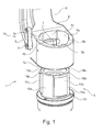
- Fig. 1 shows a Nietbügelkopplung 1 with a Nietbügel 2 and a hydraulic drive (not shown here) arranged Nietbügelanalysis 3.
- the Nietbügel 2 has three female threaded sections 4a, 4b, 4c and three internal thread-free sections 5a, 5b, 5c.
- the internal thread sections 4a, 4b, 4c and the internal thread-free sections 5a, 5b, 5c are arranged coaxially and at a uniform distance from each other about a threaded longitudinal axis 6 (shown here as a dashed line) and each have the same size. Ie. the distance of the arcuate portions respectively enclosed by the thread sections 4a, 4b, 4c and the path comprised by the thread-free sections 5a, 5b, 5c is always the same length.
- a thread-free section 5a, 5b, 5c and a threaded section 4a, 4b, 4c together comprise an angle of 120 ° about the threaded axis 6.
- the unthreaded section 5a, 5b, 5c comprises an angle of approximately 62 °, the threaded section at an angle of about 58 °.
- the difference between a thread-free portion 5a, 5b, 5c and a threaded portion 4a, 4b, 4c is thus approximately 4 °.
- a difference in the range between 0.5 ° to 20 ° (or larger) may be formed, wherein the thread-free portion always an equal, preferably a slightly larger angle than the threaded portion. That is, the distance of the circular arc comprised by the unthreaded portion is always equal to or at least slightly longer than the distance of the circular arc encompassed by the threaded portion (inner and / or outer threads).
- a rotatably mounted locking bolt 7 is arranged on the rivet bracket 2.
- the locking bolt 7 cuts a threaded portion 4a of the rivet bracket 2 in a central position and stands with a first end 7a out of the rivet bracket 2 out.
- the locking bolt 7 is circular in cross-section, wherein the protruding from the rivet bracket 2 end 7a of the locking bolt 7 is oval shaped.
- the protruding end 7 a of the locking bolt 7 is connected to a control lever 8.
- the locking bolt 7 is rotatably mounted about its longitudinal axis 9 in the rivet 2.
- the longitudinal axis 9 is transversely, here aligned at an angle of 90 ° to the threaded longitudinal axis 6, arranged.
- the locking bolt 7 has two flat recesses 10a, 10b.
- the flat recesses 10a, 10b are arranged along the longitudinal axis 9 in the region of the threaded portion 4a.
- Fig. 1 the locking bolt 7 is shown in a release position. It can via a tilting movement of the control lever 8 from the release position into a locking position (see FIG. 2 ) to be turned around.
- a ball lock 10 is arranged on the adjusting lever 8 and engages in the locking position with a ball seat 11 arranged on the rivet hoop 2.
- a contact surface 12 for supporting on a rivet bracket 3 arranged support surface 13 is formed on the rivet bracket.
- externally threaded portions 14a, 14b, 14c and externally threaded portions 15a, 15b, 15c are disposed on the rivet bracket receptacle.
- the externally threaded portions 14a, 14b, 14c and the externally unthreaded portions 15a, 15b, 15c are also arranged coaxially and uniformly about the threaded longitudinal axis 6.
- the length of the externally threaded portions 14a, 14b, 14c and the externally unthreaded portions 15a, 15b is also identical and corresponds to the length of the female threaded portions 4a, 4b, 4c and female screw-free portions 5a, 5b, 5c.
- the internally threaded portions 4a, 4b, 4c are identical copies of each other.
- the respective thread starting points 18b, 18c are arranged in a plane perpendicular to the threaded longitudinal axis 6 (not shown here) as well as their respective threaded end points in a further plane perpendicular to the threaded longitudinal axis 6 .
- the external thread sections 14a, 14b, 14c are also identical copies of each other, whose respective starting points and end points each lie in a common plane perpendicular to the threaded longitudinal axis 6.
- the respective thread starting points are just like the respective threaded end points (inner and outer threads) in their respective plane at an angle of 120 ° about the thread axis 6 offset from each other.
- Fig. 2 shows in a partial sectional view and schematically the rivet bracket 2 and the rivet holder 3 from Fig. 1 in the starting position.
- the rivet bracket 2 is attached to the rivet holder 3.
- the male threaded portions 14a, 14b, 14c are engaged with the unthreaded portions 5a, 5b, 5c female thread and the female threaded portions 4a, 4b, 4c are engaged with the unthreaded portions 15a, 15b, 15c of the male thread.
- the locking bolt 7 is in the release position. At the flat recesses 10a, 10b, two locking edges 16a, 16b are arranged on the locking bolt 7.
- the female threaded portions 4a, 4b, 4c are each arranged at 60 ° to the respective male threaded portions 14a, 14b, 14c.
- the contact surface 12 and the support surface 13 are contactless.
- Fig. 3 shows the rivet bracket 2 and the rivet holder 3 from FIG. 1 in the use position, that is, the female threaded portions 4a, 4b, 4c are engaged with the male threaded portions 14a, 14b, 14c.
- the contact surface 12 and the support surface 13 are in contact.
- the locking bolt 7 is in the locking position, so that the locking edges 16a, 16b prevents unscrewing of the male threaded portion 14c engaged with the female threaded portion 4a.
Landscapes
- Engineering & Computer Science (AREA)
- Mechanical Engineering (AREA)
- General Engineering & Computer Science (AREA)
- Connection Of Plates (AREA)
- Insertion Pins And Rivets (AREA)
Applications Claiming Priority (1)
| Application Number | Priority Date | Filing Date | Title |
|---|---|---|---|
| DE102012103576.8A DE102012103576B4 (de) | 2012-04-24 | 2012-04-24 | Nietbügel, Nietbügelaufnahme sowie Nietbügelkopplung |
Publications (3)
| Publication Number | Publication Date |
|---|---|
| EP2656943A2 true EP2656943A2 (fr) | 2013-10-30 |
| EP2656943A3 EP2656943A3 (fr) | 2015-06-24 |
| EP2656943B1 EP2656943B1 (fr) | 2018-01-10 |
Family
ID=47998203
Family Applications (1)
| Application Number | Title | Priority Date | Filing Date |
|---|---|---|---|
| EP13160124.7A Active EP2656943B1 (fr) | 2012-04-24 | 2013-03-20 | Ensembe formé d'un étrier de machine de rivetage, son support, et leur accouplement |
Country Status (2)
| Country | Link |
|---|---|
| EP (1) | EP2656943B1 (fr) |
| DE (1) | DE102012103576B4 (fr) |
Cited By (1)
| Publication number | Priority date | Publication date | Assignee | Title |
|---|---|---|---|---|
| EP3599041A1 (fr) * | 2018-07-25 | 2020-01-29 | Airbus Operations (S.A.S.) | Outil portatif avec une tete demontable |
Family Cites Families (4)
| Publication number | Priority date | Publication date | Assignee | Title |
|---|---|---|---|---|
| ATE46639T1 (de) * | 1983-05-27 | 1989-10-15 | Nietek Pty Ltd | Zufuehrvorrichtungen fuer befestigungselemente mit kopf. |
| DE4310953A1 (de) * | 1993-04-02 | 1994-10-13 | Wolfgang Dipl Ing Luckhardt | Einpresseinrichtung zum Einpressen von Fügeteilen |
| US6811364B2 (en) * | 2002-09-23 | 2004-11-02 | Ken Kelzer | Quick connecting threaded coupler |
| US8307690B2 (en) * | 2009-08-28 | 2012-11-13 | Sps Technologies, Llc | Hand-tool system for installing blind fasteners |
-
2012
- 2012-04-24 DE DE102012103576.8A patent/DE102012103576B4/de active Active
-
2013
- 2013-03-20 EP EP13160124.7A patent/EP2656943B1/fr active Active
Non-Patent Citations (1)
| Title |
|---|
| None |
Cited By (3)
| Publication number | Priority date | Publication date | Assignee | Title |
|---|---|---|---|---|
| EP3599041A1 (fr) * | 2018-07-25 | 2020-01-29 | Airbus Operations (S.A.S.) | Outil portatif avec une tete demontable |
| FR3084269A1 (fr) * | 2018-07-25 | 2020-01-31 | Airbus Operations | Outil portatif avec une tete demontable |
| US11407024B2 (en) | 2018-07-25 | 2022-08-09 | Airbus Operations Sas | Portable tool having a removable head |
Also Published As
| Publication number | Publication date |
|---|---|
| DE102012103576A1 (de) | 2013-10-24 |
| EP2656943B1 (fr) | 2018-01-10 |
| DE102012103576B4 (de) | 2014-05-08 |
| EP2656943A3 (fr) | 2015-06-24 |
Similar Documents
| Publication | Publication Date | Title |
|---|---|---|
| EP3215099B1 (fr) | Griffe de serrage à poser sur une glissière pour table d'opération | |
| DE102015101829B4 (de) | Spannklaue zur Anbringung an einer Gleitschiene eines Operationstisches | |
| WO2017080634A1 (fr) | Ensemble de liaison pour rails de montage | |
| DE102015122385A1 (de) | Nockenbolzen und werkzeug-kupplungssystem für solche | |
| DE102013000624A1 (de) | Mutter zum Befestigen von Komponenten an einem profilierten Element über Schraubmittel und Verfahren zu deren Montage | |
| DE102004019237A1 (de) | Gewindeverbindung, insbesondere zur Befestigung eines Werkzeugs oder eines Werkzeugadapters, an einer Verlängerungseinrichtung | |
| DE102019111237B4 (de) | Zweiteilige Schraubenmutter mit hoher Andrückkraft | |
| EP1382509B1 (fr) | Colonne de direction | |
| EP2656943B1 (fr) | Ensembe formé d'un étrier de machine de rivetage, son support, et leur accouplement | |
| DE3520789C2 (fr) | ||
| EP2132848B1 (fr) | Dispositif d'ancrage d'un coffret d'installation dans une ouverture ménagée dans une paroi murale | |
| EP3120072B1 (fr) | Système de fixation de mât | |
| EP2578891B1 (fr) | Adapteur | |
| DE102014100272B4 (de) | Gehäuseanordnung | |
| EP1896219B1 (fr) | Point de raccordement | |
| EP2653065A2 (fr) | Raccordement de tuyau | |
| EP2017484B1 (fr) | Dispositif d'attache | |
| EP2514892A2 (fr) | Système de fixation d'une partie de ferrure | |
| EP3106263B1 (fr) | Tête de presse et outil de presse avec têtes de presse | |
| DE29506828U1 (de) | Vorrichtung zum Festlegen einer Ladung auf einem Fahrzeug | |
| WO2005087623A1 (fr) | Dispositif permettant de relier des dispositifs de transport | |
| WO2004013670A1 (fr) | Adaptateur servant a etablir une connexion optique par fiche | |
| EP3741261A1 (fr) | Meuble ainsi que ferrure pour un meuble | |
| DE2414532A1 (de) | Schnelltrenn-spannvorrichtung | |
| DE102015111868A1 (de) | Manuelles Tooling-Schnellkupplungssystem sowie Tooling, insbesondere Transfertooling, mit demselben |
Legal Events
| Date | Code | Title | Description |
|---|---|---|---|
| PUAI | Public reference made under article 153(3) epc to a published international application that has entered the european phase |
Free format text: ORIGINAL CODE: 0009012 |
|
| AK | Designated contracting states |
Kind code of ref document: A2 Designated state(s): AL AT BE BG CH CY CZ DE DK EE ES FI FR GB GR HR HU IE IS IT LI LT LU LV MC MK MT NL NO PL PT RO RS SE SI SK SM TR |
|
| AX | Request for extension of the european patent |
Extension state: BA ME |
|
| PUAL | Search report despatched |
Free format text: ORIGINAL CODE: 0009013 |
|
| AK | Designated contracting states |
Kind code of ref document: A3 Designated state(s): AL AT BE BG CH CY CZ DE DK EE ES FI FR GB GR HR HU IE IS IT LI LT LU LV MC MK MT NL NO PL PT RO RS SE SI SK SM TR |
|
| AX | Request for extension of the european patent |
Extension state: BA ME |
|
| RIC1 | Information provided on ipc code assigned before grant |
Ipc: B21J 15/10 20060101AFI20150521BHEP Ipc: F16M 11/04 20060101ALI20150521BHEP Ipc: B21J 15/30 20060101ALI20150521BHEP |
|
| 17P | Request for examination filed |
Effective date: 20151218 |
|
| RBV | Designated contracting states (corrected) |
Designated state(s): AL AT BE BG CH CY CZ DE DK EE ES FI FR GB GR HR HU IE IS IT LI LT LU LV MC MK MT NL NO PL PT RO RS SE SI SK SM TR |
|
| GRAP | Despatch of communication of intention to grant a patent |
Free format text: ORIGINAL CODE: EPIDOSNIGR1 |
|
| INTG | Intention to grant announced |
Effective date: 20170727 |
|
| GRAS | Grant fee paid |
Free format text: ORIGINAL CODE: EPIDOSNIGR3 |
|
| GRAA | (expected) grant |
Free format text: ORIGINAL CODE: 0009210 |
|
| AK | Designated contracting states |
Kind code of ref document: B1 Designated state(s): AL AT BE BG CH CY CZ DE DK EE ES FI FR GB GR HR HU IE IS IT LI LT LU LV MC MK MT NL NO PL PT RO RS SE SI SK SM TR |
|
| REG | Reference to a national code |
Ref country code: CH Ref legal event code: EP Ref country code: AT Ref legal event code: REF Ref document number: 961839 Country of ref document: AT Kind code of ref document: T Effective date: 20180115 |
|
| REG | Reference to a national code |
Ref country code: IE Ref legal event code: FG4D Free format text: LANGUAGE OF EP DOCUMENT: GERMAN |
|
| REG | Reference to a national code |
Ref country code: DE Ref legal event code: R096 Ref document number: 502013009212 Country of ref document: DE |
|
| REG | Reference to a national code |
Ref country code: FR Ref legal event code: PLFP Year of fee payment: 6 |
|
| REG | Reference to a national code |
Ref country code: NL Ref legal event code: MP Effective date: 20180110 |
|
| PG25 | Lapsed in a contracting state [announced via postgrant information from national office to epo] |
Ref country code: NL Free format text: LAPSE BECAUSE OF FAILURE TO SUBMIT A TRANSLATION OF THE DESCRIPTION OR TO PAY THE FEE WITHIN THE PRESCRIBED TIME-LIMIT Effective date: 20180110 |
|
| PG25 | Lapsed in a contracting state [announced via postgrant information from national office to epo] |
Ref country code: NO Free format text: LAPSE BECAUSE OF FAILURE TO SUBMIT A TRANSLATION OF THE DESCRIPTION OR TO PAY THE FEE WITHIN THE PRESCRIBED TIME-LIMIT Effective date: 20180410 Ref country code: FI Free format text: LAPSE BECAUSE OF FAILURE TO SUBMIT A TRANSLATION OF THE DESCRIPTION OR TO PAY THE FEE WITHIN THE PRESCRIBED TIME-LIMIT Effective date: 20180110 Ref country code: CY Free format text: LAPSE BECAUSE OF FAILURE TO SUBMIT A TRANSLATION OF THE DESCRIPTION OR TO PAY THE FEE WITHIN THE PRESCRIBED TIME-LIMIT Effective date: 20180110 Ref country code: ES Free format text: LAPSE BECAUSE OF FAILURE TO SUBMIT A TRANSLATION OF THE DESCRIPTION OR TO PAY THE FEE WITHIN THE PRESCRIBED TIME-LIMIT Effective date: 20180110 Ref country code: LT Free format text: LAPSE BECAUSE OF FAILURE TO SUBMIT A TRANSLATION OF THE DESCRIPTION OR TO PAY THE FEE WITHIN THE PRESCRIBED TIME-LIMIT Effective date: 20180110 Ref country code: HR Free format text: LAPSE BECAUSE OF FAILURE TO SUBMIT A TRANSLATION OF THE DESCRIPTION OR TO PAY THE FEE WITHIN THE PRESCRIBED TIME-LIMIT Effective date: 20180110 |
|
| PG25 | Lapsed in a contracting state [announced via postgrant information from national office to epo] |
Ref country code: RS Free format text: LAPSE BECAUSE OF FAILURE TO SUBMIT A TRANSLATION OF THE DESCRIPTION OR TO PAY THE FEE WITHIN THE PRESCRIBED TIME-LIMIT Effective date: 20180110 Ref country code: BG Free format text: LAPSE BECAUSE OF FAILURE TO SUBMIT A TRANSLATION OF THE DESCRIPTION OR TO PAY THE FEE WITHIN THE PRESCRIBED TIME-LIMIT Effective date: 20180410 Ref country code: SE Free format text: LAPSE BECAUSE OF FAILURE TO SUBMIT A TRANSLATION OF THE DESCRIPTION OR TO PAY THE FEE WITHIN THE PRESCRIBED TIME-LIMIT Effective date: 20180110 Ref country code: IS Free format text: LAPSE BECAUSE OF FAILURE TO SUBMIT A TRANSLATION OF THE DESCRIPTION OR TO PAY THE FEE WITHIN THE PRESCRIBED TIME-LIMIT Effective date: 20180510 Ref country code: LV Free format text: LAPSE BECAUSE OF FAILURE TO SUBMIT A TRANSLATION OF THE DESCRIPTION OR TO PAY THE FEE WITHIN THE PRESCRIBED TIME-LIMIT Effective date: 20180110 Ref country code: PL Free format text: LAPSE BECAUSE OF FAILURE TO SUBMIT A TRANSLATION OF THE DESCRIPTION OR TO PAY THE FEE WITHIN THE PRESCRIBED TIME-LIMIT Effective date: 20180110 Ref country code: GR Free format text: LAPSE BECAUSE OF FAILURE TO SUBMIT A TRANSLATION OF THE DESCRIPTION OR TO PAY THE FEE WITHIN THE PRESCRIBED TIME-LIMIT Effective date: 20180411 |
|
| PG25 | Lapsed in a contracting state [announced via postgrant information from national office to epo] |
Ref country code: MT Free format text: LAPSE BECAUSE OF FAILURE TO SUBMIT A TRANSLATION OF THE DESCRIPTION OR TO PAY THE FEE WITHIN THE PRESCRIBED TIME-LIMIT Effective date: 20180110 |
|
| REG | Reference to a national code |
Ref country code: DE Ref legal event code: R097 Ref document number: 502013009212 Country of ref document: DE |
|
| PG25 | Lapsed in a contracting state [announced via postgrant information from national office to epo] |
Ref country code: EE Free format text: LAPSE BECAUSE OF FAILURE TO SUBMIT A TRANSLATION OF THE DESCRIPTION OR TO PAY THE FEE WITHIN THE PRESCRIBED TIME-LIMIT Effective date: 20180110 Ref country code: RO Free format text: LAPSE BECAUSE OF FAILURE TO SUBMIT A TRANSLATION OF THE DESCRIPTION OR TO PAY THE FEE WITHIN THE PRESCRIBED TIME-LIMIT Effective date: 20180110 Ref country code: AL Free format text: LAPSE BECAUSE OF FAILURE TO SUBMIT A TRANSLATION OF THE DESCRIPTION OR TO PAY THE FEE WITHIN THE PRESCRIBED TIME-LIMIT Effective date: 20180110 |
|
| REG | Reference to a national code |
Ref country code: CH Ref legal event code: PL |
|
| PLBE | No opposition filed within time limit |
Free format text: ORIGINAL CODE: 0009261 |
|
| STAA | Information on the status of an ep patent application or granted ep patent |
Free format text: STATUS: NO OPPOSITION FILED WITHIN TIME LIMIT |
|
| PG25 | Lapsed in a contracting state [announced via postgrant information from national office to epo] |
Ref country code: CZ Free format text: LAPSE BECAUSE OF FAILURE TO SUBMIT A TRANSLATION OF THE DESCRIPTION OR TO PAY THE FEE WITHIN THE PRESCRIBED TIME-LIMIT Effective date: 20180110 Ref country code: MC Free format text: LAPSE BECAUSE OF FAILURE TO SUBMIT A TRANSLATION OF THE DESCRIPTION OR TO PAY THE FEE WITHIN THE PRESCRIBED TIME-LIMIT Effective date: 20180110 Ref country code: SK Free format text: LAPSE BECAUSE OF FAILURE TO SUBMIT A TRANSLATION OF THE DESCRIPTION OR TO PAY THE FEE WITHIN THE PRESCRIBED TIME-LIMIT Effective date: 20180110 Ref country code: DK Free format text: LAPSE BECAUSE OF FAILURE TO SUBMIT A TRANSLATION OF THE DESCRIPTION OR TO PAY THE FEE WITHIN THE PRESCRIBED TIME-LIMIT Effective date: 20180110 Ref country code: SM Free format text: LAPSE BECAUSE OF FAILURE TO SUBMIT A TRANSLATION OF THE DESCRIPTION OR TO PAY THE FEE WITHIN THE PRESCRIBED TIME-LIMIT Effective date: 20180110 |
|
| REG | Reference to a national code |
Ref country code: BE Ref legal event code: MM Effective date: 20180331 |
|
| 26N | No opposition filed |
Effective date: 20181011 |
|
| REG | Reference to a national code |
Ref country code: IE Ref legal event code: MM4A |
|
| PG25 | Lapsed in a contracting state [announced via postgrant information from national office to epo] |
Ref country code: LU Free format text: LAPSE BECAUSE OF NON-PAYMENT OF DUE FEES Effective date: 20180320 |
|
| PG25 | Lapsed in a contracting state [announced via postgrant information from national office to epo] |
Ref country code: IE Free format text: LAPSE BECAUSE OF NON-PAYMENT OF DUE FEES Effective date: 20180320 |
|
| PG25 | Lapsed in a contracting state [announced via postgrant information from national office to epo] |
Ref country code: BE Free format text: LAPSE BECAUSE OF NON-PAYMENT OF DUE FEES Effective date: 20180331 Ref country code: CH Free format text: LAPSE BECAUSE OF NON-PAYMENT OF DUE FEES Effective date: 20180331 Ref country code: SI Free format text: LAPSE BECAUSE OF FAILURE TO SUBMIT A TRANSLATION OF THE DESCRIPTION OR TO PAY THE FEE WITHIN THE PRESCRIBED TIME-LIMIT Effective date: 20180110 Ref country code: LI Free format text: LAPSE BECAUSE OF NON-PAYMENT OF DUE FEES Effective date: 20180331 |
|
| REG | Reference to a national code |
Ref country code: AT Ref legal event code: MM01 Ref document number: 961839 Country of ref document: AT Kind code of ref document: T Effective date: 20180320 |
|
| PG25 | Lapsed in a contracting state [announced via postgrant information from national office to epo] |
Ref country code: AT Free format text: LAPSE BECAUSE OF NON-PAYMENT OF DUE FEES Effective date: 20180320 |
|
| PG25 | Lapsed in a contracting state [announced via postgrant information from national office to epo] |
Ref country code: TR Free format text: LAPSE BECAUSE OF FAILURE TO SUBMIT A TRANSLATION OF THE DESCRIPTION OR TO PAY THE FEE WITHIN THE PRESCRIBED TIME-LIMIT Effective date: 20180110 |
|
| PG25 | Lapsed in a contracting state [announced via postgrant information from national office to epo] |
Ref country code: HU Free format text: LAPSE BECAUSE OF FAILURE TO SUBMIT A TRANSLATION OF THE DESCRIPTION OR TO PAY THE FEE WITHIN THE PRESCRIBED TIME-LIMIT; INVALID AB INITIO Effective date: 20130320 Ref country code: PT Free format text: LAPSE BECAUSE OF FAILURE TO SUBMIT A TRANSLATION OF THE DESCRIPTION OR TO PAY THE FEE WITHIN THE PRESCRIBED TIME-LIMIT Effective date: 20180110 |
|
| PG25 | Lapsed in a contracting state [announced via postgrant information from national office to epo] |
Ref country code: MK Free format text: LAPSE BECAUSE OF NON-PAYMENT OF DUE FEES Effective date: 20180110 |
|
| PGFP | Annual fee paid to national office [announced via postgrant information from national office to epo] |
Ref country code: IT Payment date: 20250331 Year of fee payment: 13 |
|
| PGFP | Annual fee paid to national office [announced via postgrant information from national office to epo] |
Ref country code: GB Payment date: 20260317 Year of fee payment: 14 |
|
| PGFP | Annual fee paid to national office [announced via postgrant information from national office to epo] |
Ref country code: DE Payment date: 20260325 Year of fee payment: 14 |
|
| PGFP | Annual fee paid to national office [announced via postgrant information from national office to epo] |
Ref country code: FR Payment date: 20260324 Year of fee payment: 14 |